EP3499041A1 - Schraubenvakuumpumpe - Google Patents
Schraubenvakuumpumpe Download PDFInfo
- Publication number
- EP3499041A1 EP3499041A1 EP17207558.2A EP17207558A EP3499041A1 EP 3499041 A1 EP3499041 A1 EP 3499041A1 EP 17207558 A EP17207558 A EP 17207558A EP 3499041 A1 EP3499041 A1 EP 3499041A1
- Authority
- EP
- European Patent Office
- Prior art keywords
- screw
- vacuum pump
- section
- rotors
- housing
- Prior art date
- Legal status (The legal status is an assumption and is not a legal conclusion. Google has not performed a legal analysis and makes no representation as to the accuracy of the status listed.)
- Granted
Links
Images





Classifications
-
- F—MECHANICAL ENGINEERING; LIGHTING; HEATING; WEAPONS; BLASTING
- F04—POSITIVE - DISPLACEMENT MACHINES FOR LIQUIDS; PUMPS FOR LIQUIDS OR ELASTIC FLUIDS
- F04C—ROTARY-PISTON, OR OSCILLATING-PISTON, POSITIVE-DISPLACEMENT MACHINES FOR LIQUIDS; ROTARY-PISTON, OR OSCILLATING-PISTON, POSITIVE-DISPLACEMENT PUMPS
- F04C18/00—Rotary-piston pumps specially adapted for elastic fluids
- F04C18/08—Rotary-piston pumps specially adapted for elastic fluids of intermeshing-engagement type, i.e. with engagement of co-operating members similar to that of toothed gearing
- F04C18/12—Rotary-piston pumps specially adapted for elastic fluids of intermeshing-engagement type, i.e. with engagement of co-operating members similar to that of toothed gearing of other than internal-axis type
- F04C18/14—Rotary-piston pumps specially adapted for elastic fluids of intermeshing-engagement type, i.e. with engagement of co-operating members similar to that of toothed gearing of other than internal-axis type with toothed rotary pistons
- F04C18/16—Rotary-piston pumps specially adapted for elastic fluids of intermeshing-engagement type, i.e. with engagement of co-operating members similar to that of toothed gearing of other than internal-axis type with toothed rotary pistons with helical teeth, e.g. chevron-shaped, screw type
-
- F—MECHANICAL ENGINEERING; LIGHTING; HEATING; WEAPONS; BLASTING
- F04—POSITIVE - DISPLACEMENT MACHINES FOR LIQUIDS; PUMPS FOR LIQUIDS OR ELASTIC FLUIDS
- F04C—ROTARY-PISTON, OR OSCILLATING-PISTON, POSITIVE-DISPLACEMENT MACHINES FOR LIQUIDS; ROTARY-PISTON, OR OSCILLATING-PISTON, POSITIVE-DISPLACEMENT PUMPS
- F04C18/00—Rotary-piston pumps specially adapted for elastic fluids
- F04C18/08—Rotary-piston pumps specially adapted for elastic fluids of intermeshing-engagement type, i.e. with engagement of co-operating members similar to that of toothed gearing
- F04C18/082—Details specially related to intermeshing engagement type pumps
- F04C18/084—Toothed wheels
-
- F—MECHANICAL ENGINEERING; LIGHTING; HEATING; WEAPONS; BLASTING
- F04—POSITIVE - DISPLACEMENT MACHINES FOR LIQUIDS; PUMPS FOR LIQUIDS OR ELASTIC FLUIDS
- F04C—ROTARY-PISTON, OR OSCILLATING-PISTON, POSITIVE-DISPLACEMENT MACHINES FOR LIQUIDS; ROTARY-PISTON, OR OSCILLATING-PISTON, POSITIVE-DISPLACEMENT PUMPS
- F04C25/00—Adaptations of pumps for special use of pumps for elastic fluids
- F04C25/02—Adaptations of pumps for special use of pumps for elastic fluids for producing high vacuum
Definitions
- the present invention relates to a screw vacuum pump having a housing, two screw rotors arranged in the housing and engaged with each other, which repeatedly conveyed flow volumes of the process gas to convey a process gas in cooperation with the housing and convey toward an outlet.
- Screw vacuum pumps generally comprise complex pump-active geometries, in particular screw profiles of screw rotors and a corresponding housing for the screw rotors.
- An interaction of these geometries requires a high degree of precision in their production. It can therefore be very complicated and expensive to manufacture or control the geometries.
- a screw vacuum pump with the features of claim 1, and in particular by the fact that the screw rotors each have at least two adjacent sections along the screw axis, wherein the screw rotors in each case in a closer to an inlet first section at least substantially constant and in a second portion having a lower slope than in the first portion, and wherein with respect to the screw axis, the first portion is longer than a closed delivery volume in the first section.
- a respective screw profile cooperates with the housing to enclose a delivery volume.
- the delivery volume to be closed reaches the second portion before its completion with respect to the inlet, this will result in some of the process gas being expelled back to the inlet.
- a high manufacturing precision of the housing in the inlet area was previously necessary in order to ensure a precisely defined completion of the delivery volume.
- a precise manufacture of the inlet area is complicated and is made more difficult, for example, by the fact that a casting mold for the housing wears over several casting cycles.
- the first section is longer than a closed delivery volume according to the invention, it is ensured that the second section is not reached before the delivery volume has been completed.
- the manufacturing precision of the housing in the inlet area can thus be reduced without the risk of the process gas being pushed back towards the inlet.
- the reduced requirement for manufacturing precision greatly simplifies the manufacture of the vacuum pump. This allows a more stable manufacturing process with fewer defective components. This is particularly advantageous because the housing in the inlet area is often difficult to measure, especially only consuming by a 3D coordinate measuring system. Without a measurement deviations may be detected only in a final test of the screw vacuum pump, which leads to high costs for re-assembly in case of failure.
- the invention reduces the influence of manufacturing precision so that deviations from a desired shape are less relevant or harmless.
- the invention not only simplifies the production of the housing, but also the production of the screw rotors, since in the invention relatively long first section with relatively large pitch larger tools and / or tools can be used with higher chip volume for profile production. This reduces the processing time and the associated manufacturing costs.
- the processing time can be further reduced, for example be that a respective screw contour of the screw rotors, especially only or in the first section, already during casting at least in a precontour for further machining is formed.
- the screw vacuum pump according to the invention even has an improved suction capacity at relatively high suction pressures. This is attributed to the fact that with the longer first section, the gaps in the first section which form between the rotors with one another and, in particular, with respect to the housing, are longer. The process gas in the area of internal compression, which results in particularly high internal pressures at high intake pressures, must thus overcome longer gaps for the return flow. The return flow is consequently made more difficult or better sealed.
- the screw vacuum pump according to the invention is therefore not only particularly simple to produce with justifiable design restrictions, but even exhibits improved vacuum performance in certain pressure ranges.
- a closed delivery volume can generally be understood - except for unavoidable gaps between the rotors and with respect to the housing - completed area extending between two screw passes of a respective rotor along the screw profile around the rotor and outwardly from the housing and along the screw profile of each other rotor is limited.
- the delivery volume moves during the pumping process along the respective screw rotor in the profile from the inlet to Outlet, whereby the pumping action is provided.
- the delivery volume can become smaller on the way between inlet and outlet. This is called internal compression.
- the completed delivery volume can cover an angle of 360 ° about the screw axis of the respective rotor.
- the first portion corresponds to at least 1.25 times, in particular at least 1.5 times, in particular at least 1.75 times, in particular at least twice the length of the delivery volume.
- a closing surface for the screw rotors can be formed, which is adapted in terms of their shape to the screw rotors such that a respective delivery volume for sucking opened and can be completed for conveying.
- the end surface extends in particular at least substantially perpendicular to the screw axes.
- the termination surface forms e.g. a, in particular inner, end face of the housing.
- the end surface may preferably be formed as a free-form surface and / or extend at least substantially parallel to at least one corresponding screw profile.
- two parallel to the screw profiles portions of the end surface may be provided, which are in particular to a raised in relation to the screw axis, in particular lower, range and / or reduced, in particular upper region, merged.
- the end surface can be formed in general, for example, in the housing.
- the housing may be formed, for example, as a casting.
- the end surface is in a casting, in particular the housing, trained and unedited. As a result, the manufacturing step of a machining of the end surface is completely saved, which further simplifies the production of the housing.
- a helical profile of a respective helical rotor is formed by a cycloid.
- Such a screw profile can be advantageous shape demand.
- a screw profile of a respective screw rotor is designed to be double-threaded.
- a particularly small imbalance of the corresponding screw rotor is achieved.
- compensation elements e.g. Compensating masses that require additional space, and / or compensation holes, in which material can deposit, be waived.
- higher speeds can be made possible.
- the screw rotors each have an at least substantially constant pitch in the second section.
- Such screw rotors are particularly easy to design and manufacture, since the constant pitch forms a relatively simple geometry.
- the screw rotors each have at least one third section and their pitch in the third section is smaller than in the second section. As a result, an additional internal compression can be realized.
- the slope in the third section may in particular be at least substantially constant.
- the screw rotors each have over their entire pump-active length a plurality of sections of different pitch, the slope in all sections, in particular at least range or subsectional, in particular, in each case, is constant. Both contribute to a simplified design or production.
- the pitch of the screw profile changes along a screw axis basically only in transition areas between the sections.
- a transition region is in particular smaller than a section, in particular as the adjacent sections.
- all transition areas are smaller than all sections.
- the screw vacuum pump may have, for example, an internal compression with a compression ratio of less than 5 to 1, in particular less than 4 to 1, in particular less than 3.5 to 1, and / or greater than 2 to 1, in particular greater than 3 to 1.
- a respective screw profile may e.g. more than 7, in particular more than 10, in particular more than 12, in particular 13 completed delivery volumes simultaneously form or promote.
- a respective screw rotor can in particular have a ratio of the length of its screw profile to its diameter of at least 2.0, in particular at least 2.5, in particular at least 3.0 and / or at most 5.0, in particular 4.0.
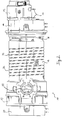
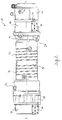
- a screw vacuum pump 10 which has a motor 12, a gear box 14, a housing 16, a bearing plate 18 and a cover 20.
- the screw vacuum pump 10 delivers a process gas from an inlet 22 to a downward, in Fig. 3 visible outlet 24.
- an active liquid cooling is provided which emerges from a housing of the engine 12.
- an active liquid cooling which has two cooling lines, which in Fig. 1 not shown, but their course through corresponding grooves 32 of the housing 16 is indicated, in which the cooling lines are pressed.
- active liquid coolers are provided in the gear box 14 and in the lid 20 and are each formed here as immersion coolers 34, which are described below with reference to FIG Fig. 5 be explained in more detail.
- the housing 16 of the screw vacuum pump 10 has a sidecut 36.
- the sidecut 36 is arranged in the region of the outlet 24.
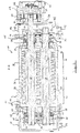
- Fig. 4 the screw vacuum pump 10 is shown in a sectional view, the sectional plane of the line AA in Fig. 3 equivalent.
- the screw profiles 38 and 40 in cooperation with the housing 16, form a pump-active area of the screw vacuum pump 10 and repeatedly deliver closed volumes of delivery of the process gas from the inlet 22 to the outlet 24, in FIG Fig. 4 from left to right.
- the pumping power of the screw vacuum pump 10 depends on the size and shape of different gaps in the pump active region, which are unavoidable due to the relative movement of rotors 28, 30 and housing 16, but are small and as constant as possible for the purpose of good pumping performance. Temperature changes in the components involved lead to their change in shape. The measures described herein for the prevention, removal and general control of heat in the pump 10 thus cause the least possible change in shape and, as a result, controllable gaps as far as possible. The gaps can therefore be designed more precisely, which improves the pumping power and its efficiency.
- the screw rotor 28 is directly, so without intermediate clutch, driven by the motor 12.
- the screw rotor 30, in contrast, is driven via a synchronization gear 42 with toothed wheels 43 in a defined angular relationship with the screw rotor 28.
- the motor 12 comprises a housing 44, which is made of aluminum, for example, and in which cooling lines 26 for the active liquid cooling are formed.
- the motor 12 further includes a wound stator 46 which, together with a magnet carrier 48 mounted on a shaft end of the screw rotor 28, forms an electric motor and a direct drive for the screw rotor 28.
- the screw rotor 28 forms a rotor of the motor 12.
- the magnet carrier 48 comprises a plurality of permanent magnets.
- the motor 12 thus forms a permanent magnet synchronous machine with internal magnets, which is also referred to as IPMSM.
- the stator 46 is arranged in a potting body 50 which isolates electrical conductors (not shown) at the stator 46 and leads them in isolation to a circuit board 52.
- the potting body 50 here, in conjunction with the circuit board 52, forms a vacuum-tight connection of the motor 12 to an electronic control system provided in a region of atmospheric pressure. It can e.g. an external frequency converter for the motor 12 may be provided. Alternatively or additionally, at least part of control electronics for the motor 12 may be provided on the circuit board 52.
- the synchronization gear 42 is arranged in the gear box 14.
- oil is provided as a lubricant, which is distributed by splash disks 54 via the synchronization gear 42 and adjacent bearings 56.
- the waist 36 forms a shield or thermal barrier, in particular for heat produced in the area of the screw rotors 28, 30 during the pumping operation. Characterized in that a small material cross-section remains, and in that a heat path is extended by the change in shape, the heat from the screw rotor, which otherwise spreads in the housing 16, prevented from entering into otherworldly areas.
- the oil in the gear box 14 and the bearings 56 are protected from excessive temperatures.
- the immersion cooler 34 arranged in the gearbox 14 also contributes to the temperature reduction. This is arranged in an oil bath of the gear box 14, not shown, and thus cools the oil directly.
- a respective deflector 58 forms a barrier for the oil in the gearbox so that it does not enter a pump-active region or a vacuum region, in particular an outlet region.
- the deflector 58 includes an unspecified Abschleuderkante for the oil. Opposite the Abschleuderkante a drain groove is formed in the housing 16, which absorbs thrown off oil and this passes back into the gear box 14 and in a local oil bath. The oil, which is conveyed or distributed by the spray disks 54 on the gear 42 and bearing 56, is thus removed by the deflectors 58 again from the rotors 28 and 30 respectively.
- piston rings are provided on a piston ring carrier 60. These form a non-contact seal and thus avoid frictional heat.
- the Deflektoren 58 lead back as much oil to the gearbox 14, so that as little as possible oil is present at the piston rings. This achieves an overall reliable sealing effect with particularly low heat production.
- the screw rotors 28 and 30 have in their respective screw profile 38 and 40, three sections of different pitch.
- a in pumping direction first section 62 in Fig. 4 left, forms a suction section and has a constant and the largest slope under the three sections.
- the first portion 62 is longer than a closed delivery volume in the first portion with respect to a screw axis 63 extending along a respective rotor 28, 30, respectively.
- a second portion 64 has a plurality of subsections, which are not further referenced, with different but each constant pitches in the screw profile 38 and 40, wherein the slopes are lower than in the first section.
- the second section 64 forms the longest section here.
- a third section 66 of even lower pitch forms an ejection section. In the third section, again, there is a constant slope. Due to the reduced slope along the pumping direction, an internal compression is effected, which compresses the process gas even before the ejection.
- the rotors 28, 30 and the screw profiles 38, 40 can be particularly easy to design and manufacture by providing the constant sections. As it is based on Fig. 4 As can be seen, an extended first portion 62 leads to correspondingly elongated gaps between the screw profiles 28, 30 and the housing 16, so that the path or the gap from the inner compression at the transition of the sections 62 and 64 towards a suction chamber or suction area 67 longer is. Accordingly, the sealing effect of the gap is correspondingly increased, which leads to improved sealing of the internal compression relative to the intake region 67, especially at high differential pressures.
- the screw vacuum pump 10 thus has an internal compression.
- the size of a delivery volume is determined by a cross section of a screw profile 38, 40 and its slope.
- the size of a delivery volume on the inlet side or in the section 62 determines a theoretical pumping speed of the screw pump 10.
- the pitch of the screw profile 38, 40 is constant on the inlet side over section 62, so that the delivery volume is compressed only after completion by the internal compression. If a respective rotor 28, 30 closes a respective delivery volume too early or too late, or if the internal compression begins too early, the theoretical pumping speed of the pump decreases.
- the size of a respective delivery volume on the outlet side or in section 66 determines the power consumption of the pump in operation at an achievable final pressure.
- the ratio of the sizes of the delivery volume on the inlet side and outlet side or in the sections 62 and 66 corresponds to the ratio of the internal compression of the pump.
- the pitch over several revolutions of the screw profile 38, 40 is constant.
- the slope corresponds approximately to the minimum of achievable by a particular machining tool pitch and is thus, in particular with cost considerations, manufacturing technology.
- a plurality of revolutions that is, a plurality of completed delivery volumes, are provided in section 66, a return flow due to a pressure difference between the columns is compensated.
- the overall gradient along the rotors 28, 30 and the size of the gaps formed between the rotors 28, 30 and between rotors 28, 30 and the housing 16 determine the vacuum performance data of the pump, ie in particular the pumping speed and an achievable final pressure.
- the screw profiles 38, 40 have by their saussen morte configuration on a particularly low imbalance. Thus, for example, there are no compensating elements, such as e.g. Compensation masses that require additional space, and / or compensation holes, in which material can deposit, necessary.
- the pump can be operated with the two-speed cycloidal screw profiles 38, 40 in a wide speed range, in particular with speed control, and / or for example in a stand-by mode.
- the compression of the process gas in general generates heat, which is dissipated in the screw pump 10 primarily by a liquid cooling.
- a liquid cooling In Fig. 4 the grooves 32 provided for this purpose are visible. Cooling lines of the liquid cooling extend here and preferably in the longitudinal direction over a wide range of screw profiles, in particular over at least half the length of the screw profiles.
- the liquid cooling is arranged in the region or in the vicinity of an internal compression.
- bearing plate 18 At an inlet end of the housing 16 of the bearing plate 18 is attached. This carries, inter alia, a further storage with bearings 68, which form a loose storage.
- bearing plate 70 which is formed integrally with the housing 16 but may also be formed separately, the bearing plate 68 is formed as a separate component, but may also be integrally formed.
- spray disks 54, deflectors 58 and a piston ring carrier 60 with a plurality of piston rings are also provided, which operate in accordance with the outlet-side arrangement.
- a further, separately executed oil bath is provided in the lid 20.
- a dip cooler 34 is provided for this oil bath.
- a cooling line in a wall of the bearing plate 14 and / or the cover 20 may be provided, in particular encapsulated
- a biasing device in particular a spring, be provided, which is provided in particular at a floating bearing of the rotor and / or inlet side.
- the biasing device can for example also absorb forces acting on the rotors by means of helical gears and / or generally guarantee a design-appropriate preloading of the bearings, regardless of the operating state, with changing pressures or pressure ratios.
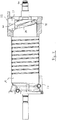
- a dip cooler 34 is shown as it is arranged in the gear box 14 and in the cover 20 of the screw vacuum pump 10.
- the immersion coolers 34 are thus formed identically, which leads to a small number of parts and low production costs.
- the immersion cooler 34 has a cooling line 72 which extends through a heat sink 74.
- the heat sink has a structuring to increase the surface of the heat sink in order to optimize the heat transfer.
- the immersion cooler 34 also has a flange 76 with which the immersion cooler 34 is attached.
- FIG. 6 the suction region 67 of the screw vacuum pump 10 is illustrated in a perspective sectional view.
- respective suction-side ends of the screw profiles 38 and 40 are arranged which, due to their rotation and in cooperation with a closing surface 78, repeatedly close up delivery volumes and convey along the rotor axes to the outlet 24.
- the end face 78 is substantially formed as a free-form surface, so it has a deviating from a simple plane, relatively complex shape.
- the end surface 78 has a roof-like, lower region 80 and a valley-like or channel-like upper region 82.
- a machining of the end surface 78 would therefore be very expensive, especially if high precision is required.
- the end surface 78 is executed unprocessed. It is formed in a casting of the housing 16 by a corresponding shape. While this provides a relatively inaccurate end surface 78, this is essentially unproblematic because of the inventively relatively long first portion 62. The machining can thus be advantageously saved here.
- FIG. 6 The sectional view of the Fig. 6 is in Fig. 7 shown in a side view to further illustrate the course of the end surface 78. Only the screw rotor 30 is visible, since it covers the screw rotor 28 in this view.
- the end surface 78 extends in a region surrounding the screw rotor 30 substantially parallel or corresponding to its screw profile 40.
- the distance between the screw profile 40 and the end surface 78 decreases until the distance is zero and a delivery volume in the corresponding profile gap 84 is completed.
- Fig. 8 the housing 16 of the screw vacuum pump 10 is shown in perspective view without the screw rotors 28, 30.
- the complex end surface 78 can be brought into a desired shape precisely only under great expense, in particular by means of cutting processes, such as trimming. Because of its complex shape, the end surface 78 can not be measured or can only be measured at great expense, and thus additionally harbors a danger for series production, since any defects may be uncovered without costly surveying possibly only during a final inspection of the pump. This is associated with high assembly or production costs and expensive rejects.
- the invention generally reduces the impact of the accuracy of the termination surface 78 on the vacuum performance data.
- Fig. 9 shows a diagram whose abscissa represents a pressure p in Hektopascal of a process gas at the inlet of a investigated lingvakuumpe and its ordinate a pumping speed S in cubic meters per hour of the pump. Two curves 86 and 88 of the pumping speed as a function of the inlet pressure are shown.
- the dashed line 86 is based on an exemplary screw vacuum pump with an inlet area or with a closing surface, which were machined to a desired contour.
- the length of a first section of constant pitch essentially corresponds to the length of a closed delivery volume in the first section.
- the exemplary screw vacuum pump of the course 86 is consequently not designed according to the invention.
- the solid curve 88 was recorded for a further exemplary screw vacuum in which an allowance provided for machining the end face was left and not machined. Otherwise, the screw vacuum pump of the run 88 is formed identically to the screw vacuum pump of the run 86. The two pumps or end surfaces thus differ only by a certain allowance. The allowance is provided in the direction of the rotor axes, which is why with unchanged rotors, a respective delivery volume is completed earlier and thus the first section is longer than a delivery volume.
- the screw vacuum pump of the course 88 is consequently designed according to the invention.
- Both courses 86 and 88 have a pumping speed pump with internal compression typical pumping speed.
- the pumping speed is greatest in a medium pressure range.
- the pumping speed is at high pressures or at the beginning of a pumpdown, in Fig. 9 right, lower.
- the absorbency decreases when a final pressure is reached Fig. 9 left, zero.
- An arrow 92 indicates that the achievable final pressure in the screw vacuum pump with allowance, ie during the course 88, is lower or better. This is attributed to the fact that the overall pump-active length of the screw rotors is greater due to the oversize. The gaps between the rotors and the housing are correspondingly longer, so that overall a better seal against return flows from the outlet to the inlet is achieved.
- the screw vacuum pump according to the invention in particular its housing, is particularly easy to produce, since the influence of the corresponding surface accuracy has been reduced.
- this makes it possible to dispense with a complex, machining of the housing in the inlet region or on a closure surface.
- a negative influence on the vacuum power is low and in some pressure ranges, the invention even leads to an improvement of the performance data.
Landscapes
- Engineering & Computer Science (AREA)
- Mechanical Engineering (AREA)
- General Engineering & Computer Science (AREA)
- Applications Or Details Of Rotary Compressors (AREA)
Abstract
Description
- Die vorliegende Erfindung betrifft eine Schraubenvakuumpumpe mit einem Gehäuse, zwei in dem Gehäuse angeordneten und miteinander in Eingriff stehenden Schraubenrotoren, die zum Fördern eines Prozessgases in Zusammenwirkung mit dem Gehäuse wiederholt abgeschlossene Fördervolumina des Prozessgases bilden und in Richtung eines Auslasses fördern.
- Schraubenvakuumpumpen umfassen generell komplexe pumpaktive Geometrien, insbesondere Schraubenprofile von Schraubenrotoren und ein korrespondierendes Gehäuse für die Schraubenrotoren. Ein Zusammenwirken dieser Geometrien erfordert eine hohe Präzision bei deren Fertigung. Es kann daher sehr aufwendig und teuer sein, die Geometrien herzustellen bzw. zu kontrollieren.
- Es ist eine Aufgabe der Erfindung, eine erforderliche Fertigungspräzision zumindest für einen Teilbereich einer pumpaktiven Geometrie zu verringern.
- Diese Aufgabe wird durch eine Schraubenvakuumpumpe mit den Merkmalen des Anspruchs 1 gelöst, und insbesondere dadurch, dass die Schraubenrotoren jeweils zumindest zwei entlang der Schraubenachse benachbarte Abschnitte aufweisen, wobei die Schraubenrotoren jeweils in einem näher an einem Einlass gelegenen ersten Abschnitt eine zumindest im Wesentlichen konstante und in einem zweiten Abschnitt eine niedrigere Steigung als im ersten Abschnitt aufweisen, und wobei in Bezug auf die Schraubenachse der erste Abschnitt länger ist als ein abgeschlossenes Fördervolumen im ersten Abschnitt.
- An einem Einlass der Schraubenvakuumpumpe wirkt ein jeweiliges Schraubenprofil mit dem Gehäuse zusammen, um ein Fördervolumen einzuschließen. Sofern das abzuschließende Fördervolumen vor seinem Abschluss gegenüber dem Einlass den zweiten Abschnitt erreicht, führt dies dazu, dass das Prozessgas teilweise zurück zum Einlass hin ausgestoßen wird. Deswegen war bisher eine hohe Fertigungspräzision des Gehäuses im Einlassbereich notwendig, um für einen präzise definierten Abschluss des Fördervolumens zu sorgen. Eine präzise Fertigung des Einlassbereichs ist aufwendig und wird z.B. dadurch erschwert, dass eine Gussform für das Gehäuse über mehrere Gießzyklen verschleißt.
- Da der erste Abschnitt erfindungsgemäß länger als ein abgeschlossenes Fördervolumen ist, ist sichergestellt, dass der zweite Abschnitt nicht vor Abschluss des Fördervolumens erreicht wird. Die Fertigungspräzision des Gehäuses im Einlassbereich kann somit reduziert werden, ohne die Gefahr eines Zurückstoßens des Prozessgases zum Einlass hin einzugehen.
- Die verringerte Anforderung an die Fertigungspräzision vereinfacht die Herstellung der Vakuumpumpe erheblich. So erlaubt sie einen stabileren Herstellungsprozess mit weniger fehlerhaften Bauteilen. Dies ist insbesondere deshalb vorteilhaft, da das Gehäuse im Einlassbereich häufig schwierig, insbesondere nur aufwendig durch ein 3D-Koordinatenmesssystem, zu vermessen ist. Ohne eine Vermessung werden Abweichungen gegebenenfalls erst bei einer Endprüfung der Schraubenvakuumpumpe erkannt, was im Fehlerfall zu hohen Kosten für die erneute Montage führt. Durch die Erfindung wird der Einfluss der Fertigungspräzision reduziert, sodass Abweichungen von einer Sollform weniger relevant bzw. unschädlich sind.
- Hinzu kommt, dass die Erfindung nicht nur die Fertigung des Gehäuses, sondern auch die Fertigung der Schraubenrotoren vereinfacht, da in dem erfindungsgemäß relativ langen ersten Abschnitt mit relativ großer Steigung größere Werkzeuge und/oder Werkzeuge mit höherem Spanvolumen zur Profilherstellung verwendet werden können. Dies verringert die Bearbeitungszeit und die damit einhergehenden Herstellungskosten. Die Bearbeitungszeit kann weiter z.B. dadurch verringert werden, dass eine jeweilige Schraubenkontur der Schraubenrotoren, insbesondere nur oder auch im ersten Abschnitt, bereits beim Gießen zumindest in einer Vorkontur zur weiteren spanenden Bearbeitung ausgebildet wird.
- Es hat sich gezeigt, dass sich trotz des verlängerten ersten Abschnitts effiziente Schraubenprofile bei vergleichbarer Gesamtlänge der Rotoren gestalten lassen. Die fertigungstechnischen Vorteile überwiegen also die vakuumtechnischen Einschränkungen erheblich, sodass sich durch die Erfindung eine effiziente Pumpe besonders einfach herstellen lässt.
- Es hat sich außerdem überraschend gezeigt, dass die erfindungsgemäße Schraubenvakuumpumpe sogar ein verbessertes Saugvermögen bei relativ hohen Ansaugdrücken aufweist. Dies wird darauf zurückgeführt, dass mit dem längeren ersten Abschnitt auch die Spalte im ersten Abschnitt, die sich zwischen den Rotoren untereinander und insbesondere gegenüber dem Gehäuse ausbilden, länger sind. Das Prozessgas im Bereich der inneren Verdichtung, die bei hohen Ansaugdrücken in besonders hohen inneren Drücken resultiert, muss also zum Zurückströmen längere Spalte überwinden. Die Rückströmung wird folglich erschwert bzw. besser abgedichtet. Die erfindungsgemäße Schraubenvakuumpumpe ist also nicht nur bei vertretbaren Auslegungseinschränkungen besonders einfach herzustellen, sondern weist sogar in bestimmten Druckbereichen eine verbesserte vakuumtechnische Leistung auf.
- Als abgeschlossenes Fördervolumen kann allgemein ein - abgesehen von unvermeidbaren Spalten zwischen den Rotoren und gegenüber dem Gehäuse - abgeschlossener Bereich verstanden werden, der sich zwischen zwei Schraubengängen eines jeweiligen Rotors entlang des Schraubenprofils um den Rotor herum erstreckt und nach außen vom Gehäuse und entlang des Schraubenprofils vom jeweils anderen Rotor begrenzt ist. Das Fördervolumen wandert beim Pumpvorgang entlang des jeweiligen Schraubenrotors in dessen Profil vom Einlass zum Auslass, wodurch die Pumpwirkung bereitgestellt wird. Das Fördervolumen kann auf dem Weg zwischen Einlass und Auslass kleiner werden. Hierbei spricht man von einer inneren Verdichtung.
- Insbesondere kann das abgeschlossene Fördervolumen einen Winkel von 360° um die Schraubenachse des jeweiligen Rotors abdecken.
- Bei einer Ausführungsform entspricht der erste Abschnitt mindestens dem 1,25-fachen, insbesondere mindestens dem 1,5-fachen, inbesondere mindestens dem 1,75-fachen, insbesondere mindestens dem 2-fachen der Länge des Fördervolumens. Die zuvor genannten Vorteile werden hierdurch entsprechend verstärkt.
- In einem Ansaugbereich der Pumpe kann beispielsweise eine Abschlussfläche für die Schraubenrotoren ausbildet sein, die derart hinsichtlich ihrer Form an die Schraubenrotoren angepasst ist, dass ein jeweiliges Fördervolumen zum Ansaugen eröffnet und zum Fördern abgeschlossen werden kann.
- Die Abschlussfläche verläuft insbesondere zumindest im Wesentlichen senkrecht zu den Schraubenachsen. Die Abschlussfläche bildet z.B. eine, insbesondere innere, Stirnfläche des Gehäuses. Die Abschlussfläche kann vorzugsweise als Freiformfläche ausgebildet sein und/oder zumindest im Wesentlichen parallel zu zumindest einem entsprechenden Schraubenprofil verlaufen. Inbesondere können zwei zu den Schraubenprofilen jeweils parallele Bereiche der Abschlussfläche vorgesehen sein, die insbesondere zu einem in Bezug auf die Schraubenachse erhöhten, insbesondere unteren, Bereich und/oder erniedrigten, insbesondere oberen Bereich, zusammengeführt sind.
- Die Abschlussfläche kann im allgemeinen z.B. im Gehäuse ausgebildet sein. Das Gehäuse kann beispielsweise als Gussteil ausgebildet sein. Bei einer Ausführungsform ist die Abschlussfläche in einem Gussteil, insbesondere dem Gehäuse, ausgebildet und unbearbeitet. Hierdurch wird der Fertigungsschritt einer spanenden Bearbeitung der Abschlussfläche komplett eingespart, was die Fertigung des Gehäuses weiter vereinfacht.
- Bei einer weiteren Ausführungsform ist ein Schraubenprofil eines jeweiligen Schraubenrotors durch eine Zykloide gebildet. Ein solches Schraubenprofil lässt sich vorteilhaft bedarfsgerecht gestalten.
- Bei einer Weiterbildung ist ein Schraubenprofil eines jeweiligen Schraubenrotors zweigängig ausgebildet. Hierdurch wird eine besonders geringe Unwucht des entsprechenden Schraubenrotors erreicht. Somit kann auf Ausgleichselemente, wie z.B. Ausgleichsmassen, die zusätzlichen Bauraum erfordern, und/oder Ausgleichsbohrungen, in denen sich Material ablagern kann, verzichtet werden. Andererseits können so höhere Drehzahlen ermöglicht werden.
- Bei einer weiteren Ausführungsform weisen die Schraubenrotoren jeweils im zweiten Abschnitt eine zumindest im Wesentlichen konstante Steigung auf. Derartige Schraubenrotoren lassen sich besonders einfach auslegen und fertigen, da die konstante Steigung eine relativ einfache Geometrie bildet.
- Es kann vorgesehen sein, dass die Schraubenrotoren jeweils zumindest einen dritten Abschnitt aufweisen und ihre Steigung im dritten Abschnitt kleiner ist als im zweiten Abschnitt. Hierdurch kann eine zusätzliche innere Verdichtung realisiert werden.
- Die Steigung im dritten Abschnitt kann insbesondere zumindest im Wesentlichen konstant sein. Bei einem weiteren Ausführungsbeispiel weisen die Schraubenrotoren jeweils über ihre gesamte pumpaktive Länge eine Mehrzahl von Abschnitten unterschiedlicher Steigung auf, wobei die Steigung in allen Abschnitten, insbesondere zumindest Bereich- oder Unterabschnittsweise, insbesondere jeweils, konstant ist. Beides trägt zu einer vereinfachten Auslegung bzw. Fertigung bei.
- Zwischen zwei benachbarten Abschnitten konstanter Steigung verändert sich die Steigung des Schraubenprofils entlang einer Schraubenachse grundsätzlich lediglich in Übergangsbereichen zwischen den Abschnitten. Ein Übergangsbereich ist insbesondere kleiner als ein Abschnitt, insbesondere als die benachbarten Abschnitte. Insbesondere sind alle Übergangsbereiche kleiner als alle Abschnitte.
- Die Schraubenvakuumpumpe kann beispielsweise eine innere Verdichtung mit einem Verdichtungsverhältnis kleiner als 5 zu 1, inbesondere kleiner als 4 zu 1, insbesondere kleiner als 3,5 zu 1, und/oder größer als 2 zu 1, insbesondere größer als 3 zu 1, aufweisen. Ein jeweiliges Schraubenprofil kann z.B. mehr als 7, insbesondere mehr als 10, insbesondere mehr als 12, insbesondere 13 abgeschlossene Fördervolumina gleichzeitig bilden bzw fördern. Ein jeweiliger Schraubenrotor kann insbesondere ein Verhältnis der Länge seines Schraubenprofils zu dessen Durchmesser von wenigstens 2,0, insbesondere wenigstens 2,5, insbesondere wenigstens 3,0 und/oder höchstens 5,0, insbesondere 4,0, aufweisen.
- Die Erfindung wird nachfolgend lediglich beispielhaft anhand der schematischen Zeichnung erläutert.
- Fig. 1
- zeigt eine Schraubenvakuumpumpe in perspektivischer An-sicht.
- Fig. 2
- zeigt die Schraubenvakuumpumpe der
Fig. 1 in einer Draufsicht. - Fig. 3
- zeigt die Schraubenvakuumpumpe der
Fig. 1 und2 in einer Seitenansicht. - Fig. 4
- zeigt eine Schnittansicht der Schraubenvakuumpumpe entlang einer in
Fig. 3 angedeuteten Schnittebene A-A. - Fig. 5
- zeigt einen Tauchkühler der Schraubenvakuumpumpe der
Fig. 1 bis 4 . - Fig. 6
- zeigt einen Ansaugbereich der Schraubenvakuumpumpe der
Fig. 1 bis 4 in geschnittener, perspektivischer Ansicht. - Fig. 7
- zeigt die Schnittdarstellung der
Fig, 6 in einer Seitenansicht. - Fig. 8
- zeigt ein Gehäuse der Schraubenvakuumpumpe in perspektivischer Ansicht.
- Fig. 9
- zeigt in einem Diagramm zwei Saugvermögensverläufe jeweils von einer Schraubenpumpe mit einer bearbeiteten bzw. unbearbeiteten Abschlussfläche.
- In den
Fig. 1 bis 3 ist eine Schraubenvakuumpumpe 10 gezeigt, die einen Motor 12, einen Getriebekasten 14, ein Gehäuse 16, einen Lagerschild 18 sowie einen Deckel 20 aufweist. Die Schraubenvakuumpumpe 10 fördert ein Prozessgas von einem Einlass 22 zu einem nach unten gerichteten, inFig. 3 sichtbaren Auslass 24. - Für den Motor 12 ist eine aktive Flüssigkeitskühlung vorgesehen, die aus einem Gehäuse des Motors 12 austritt. Für im Inneren des Gehäuses 16 angeordnete und in
Fig. 4 sichtbare Schraubenrotoren 28 und 30 ist ebenfalls eine aktive Flüssigkeitskühlung vorgesehen, die zwei Kühlleitungen aufweist, welche inFig. 1 nicht dargestellt sind, deren Verlauf aber durch entsprechende Nuten 32 des Gehäuses 16 angedeutet ist, in die die Kühlleitungen eingepresst werden. Des Weiteren sind aktive Flüssigkeitskühlungen im Getriebekasten 14 und im Deckel 20 vorgesehen und hier jeweils als Tauchkühler 34 ausgebildet, die unten anhand vonFig. 5 näher erläutert werden. - Wie es in den
Fig. 1 bis 4 ersichtlich ist, weist das Gehäuse 16 der Schraubenvakuumpumpe 10 eine Taillierung 36 auf. Die Taillierung 36 ist im Bereich des Auslasses 24 angeordnet. - In
Fig. 4 ist die Schraubenvakuumpumpe 10 in einer Schnittansicht gezeigt, deren Schnittebene der Linie A-A inFig. 3 entspricht. Es sind zwei Schraubenrotoren 28 und 30 sichtbar, die jeweils zweigängige, ineinandergreifende Schraubenprofile 38 und 40 aufweisen, die mit Hilfe eines Zykloidenprofil generiert sind und eine zylindrische Hüllkontur sowie eine zylindrische Grundform des Schraubengrundes aufweisen. Die Schraubenprofile 38 und 40 bilden in Zusammenwirkung mit dem Gehäuse 16 einen pumpaktiven Bereich der Schraubenvakuumpumpe 10 und fördern wiederholt abgeschlossene Fördervolumina des Prozessgases vom Einlass 22 zum Auslass 24, inFig. 4 also von links nach rechts. - Die Pumpleistung der Schraubenvakuumpumpe 10 hängt von Größe und Gestalt verschiedener Spalte im pumpaktiven Bereich ab, die aufgrund der Relativbewegung von Rotoren 28, 30 und Gehäuse 16 zwar unvermeidbar sind, jedoch zwecks guter Pumpleistung klein und möglichst konstant zu halten sind. Temperaturänderungen in den beteiligten Bauteilen führen zu deren Formänderung. Die hierin beschriebenen Maßnahmen zur Vermeidung, Abführung und im Allgemeinen Beherrschung von Wärme in der Pumpe 10 bewirken somit eine möglichst geringe Formänderung und in der Folge möglichst beherrschbare Spalte. Die Spalte können also präziser ausgelegt werden, was die Pumpleistung bzw. ihre Effizienz verbessert.
- Der Schraubenrotor 28 wird direkt, also ohne zwischengeschaltete Kupplung, von dem Motor 12 angetrieben. Der Schraubenrotor 30 wird dagegen über ein Synchronisierungsgetriebe 42 mit Zahnrädern 43 in einem definierten Winkelverhältnis zum Schraubenrotor 28 angetrieben.
- Der Motor 12 umfasst ein Gehäuse 44, welches zum Beispiel aus Aluminium hergestellt ist und in welchem Kühlleitungen 26 für die aktive Flüssigkeitskühlung ausgebildet sind. Der Motor 12 umfasst außerdem einen gewickelten Stator 46, der zusammen mit einem auf einem Wellenende des Schraubenrotors 28 angebrachten Magnetträger 48 einen elektrischen Motor und einen Direktantrieb für den Schraubenrotor 28 bildet. Der Schraubenrotor 28 bildet einen Läufer des Motors 12. Der Magnetträger 48 umfasst eine Mehrzahl an Permanentmagneten. Der Motor 12 bildet also eine Permanentmagnetsynchronmaschine mit innenliegenden Magneten, welche auch als IPMSM bezeichnet wird.
- Der Stator 46 ist in einem Vergusskörper 50 angeordnet, welcher nicht näher dargestellte elektrische Leiter beim Stator 46 isoliert und diese isoliert zu einer Platine 52 führt. Der Vergusskörper 50 bildet hier in Verbindung mit der Platine 52 einen vakuumdichten Anschluss des Motors 12 an eine in einem Bereich atmosphärischen Drucks vorgesehene Steuerungselektronik. Es kann z.B. ein externer Frequenzumrichter für den Motor 12 vorgesehen sein. Alternativ oder zusätzlich kann auf der Platine 52 zumindest ein Teil einer Steuerungselektronik für den Motor 12 vorgesehen sein.
- In dem Getriebekasten 14 ist das Synchronisierungsgetriebe 42 angeordnet. Im Getriebekasten 14 ist außerdem Öl als Schmiermittel vorgesehen, welches durch Spritzscheiben 54 über das Synchronisierungsgetriebe 42 und benachbarte Lager 56 verteilt wird.
- Die Tailllierung 36 bildet eine Abschirmung bzw. eine Wärmebarriere, und zwar insbesondere für Wärme, die im Bereich der Schraubenrotoren 28, 30 während des Pumpbetriebs produziert wird. Dadurch, dass ein geringer Materialquerschnitt verbleibt, und dadurch, dass durch die Formänderung ein Wärmepfad verlängert ist, wird die Wärme vom Schraubenrotor, die sich ansonsten im Gehäuse 16 ausbreitet, daran gehindert, in jenseitige Bereiche zu gelangen. So werden insbesondere das Öl im Getriebekasten 14 und die Lager 56 vor zu hohen Temperaturen geschützt. Der im Getriebekasten 14 angeordnete Tauchkühler 34 trägt ebenfalls zur Temperaturreduzierung bei. Dieser ist in einem nicht dargestellten Ölbad des Getriebekastens 14 angeordnet und kühlt somit das Öl direkt.
- Für einen jeweiligen Schraubenrotor 28 bzw. 30 ist benachbart zu den Lagern 56, die hier eine Festlagerung bilden, eine als Deflektor 58 ausgebildete Schmiermittel-Abführeinrichtung vorgesehen. Ein jeweiliger Deflektor 58 bildet eine Barriere für das Öl im Getriebekasten, damit es nicht in einen pumpaktiven Bereich oder einen Vakuumbereich, hier insbesondere einen Auslassbereich, gelangt. Der Deflektor 58 umfasst eine nicht näher veranschaulichte Abschleuderkante für das Öl. Gegenüber der Abschleuderkante ist im Gehäuse 16 eine Ablaufnut ausgebildet, die abgeschleudertes Öl aufnimmt und dieses zurück in den Getriebekasten 14 bzw. in ein dortiges Ölbad leitet. Das Öl, welches durch die Spritzscheiben 54 auf Getriebe 42 und Lager 56 gefördert bzw. verteilt wird, wird somit durch die Deflektoren 58 wieder von den Rotoren 28 bzw. 30 abgeführt.
- Als dynamische Fluiddichtung sind Kolbenringe auf einem Kolbenringträger 60 vorgesehen. Diese bilden eine berührungslose Dichtung und vermeiden somit Reibungswärme. Die Deflektoren 58 führen möglichst viel Öl zum Getriebekasten 14 zurück, sodass bereits möglichst wenig Öl an den Kolbenringen ansteht. So wird eine insgesamt zuverlässige Dichtwirkung bei besonders geringer Wärmeproduktion erreicht.
- Die Schraubenrotoren 28 und 30 weisen in ihrem jeweiligen Schraubenprofil 38 bzw. 40 drei Abschnitte unterschiedlicher Steigung auf. Ein in Pumprichtung erster Abschnitt 62, in
Fig. 4 links, bildet einen Ansaugabschnitt und weist eine konstante und die größte Steigung unter den drei Abschnitten auf. Der erste Abschnitt 62 ist in Bezug auf eine Schraubenachse 63, die entlang eines jeweiligen Rotors 28 bzw. 30 verläuft, länger als ein abschlossenes Fördervolumen im ersten Abschnitt. Ein zweiter Abschnitt 64 weist mehrere Unterabschnitte, die nicht näher referenziert sind, mit verschiedenen aber jeweils konstanten Steigungen im Schraubenprofil 38 bzw. 40 auf, wobei die Steigungen niedriger sind, als im ersten Abschnitt. Der zweite Abschnitt 64 bildet hier den längsten Abschnitt. Ein dritter Abschnitt 66 mit noch niedrigerer Steigung bildet einen Ausstoßabschnitt. Im dritten Abschnitt liegt wiederum eine konstante Steigung vor. Durch die entlang der Pumprichtung verminderte Steigung wird eine innere Verdichtung bewirkt, die das Prozessgas schon vor dem Ausstoßen verdichtet. - Die Rotoren 28, 30 bzw. die Schraubenprofile 38, 40 lassen sich durch das Vorsehen der konstanten Abschnitte besonders einfach auslegen und fertigen. Wie es anhand von
Fig. 4 ersichtlich ist, führt ein verlängerter erster Abschnitt 62 zu entsprechend verlängerten Spalten zwischen den Schraubenprofilen 28, 30 und dem Gehäuse 16, sodass der Weg bzw. die Spalte von der inneren Verdichtung am Übergang der Abschnitte 62 und 64 hin zu einem Schöpfraum oder Ansaugbereich 67 länger ist. Entsprechend erhöht ist also die Dichtwirkung der Spalte, was insbesondere bei hohen Differenzdrücken zu einer verbesserten Abdichtung der inneren Verdichtung gegenüber dem Ansaugbereich 67 führt. - Die Schraubenvakuumpumpe 10 weist also eine innere Verdichtung auf. Die Schraubenrotoren 28, 30 der Pumpe 10 schließen in Zusammenwirkung mit dem Gehäuse 16 wiederholt abgeschlossene Fördervolumina ein. Deren Größe ist an einem einlassseitigen Ende bzw. im Abschnitt 62 größer als an einem auslassseitigen Ende bzw. im Abschnitt 62. Die Größe eines Fördervolumens wird durch einen Querschnitt eines Schraubenprofils 38, 40 und dessen Steigung bestimmt.
- Die Größe eines Fördervolumens auf der Einlassseite bzw. im Abschnitt 62 bestimmt ein theoretisches Saugvermögen der Schraubenpumpe 10. Die Steigung des Schraubenprofils 38, 40 ist einlassseitig über Abschnitt 62 konstant, damit das Fördervolumen erst nach Abschluss durch die innere Verdichtung komprimiert wird. Schließt ein jeweiliger Rotor 28, 30 ein jeweiliges Fördervolumen zu früh oder zu spät bzw. beginnt die innere Verdichtung zu früh, sinkt das theoretische Saugvermögen der Pumpe.
- Die Größe eines jeweiligen Fördervolumens auf der Auslassseite bzw. im Abschnitt 66 bestimmt die Leistungsaufnahme der Pumpe im Betrieb bei einem erreichbaren Enddruck. Das Verhältnis der Größen des Fördervolumens an Einlassseite und Auslasseite bzw. in den Abschnitten 62 und 66 entspricht dem Verhältnis der inneren Verdichtung der Pumpe.
- In Abschnitt 66 ist die Steigung über mehrere Umdrehungen des Schraubenprofils 38, 40 konstant. Die Steigung entspricht dabei in etwa dem Minimum der durch ein bestimmtes Bearbeitungswerkzeug erreichbaren Steigung und ist somit, insbesondere unter Kostenabwägung, fertigungstechnisch bedingt. Dadurch, dass mehrere Umdrehungen, also mehrere abgeschlossene Fördervolumina, im Abschnitt 66 vorgesehen sind, wird eine Rückströmung infolge einer Druckdifferenz zwischen den Spalten ausgeglichen. Insgesamt bestimmen insbesondere der gesamte Steigungsverlauf entlang der Rotoren 28, 30 und die Größe der sich zwischen den Rotoren 28, 30 und zwischen Rotoren 28, 30 und dem Gehäuse 16 ausbildenden Spalte die vakuumtechnischen Leistungsdaten der Pumpe, also insbesondere das Saugvermögen und einen erreichbaren Enddruck.
- Die Schraubenprofile 38, 40 weisen durch ihre zweigängige Ausgestaltung eine besonders geringe Unwucht auf. Es sind also beispielsweise keine Ausgleichselemente, wie z.B. Ausgleichsmassen, die zusätzlichen Bauraum erfordern, und/oder Ausgleichsbohrungen, in denen sich Material ablagern kann, notwendig. Die Pumpe kann mit den zweigängigen Zykloidenschraubenprofilen 38, 40 in einem weiten Drehzahlbereich, insbesondere mit Drehzahlregelung, und/oder beispielsweise in einer Stand-By-Betriebsart betrieben werden.
- Die Verdichtung des Prozessgases im Allgemeinen erzeugt Wärme, die bei der Schraubenpumpe 10 vornehmlich durch eine Flüssigkeitskühlung abgeführt wird. In
Fig. 4 sind die hierfür vorgesehenen Nuten 32 sichtbar. Kühlleitungen der Flüssigkeitskühlung erstrecken sich hier und vorzugsweise in Längsrichtung über einen weiten Bereich der Schraubenprofile, insbesondere über wenigstens die Hälfte der Länge der Schraubenprofile. Insbesondere ist die Flüssigkeitskühlung im Bereich oder in der Nähe einer inneren Verdichtung angeordnet. - An einem einlassseitigen Ende des Gehäuses 16 ist der Lagerschild 18 befestigt. Dieser trägt unter anderem eine weitere Lagerung mit Lagern 68, die eine Loslagerung bilden. Im Gegensatz zu einem gegenüberliegenden, an einem auslassseitigen Gehäuseende angeordneten Lagerschild 70, der integral mit dem Gehäuse 16 ausgebildet ist aber auch separat ausgebildet sein kann, ist der Lagerschild 68 als separates Bauteil ausgebildet, kann jedoch auch integral ausgebildet sein.
- Einlassseitig sind ebenfalls Spritzscheiben 54, Deflektoren 58 und ein Kolbenringträger 60 mit mehreren Kolbenringen vorgesehen, die entsprechend der auslassseitigen Anordung arbeiten. Einlassseitig ist ein weiteres, separat ausgeführtes Ölbad im Deckel 20 vorgesehen. Auch für dieses Ölbad ist ein Tauchkühler 34 vorgesehen. Alternativ oder zusätzlich kann auch beispielsweise eine Kühlleitung in einer Wand des Lagerschildes 14 und/oder des Deckels 20 vorgesehen, insbesondere vergossen sein
- Am Anfang eines Abpumpvorganges durch die Pumpe 10 herrscht gewöhnlich am Einlass 22 im Wesentlichen der gleiche Druck wie am Auslass. Während des Abpumpens sinkt dagegen der Druck am Einlass 22 bis hin zu einem Enddruck, der hinsichtlich resultierender Kräfte im Wesentlichen Null ist. Somit übt der Druck am Auslass 24 eine Kraft auf die Rotoren 28, 30 aus, die anders ist als am Anfang des Abpumpvorgangs. Um diese Kraft auszugleichen kann z.B. eine Vorspanneinrichtung, insbesondere eine Feder, vorgesehen sein, die insbesondere bei einem Loslager des Rotors und/oder einlassseitig vorgesehen ist. Die Vorspanneinrichtung kann beispielsweise auch durch schräg verzahnte Zahnräder auf die Rotoren wirkende Kräfte aufnehmen und/oder generell eine auslegungsgerechte Vorspannung der Lager unabhängig vom Betriebszustand bei sich verändernden Drücken bzw. Druckverhältnissen gewährleisten.
- In
Fig. 5 ist ein Tauchkühler 34 dargestellt, wie er im Getriebekasten 14 bzw. im Deckel 20 der Schraubenvakuumpumpe 10 angeordnet ist. In dieser Ausführungsform sind die Tauchkühler 34 also identisch ausgebildet, was zu einer geringen Teilevielfalt und geringen Herstellungskosten führt. - Der Tauchkühler 34 weist eine Kühlleitung 72 auf, die durch einen Kühlkörper 74 verläuft. Der Kühlkörper weist eine Strukturierung zur Erhöhung der Oberfläche des Kühlkörpers auf, um die Wärmeübertragung zu optimieren. Der Tauchkühler 34 weist außerdem einen Flansch 76 auf, mit dem der Tauchkühler 34 befestigt wird.
- In
Fig. 6 ist der Ansaugbereich 67 der Schraubenvakuumpumpe 10 in einer perspektivischen Schnittansicht veranschaulicht. Im Ansaugbereich 67 sind jeweilige ansaugseitige Enden der Schraubenprofile 38 und 40 angeordnet, die infolge ihrer Rotation und in Zusammenwirken mit einer Abschlussfläche 78 wiederholt Fördervolumina abschließen und entlang der Rotorachsen zum Auslass 24 fördern. - Die Abschlussfläche 78 ist im Wesentlichen als Freiformfläche ausgebildet, sie weist also eine von einer einfachen Ebene abweichende, relativ komplexe Form auf. Beispielsweise weist die Abschlussfläche 78 einen dachartigen, unteren Bereich 80 und einen tal- oder rinnenartigen, oberen Bereich 82 auf. Eine spanende Bearbeitung der Abschlussfläche 78 wäre also sehr aufwendig, insbesondere wenn eine hohe Präzision erforderlich ist. Die Abschlussfläche 78 ist dagegen unbearbeitet ausgeführt. Sie wird bei einem Gießen des Gehäuses 16 durch eine entsprechende Form ausgebildet. Zwar wird hierdurch eine relativ ungenaue Abschlussfläche 78 geschaffen, dies ist jedoch wegen des erfindungsgemäß relativ langen ersten Abschnitts 62 im Wesentlichen unproblematisch. Die spanende Bearbeitung lässt sich hier also vorteilhaft einsparen.
- Die Schnittdarstellung der
Fig. 6 ist inFig. 7 in einer Seiteansicht gezeigt, um den Verlauf der Abschlussfläche 78 weiter zu verdeutlichen. Dabei ist nur der Schraubenrotor 30 sichtbar, da er in dieser Ansicht den Schraubenrotor 28 verdeckt. - Wie in
Fig. 7 ersichtlich, verläuft die Abschlussfläche 78 in einem den Schraubenrotor 30 umschließenden Bereich im Wesentlichen parallel bzw. korrespondierend zu dessen Schraubenprofil 40. Wenn sich der Rotor 30 in Bezug aufFig. 6 gegen den Uhrzeigersinn dreht, verkleinert sich der Abstand zwischen dem Schraubenprofil 40 und der Abschlussfläche 78 bis der Abstand Null ist und ein Fördervolumen im entsprechenden Profilzwischenraum 84 abschlossen ist. - In
Fig. 8 ist das Gehäuse 16 der Schraubenvakuumpumpe 10 in perspektivischer Ansicht ohne die Schraubenrotoren 28, 30 gezeigt. Hier wird nochmals deutlich, dass die komplexe Abschlussfläche 78 nur unter hohem Aufwand präzise, insbesondere durch spanende Verfahren wie etwa Abzeilen, in eine gewünschte Form gebracht werden kann. Die Abschlussfläche 78 lässt sich wegen ihrer komplexen Form nicht oder nur unter großem Aufwand vermessen und birgt damit zusätzlich eine Gefahr für die Serienfertigung, da etwaige Mängel ohne aufwendige Vermessung womöglich erst im Rahmen einer Endprüfung der Pumpe aufgedeckt werden können. Damit gehen hohe Montage- bzw. Herstellungskosten und teure Ausschussteile einher. Durch die Erfindung wird allgemein der Einfluss der Genauigkeit der Abschlussfläche 78 auf die vakuumtechnischen Leistungsdaten verringert. -
Fig. 9 zeigt ein Diagramm, dessen Abszisse einen Druck p in Hektopascal eines Prozessgases am Einlass einer untersuchten Schraubenvakuumpe und dessen Ordinate ein Saugvermögen S in Kubikmeter pro Stunde der Pumpe repräsentieren. Es sind zwei Verläufe 86 und 88 des Saugvermögens in Abhängigkeit des Einlassdrucks gezeigt. - Dem gestrichelten Verlauf 86 liegt eine beispielhafte Schraubenvakuumpumpe zugrunde mit einem Einlassbereich bzw. mit einer Abschlussfläche, die spanend auf eine Sollkontur bearbeitet wurden. Dabei entspricht die Länge eines ersten Abschnitts konstanter Steigung im Wesentlichen der Länge eines abgeschlossenen Fördervolumens im ersten Abschnitt. Die beispielhafte Schraubenvakuumpumpe des Verlaufs 86 ist folglich nicht erfindungsgemäß ausgestaltet.
- Der als Volllinie dargestellte Verlauf 88 wurde aufgenommen für eine weitere beispielhafte Schraubenvakuumpe, bei der ein zur spanenden Bearbeitung der Abschlussfläche vorgesehenes Aufmaß belassen und nicht bearbeitet wurde. Ansonsten ist die Schraubenvakuumpumpe des Verlaufs 88 identisch zur Schraubenvakuumpumpe des Verlaufs 86 ausgebildet. Die beiden Pumpen bzw. Abschlussflächen unterscheiden sich also lediglich um ein gewisses Aufmaß. Das Aufmaß ist in Richtung der Rotorachsen vorgesehen, weshalb bei unveränderten Rotoren ein jeweiliges Fördervolumen früher abgeschlossen wird und damit der erste Abschnitt länger ist als ein Fördervolumen. Die Schraubenvakuumpumpe des Verlaufs 88 ist folglich erfindungsgemäß ausgebildet.
- Beide Verläufe 86 und 88 weisen einen für Schraubenvakuumpumpen mit innerer Verdichtung typischen Saugvermögensverlauf auf. Dabei ist das Saugvermögen in einem mittleren Druckbereich am größten. Dagegen ist das Saugvermögen bei hohen Drücken bzw. am Anfang eines Abpumpvorgangs, in
Fig. 9 rechts, niedriger. Das Saugvermögen sinkt bei Erreichen eines Enddrucks, inFig. 9 links, auf Null. - Im mittleren Bereich zeigt der Verlauf 86 ein höheres Saugvermögen. Hier macht es sich bemerkbar, dass die Fördervolumina wegen der präzise auf Sollkontur gefertigten Abschlussfläche präzise abgeschlossen werden. Dieser Effekt ist durch Pfeil 90 angedeutet. Das Saugvermögen gemäß Verlauf 86 entspricht hier im Wesentlichen einem theoretischen Saugvermögen. Eine Rückströmung infolge einer Kompression, insbesondere zu einem zweiten Abschnitt, ist in diesem mittleren Druckbereich also kein dominanter Effekt.
- Ein Pfeil 92 deutet an, dass der erreichbare Enddruck bei der Schraubenvakuumpumpe mit Aufmaß, also beim Verlauf 88, niedriger bzw. besser ist. Dies wird darauf zurückgeführt, dass durch das Aufmaß die gesamte pumpaktive Länge der Schraubenrotoren größer ist. Entsprechend länger sind die Spalte zwischen Rotoren und Gehäuse, sodass insgesamt eine bessere Abdichtung gegen Rückströmen vom Auslass zum Einlass erreicht wird.
- Überraschend hat sich durch die der
Fig. 9 zugrundeliegenden Versuche gezeigt, dass die Schraubenvakuumpumpe mit Aufmaß bzw. der Verlauf 88 auch ein verbessertes Saugvermögen bei hohen Drücken aufweist, was durch Pfeil 94 angedeutet ist. Dies wird darauf zurückgeführt, dass ein durch das Aufmaß verlängerter Spalt zwischen einer inneren Verdichtung der Pumpe und einem Ansaugbereich vorliegt, was wiederum zu einer entsprechend verbesserten Abdichtung gegen Rückströmung führt. Dies macht sich im Bereich hoher Drücke besonders bemerkbar, da hier die innere Verdichtung zu den höchsten Innendrücken bzw. über Spalten wirkenden Differenzdrücken führt. - Es zeigt sich, dass die erfindungsgemäße Schraubenvakuumpumpe, insbesondere deren Gehäuse, besonders einfach herzustellen ist, da der Einfluss der entsprechenden Oberflächengenauigkeit verringert wurde. Insbesondere kann dadurch auf eine aufwendige, spanende Bearbeitung des Gehäuses im Einlassbereich bzw. an einer Abschlussfläche verzichtet werden. Dabei ist ein negativer Einfluss auf die Vakuumleistung gering und in manchen Druckbereichen führt die Erfindung sogar zu einer Verbesserung der Leistungsdaten.
-
- 10
- Schraubenvakuumpumpe
- 12
- Motor
- 14
- Getriebekasten
- 16
- Gehäuse
- 18
- Lagerschild
- 20
- Deckel
- 22
- Einlass
- 24
- Auslass
- 26
- Kühlleitung
- 28
- Schraubenrotor
- 30
- Schraubenrotor
- 32
- Nut
- 34
- Tauchkühler
- 36
- Taillierung
- 38
- Schraubenprofil
- 40
- Schraubenprofil
- 42
- Synchronisierungsgetriebe
- 43
- Zahnrad
- 44
- Gehäuse
- 46
- Stator
- 48
- Magnetträger
- 50
- Vergusskörper
- 52
- Platine
- 54
- Spritzscheibe
- 56
- Lager
- 58
- Deflektor
- 60
- Kolbenringträger
- 62
- erster Abschnitt
- 63
- Schraubenachse
- 64
- zweiter Abschnitt
- 66
- dritter Abschnitt
- 67
- Ansaugbereich
- 68
- Lager
- 70
- Lagerschild
- 72
- Kühlleitung
- 74
- Kühlkörper
- 76
- Flansch
- 78
- Abschlussfläche
- 80
- unterer Bereich
- 82
- oberer Bereich
- 84
- Profilzwischenraum
- 86
- Saugvermögensverlauf
- 88
- Saugvermögensverlauf
- 90
- Pfeil
- 92
- Pfeil
- 94
- Pfeil
- p
- Einlassdruck
- S
- Saugvermögen
Claims (15)
- Schraubenvakuumpumpe (10) mit
einem Gehäuse (16),
zwei in dem Gehäuse (16) angeordneten und miteinander in Eingriff stehenden Schraubenrotoren (28, 30), die zum Fördern eines Prozessgases in Zusammenwirkung mit dem Gehäuse (16) wiederholt abgeschlossene Fördervolumina des Prozessgases bilden und in Richtung eines Auslasses (24) fördern,
wobei die Schraubenrotoren (28, 30) jeweils zumindest zwei entlang der Schraubenachse (63) benachbarte Abschnitte (62, 64) aufweisen,
wobei die Schraubenrotoren (28, 30) jeweils in einem näher an einem Einlass (22) gelegenen ersten Abschnitt (62) eine zumindest im Wesentlichen konstante Steigung und in einem zweiten Abschnitt (64) eine niedrigere Steigung als im ersten Abschnitt (62) aufweisen, und
wobei in Bezug auf die Schraubenachse (63) der erste Abschnitt (62) länger ist als ein abgeschlossenes Fördervolumen im ersten Abschnitt (62). - Schraubenvakuumpumpe (10) nach Anspruch 1,
dadurch gekennzeichnet, dass
das abgeschlossene Fördervolumen einen Winkel von 360° um die Schraubenachse (63) des jeweiligen Rotors (28, 30) abdeckt. - Schraubenvakuumpumpe (10) nach Anspruch 1 oder 2,
dadurch gekennzeichnet, dass
der erste Abschnitt (62) mindestens dem 1,25-fachen der Länge des Fördervolumens entspricht. - Schraubenvakuumpumpe (10) nach zumindest einem der vorstehenden Ansprüche,
dadurch gekennzeichnet, dass
der erste Abschnitt (62) mindestens dem 1,5-fachen der Länge des Fördervolumens entspricht. - Schraubenvakuumpumpe (10) nach zumindest einem der vorstehenden Ansprüche,
dadurch gekennzeichnet, dass
der erste Abschnitt (62) mindestens dem 1,75-fachen der Länge des Fördervolumens entspricht. - Schraubenvakuumpumpe (10) nach zumindest einem der vorstehenden Ansprüche,
dadurch gekennzeichnet, dass
der erste Abschnitt (62) mindestens dem 2-fachen der Länge des Fördervolumens entspricht. - Schraubenvakuumpumpe (10) nach zumindest einem der vorstehenden Ansprüche,
dadurch gekennzeichnet, dass,
in einem Ansaugbereich (67) der Pumpe eine Abschlussfläche (78) für die Schraubenrotoren (28, 30) ausgebildet ist, die derart hinsichtlich ihrer Form an die Schraubenrotoren (28, 30) angepasst ist, dass ein jeweiliges Fördervolumen zum Ansaugen eröffnet und zum Fördern abgeschlossen werden kann. - Schraubenvakuumpumpe (10) nach Anspruch 7,
dadurch gekennzeichnet, dass,
die Abschlussfläche (78) in einem Gussteil (16) ausgebildet und unbearbeitet ist. - Schraubenvakuumpumpe (10) nach Anspruch 7 oder 8,
dadurch gekennzeichnet, dass,
die Abschlussfläche (78) im Gehäuse (16) ausgebildet ist. - Schraubenvakuumpumpe (10) nach zumindest einem der vorstehenden Ansprüche,
dadurch gekennzeichnet, dass
ein Schraubenprofil (38, 40) eines jeweiligen Schraubenrotors (28, 30) durch eine Zykloide gebildet ist. - Schraubenvakuumpumpe (10) nach zumindest einem der vorstehenden Ansprüche,
dadurch gekennzeichnet, dass
ein Schraubenprofil (38, 40) eines jeweiligen Schraubenrotors (28, 30) zweigängig ausgebildet ist. - Schraubenvakuumpumpe (10) nach zumindest einem der vorstehenden Ansprüche,
dadurch gekennzeichnet, dass
die Schraubenrotoren (28, 30) jeweils im zweiten Abschnitt (64) eine zumindest im Wesentlichen und zumindest bereichsweise konstante Steigung aufweisen. - Schraubenvakuumpumpe (10) nach zumindest einem der vorstehenden Ansprüche,
dadurch gekennzeichnet, dass
die Schraubenrotoren (28, 30) jeweils zumindest einen dritten Abschnitt (66) aufweisen und ihre Steigung im dritten Abschnitt (66) kleiner ist als im zweiten Abschnitt (64). - Schraubenvakuumpumpe (10) nach Anspruch 13,
dadurch gekennzeichnet, dass
die Steigung im dritten Abschnitt (66) zumindest im Wesentlichen konstant ist. - Schraubenvakuumpumpe (10) nach zumindest einem der vorstehenden Ansprüche,
dadurch gekennzeichnet, dass
die Schraubenrotoren (28, 30) jeweils über ihre gesamte pumpaktive Länge eine Mehrzahl von Abschnitten (62, 64, 66) unterschiedlicher Steigung aufweisen, wobei die Steigung in allen Abschnitten (62, 64, 66) konstant ist.
Priority Applications (3)
| Application Number | Priority Date | Filing Date | Title |
|---|---|---|---|
| EP17207558.2A EP3499041B1 (de) | 2017-12-15 | 2017-12-15 | Schraubenvakuumpumpe |
| JP2018232382A JP2019143620A (ja) | 2017-12-15 | 2018-12-12 | スクリュー式真空ポンプ |
| JP2021011798A JP7339973B2 (ja) | 2017-12-15 | 2021-01-28 | スクリュー式真空ポンプ |
Applications Claiming Priority (1)
| Application Number | Priority Date | Filing Date | Title |
|---|---|---|---|
| EP17207558.2A EP3499041B1 (de) | 2017-12-15 | 2017-12-15 | Schraubenvakuumpumpe |
Publications (2)
| Publication Number | Publication Date |
|---|---|
| EP3499041A1 true EP3499041A1 (de) | 2019-06-19 |
| EP3499041B1 EP3499041B1 (de) | 2020-07-01 |
Family
ID=60781573
Family Applications (1)
| Application Number | Title | Priority Date | Filing Date |
|---|---|---|---|
| EP17207558.2A Active EP3499041B1 (de) | 2017-12-15 | 2017-12-15 | Schraubenvakuumpumpe |
Country Status (2)
| Country | Link |
|---|---|
| EP (1) | EP3499041B1 (de) |
| JP (2) | JP2019143620A (de) |
Citations (5)
| Publication number | Priority date | Publication date | Assignee | Title |
|---|---|---|---|---|
| DE10019637A1 (de) * | 2000-04-19 | 2001-10-25 | Leybold Vakuum Gmbh | Schraubenvakuumpumpe |
| US20020031439A1 (en) * | 2000-05-26 | 2002-03-14 | Chun-Chien Chen | Combination double screw rotor assembly |
| JP4900270B2 (ja) * | 2008-02-08 | 2012-03-21 | 株式会社豊田自動織機 | スクリュポンプ |
| DE202016005209U1 (de) * | 2016-08-30 | 2017-12-01 | Leybold Gmbh | Schraubenvakuumpumpe |
| DE202016005208U1 (de) * | 2016-08-30 | 2017-12-01 | Leybold Gmbh | Trockenverdichtende Vakuumpumpe |
Family Cites Families (6)
| Publication number | Priority date | Publication date | Assignee | Title |
|---|---|---|---|---|
| JPH06288369A (ja) * | 1993-04-06 | 1994-10-11 | Hitachi Ltd | スクリュー圧縮機の吸入ポート |
| JP3831115B2 (ja) * | 1998-04-06 | 2006-10-11 | 大晃機械工業株式会社 | ドライ真空ポンプ |
| JP4853168B2 (ja) | 2006-08-10 | 2012-01-11 | 株式会社豊田自動織機 | スクリューポンプ |
| JP2009243280A (ja) | 2008-03-28 | 2009-10-22 | Hokuetsu Kogyo Co Ltd | スクリュ流体機械用ケーシングの表面処理方法及びスクリュ流体機械用ケーシング |
| JP5353521B2 (ja) | 2009-07-22 | 2013-11-27 | 株式会社豊田自動織機 | スクリューロータ |
| DE102011054607A1 (de) | 2010-10-27 | 2012-06-21 | Gebr. Becker Gmbh | Vakuumpumpe |
-
2017
- 2017-12-15 EP EP17207558.2A patent/EP3499041B1/de active Active
-
2018
- 2018-12-12 JP JP2018232382A patent/JP2019143620A/ja active Pending
-
2021
- 2021-01-28 JP JP2021011798A patent/JP7339973B2/ja active Active
Patent Citations (5)
| Publication number | Priority date | Publication date | Assignee | Title |
|---|---|---|---|---|
| DE10019637A1 (de) * | 2000-04-19 | 2001-10-25 | Leybold Vakuum Gmbh | Schraubenvakuumpumpe |
| US20020031439A1 (en) * | 2000-05-26 | 2002-03-14 | Chun-Chien Chen | Combination double screw rotor assembly |
| JP4900270B2 (ja) * | 2008-02-08 | 2012-03-21 | 株式会社豊田自動織機 | スクリュポンプ |
| DE202016005209U1 (de) * | 2016-08-30 | 2017-12-01 | Leybold Gmbh | Schraubenvakuumpumpe |
| DE202016005208U1 (de) * | 2016-08-30 | 2017-12-01 | Leybold Gmbh | Trockenverdichtende Vakuumpumpe |
Also Published As
| Publication number | Publication date |
|---|---|
| JP7339973B2 (ja) | 2023-09-06 |
| EP3499041B1 (de) | 2020-07-01 |
| JP2021102960A (ja) | 2021-07-15 |
| JP2019143620A (ja) | 2019-08-29 |
Similar Documents
| Publication | Publication Date | Title |
|---|---|---|
| DE69123898T3 (de) | Drehanlage für flüssige Medien | |
| EP3507496B1 (de) | Trockenverdichtende vakuumpumpe | |
| DE102015002353A1 (de) | Ölpumpe und Verfahren zu deren Herstellung | |
| EP1021653A1 (de) | Gekühlte schraubenvakuumpumpe | |
| DE19745615A1 (de) | Schraubenvakuumpumpe mit Rotoren | |
| DE2631152C2 (de) | Flügelzellen-Vakuumpumpe | |
| DE102013009040A1 (de) | Spindelkompressor mit hoher innerer Verdichtung | |
| EP2873866B1 (de) | Gehäuse für eine Wälzkolbenpumpe | |
| DE69928172T2 (de) | Vacuumpumpe | |
| DE3600184C2 (de) | ||
| EP3507495B1 (de) | Schraubenvakuumpumpe | |
| WO2018224409A1 (de) | Trockenverdichtende vakuumpumpe | |
| DE2332411B2 (de) | Rotationskolbenverdichter | |
| DE2737659C2 (de) | Flügelzellen-Vakuumpumpe | |
| EP3499041B1 (de) | Schraubenvakuumpumpe | |
| EP3499040B1 (de) | Schraubenvakuumpumpe | |
| EP3499039B1 (de) | Schraubenvakuumpumpe | |
| EP0198936B1 (de) | Mehrstufige Vakuumpumpe | |
| DE4217259A1 (de) | Doppelpumpe | |
| DE4302242C2 (de) | Rotationskolbenverdichter mit waagerechter Drehachse | |
| DE3118297C2 (de) | Zahnradpumpe | |
| DE102020103384B4 (de) | Schraubenverdichter mit einseitig gelagerten Rotoren | |
| WO2004074689A1 (de) | Drehkolbenpumpe | |
| EP0315878A2 (de) | Innenzahnradpumpe | |
| DE202018000178U1 (de) | Kompressor |
Legal Events
| Date | Code | Title | Description |
|---|---|---|---|
| PUAI | Public reference made under article 153(3) epc to a published international application that has entered the european phase |
Free format text: ORIGINAL CODE: 0009012 |
|
| STAA | Information on the status of an ep patent application or granted ep patent |
Free format text: STATUS: THE APPLICATION HAS BEEN PUBLISHED |
|
| AK | Designated contracting states |
Kind code of ref document: A1 Designated state(s): AL AT BE BG CH CY CZ DE DK EE ES FI FR GB GR HR HU IE IS IT LI LT LU LV MC MK MT NL NO PL PT RO RS SE SI SK SM TR |
|
| AX | Request for extension of the european patent |
Extension state: BA ME |
|
| STAA | Information on the status of an ep patent application or granted ep patent |
Free format text: STATUS: REQUEST FOR EXAMINATION WAS MADE |
|
| 17P | Request for examination filed |
Effective date: 20190905 |
|
| RBV | Designated contracting states (corrected) |
Designated state(s): AL AT BE BG CH CY CZ DE DK EE ES FI FR GB GR HR HU IE IS IT LI LT LU LV MC MK MT NL NO PL PT RO RS SE SI SK SM TR |
|
| GRAP | Despatch of communication of intention to grant a patent |
Free format text: ORIGINAL CODE: EPIDOSNIGR1 |
|
| STAA | Information on the status of an ep patent application or granted ep patent |
Free format text: STATUS: GRANT OF PATENT IS INTENDED |
|
| RIC1 | Information provided on ipc code assigned before grant |
Ipc: F04C 18/08 20060101ALI20191121BHEP Ipc: F04C 18/16 20060101ALI20191121BHEP Ipc: F04C 25/02 20060101AFI20191121BHEP |
|
| INTG | Intention to grant announced |
Effective date: 20191209 |
|
| GRAJ | Information related to disapproval of communication of intention to grant by the applicant or resumption of examination proceedings by the epo deleted |
Free format text: ORIGINAL CODE: EPIDOSDIGR1 |
|
| STAA | Information on the status of an ep patent application or granted ep patent |
Free format text: STATUS: REQUEST FOR EXAMINATION WAS MADE |
|
| GRAP | Despatch of communication of intention to grant a patent |
Free format text: ORIGINAL CODE: EPIDOSNIGR1 |
|
| STAA | Information on the status of an ep patent application or granted ep patent |
Free format text: STATUS: GRANT OF PATENT IS INTENDED |
|
| INTC | Intention to grant announced (deleted) | ||
| INTG | Intention to grant announced |
Effective date: 20200310 |
|
| GRAS | Grant fee paid |
Free format text: ORIGINAL CODE: EPIDOSNIGR3 |
|
| GRAA | (expected) grant |
Free format text: ORIGINAL CODE: 0009210 |
|
| STAA | Information on the status of an ep patent application or granted ep patent |
Free format text: STATUS: THE PATENT HAS BEEN GRANTED |
|
| AK | Designated contracting states |
Kind code of ref document: B1 Designated state(s): AL AT BE BG CH CY CZ DE DK EE ES FI FR GB GR HR HU IE IS IT LI LT LU LV MC MK MT NL NO PL PT RO RS SE SI SK SM TR |
|
| REG | Reference to a national code |
Ref country code: AT Ref legal event code: REF Ref document number: 1286437 Country of ref document: AT Kind code of ref document: T Effective date: 20200715 Ref country code: CH Ref legal event code: EP |
|
| REG | Reference to a national code |
Ref country code: IE Ref legal event code: FG4D Free format text: LANGUAGE OF EP DOCUMENT: GERMAN |
|
| REG | Reference to a national code |
Ref country code: DE Ref legal event code: R096 Ref document number: 502017005967 Country of ref document: DE |
|
| REG | Reference to a national code |
Ref country code: LT Ref legal event code: MG4D |
|
| PG25 | Lapsed in a contracting state [announced via postgrant information from national office to epo] |
Ref country code: BG Free format text: LAPSE BECAUSE OF FAILURE TO SUBMIT A TRANSLATION OF THE DESCRIPTION OR TO PAY THE FEE WITHIN THE PRESCRIBED TIME-LIMIT Effective date: 20201001 |
|
| REG | Reference to a national code |
Ref country code: NL Ref legal event code: MP Effective date: 20200701 |
|
| PG25 | Lapsed in a contracting state [announced via postgrant information from national office to epo] |
Ref country code: PT Free format text: LAPSE BECAUSE OF FAILURE TO SUBMIT A TRANSLATION OF THE DESCRIPTION OR TO PAY THE FEE WITHIN THE PRESCRIBED TIME-LIMIT Effective date: 20201102 Ref country code: GR Free format text: LAPSE BECAUSE OF FAILURE TO SUBMIT A TRANSLATION OF THE DESCRIPTION OR TO PAY THE FEE WITHIN THE PRESCRIBED TIME-LIMIT Effective date: 20201002 Ref country code: ES Free format text: LAPSE BECAUSE OF FAILURE TO SUBMIT A TRANSLATION OF THE DESCRIPTION OR TO PAY THE FEE WITHIN THE PRESCRIBED TIME-LIMIT Effective date: 20200701 Ref country code: LT Free format text: LAPSE BECAUSE OF FAILURE TO SUBMIT A TRANSLATION OF THE DESCRIPTION OR TO PAY THE FEE WITHIN THE PRESCRIBED TIME-LIMIT Effective date: 20200701 Ref country code: NO Free format text: LAPSE BECAUSE OF FAILURE TO SUBMIT A TRANSLATION OF THE DESCRIPTION OR TO PAY THE FEE WITHIN THE PRESCRIBED TIME-LIMIT Effective date: 20201001 Ref country code: HR Free format text: LAPSE BECAUSE OF FAILURE TO SUBMIT A TRANSLATION OF THE DESCRIPTION OR TO PAY THE FEE WITHIN THE PRESCRIBED TIME-LIMIT Effective date: 20200701 Ref country code: SE Free format text: LAPSE BECAUSE OF FAILURE TO SUBMIT A TRANSLATION OF THE DESCRIPTION OR TO PAY THE FEE WITHIN THE PRESCRIBED TIME-LIMIT Effective date: 20200701 Ref country code: FI Free format text: LAPSE BECAUSE OF FAILURE TO SUBMIT A TRANSLATION OF THE DESCRIPTION OR TO PAY THE FEE WITHIN THE PRESCRIBED TIME-LIMIT Effective date: 20200701 |
|
| PG25 | Lapsed in a contracting state [announced via postgrant information from national office to epo] |
Ref country code: IS Free format text: LAPSE BECAUSE OF FAILURE TO SUBMIT A TRANSLATION OF THE DESCRIPTION OR TO PAY THE FEE WITHIN THE PRESCRIBED TIME-LIMIT Effective date: 20201101 Ref country code: RS Free format text: LAPSE BECAUSE OF FAILURE TO SUBMIT A TRANSLATION OF THE DESCRIPTION OR TO PAY THE FEE WITHIN THE PRESCRIBED TIME-LIMIT Effective date: 20200701 Ref country code: LV Free format text: LAPSE BECAUSE OF FAILURE TO SUBMIT A TRANSLATION OF THE DESCRIPTION OR TO PAY THE FEE WITHIN THE PRESCRIBED TIME-LIMIT Effective date: 20200701 Ref country code: PL Free format text: LAPSE BECAUSE OF FAILURE TO SUBMIT A TRANSLATION OF THE DESCRIPTION OR TO PAY THE FEE WITHIN THE PRESCRIBED TIME-LIMIT Effective date: 20200701 |
|
| PG25 | Lapsed in a contracting state [announced via postgrant information from national office to epo] |
Ref country code: NL Free format text: LAPSE BECAUSE OF FAILURE TO SUBMIT A TRANSLATION OF THE DESCRIPTION OR TO PAY THE FEE WITHIN THE PRESCRIBED TIME-LIMIT Effective date: 20200701 |
|
| REG | Reference to a national code |
Ref country code: DE Ref legal event code: R097 Ref document number: 502017005967 Country of ref document: DE |
|
| PG25 | Lapsed in a contracting state [announced via postgrant information from national office to epo] |
Ref country code: EE Free format text: LAPSE BECAUSE OF FAILURE TO SUBMIT A TRANSLATION OF THE DESCRIPTION OR TO PAY THE FEE WITHIN THE PRESCRIBED TIME-LIMIT Effective date: 20200701 Ref country code: SM Free format text: LAPSE BECAUSE OF FAILURE TO SUBMIT A TRANSLATION OF THE DESCRIPTION OR TO PAY THE FEE WITHIN THE PRESCRIBED TIME-LIMIT Effective date: 20200701 Ref country code: RO Free format text: LAPSE BECAUSE OF FAILURE TO SUBMIT A TRANSLATION OF THE DESCRIPTION OR TO PAY THE FEE WITHIN THE PRESCRIBED TIME-LIMIT Effective date: 20200701 Ref country code: DK Free format text: LAPSE BECAUSE OF FAILURE TO SUBMIT A TRANSLATION OF THE DESCRIPTION OR TO PAY THE FEE WITHIN THE PRESCRIBED TIME-LIMIT Effective date: 20200701 |
|
| PLBE | No opposition filed within time limit |
Free format text: ORIGINAL CODE: 0009261 |
|
| STAA | Information on the status of an ep patent application or granted ep patent |
Free format text: STATUS: NO OPPOSITION FILED WITHIN TIME LIMIT |
|
| PG25 | Lapsed in a contracting state [announced via postgrant information from national office to epo] |
Ref country code: AL Free format text: LAPSE BECAUSE OF FAILURE TO SUBMIT A TRANSLATION OF THE DESCRIPTION OR TO PAY THE FEE WITHIN THE PRESCRIBED TIME-LIMIT Effective date: 20200701 |
|
| 26N | No opposition filed |
Effective date: 20210406 |
|
| PG25 | Lapsed in a contracting state [announced via postgrant information from national office to epo] |
Ref country code: SK Free format text: LAPSE BECAUSE OF FAILURE TO SUBMIT A TRANSLATION OF THE DESCRIPTION OR TO PAY THE FEE WITHIN THE PRESCRIBED TIME-LIMIT Effective date: 20200701 |
|
| REG | Reference to a national code |
Ref country code: CH Ref legal event code: PL |
|
| PG25 | Lapsed in a contracting state [announced via postgrant information from national office to epo] |
Ref country code: SI Free format text: LAPSE BECAUSE OF FAILURE TO SUBMIT A TRANSLATION OF THE DESCRIPTION OR TO PAY THE FEE WITHIN THE PRESCRIBED TIME-LIMIT Effective date: 20200701 Ref country code: MC Free format text: LAPSE BECAUSE OF FAILURE TO SUBMIT A TRANSLATION OF THE DESCRIPTION OR TO PAY THE FEE WITHIN THE PRESCRIBED TIME-LIMIT Effective date: 20200701 |
|
| REG | Reference to a national code |
Ref country code: BE Ref legal event code: MM Effective date: 20201231 |
|
| PG25 | Lapsed in a contracting state [announced via postgrant information from national office to epo] |
Ref country code: LU Free format text: LAPSE BECAUSE OF NON-PAYMENT OF DUE FEES Effective date: 20201215 Ref country code: FR Free format text: LAPSE BECAUSE OF NON-PAYMENT OF DUE FEES Effective date: 20201231 Ref country code: IE Free format text: LAPSE BECAUSE OF NON-PAYMENT OF DUE FEES Effective date: 20201215 |
|
| PG25 | Lapsed in a contracting state [announced via postgrant information from national office to epo] |
Ref country code: CH Free format text: LAPSE BECAUSE OF NON-PAYMENT OF DUE FEES Effective date: 20201231 Ref country code: LI Free format text: LAPSE BECAUSE OF NON-PAYMENT OF DUE FEES Effective date: 20201231 |
|
| PG25 | Lapsed in a contracting state [announced via postgrant information from national office to epo] |
Ref country code: TR Free format text: LAPSE BECAUSE OF FAILURE TO SUBMIT A TRANSLATION OF THE DESCRIPTION OR TO PAY THE FEE WITHIN THE PRESCRIBED TIME-LIMIT Effective date: 20200701 Ref country code: MT Free format text: LAPSE BECAUSE OF FAILURE TO SUBMIT A TRANSLATION OF THE DESCRIPTION OR TO PAY THE FEE WITHIN THE PRESCRIBED TIME-LIMIT Effective date: 20200701 Ref country code: CY Free format text: LAPSE BECAUSE OF FAILURE TO SUBMIT A TRANSLATION OF THE DESCRIPTION OR TO PAY THE FEE WITHIN THE PRESCRIBED TIME-LIMIT Effective date: 20200701 |
|
| PG25 | Lapsed in a contracting state [announced via postgrant information from national office to epo] |
Ref country code: MK Free format text: LAPSE BECAUSE OF FAILURE TO SUBMIT A TRANSLATION OF THE DESCRIPTION OR TO PAY THE FEE WITHIN THE PRESCRIBED TIME-LIMIT Effective date: 20200701 |
|
| PG25 | Lapsed in a contracting state [announced via postgrant information from national office to epo] |
Ref country code: BE Free format text: LAPSE BECAUSE OF NON-PAYMENT OF DUE FEES Effective date: 20201231 |
|
| REG | Reference to a national code |
Ref country code: AT Ref legal event code: MM01 Ref document number: 1286437 Country of ref document: AT Kind code of ref document: T Effective date: 20221215 |
|
| PG25 | Lapsed in a contracting state [announced via postgrant information from national office to epo] |
Ref country code: AT Free format text: LAPSE BECAUSE OF NON-PAYMENT OF DUE FEES Effective date: 20221215 |
|
| PG25 | Lapsed in a contracting state [announced via postgrant information from national office to epo] |
Ref country code: AT Free format text: LAPSE BECAUSE OF NON-PAYMENT OF DUE FEES Effective date: 20221215 |
|
| PGFP | Annual fee paid to national office [announced via postgrant information from national office to epo] |
Ref country code: GB Payment date: 20251219 Year of fee payment: 9 |
|
| PGFP | Annual fee paid to national office [announced via postgrant information from national office to epo] |
Ref country code: IT Payment date: 20251223 Year of fee payment: 9 |
|
| PGFP | Annual fee paid to national office [announced via postgrant information from national office to epo] |
Ref country code: CZ Payment date: 20251210 Year of fee payment: 9 |
|
| PGFP | Annual fee paid to national office [announced via postgrant information from national office to epo] |
Ref country code: DE Payment date: 20260224 Year of fee payment: 9 |
|
| PGFP | Annual fee paid to national office [announced via postgrant information from national office to epo] |
Ref country code: AT Payment date: 20260410 Year of fee payment: 5 |