EP3498918B2 - Soil-working machine with control panel with improved protection against vandalism - Google Patents
Soil-working machine with control panel with improved protection against vandalism Download PDFInfo
- Publication number
- EP3498918B2 EP3498918B2 EP18211381.1A EP18211381A EP3498918B2 EP 3498918 B2 EP3498918 B2 EP 3498918B2 EP 18211381 A EP18211381 A EP 18211381A EP 3498918 B2 EP3498918 B2 EP 3498918B2
- Authority
- EP
- European Patent Office
- Prior art keywords
- operating
- control panel
- machine
- console
- working machine
- Prior art date
- Legal status (The legal status is an assumption and is not a legal conclusion. Google has not performed a legal analysis and makes no representation as to the accuracy of the status listed.)
- Active
Links
Images

Classifications
-
- E—FIXED CONSTRUCTIONS
- E01—CONSTRUCTION OF ROADS, RAILWAYS, OR BRIDGES
- E01C—CONSTRUCTION OF, OR SURFACES FOR, ROADS, SPORTS GROUNDS, OR THE LIKE; MACHINES OR AUXILIARY TOOLS FOR CONSTRUCTION OR REPAIR
- E01C23/00—Auxiliary devices or arrangements for constructing, repairing, reconditioning, or taking-up road or like surfaces
- E01C23/06—Devices or arrangements for working the finished surface; Devices for repairing or reconditioning the surface of damaged paving; Recycling in place or on the road
- E01C23/08—Devices or arrangements for working the finished surface; Devices for repairing or reconditioning the surface of damaged paving; Recycling in place or on the road for roughening or patterning; for removing the surface down to a predetermined depth high spots or material bonded to the surface, e.g. markings; for maintaining earth roads, clay courts or like surfaces by means of surface working tools, e.g. scarifiers, levelling blades
- E01C23/085—Devices or arrangements for working the finished surface; Devices for repairing or reconditioning the surface of damaged paving; Recycling in place or on the road for roughening or patterning; for removing the surface down to a predetermined depth high spots or material bonded to the surface, e.g. markings; for maintaining earth roads, clay courts or like surfaces by means of surface working tools, e.g. scarifiers, levelling blades using power-driven tools, e.g. vibratory tools
- E01C23/088—Rotary tools, e.g. milling drums
-
- B—PERFORMING OPERATIONS; TRANSPORTING
- B60—VEHICLES IN GENERAL
- B60K—ARRANGEMENT OR MOUNTING OF PROPULSION UNITS OR OF TRANSMISSIONS IN VEHICLES; ARRANGEMENT OR MOUNTING OF PLURAL DIVERSE PRIME-MOVERS IN VEHICLES; AUXILIARY DRIVES FOR VEHICLES; INSTRUMENTATION OR DASHBOARDS FOR VEHICLES; ARRANGEMENTS IN CONNECTION WITH COOLING, AIR INTAKE, GAS EXHAUST OR FUEL SUPPLY OF PROPULSION UNITS IN VEHICLES
- B60K35/00—Instruments specially adapted for vehicles; Arrangement of instruments in or on vehicles
- B60K35/10—Input arrangements, i.e. from user to vehicle, associated with vehicle functions or specially adapted therefor
-
- B—PERFORMING OPERATIONS; TRANSPORTING
- B60—VEHICLES IN GENERAL
- B60K—ARRANGEMENT OR MOUNTING OF PROPULSION UNITS OR OF TRANSMISSIONS IN VEHICLES; ARRANGEMENT OR MOUNTING OF PLURAL DIVERSE PRIME-MOVERS IN VEHICLES; AUXILIARY DRIVES FOR VEHICLES; INSTRUMENTATION OR DASHBOARDS FOR VEHICLES; ARRANGEMENTS IN CONNECTION WITH COOLING, AIR INTAKE, GAS EXHAUST OR FUEL SUPPLY OF PROPULSION UNITS IN VEHICLES
- B60K35/00—Instruments specially adapted for vehicles; Arrangement of instruments in or on vehicles
- B60K35/20—Output arrangements, i.e. from vehicle to user, associated with vehicle functions or specially adapted therefor
- B60K35/21—Output arrangements, i.e. from vehicle to user, associated with vehicle functions or specially adapted therefor using visual output, e.g. blinking lights or matrix displays
- B60K35/22—Display screens
-
- B—PERFORMING OPERATIONS; TRANSPORTING
- B60—VEHICLES IN GENERAL
- B60K—ARRANGEMENT OR MOUNTING OF PROPULSION UNITS OR OF TRANSMISSIONS IN VEHICLES; ARRANGEMENT OR MOUNTING OF PLURAL DIVERSE PRIME-MOVERS IN VEHICLES; AUXILIARY DRIVES FOR VEHICLES; INSTRUMENTATION OR DASHBOARDS FOR VEHICLES; ARRANGEMENTS IN CONNECTION WITH COOLING, AIR INTAKE, GAS EXHAUST OR FUEL SUPPLY OF PROPULSION UNITS IN VEHICLES
- B60K35/00—Instruments specially adapted for vehicles; Arrangement of instruments in or on vehicles
- B60K35/50—Instruments characterised by their means of attachment to or integration in the vehicle
- B60K35/53—Movable instruments, e.g. slidable
-
- B—PERFORMING OPERATIONS; TRANSPORTING
- B60—VEHICLES IN GENERAL
- B60K—ARRANGEMENT OR MOUNTING OF PROPULSION UNITS OR OF TRANSMISSIONS IN VEHICLES; ARRANGEMENT OR MOUNTING OF PLURAL DIVERSE PRIME-MOVERS IN VEHICLES; AUXILIARY DRIVES FOR VEHICLES; INSTRUMENTATION OR DASHBOARDS FOR VEHICLES; ARRANGEMENTS IN CONNECTION WITH COOLING, AIR INTAKE, GAS EXHAUST OR FUEL SUPPLY OF PROPULSION UNITS IN VEHICLES
- B60K35/00—Instruments specially adapted for vehicles; Arrangement of instruments in or on vehicles
- B60K35/65—Instruments specially adapted for specific vehicle types or users, e.g. for left- or right-hand drive
- B60K35/658—Instruments specially adapted for specific vehicle types or users, e.g. for left- or right-hand drive the instruments being ergonomically adjustable to the user
-
- E—FIXED CONSTRUCTIONS
- E01—CONSTRUCTION OF ROADS, RAILWAYS, OR BRIDGES
- E01C—CONSTRUCTION OF, OR SURFACES FOR, ROADS, SPORTS GROUNDS, OR THE LIKE; MACHINES OR AUXILIARY TOOLS FOR CONSTRUCTION OR REPAIR
- E01C23/00—Auxiliary devices or arrangements for constructing, repairing, reconditioning, or taking-up road or like surfaces
- E01C23/06—Devices or arrangements for working the finished surface; Devices for repairing or reconditioning the surface of damaged paving; Recycling in place or on the road
- E01C23/12—Devices or arrangements for working the finished surface; Devices for repairing or reconditioning the surface of damaged paving; Recycling in place or on the road for taking-up, tearing-up, or full-depth breaking-up paving, e.g. sett extractor
- E01C23/122—Devices or arrangements for working the finished surface; Devices for repairing or reconditioning the surface of damaged paving; Recycling in place or on the road for taking-up, tearing-up, or full-depth breaking-up paving, e.g. sett extractor with power-driven tools, e.g. oscillated hammer apparatus
- E01C23/127—Devices or arrangements for working the finished surface; Devices for repairing or reconditioning the surface of damaged paving; Recycling in place or on the road for taking-up, tearing-up, or full-depth breaking-up paving, e.g. sett extractor with power-driven tools, e.g. oscillated hammer apparatus rotary, e.g. rotary hammers
-
- E—FIXED CONSTRUCTIONS
- E02—HYDRAULIC ENGINEERING; FOUNDATIONS; SOIL SHIFTING
- E02F—DREDGING; SOIL-SHIFTING
- E02F9/00—Component parts of dredgers or soil-shifting machines, not restricted to one of the kinds covered by groups E02F3/00 - E02F7/00
- E02F9/16—Cabins, platforms, or the like, for drivers
- E02F9/166—Cabins, platforms, or the like, for drivers movable, tiltable or pivoting, e.g. movable seats, dampening arrangements of cabins
-
- E—FIXED CONSTRUCTIONS
- E02—HYDRAULIC ENGINEERING; FOUNDATIONS; SOIL SHIFTING
- E02F—DREDGING; SOIL-SHIFTING
- E02F9/00—Component parts of dredgers or soil-shifting machines, not restricted to one of the kinds covered by groups E02F3/00 - E02F7/00
- E02F9/20—Drives; Control devices
- E02F9/2004—Control mechanisms, e.g. control levers
-
- B—PERFORMING OPERATIONS; TRANSPORTING
- B60—VEHICLES IN GENERAL
- B60H—ARRANGEMENTS OF HEATING, COOLING, VENTILATING OR OTHER AIR-TREATING DEVICES SPECIALLY ADAPTED FOR PASSENGER OR GOODS SPACES OF VEHICLES
- B60H1/00—Heating, cooling or ventilating [HVAC] devices
- B60H1/00357—Air-conditioning arrangements specially adapted for particular vehicles
- B60H1/00407—Air-conditioning arrangements specially adapted for particular vehicles for open or convertible vehicles
-
- B—PERFORMING OPERATIONS; TRANSPORTING
- B60—VEHICLES IN GENERAL
- B60H—ARRANGEMENTS OF HEATING, COOLING, VENTILATING OR OTHER AIR-TREATING DEVICES SPECIALLY ADAPTED FOR PASSENGER OR GOODS SPACES OF VEHICLES
- B60H1/00—Heating, cooling or ventilating [HVAC] devices
- B60H1/00507—Details, e.g. mounting arrangements, desaeration devices
- B60H1/00514—Details of air conditioning housings
- B60H1/0055—Details of air conditioning housings the housing or parts thereof being integrated in other devices, e.g. dashboard
-
- B—PERFORMING OPERATIONS; TRANSPORTING
- B60—VEHICLES IN GENERAL
- B60K—ARRANGEMENT OR MOUNTING OF PROPULSION UNITS OR OF TRANSMISSIONS IN VEHICLES; ARRANGEMENT OR MOUNTING OF PLURAL DIVERSE PRIME-MOVERS IN VEHICLES; AUXILIARY DRIVES FOR VEHICLES; INSTRUMENTATION OR DASHBOARDS FOR VEHICLES; ARRANGEMENTS IN CONNECTION WITH COOLING, AIR INTAKE, GAS EXHAUST OR FUEL SUPPLY OF PROPULSION UNITS IN VEHICLES
- B60K26/00—Arrangement or mounting of propulsion-unit control devices in vehicles
- B60K26/02—Arrangement or mounting of propulsion-unit control devices in vehicles of initiating means or elements
- B60K2026/024—Adjustable consoles, e.g. for changing position of mounting casings
-
- B—PERFORMING OPERATIONS; TRANSPORTING
- B60—VEHICLES IN GENERAL
- B60K—ARRANGEMENT OR MOUNTING OF PROPULSION UNITS OR OF TRANSMISSIONS IN VEHICLES; ARRANGEMENT OR MOUNTING OF PLURAL DIVERSE PRIME-MOVERS IN VEHICLES; AUXILIARY DRIVES FOR VEHICLES; INSTRUMENTATION OR DASHBOARDS FOR VEHICLES; ARRANGEMENTS IN CONNECTION WITH COOLING, AIR INTAKE, GAS EXHAUST OR FUEL SUPPLY OF PROPULSION UNITS IN VEHICLES
- B60K2360/00—Indexing scheme associated with groups B60K35/00 or B60K37/00 relating to details of instruments or dashboards
- B60K2360/128—Axially displaceable input devices for instruments
-
- B—PERFORMING OPERATIONS; TRANSPORTING
- B60—VEHICLES IN GENERAL
- B60K—ARRANGEMENT OR MOUNTING OF PROPULSION UNITS OR OF TRANSMISSIONS IN VEHICLES; ARRANGEMENT OR MOUNTING OF PLURAL DIVERSE PRIME-MOVERS IN VEHICLES; AUXILIARY DRIVES FOR VEHICLES; INSTRUMENTATION OR DASHBOARDS FOR VEHICLES; ARRANGEMENTS IN CONNECTION WITH COOLING, AIR INTAKE, GAS EXHAUST OR FUEL SUPPLY OF PROPULSION UNITS IN VEHICLES
- B60K2360/00—Indexing scheme associated with groups B60K35/00 or B60K37/00 relating to details of instruments or dashboards
- B60K2360/60—Structural details of dashboards or instruments
- B60K2360/62—Anti-theft arrangements
-
- B—PERFORMING OPERATIONS; TRANSPORTING
- B60—VEHICLES IN GENERAL
- B60K—ARRANGEMENT OR MOUNTING OF PROPULSION UNITS OR OF TRANSMISSIONS IN VEHICLES; ARRANGEMENT OR MOUNTING OF PLURAL DIVERSE PRIME-MOVERS IN VEHICLES; AUXILIARY DRIVES FOR VEHICLES; INSTRUMENTATION OR DASHBOARDS FOR VEHICLES; ARRANGEMENTS IN CONNECTION WITH COOLING, AIR INTAKE, GAS EXHAUST OR FUEL SUPPLY OF PROPULSION UNITS IN VEHICLES
- B60K26/00—Arrangement or mounting of propulsion-unit control devices in vehicles
- B60K26/02—Arrangement or mounting of propulsion-unit control devices in vehicles of initiating means or elements
-
- B—PERFORMING OPERATIONS; TRANSPORTING
- B60—VEHICLES IN GENERAL
- B60K—ARRANGEMENT OR MOUNTING OF PROPULSION UNITS OR OF TRANSMISSIONS IN VEHICLES; ARRANGEMENT OR MOUNTING OF PLURAL DIVERSE PRIME-MOVERS IN VEHICLES; AUXILIARY DRIVES FOR VEHICLES; INSTRUMENTATION OR DASHBOARDS FOR VEHICLES; ARRANGEMENTS IN CONNECTION WITH COOLING, AIR INTAKE, GAS EXHAUST OR FUEL SUPPLY OF PROPULSION UNITS IN VEHICLES
- B60K2700/00—Control mechanisms and elements applying a mechanical movement
-
- B—PERFORMING OPERATIONS; TRANSPORTING
- B60—VEHICLES IN GENERAL
- B60K—ARRANGEMENT OR MOUNTING OF PROPULSION UNITS OR OF TRANSMISSIONS IN VEHICLES; ARRANGEMENT OR MOUNTING OF PLURAL DIVERSE PRIME-MOVERS IN VEHICLES; AUXILIARY DRIVES FOR VEHICLES; INSTRUMENTATION OR DASHBOARDS FOR VEHICLES; ARRANGEMENTS IN CONNECTION WITH COOLING, AIR INTAKE, GAS EXHAUST OR FUEL SUPPLY OF PROPULSION UNITS IN VEHICLES
- B60K35/00—Instruments specially adapted for vehicles; Arrangement of instruments in or on vehicles
- B60K35/20—Output arrangements, i.e. from vehicle to user, associated with vehicle functions or specially adapted therefor
-
- B—PERFORMING OPERATIONS; TRANSPORTING
- B60—VEHICLES IN GENERAL
- B60R—VEHICLES, VEHICLE FITTINGS, OR VEHICLE PARTS, NOT OTHERWISE PROVIDED FOR
- B60R11/00—Arrangements for holding or mounting articles, not otherwise provided for
- B60R11/02—Arrangements for holding or mounting articles, not otherwise provided for for radio sets, television sets, telephones, or the like; Arrangement of controls thereof
- B60R11/0229—Arrangements for holding or mounting articles, not otherwise provided for for radio sets, television sets, telephones, or the like; Arrangement of controls thereof for displays, e.g. cathodic tubes
- B60R11/0235—Arrangements for holding or mounting articles, not otherwise provided for for radio sets, television sets, telephones, or the like; Arrangement of controls thereof for displays, e.g. cathodic tubes of flat type, e.g. LCD
-
- B—PERFORMING OPERATIONS; TRANSPORTING
- B60—VEHICLES IN GENERAL
- B60R—VEHICLES, VEHICLE FITTINGS, OR VEHICLE PARTS, NOT OTHERWISE PROVIDED FOR
- B60R11/00—Arrangements for holding or mounting articles, not otherwise provided for
- B60R2011/0042—Arrangements for holding or mounting articles, not otherwise provided for characterised by mounting means
- B60R2011/008—Adjustable or movable supports
- B60R2011/0082—Adjustable or movable supports collapsible, e.g. for storing after use
-
- B—PERFORMING OPERATIONS; TRANSPORTING
- B60—VEHICLES IN GENERAL
- B60R—VEHICLES, VEHICLE FITTINGS, OR VEHICLE PARTS, NOT OTHERWISE PROVIDED FOR
- B60R7/00—Stowing or holding appliances inside vehicle primarily intended for personal property smaller than suit-cases, e.g. travelling articles, or maps
- B60R7/04—Stowing or holding appliances inside vehicle primarily intended for personal property smaller than suit-cases, e.g. travelling articles, or maps in driver or passenger space, e.g. using racks
- B60R7/06—Stowing or holding appliances inside vehicle primarily intended for personal property smaller than suit-cases, e.g. travelling articles, or maps in driver or passenger space, e.g. using racks mounted on or below dashboards
-
- E—FIXED CONSTRUCTIONS
- E01—CONSTRUCTION OF ROADS, RAILWAYS, OR BRIDGES
- E01C—CONSTRUCTION OF, OR SURFACES FOR, ROADS, SPORTS GROUNDS, OR THE LIKE; MACHINES OR AUXILIARY TOOLS FOR CONSTRUCTION OR REPAIR
- E01C2301/00—Machine characteristics, parts or accessories not otherwise provided for
- E01C2301/30—Cabin details
-
- E—FIXED CONSTRUCTIONS
- E02—HYDRAULIC ENGINEERING; FOUNDATIONS; SOIL SHIFTING
- E02F—DREDGING; SOIL-SHIFTING
- E02F9/00—Component parts of dredgers or soil-shifting machines, not restricted to one of the kinds covered by groups E02F3/00 - E02F7/00
- E02F9/08—Superstructures; Supports for superstructures
- E02F9/0858—Arrangement of component parts installed on superstructures not otherwise provided for, e.g. electric components, fenders, air-conditioning units
- E02F9/0891—Lids or bonnets or doors or details thereof
-
- E—FIXED CONSTRUCTIONS
- E02—HYDRAULIC ENGINEERING; FOUNDATIONS; SOIL SHIFTING
- E02F—DREDGING; SOIL-SHIFTING
- E02F9/00—Component parts of dredgers or soil-shifting machines, not restricted to one of the kinds covered by groups E02F3/00 - E02F7/00
- E02F9/16—Cabins, platforms, or the like, for drivers
Definitions
- the present invention relates to a soil tillage machine, such as a road milling machine, a recycler, a stabilizer or a surface miner.
- the soil tillage machine has a chassis and a machine frame carried by the chassis. It has a working device for tilling the soil.
- a driver's station with a control panel for controlling at least one functional device of the soil tillage machine is provided on the machine frame.
- the control panel has a console body and a control panel that is movable relative to the console body and has at least one control element that is assigned or can be assigned to a functional device for controlling it.
- Such a soil tilling machine in the form of a road milling machine, in particular a large road milling machine, belonging to the applicant is known in the relevant market under the product name "W 2200".
- This road milling machine like other soil tilling machines, has an operating console with a console body and an operating panel carried by the console body, which is movable relative to the console body in order to be able to move it into an ergonomically advantageous position for the machine operator who operates it during the operating phases of the soil tilling machine.
- Vandalism is becoming more and more common with soil tillage machines when they are not in use without supervision. Unauthorized persons enter construction sites and tamper with the machines parked there. Some even try to get into the operator's cab of a soil tillage machine. These people are generally not driven by technical curiosity but by a desire for destruction, so there is a great interest in protecting easily destructible, sensitive components, such as the control panel mentioned above, from attack by vandals.
- the EP 0 810 324 A1 discloses a road paver whose protective roof of the operator's platform can be pivoted towards the machine frame in order to bring the known road paver into a transport state in which it has smaller dimensions than in the operational state.
- JP 2009-299338 A discloses a support system for the driver of a road paver, which monitors the surrounding areas of the road paver that are not visible to the driver, i.e. blind spots.
- the publication EP 2 650 437 A2 discloses a control panel which is translationally movable in the driver's cab on a guide rail in the transverse direction of the vehicle. In this sense, the publication EP 2 650 437 A2 the printed matter EP 0 810 324 A1 . While the control panel of the printed matter EP 2 650 437 A2 is only translationally movable in the transverse direction of the vehicle relative to the operator's position of the soil tillage machine, the control panel of the publication EP 0 810 324 A1 relative to the driver's station, both translationally in the transverse direction of the vehicle and rotationally movable about a pivot axis running in the transverse direction of the vehicle.
- the publication US 5,190,398 A discloses a soil tillage machine with a driver's station in which a driver's seat and a control panel are combined to form a jointly and uniformly movable control unit.
- the control unit is arranged on the driver's station so that it can pivot about a yaw axis of the soil tillage machine.
- the publication US 5 165 262 A discloses a soil tillage machine with a control panel on which a cover is pivotably arranged such that it can be pivoted to cover control elements arranged on the control panel and can be secured in this covering position.
- a soil tillage machine with all the features of claim 1.
- the control panel can be displaced, among other things, into a stowed position in which the at least one control element is covered by a section of the console body, wherein the control panel can be displaced from the stowed position into an operating position in which at least one control element is uncovered by the section and is therefore accessible for operation by a machine operator.
- the accessibility of at least one control element of the control panel can be made more difficult for unauthorized persons.
- the console body is the body of the soil tillage machine (or hereinafter referred to as "machine” for short) to which the control panel is connected in a relatively movable manner and by which the control panel is carried.
- the console body can therefore be formed at least partially or even completely by the machine frame and/or by a driver's station frame.
- a floor of the console body can be formed by the machine frame or - in the case of a driver's station that can be moved relative to the machine frame - by a driver's station frame or by a driver's station floor.
- a driver's station that can be moved relative to the machine frame only refers to an actively movable driver's station that can be moved between two different relative positions relative to the machine frame either by corresponding actuators or manually by the machine operator.
- Driver's station floors that are connected to the machine frame in a manner known per se in a merely passive, micro-movable manner with the interposition of a vibration damper are driver's station floors that are fixed to the machine frame within the meaning of the present application.
- the desk body is designed separately from the machine frame and/or the operator's platform frame at least in sections.
- a material can be selected for the separately designed section of the desk body at least in sections which is sufficiently robust for use as a desk body, but of lower density than the material used for the machine frame and/or the operator's platform frame.
- the desk body is made at least in sections from plastic and/or metal.
- a desk body section made of plastic, in particular particle and/or fiber-reinforced plastic has an advantageously low weight for a given construction volume while at the same time being high in strength and high in impact strength.
- a plastic or plastic composite based on acrylonitrile and styrene can preferably be used as a plastic with high vandalism resistance, such as acrylic ester-styrene-acrylonitrile (ASA) and/or acrylonitrile-butadiene-styrene (ABS).
- ASA acrylic ester-styrene-acrylonitrile
- ABS acrylonitrile-butadiene-styrene
- a composite material comprising ASA and ABS is particularly preferably used to utilize the advantageous properties of both materials.
- the ASA which is more weather-resistant and heat-resistant, is preferably placed on the outside.
- a metal console body section also has a high level of strength and can be particularly advantageously formed from parts of the machine frame, which is usually also made of metal, or can be particularly permanently connected to sections of the machine frame made of metal, for example by welding.
- control panel can comprise a foamed plastic, in particular foamed polyurethane.
- foamed polyurethane This material has particularly advantageous mechanical internal damping. This is particularly advantageous when used in soil tillage machines subject to high levels of vibration, such as road milling machines.
- a base body of the control panel preferably comprises the foamed plastic.
- a control element arranged on it can be made of a different plastic and/or metal.
- the console body can perform other tasks beyond simply holding the control panel, such as providing lockable storage space
- the console body advantageously comprises a frame part fixed to the driver's position and - in addition to the control panel - at least one moving part movably mounted on it.
- the console body section that covers the control panel in its stowed position is preferably part of the frame part fixed to the driver's position for reasons of greater stability and greater resistance to external forces.
- the section of the console body covering the control panel in the stowed position is preferably a wall section of a housing wall of the console body.
- the section of the console body covering the control panel in the stowed position is preferably made of plastic, in particular of the ASA-ABS composite material, as explained above.
- control panel is spanned by the section of the desk body in its stowed position, whereby the spanning section can be connected to the control panel at one or both of its end areas.
- control panel can be movably guided on the section for relative movement with it, so that it is covered by the section in its stowed position and can be pulled out from under the wall section to be moved into the operating position.
- the control panel when the control panel is in its stowed position, it can form a closed wall area together with the desk body section covering it, which prevents access to at least one control element.
- one side of the control panel would not be spanned by the desk body and would therefore also be accessible in the stowed position.
- the control panel may contain sensitive electronics which can detect control commands from at least one control element and forward them to a machine control system, it is advantageous if the control panel is completely located in the console body in its stowed position.
- the console body can be provided with a stowage opening through which the control panel can be moved into the stowed position in such a way that the control panel is completely accommodated in the console body in its stowed position.
- the console body can also have a stowage compartment into which the control element can be moved into its stowed position without separating it from the console body.
- control panel is a substantially flat, in particular planar plate, the thickness of which is significantly smaller than its dimensions in the main directions of extension of the planar plate, even a relatively small stowage opening adapted to the cross-sectional dimensions of the control panel - when considering a cross-section in a cutting plane orthogonal to the path of movement between the stowed position and the operating position - can make access to the control panel in its stowed position sufficiently difficult.
- control panel often carries at least one physically protruding control element, such as a control lever (joystick), which protrudes from the control panel, whereby its articulated connection to the control panel is in turn ensured by a likewise physically can be covered by a protruding bellows.
- a control lever jointstick
- Such an operating lever must also be able to be moved through the stowage opening in order to move the control panel into its stowage position. This limits the possibility of reducing the stowage opening in the console body.
- the control panel has a cover that can be moved between an open position and a locked position, which in its locked position closes the stowage opening and thus secures the control panel moved into the stowed position against unauthorized access and consequently against unwanted movement from the stowed position. In its open position, the cover releases the stowage opening for movement of the control panel.
- the cover can be an example of an above-mentioned moving part of the console body.
- the cover is preferably arranged captively on the console body, in particular pivotally attached. However, it should not be ruled out that the cover can be removed from the console body in its entirety in order to be moved into its open position.
- the lid can be locked at least in its locked position using a secret lock, such as a key or magnetic code and the like, so that the stowage opening can be further secured against being opened by force.
- a secret lock such as a key or magnetic code and the like
- the at least one control element of the control panel can control any functional device of the soil cultivation machine, such as the drive and/or the steering and/or the working device and/or the position and orientation of the machine frame relative to the ground on which the machine stands and/or support devices, such as fans, irrigation systems, transport devices and the like.
- a control panel will usually have more than one control element in order to be able to control a large number of functional devices.
- the at least one control element can comprise a toggle switch and/or a rotary switch and/or a button and/or a keypad and/or a multi-axis control lever (joystick) and/or the like.
- control panel includes a convection heating device which is designed to direct hot air at a higher temperature than the ambient air temperature to the control panel which has been moved to the operating position.
- the hot air transported in the convection heating device can be heated by means of a heat exchanger using waste heat from an internal combustion engine or another functional device which heats up during operation.
- the heating line carrying the hot air can then advantageously be completely accommodated in the console body. It is therefore not accessible from the outside.
- the convection heating device is preferably designed to guide hot air from a storage area of the console, in particular the console body, which accommodates the control panel in its stowed position, to the control panel moved into the operating position.
- the convection heating device can be designed to blow air that is warmer than the ambient air onto at least one control element when the control panel is in an operating position, so that the at least one blown control element can be heated.
- This usually also provides a flow of heated air in the vicinity of the at least one control element, so that the machine operator can immerse himself in a flow of heated air when he reaches for the at least one blown control element with his hands.
- an advantageously large space on and above the side of the control panel that carries at least one control element can be flowed through by the flow of heated air if the convection heating device is designed to blow heated air out over the flat control element that has been moved into an operating position, essentially parallel to its surface extension.
- the stowage opening can be used to dispense heated air, which is particularly advantageous.
- the convection heating device is therefore preferably designed to dispense the heated air through the stowage opening mentioned to the control panel that has been moved into the operating position.
- An output nozzle of the convection heating device can be located inside the console body, i.e. behind the stowage opening of the console body when viewed from the driver's position, so that the output nozzle can also be covered and made inaccessible by the above-mentioned cover for phases when the machine is not in use.
- the invention provides that the control panel can be moved translationally between the operating position and the stowed position.
- control panel is preferably connected to a control device or a signal line inside the control console via a cable or line trailing device, so that control inputs on the at least one control element can always be transmitted to a machine control system regardless of the relative position of the control panel to the console body.
- the control panel can preferably be moved in a translational manner between the stowed position and an operating position parallel to a pitch axis of the soil tillage machine that runs parallel to the machine's transverse direction. The machine operator can thus move the control panel along the pitch axis closer to a side edge of the machine by moving the control panel in a translational manner from its stowed position.
- a control panel can be moved over a very long distance through the console body.
- the console body can then have two stowage openings arranged at a distance from one another along the movement path of the control panel, whereby the control panel can be moved into and out of the console body through each of these stowage openings.
- the width of the console body in particular the distance between the two stowage openings, is limited, since one and the same control panel in the console body must be accessible to the machine operator from both stowage openings.
- control console has two control panels which can be brought into a stowage position independently of one another at different locations on the console body, in which they are each covered by a section of the console body.
- both control panels can be inserted independently of one another through a stowage opening in the console body for relocation to their stowage position.
- the two stowage openings are preferably located at a distance from one another on opposite sides of the console body.
- control panel applies accordingly to the second or further control panel and its design, arrangement and mobility.
- the two control panels which are preferably movable independently of one another along a coaxial movement path between their respective positions: stowed position and operating position, are preferably displaceable on opposite sides of the console body from their respective stowed position.
- each of the control panels can be brought closer to another of two opposite side edges of the machine.
- the use of two control panels also enables the arrangement of the at least one control element on the respective control panel to be adapted to the operating location assigned to the control panel.
- the two control panels can be designed to be mirror-symmetrical with respect to a plane of symmetry parallel to the roll axis (machine longitudinal axis) and the yaw axis (machine vertical axis) of the machine.
- a plurality of control elements can be arranged mirror-symmetrically on the control panels.
- the control panel can have a display device to provide feedback to the machine operator and, if necessary, also to enter data.
- a display device can be part of the control panel.
- the machine preferably has a display device that is designed separately from the at least one control panel. To protect against vandalism when the machine is not in use, the display device can also be movable relative to the panel body between an operating position in which a display surface of the display device faces an operating area located in front of the control panel in such a way that it can be read by a machine operator, and a protective position in which the display surface is opposite a counter surface of the panel body.
- the display device can be moved in a translational manner between the operating position and the protective position.
- the display device is preferably pivotable between its operating position and its protective position.
- a pivot axis, around which the pivoting movement between the operating position and the protective position takes place is parallel to the pitch axis and thus also parallel to the preferred translational movement path of the at least one control panel.
- the gap between the display device and the counter surface in the protective position of the display device is as small as possible, preferably less than 5 mm.
- the gap between the display device and the counter surface should even be less than 2 mm.
- the display device In the protective position, the display device particularly preferably rests against the counter surface without a gap.
- the display device can be secured in the protective position by a securing device to prevent movement from the protective position towards the operating position.
- a securing device to prevent movement from the protective position towards the operating position.
- it is preferably completely housed in the console body.
- the fixing device can be designed in such a way that it can be adjusted by a part of the console body that is movable relative to a part of the console body that is fixed to the driver's position between a fixing position in which the fixing device fixes the display device in the protective position and a release position in which the display device can be moved from the protective position into the operating position.
- a component required to adjust the fixing device between the release position and the fixing position is always present on the control console.
- the movable part of the console body with which the fixing device can be actuated, i.e. moved from the release position into the fixing position is the above-mentioned cover, which closes a stowage opening.
- the fixing device can have a rod and an engagement section for this purpose.
- An actuating end of the rod preferably interacts with the cover, for example by means of a simple, preferably detachable, contact engagement, so that when the actuating end of the rod is displaced by a corresponding movement of the cover, the engagement section of the fixing device is moved into a position in which it secures the display device against movement out of its protective position.
- the engagement section in the fixing position is in positive engagement with a securing formation of the display device displaced into the protective position.
- the display device can be mounted in a movable manner relative to the console body in the operating position.
- the display device is preferably mounted in a movable manner outside the console body, for example by means of a guide rail.
- the display device is preferably movable along the pitch axis of the soil tillage machine.
- the guide rail that supports the display device for movement to different operating locations is preferably mounted on the console body.
- control panel can have an additional control panel.
- the additional control panel which is designed separately from the above-mentioned at least one control panel, is preferably provided immobile relative to the body of the control panel. To protect against vandalism, the additional control panel can be covered by a cover when not in use.
- a preferred embodiment of the invention provides that the cover of the additional control panel includes or is the display device and that the counter surface includes or is the additional control panel.
- the display device and additional control panel can thus advantageously protect each other against vandalism.
- the additional control panel can comprise or be a membrane control panel, in particular a membrane keyboard.
- the additional control panel can then have a very small thickness in relation to its operating surface, in which an operating input is possible.
- the additional control panel in particular its foil control panel
- the display device it is not necessary for the additional control panel, in particular its foil control panel, and the display device to occupy the same area when compared.
- the area covered by the display device in its protective position is preferably larger than the area covered by the additional control panel or at least by its foil control panel. This allows the display device to cover at least the foil control panel, preferably the entire additional control panel. cover and protect against vandalism.
- the at least one section of the console body covering a control panel in its stowed position and the counter surface are preferably formed in one piece, particularly preferably manufactured without joint seams by primary forming and/or forming as a monolithic component.
- the display device can then have the above-mentioned securing formation, which can be brought into positive engagement by the engagement section of the fixing device.
- it can be thought of being able to move the display device, which is preferably movable relative to the desk body, into the protective position regardless of its respective operating location.
- this would mean that the desk body would have to provide a suitable counter surface over essentially the entire displacement range of the display device.
- the securing formation of the display device in cooperation with a securing counter formation of the desk body, only allows movement into the protective position when the display device is in a position relative to the desk body in which the display device can be brought into opposition to the additional control panel as the counter surface.
- the securing counter formation can be a securing recess or opening in the desk body, into which the securing formation of the display device can only be inserted when the display device is in a predetermined position relative to the desk body.
- the safety formation collides with a section of the console body when attempting to move the display device into the protective position and prevents such a movement.
- the securing formation preferably has a positive locking formation for a positive locking fixing engagement with the engagement portion of the fixing device.
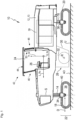
- FIG. 1 an embodiment of a soil cultivation machine according to the invention in the form of a large soil or road milling machine is generally designated 10. It comprises a machine frame 12, which forms the basic framework for a machine body 13.
- the machine body 13 comprises the machine frame 12 and components of the machine 10 which are connected to the machine frame 12 and are optionally movable relative to it.
- the machine body 13 comprises front lifting columns 14 and rear lifting columns 16, which are connected at one end to the machine frame 12 and at the other end to front drives 18 and rear drives 20. The distance of the machine frame 12 from the drives 18 and 20 can be changed by the lifting columns 14 and 16.
- the drives 18 and 20 are shown as track drives by way of example. Individual or all drives 18 and/or 20 can also be wheel drives.
- a machine longitudinal direction orthogonal to the cross machine direction Q is designated L and runs parallel to the plane of the drawing of Figure 1 .
- a machine height direction H also runs parallel to the drawing plane of Figure 1 and orthogonal to the machine longitudinal and cross machine directions L and Q respectively.
- the arrowhead of the machine longitudinal direction L in Figure 1 points in the forward direction.
- the machine height direction H is parallel to the yaw axis Gi of the machine 10
- the machine longitudinal direction L is parallel to the roll axis Ro
- the machine cross direction Q is parallel to the pitch axis Ni.
- the soil tillage machine 10 has a control platform 24 from which a machine operator can control the machine 10 via a control panel 26.
- a working assembly 28 is arranged under the machine frame 12, here for example as a milling assembly 28 with a milling roller 32 accommodated in a milling roller box 30, which can be rotated about a milling axis R running in the machine transverse direction Q in order to be able to remove subsoil material during soil cultivation starting from the contact surface AO of the subsoil U with a milling depth determined by the relative height of the machine frame 12.
- the milling roller 32 is therefore a working device within the meaning of the present application.
- the height adjustability of the machine frame 12 by the lifting columns 14 and 16 also serves to adjust the milling or general working depth of the machine 10 during soil cultivation.
- the milling drum 32 can be mounted on the machine frame 12 so that it can be adjusted in height relative to the latter.
- the soil cultivation machine 10 shown as an example is a large milling machine, for which the arrangement of the milling assembly 28 in the machine's longitudinal direction L between the front and rear drives 18 and 20 is typical.
- Such large milling machines or soil-removing machines in general can have a conveyor belt to transport removed soil material away from the machine 10.
- a conveyor belt, which is also generally present on the machine 10, is shown in the drawing for reasons of better clarity. Figure 1 not shown.
- the machine 10 has two lifting columns 14 and 16 in both its front end region and its rear end region, each with a running gear 18 and 20 connected to them.
- the front lifting columns 14 are coupled to the running gears 18 in a manner known per se by means of a running gear connection structure 34, for example a connecting fork that spans the running gear 18 in the transverse direction Q of the machine.
- the rear lifting columns 16 are connected to their respective running gear 20 via a running gear connection structure 36 that is identical to the running gear connection structure 34.
- the running gears 18 and 20 are essentially identical in construction and form the chassis 22 of the machine.
- the running gears 18 and 20 are motor-driven, generally by a hydraulic motor (not shown).
- the driving force source of the machine 10 is an internal combustion engine 39 mounted on the machine frame 12.
- the engine drives the milling drum 32 to rotate.
- the power of the internal combustion engine 39 also provides a hydraulic pressure reservoir on the machine 10, through which hydraulic motors and hydraulic actuators on the machine can be operated.
- the internal combustion engine 39 is therefore also the source of the driving force of the machine 10.
- the drive 18 with a running direction indicated by the double arrow D has a radially inner receiving and guide structure 38 on which a revolving running chain 40 is arranged and guided for revolving movement.
- the lifting column 14 and with it the running gear 18 can be rotated about a steering axis S by a steering device (not shown in detail).
- a steering device not shown in detail
- the lifting column 16 and with it the running gear 20 can be rotated about a steering axis parallel to the steering axis S by a steering device.
- the operator's platform 24 is covered by a protective roof structure 42 which can be raised and lowered by means of a motion guide 50 and which comprises a protective roof 44 which is connected to the machine frame 12 or machine body 13 via a front window arrangement 46 and a rear wall arrangement 48.
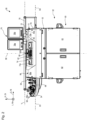
- control panel 26 is shown in the front view, i.e. from a viewing position of a machine operator operating the machine 10 in an operating area.
- the control panel 26 has a panel body 52 and a first control panel 54 that is movable relative to the panel body 52 along a movement path B1 parallel to the pitch axis Ni.
- the control panel 54 is located in Figure 2 in its operating position completely pulled out from a storage compartment 56 of the console body 52, in which all operating elements 58 arranged on the control panel 54 are accessible to the machine operator as intended.
- the desk body 52 is made of a material mix of metal on the one hand and robust plastic material with low density and thus low weight on the other hand, such as styrene-based plastic, possibly fiber-reinforced to further increase strength.
- the control panel which stands on a floor not shown in the drawing and is attached to it, is designed, for example, as a switch cabinet 60 for accommodating electrical circuits.
- This part is preferably made of metal.
- Two pivotable moving parts on a frame part 53 fixed to the control panel (see Figure 5 ) of the console body 52, hinged doors 62 and 63 close the control cabinet 60.
- the control panel 26 is essentially mirror-symmetrical with respect to a mirror symmetry plane SE parallel to the yaw axis Gi and the roll axis Ro.
- the soil tillage machine 10 can be operated using the operating elements 58 of the first operating panel 54.
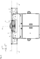
- the first control panel 54 is located along the movement path B1 through a stowage opening 64 on the Figure 2 left side of the upper part of the console body 52 along the pitch axis Ni completely into the console body 52. It is then located, as in Figure 2 not shown, in Figure 3 However, the second control panel 66 shown is completely housed in the storage compartment 56 provided for the first control panel 54 on the console body 52.
- the storage compartment 56 of the first control panel 54 is dome-shaped in its upper region 56a.
- This upper region 56a is preferably made of a composite material made of ASA and ABS.
- the stowage opening 64 can be closed by a cover 68 pivotally attached to the desk body 52.
- the cover 68 which is also preferably made of ASA or ABS is available in the Figures 2 and 3 in its open position and in Figure 4 shown in its locked position. In the locked position, the cover 68, as well as the cover 70 of the second control panel 66 opposite it on the opposite side of the console body 52, can be locked in order to secure the covers 68 and 70 against unauthorized opening and thus prevent unauthorized access to the control panels 54 and 66.
- a key 71, with which the second cover 70 can be locked, is in the Figures 2 , 4 and 5 shown.
- first and second control panels 54 and 66 can also be only partially pulled out of the console body 52 into an operating position if, for example, only a subset of the control elements 58 is required, which is arranged in the direction of extraction from the console body 52 at a leading end region of the control panels 54 and/or 66.
- control panels 54 and 66 can be pulled out of and inserted into their storage compartments 56 and 72, respectively, independently of one another.
- the console body 52 has in an area between the upper dome-shaped areas 56a and 72a (the dome-shaped upper area 72a is part of the storage compartment 72, which is designed according to the mirror symmetry described above for storing the Figure 3 shown second control panel 66 on the desk body 52) has an additional control panel 74 which is arranged in a fixed position on the desk body 52.
- the additional control panel 74 comprises a space-saving foil control panel 74a which can be arranged flat on the desk body 52 without protruding significantly outwards or inwards beyond an outer surface of the arrangement area on the desk body 52.
- the upper region 72a is also preferably made of ASA and/or ABS, as is the cover 70.
- the control panel 26 also has a display device 76 that is designed separately from the control panels 54 and 66 and also separately from the additional control panel 74.
- the display device 76 which has two display surfaces 76a and 76b, can be moved on a guide rail 78 along a displacement axis V that is parallel to the pitch axis Ni.
- the display device 76 can thus be moved along the pitch axis Ni to an operating location of the first control panel 54, to an operating location of the additional control panel 74 or to an operating location of the second control panel 66 and can display information there to the machine operator working at the time.
- the display surfaces 76a and 76b can also be designed to be touch-sensitive as a touchscreen for entering data.
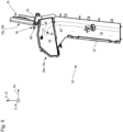
- the display device 76 is not only translationally displaceable along the guide rail 78, but is also rotatable around the guide rail 78 between its Figures 2 , 3 and 5 operating position shown and its Figure 4 shown protective position.
- the display device 76 In their operating position (see Figures 2 , 3 and 5 ), the display device 76 can be read as intended by a machine operator standing in the operating area in front of the control panel 26. In the protective position according to Figure 4 the display surfaces 76a and 76b of the display device 76 are located at a short distance from or preferably without a gap in relation to a counter surface 82 of the console body 52 having the additional control panel 74.
- the counter surface 82 of the desk body 52 is made of ASA and/or ABS, as are the housing parts of the display device 76, which face away from the desk body 52 in the protective position of the display device 76 and are therefore accessible.
- the areas 56a, 72a and 82 of the desk body 52 are preferably formed in one piece, particularly preferably by manufacturing them as a monolithic component without any joints for reasons of increased strength.
- the second control panel 66 which is also movable in translation relative to the console body 52, namely along a movement path B2 coaxial with the movement path B1 of the first control panel 54, is located in Figure 4 in its stowed position.
- the first control panel 54 is also in its stowed position, with the two covers 68 and 70 each in their locking positions and closing the respective stowage openings 64 and 65.
- Figure 4 thus shows an arrangement of the control panel 26 in which the control panel and its control panels 54, 66 and 74 as well as the display device 76 are maximally protected against vandalism attacks.
- control panel body 52 made of metal and/or plastic, in particular ASA and/or ABS, if desired with particle and/or fiber filling, can be overcome with sufficient force or criminal energy, an attacker needs considerably more time to seriously damage the control panel 26 than if the control panels were accessible without protection. A vandal must therefore accept over a longer period of time that he will generate noise while acting out his destructive rage and thus be discovered.
- a safety formation 84 connected to the display device 76 for joint movement is particularly clearly visible, which mainly extends parallel to the roll axis Ro, slightly angled to it, away from the display device 76.
- the safety formation 84 which is designed as a rod for example, is pivoted when the display device 76 is pivoted from its operating position into the position shown in Figure 4 shown protective position can be inserted into a safety recess 86 in the area of the additional control panel 74.
- the safety recess 86 is dimensioned such that the safety formation 84 can only be inserted into it when the display device 76 is located so precisely in the transverse center of the console body 52 that when pivoted about the guide rail 78 it comes to rest on the additional control panel 74 or on the counter surface 82 having the additional control panel 74.
- the display device 76 and the additional control panel 74 thus hide and protect each other from unauthorized access, in particular from violent access, when the display device 76 is in its protective position.
- the safety formation 84 has an eyelet 88 which extends parallel to the pitch axis Ni as a form-fitting formation.
- a fixing device 90 in the form of a rod is provided inside the console body 52.
- the cover 70 comes into contact with an actuating end 90a of the fixing device 90 when approaching its locking position.
- the fixing device 90 which is pre-tensioned into its release position in which it does not penetrate the safety recess 86, is released after the contact engagement with the cover 70 has been established by closing the cover 70 (transferring the cover into its Figure 2 shown blocking position) against the pre-tensioning force acting in the release position into the locking position, in which an engagement section 90b penetrates the securing recess 86.
- the engagement section 90a of the fixing device 90 in its fixing position penetrates the eyelet 88 of the securing formation 84 and thus creates a positive engagement which prevents the display device 76 from being displaced from the protective position reached.
- the control panel 26 is then almost hermetically sealed. All sensitive components necessary for machine operation are surrounded by the robust casing of the panel body 52 and are not immediately accessible to a violent attack.
- the fixing device 90 When the cover 70 is opened, the fixing device 90 is displaced by its pre-tension into the release position, in which the securing recess 86 and with it the eyelet 88 are no longer penetrated by the engagement section 90b. The display device 76 can then be brought back into its operating position.
- a convection heating device arranged inside the console body 52 is designated with 92 in dashed lines.
- the convection heating device essentially comprises a heating air line 94 which passes through the console body 52 to the floor.
- a further heating air line of the machine 10 which carries air that is warmer than the ambient air, can be connected to the heating air line 94. Heating air guided by the heating air line of the machine 10 can thus also be guided through the heating air line 94 of the control console 26 or the console body 52.
- Outlets of the convection heating device 92 are located inside the console body 52, behind the storage openings 64 and 65.
- the heating device 92 blows hot air through the storage openings 64 and 65 essentially parallel to the respective movement paths B1 and B2 in the direction away from the control console 26 over the surfaces of the control panels 54 and 66 equipped with control elements 58. In this way, a warm air area can be generated above the respective control panels 54 and/or 66, into which the machine operator immerses his hands when he reaches for control elements 58.
- the heating device 92 can be switched off entirely or with regard to a branch assigned to a control panel 54 or 66 in order to prevent hot air from flowing against a closed cover 68 or 70.
- the switch-off function can be implemented in a manner known per se by means of operable valves (not shown) or by means of a switchable fan.
Landscapes
- Engineering & Computer Science (AREA)
- Mechanical Engineering (AREA)
- Chemical & Material Sciences (AREA)
- Transportation (AREA)
- Combustion & Propulsion (AREA)
- Civil Engineering (AREA)
- Structural Engineering (AREA)
- Mining & Mineral Resources (AREA)
- Architecture (AREA)
- General Engineering & Computer Science (AREA)
- Component Parts Of Construction Machinery (AREA)
- Lifting Devices For Agricultural Implements (AREA)
- Physics & Mathematics (AREA)
- Thermal Sciences (AREA)
- Casings For Electric Apparatus (AREA)
- Mechanical Control Devices (AREA)
Description
Die vorliegende Erfindung betrifft eine Bodenbearbeitungsmaschine, wie etwa eine Straßenfräse, einen Recycler, einen Stabilisierer oder einen Surface-Miner. Die Bodenbearbeitungsmaschine hat ein Fahrwerk und einen vom Fahrwerk getragenen Maschinenrahmen. Sie weist eine Arbeitsvorrichtung zur Bodenbearbeitung auf. Am Maschinenrahmen ist ein Fahrstand mit einem Bedienpult zur Steuerung wenigstens einer Funktionseinrichtung der Bodenbearbeitungsmaschine vorgesehen. Das Bedienpult weist einen Pultkörper und ein relativ zum Pultkörper bewegliches Bedienpaneel mit wenigstens einem Bedienelement auf, welches einer Funktionseinrichtung zu dessen Steuerung zugeordnet oder zuordenbar ist.The present invention relates to a soil tillage machine, such as a road milling machine, a recycler, a stabilizer or a surface miner. The soil tillage machine has a chassis and a machine frame carried by the chassis. It has a working device for tilling the soil. A driver's station with a control panel for controlling at least one functional device of the soil tillage machine is provided on the machine frame. The control panel has a console body and a control panel that is movable relative to the console body and has at least one control element that is assigned or can be assigned to a functional device for controlling it.
Eine solche Bodenbearbeitungsmaschine in Gestalt einer Straßenfräse, insbesondere einer Straßengroßfräse, der Anmelderin ist im relevanten Markt unter der Produktbezeichnung "W 2200" bekannt. Diese Straßenfräse, wie andere Bodenbearbeitungsmaschinen auch, weist ein Bedienpult mit einem Pultkörper und einem vom Pultkörper getragenen Bedienpaneel auf, welches relativ zum Pultkörper beweglich ist, um es für den Maschinenführer, der es bedient, während der Betriebsphasen der Bodenbearbeitungsmaschine in eine ergonomisch vorteilhafte Position verbringen zu können.Such a soil tilling machine in the form of a road milling machine, in particular a large road milling machine, belonging to the applicant is known in the relevant market under the product name "W 2200". This road milling machine, like other soil tilling machines, has an operating console with a console body and an operating panel carried by the console body, which is movable relative to the console body in order to be able to move it into an ergonomically advantageous position for the machine operator who operates it during the operating phases of the soil tilling machine.
Immer häufiger treten bei Bodenbearbeitungsmaschinen in Phasen eines unbeobachteten Nichtgebrauchs Probleme mit Vandalismus auf. Unbefugte betreten dabei Baustellengelände und machen sich an den dort abgestellten Maschinen zu schaffen. Dabei versuchen manche auch, in den Fahrstand einer Bodenbearbeitungsmaschine zu gelangen. Diese Personen sind in der Regel nicht von technischer Neugier, sondern von Zerstörungswut getrieben, sodass großes Interesse besteht, leicht zerstörbare, empfindliche Baugruppen, wie etwa das oben genannte Bedienpaneel, möglichst vor einem Angriff durch Vandalen zu schützen.Vandalism is becoming more and more common with soil tillage machines when they are not in use without supervision. Unauthorized persons enter construction sites and tamper with the machines parked there. Some even try to get into the operator's cab of a soil tillage machine. These people are generally not driven by technical curiosity but by a desire for destruction, so there is a great interest in protecting easily destructible, sensitive components, such as the control panel mentioned above, from attack by vandals.
Die
Die Druckschrift
Die Druckschrift
Die Druckschrift
Die Druckschrift
Daher ist es Aufgabe der vorliegenden Erfindung, die Vandalismussicherheit der eingangs genannten Bodenbearbeitungsmaschine zu erhöhen.Therefore, it is an object of the present invention to increase the vandalism security of the soil tillage machine mentioned above.
Diese Aufgabe wird erfindungsgemäß gelöst durch eine Bodenbearbeitungsmaschine mit allen Merkmalen des Anspruchs 1. Bei einer solchen Bodenbearbeitungsmaschine ist unter anderem das Bedienpaneel in eine Verstauungsstellung verlagerbar, in der das wenigstens eine Bedienelement durch einen Abschnitt des Pultkörpers bedeckt ist, wobei das Bedienpaneel aus der Verstauungsstellung in eine Bedienstellung verlagerbar ist, in welcher wenigstens ein Bedienelement von dem Abschnitt unbedeckt und daher für seine Bedienung durch einen Maschinenführer zugänglich ist.This object is achieved according to the invention by a soil tillage machine with all the features of claim 1. In such a soil tillage machine, the control panel can be displaced, among other things, into a stowed position in which the at least one control element is covered by a section of the console body, wherein the control panel can be displaced from the stowed position into an operating position in which at least one control element is uncovered by the section and is therefore accessible for operation by a machine operator.
Somit kann die Zugänglichkeit des wenigstens einen Bedienelements des Bedienpaneels, vorzugsweise jedoch des gesamten Bedienpaneels in dessen Verstauungsstellung für Unbefugte erschwert werden.Thus, the accessibility of at least one control element of the control panel, but preferably of the entire control panel in its stowed position, can be made more difficult for unauthorized persons.
Der Pultkörper ist dabei jener Körper der Bodenbearbeitungsmaschine (oder nachfolgend auch nur kurz als "Maschine" bezeichnet), mit welchem das Bedienpaneel relativbeweglich verbunden ist und von welchem das Bedienpaneel getragen ist. Der Pultkörper kann folglich wenigstens teilweise oder sogar vollständig vom Maschinenrahmen oder/und von einem Fahrstandrahmen gebildet sein. Beispielsweise kann ein Boden des Pultkörpers vom Maschinenrahmen oder - im Falle eines relativ zum Maschinenrahmen verlagerbaren Fahrstands - von einem Fahrstandrahmen oder von einem Fahrstandboden gebildet sein. Um Missverständnissen vorzubeugen, sei an dieser Stelle klargestellt, dass vorliegend unter einem relativ zum Maschinenrahmen verlagerbaren Fahrstand lediglich ein aktiv verlagerbarer Fahrstand bezeichnet ist, welcher entweder durch entsprechende Aktuatoren oder manuell durch den Maschinenführer zwischen zwei unterschiedlichen Relativposition relativ zum Maschinenrahmen verlagerbar ist. Fahrstandböden, die in an sich bekannter Weise unter Zwischenanordnung einer Vibrationsdämpfung lediglich passiv-mikrobeweglich mit dem Maschinenrahmen verbunden sind, sind maschinenrahmenfeste Fahrstandböden im Sinne der vorliegenden Anmeldung.The console body is the body of the soil tillage machine (or hereinafter referred to as "machine" for short) to which the control panel is connected in a relatively movable manner and by which the control panel is carried. The console body can therefore be formed at least partially or even completely by the machine frame and/or by a driver's station frame. For example, a floor of the console body can be formed by the machine frame or - in the case of a driver's station that can be moved relative to the machine frame - by a driver's station frame or by a driver's station floor. To avoid misunderstandings, it should be clarified at this point that in the present case a driver's station that can be moved relative to the machine frame only refers to an actively movable driver's station that can be moved between two different relative positions relative to the machine frame either by corresponding actuators or manually by the machine operator. Driver's station floors that are connected to the machine frame in a manner known per se in a merely passive, micro-movable manner with the interposition of a vibration damper are driver's station floors that are fixed to the machine frame within the meaning of the present application.
Bevorzugt ist der Pultkörper jedoch wenigstens abschnittsweise gesondert vom Maschinenrahmen oder/und Fahrstandrahmen ausgebildet. Hierdurch kann für den gesondert ausgebildeten Abschnitt des Pultkörpers wenigstens abschnittsweise ein Material gewählt werden, welches für den Einsatz als Pultkörper ausreichend robust, jedoch von geringerer Dichte als das für den Maschinenrahmen oder/und den Fahrstandrahmen verwendete Material ist. Bevorzugt ist der Pultkörper zumindest abschnittsweise aus Kunststoff oder/und Metall gebildet. Ein Pultkörperabschnitt aus Kunststoff, insbesondere aus partikel- oder/und faserverstärktem Kunststoff, weist bei vorgegebenem Bauvolumen ein vorteilhaft niedriges Gewicht bei gleichzeitig hoher Festigkeit und hoher Kerbschlagzähigkeit auf. Als Kunststoff mit hoher Vandalismusfestigkeit kann bevorzugt ein auf Acrylnitril und Styrol basierender Kunststoff oder Kunststoffverbund verwendet werden, etwa Acrylester-Styrol-Acrylnitril (ASA) oder/und Acrylnitril-Butadien-Styrol (ABS). Besonders bevorzugt wird zur Nutzung der vorteilhaften Eigenschaften beider Materialien ein Verbundwerkstoff, umfassend ASA und ABS, verwendet. Dabei liegt das stärker witterungs- und wärmeformbeständigere ASA bevorzugt außen. Ein Pultkörperabschnitt aus Metall weist ebenfalls eine hohe Festigkeit auf und kann besonders vorteilhaft von Teilen des in der Regel ebenfalls aus Metall gebildeten Maschinenrahmens gebildet sein oder besonders dauerhaft mit Abschnitten des Maschinenrahmens aus Metall verbunden werden, etwa durch Schweißen.Preferably, however, the desk body is designed separately from the machine frame and/or the operator's platform frame at least in sections. This means that a material can be selected for the separately designed section of the desk body at least in sections which is sufficiently robust for use as a desk body, but of lower density than the material used for the machine frame and/or the operator's platform frame. Preferably, the desk body is made at least in sections from plastic and/or metal. A desk body section made of plastic, in particular particle and/or fiber-reinforced plastic, has an advantageously low weight for a given construction volume while at the same time being high in strength and high in impact strength. A plastic or plastic composite based on acrylonitrile and styrene can preferably be used as a plastic with high vandalism resistance, such as acrylic ester-styrene-acrylonitrile (ASA) and/or acrylonitrile-butadiene-styrene (ABS). A composite material comprising ASA and ABS is particularly preferably used to utilize the advantageous properties of both materials. The ASA, which is more weather-resistant and heat-resistant, is preferably placed on the outside. A metal console body section also has a high level of strength and can be particularly advantageously formed from parts of the machine frame, which is usually also made of metal, or can be particularly permanently connected to sections of the machine frame made of metal, for example by welding.
Das Bedienpaneel kann zur Erzielung eines möglichst geringen Gewichts einen geschäumten Kunststoff umfassen, insbesondere geschäumtes Polyurethan. Dieser Werkstoff weist eine besonders vorteilhafte mechanische innere Dämpfung auf. Dies ist gerade beim Einsatz in stark vibrationsbelasteten Bodenbearbeitungsmaschinen, wie es beispielsweise Straßenfräsen sind, von Vorteil. Bevorzugt umfasst ein Grundkörper des Bedienpaneels den geschäumten Kunststoff. Ein darauf angeordnetes Bedienelement kann aus einem abweichenden Kunststoff oder/und aus Metall gebildet sein.To achieve the lowest possible weight, the control panel can comprise a foamed plastic, in particular foamed polyurethane. This material has particularly advantageous mechanical internal damping. This is particularly advantageous when used in soil tillage machines subject to high levels of vibration, such as road milling machines. A base body of the control panel preferably comprises the foamed plastic. A control element arranged on it can be made of a different plastic and/or metal.
Da der Pultkörper über die bloße Halterung des Bedienpaneels hinaus weitere Aufgaben, wie etwa die Bereitstellung abschließbaren Stauraums, erfüllen kann, umfasst der Pultkörper vorteilhafterweise einen fahrstandfesten Gestellteil und - über das Bedienpaneel hinaus - wenigstens ein beweglich daran gelagertes Bewegungsteil. Der das Bedienpaneel in dessen Verstauungsstellung bedeckende Pultkörper-Abschnitt ist aus Gründen höherer Stabilität und höheren Widerstands gegen äußere Krafteinwirkung bevorzugt Bestandteil des fahrstandfesten Gestellteils.Since the console body can perform other tasks beyond simply holding the control panel, such as providing lockable storage space, the console body advantageously comprises a frame part fixed to the driver's position and - in addition to the control panel - at least one moving part movably mounted on it. The console body section that covers the control panel in its stowed position is preferably part of the frame part fixed to the driver's position for reasons of greater stability and greater resistance to external forces.
Aus Gründen effizienter Bauraumausnutzung ist der das Bedienpaneel in der Verstauungsstellung bedeckende Abschnitt des Pultkörpers bevorzugt ein Wandabschnitt einer Gehäusewand des Pultkörpers. Aus Gründen möglichst hoher Festigkeit gegen Gewalteinwirkung bei gleichzeitig nicht übermäßiger Materialdichte und damit Bauteilgewicht, ist bevorzugt der das Bedienpaneel in der Verstauungsstellung bedeckende Abschnitt des Pultkörpers, wie oben dargelegt, aus Kunststoff, insbesondere aus dem ASA-ABS-Verbundwerkstoff gebildet.For reasons of efficient use of installation space, the section of the console body covering the control panel in the stowed position is preferably a wall section of a housing wall of the console body. For reasons of the highest possible strength against the effects of force while at the same time not excessive material density and thus component weight, the section of the console body covering the control panel in the stowed position is preferably made of plastic, in particular of the ASA-ABS composite material, as explained above.
Grundsätzlich kann daran gedacht sein, dass das Bedienpaneel in seiner Verstauungsstellung von dem Abschnitt des Pultkörpers überspannt wird, wobei der überspannende Abschnitt an einem oder an seinen beiden Endbereichen mit dem Bedienpaneel verbunden sein kann. Beispielsweise kann das Bedienpaneel beweglich an dem Abschnitt zur Relativbewegung mit diesem geführt sein, sodass es in seiner Verstauungsstellung von dem Abschnitt bedeckt ist und zur Verlagerung in die Bedienstellung von unter dem Wandabschnitt hervorgezogen werden kann. In diesem Falle kann das Bedienpaneel dann, wenn es sich in seiner Verstauungsstellung befindet, zusammen mit dem es bedeckenden Pultkörper-Abschnitt einen geschlossenen Wandbereich bilden, welcher eine Zugänglichkeit des wenigstens einen Bedienelements verhindert. Allerdings wäre eine Seite des Bedienpaneels vom Pultkörper nicht überspannt und somit auch in der Verstauungsstellung erreichbar. Da sich im Bedienpaneel sensible Elektronik befinden kann, welche Steuerungsbefehle von dem wenigstens einen Bedienelement erfassen und zu einer Maschinensteuerung weiterleiten kann, ist es vorteilhaft, wenn sich das Bedienpaneel in seiner Verstauungsstellung vollständig im Pultkörper befindet.In principle, it can be envisaged that the control panel is spanned by the section of the desk body in its stowed position, whereby the spanning section can be connected to the control panel at one or both of its end areas. For example, the control panel can be movably guided on the section for relative movement with it, so that it is covered by the section in its stowed position and can be pulled out from under the wall section to be moved into the operating position. In this case, when the control panel is in its stowed position, it can form a closed wall area together with the desk body section covering it, which prevents access to at least one control element. However, one side of the control panel would not be spanned by the desk body and would therefore also be accessible in the stowed position. Since the control panel may contain sensitive electronics which can detect control commands from at least one control element and forward them to a machine control system, it is advantageous if the control panel is completely located in the console body in its stowed position.
Somit kann zu einer Erzielung eines möglichst hohen Vandalismusschutzes des Bedienpaneels vorgesehen sein, dass der Pultkörper eine Verstauungsöffnung aufweist, durch welche hindurch das Bedienpaneel derart in die Verstauungsstellung verlagerbar ist, dass das Bedienpaneel in seiner Verstauungsstellung vollständig im Pultkörper aufgenommen ist. Der Pultkörper kann gleichsam ein Verstauungsfach aufweisen, in welches hinein das Bedienelement, ohne es vom Pultkörper zu trennen, in seine Verstauungsstellung verbracht werden kann.Thus, in order to achieve the highest possible protection against vandalism of the control panel, the console body can be provided with a stowage opening through which the control panel can be moved into the stowed position in such a way that the control panel is completely accommodated in the console body in its stowed position. The console body can also have a stowage compartment into which the control element can be moved into its stowed position without separating it from the console body.
Dann, wenn das Bedienpaneel, wie es häufig der Fall sein wird, eine im Wesentlichen flächige, insbesondere ebene Platte ist, deren Dickenabmessung wesentlich kleiner ist als ihre Abmessungen in den Haupterstreckungsrichtungen der flächigen Platte, kann bereits eine verhältnismäßig kleine und den Querschnittsabmessungen des Bedienpaneels - bei Betrachtung eines Querschnitts in einer zur Bewegungsbahn zwischen Verstauungsstellung und Bedienstellung orthogonalen Schnittebene - angepasste Verstauungsöffnung den Zugang zum Bedienpaneel in dessen Verstauungsstellung ausreichend erschweren.If, as will often be the case, the control panel is a substantially flat, in particular planar plate, the thickness of which is significantly smaller than its dimensions in the main directions of extension of the planar plate, even a relatively small stowage opening adapted to the cross-sectional dimensions of the control panel - when considering a cross-section in a cutting plane orthogonal to the path of movement between the stowed position and the operating position - can make access to the control panel in its stowed position sufficiently difficult.
Häufig trägt das Bedienpaneel jedoch wenigstens ein körperlich ausladendes Bedienelement, wie einen Bedienhebel (Joystick), welcher vom Bedienpaneel weg absteht, wobei dessen gelenkige Anbindung an das Bedienpaneel wiederum durch einen ebenfalls körperlich ausladenden Balg abgedeckt sein kann. Ein solcher Bedienhebel muss zur Verlagerung des Bedienpaneels in seine Verstauungsstellung ebenfalls durch die Verstauungsöffnung hindurch bewegt werden können. Dies setzt einer Verkleinerung der Verstauungsöffnung im Pultkörper Grenzen.However, the control panel often carries at least one physically protruding control element, such as a control lever (joystick), which protrudes from the control panel, whereby its articulated connection to the control panel is in turn ensured by a likewise physically can be covered by a protruding bellows. Such an operating lever must also be able to be moved through the stowage opening in order to move the control panel into its stowage position. This limits the possibility of reducing the stowage opening in the console body.
Zur weiteren Erhöhung einer Unzugänglichkeit des Bedienpaneels in dessen Verstauungsstellung weist daher das Bedienpult gemäß einer vorteilhaften Weiterbildung der vorliegenden Erfindung einen zwischen einer Öffnungsstellung und einer Sperrstellung beweglichen Deckel auf, welcher in seiner Sperrstellung die Verstauungsöffnung verschließt und so das in die Verstauungsstellung verlagerte Bedienpaneel gegen einen unbefugten Zugriff und folglich gegen eine unerwünschte Verlagerung aus der Verstauungsstellung sichert. In seiner Öffnungsstellung gibt der Deckel die Verstauungsöffnung für eine Bewegung des Bedienpaneels frei. Der Deckel kann ein Beispiel für ein oben genanntes Bewegungsteil des Pultkörpers sein. Bevorzugt ist der Deckel unverlierbar am Pultkörper angeordnet, insbesondere schwenkbar angelenkt. Es soll jedoch nicht ausgeschlossen sein, dass der Deckel zur Verbringung in seine Öffnungsstellung insgesamt vom Pultkörper abnehmbar ist.To further increase the inaccessibility of the control panel in its stowed position, the control panel according to an advantageous development of the present invention has a cover that can be moved between an open position and a locked position, which in its locked position closes the stowage opening and thus secures the control panel moved into the stowed position against unauthorized access and consequently against unwanted movement from the stowed position. In its open position, the cover releases the stowage opening for movement of the control panel. The cover can be an example of an above-mentioned moving part of the console body. The cover is preferably arranged captively on the console body, in particular pivotally attached. However, it should not be ruled out that the cover can be removed from the console body in its entirety in order to be moved into its open position.
Bevorzugt ist der Deckel wenigstens in seiner Sperrstellung unter Verwendung eines Schließgeheimnisses, wie Schlüssel oder Magnetcode und dergleichen, absperrbar, sodass die Verstauungsöffnung weiter gegen ein gewaltsames Öffnen gesichert werden kann. Zumindest kann die Zeitdauer, die ein Vandale benötigt, um sich gewaltsam Zugang zu dem bestimmungsgemäß verstauten Bedienpaneel zu verschaffen, erheblich erhöht werden, was erfahrungsgemäß die Chance des Bedienpaneels auf Unversehrtheit bei einem Vandalismusangriff erhöht.Preferably, the lid can be locked at least in its locked position using a secret lock, such as a key or magnetic code and the like, so that the stowage opening can be further secured against being opened by force. At the very least, the amount of time a vandal needs to gain violent access to the control panel that has been stowed away as intended can be significantly increased, which experience shows increases the chance of the control panel remaining intact in the event of a vandal attack.
Das wenigstens eine Bedienelement des Bedienpaneels kann eine beliebige Funktionseinrichtung der Bodenbearbeitungsmaschine steuern, wie etwa den Antrieb oder/und die Lenkung oder/und die Arbeitsvorrichtung oder/und die Lage und Orientierung des Maschinenrahmens relativ zum Untergrund, auf welchem die Maschine aufsteht oder/und Unterstützungsvorrichtungen, wie etwa Gebläse, Bewässerungsanlagen, Transportvorrichtungen und dergleichen. Üblicherweise wird ein Bedienpaneel mehr als ein Bedienelement aufweisen, um damit eine Vielzahl von Funktionseinrichtungen steuern zu können. Das wenigstens eine Bedienelement kann einen Kippschalter oder/und einen Drehschalter oder/und eine Taste oder/und ein Tastenfeld oder/und einen mehrachsigen Bedienhebel (Joystick) oder/und dergleichen umfassen.The at least one control element of the control panel can control any functional device of the soil cultivation machine, such as the drive and/or the steering and/or the working device and/or the position and orientation of the machine frame relative to the ground on which the machine stands and/or support devices, such as fans, irrigation systems, transport devices and the like. A control panel will usually have more than one control element in order to be able to control a large number of functional devices. The at least one control element can comprise a toggle switch and/or a rotary switch and/or a button and/or a keypad and/or a multi-axis control lever (joystick) and/or the like.
Häufig ist der auf der Bodenbearbeitungsmaschine arbeitende Maschinenführer während seiner Tätigkeit wenigstens eingeschränkt der Witterung ausgesetzt. Auf dem Fahrstand herrscht dabei häufig Umgebungstemperatur, was gerade im Winter und in den Übergangszeiten auf die Dauer für den Maschinenführer unangenehm sein kann. Zur Erhöhung des Arbeitskomforts des Maschinenführers ist es daher vorteilhaft, wenn das Bedienpult eine Konvektions-Heizvorrichtung umfasst, welche dazu ausgebildet ist, Heizluft mit einer höheren Temperatur als die Umgebungslufttemperatur zu dem in die Bedienstellung verlagerten Bedienpaneel zu leiten. Die in der Konvektions-Heizvorrichtung transportierte Heizluft kann mittels Wärmetauscher durch Abwärme einer Brennkraftmaschine oder eines anderen sich im Betrieb erwärmenden Funktionseinrichtung erwärmt werden.The machine operator working on the soil tillage machine is often exposed to the weather to at least a limited extent during his work. The operating platform is often at ambient temperature, which can be unpleasant for the machine operator in the long term, particularly in winter and in the transitional periods. To increase the working comfort of the machine operator, it is therefore advantageous if the control panel includes a convection heating device which is designed to direct hot air at a higher temperature than the ambient air temperature to the control panel which has been moved to the operating position. The hot air transported in the convection heating device can be heated by means of a heat exchanger using waste heat from an internal combustion engine or another functional device which heats up during operation.
Die Heizluft führende Heizleitung kann dann vorteilhaft vollständig im Pultkörper aufgenommen sein. Sie ist daher von außen nicht zugänglich. Bevorzugt ist die Konvektions-Heizvorrichtung dazu ausgebildet, Heizluft von einem das Bedienpaneel in seiner Verstauungsstellung aufnehmenden Staubereich des Bedienpults, insbesondere des Pultkörpers, zu dem in die Bedienstellung verlagerten Bedienpaneel zu leiten.The heating line carrying the hot air can then advantageously be completely accommodated in the console body. It is therefore not accessible from the outside. The convection heating device is preferably designed to guide hot air from a storage area of the console, in particular the console body, which accommodates the control panel in its stowed position, to the control panel moved into the operating position.
Die Konvektions-Heizvorrichtung kann gemäß einer vorteilhaften Weiterbildung dazu ausgebildet sein, dann, wenn sich das Bedienpaneel in einer Bedienstellung befindet, wenigstens ein Bedienelement mit gegenüber der Umgebungsluft erwärmten Luft anzublasen, sodass das wenigstens eine angeblasene Bedienelement erwärmt werden kann. Üblicherweise wird dadurch auch in der Umgebung des wenigstens einen Bedienelements ein Strom erwärmter Luft bereitgestellt, sodass der Maschinenführer, wenn er mit seinen Händen nach dem wenigstens einen angeblasenen Bedienelement greift, in einen Luftstrom erwärmter Luft eintauchen kann. In dem bevorzugten Fall eines flächigen Bedienpaneels kann ein vorteilhaft großer Raum an und über der wenigstens ein Bedienelement tragenden Seite des Bedienpaneels durch den Luftstrom erwärmter Luft beströmt werden, wenn die Konvektions-Heizvorrichtung dazu ausgebildet ist, erwärmte Luft über das in eine Bedienstellung verlagerte flächige Bedienelement im Wesentlichen parallel zu dessen Flächenerstreckung auszublasen.According to an advantageous development, the convection heating device can be designed to blow air that is warmer than the ambient air onto at least one control element when the control panel is in an operating position, so that the at least one blown control element can be heated. This usually also provides a flow of heated air in the vicinity of the at least one control element, so that the machine operator can immerse himself in a flow of heated air when he reaches for the at least one blown control element with his hands. In the preferred case of a flat control panel, an advantageously large space on and above the side of the control panel that carries at least one control element can be flowed through by the flow of heated air if the convection heating device is designed to blow heated air out over the flat control element that has been moved into an operating position, essentially parallel to its surface extension.
Besonders vorteilhaft kann dann, wenn sich das Bedienpaneel in seiner Verstauungsstellung vollständig im Pultkörper befindet, die Verstauungsöffnung zur Ausgabe erwärmter Luft genutzt werden. Die Konvektions-Heizvorrichtung ist daher bevorzugt dazu ausgebildet, die Heizluft durch die genannte Verstauungsöffnung hindurch zu dem in die Bedienstellung verlagerten Bedienpaneel auszugeben. Eine Ausgabedüse der Konvektions-Heizvorrichtung kann dabei im Inneren des Pultkörpers gelegen sein, also vom Fahrstand aus betrachtet hinter der Verstauungsöffnung des Pultkörpers, sodass auch die Ausgabedüse durch den oben genannten Deckel für Phasen des Nicht-Gebrauchs der Maschine abgedeckt und unzugänglich gemacht werden kann.When the control panel is in its stowed position completely in the console body, the stowage opening can be used to dispense heated air, which is particularly advantageous. The convection heating device is therefore preferably designed to dispense the heated air through the stowage opening mentioned to the control panel that has been moved into the operating position. An output nozzle of the convection heating device can be located inside the console body, i.e. behind the stowage opening of the console body when viewed from the driver's position, so that the output nozzle can also be covered and made inaccessible by the above-mentioned cover for phases when the machine is not in use.
Da es bei einer translatorischen Verlagerung ausreichen kann, das Bedienpaneel zwar aus der Verstauungsstellung, aber nicht vollständig aus dem Pultkörper heraus zu verlagern, um die Maschine in wenigstens einem eingeschränkten, aber für einen konkreten Einsatzfall ausreichenden Umfang bedienen zu können, ist erfindungsgemäß vorgesehen, dass das Bedienpaneel translatorisch zwischen der Bedienstellung und der Verstauungsstellung verlagerbar ist.Since, in the case of a translational displacement, it may be sufficient to move the control panel out of the stowed position but not completely out of the console body in order to be able to operate the machine to at least a limited extent that is sufficient for a specific application, the invention provides that the control panel can be moved translationally between the operating position and the stowed position.
Sind beispielsweise Fahrhebel an einem bei einer Verlagerung des Bedienpaneels aus der Verstauungsstellung heraus vorauseilenden Randbereich des Bedienpaneels vorgesehen, dann kann durch bereits geringfügiges Herausziehen des Bedienpaneels aus dem Pultkörper ein Fahrbetrieb der Maschine ermöglicht werden. Beispielsweise kann es für ein Verladen der Maschine auf einen Tieflader für einen Versand-Transport ausreichen, wenn lediglich Fahrgeschwindigkeit und Fahrtrichtung der Maschine steuerbar sind, nicht jedoch die Arbeitsvorrichtung und Unterstützungsvorrichtungen derselben. Bevorzugt ist das Bedienpaneel über einen Kabel- oder Leitungsschlepp mit einer Steuereinrichtung oder einer Signalleitung im Inneren des Bedienpult verbunden, sodass unabhängig von der Relativstellung des Bedienpaneels zum Pultkörper stets Steuerungseingaben an dem wenigstens einen Bedienelement zu einer Maschinensteuerung übertragen werden können.If, for example, driving levers are provided on an edge area of the control panel that is in front when the control panel is moved out of the stowed position, then the machine can be driven by pulling the control panel out of the console body even slightly. For example, when loading the machine onto a low-loader for shipping, it may be sufficient if only the machine's driving speed and direction of travel can be controlled, but not its working device and support devices. The control panel is preferably connected to a control device or a signal line inside the control console via a cable or line trailing device, so that control inputs on the at least one control element can always be transmitted to a machine control system regardless of the relative position of the control panel to the console body.
Bei Bodenbearbeitungsmaschinen, insbesondere bei Straßenfräsen, ist es häufig besonders wichtig, dass der Maschinenführer die Maschine möglichst nah an ihrem Maschinen-Seitenrand bedienen kann, etwa um einen Bearbeitungs-Endbereich der Arbeitsvorrichtung und das damit erzielte Bearbeitungsergebnis überwachen zu können. Daher ist bevorzugt das Bedienpaneel parallel zu einer parallel zur Maschinenquerrichtung verlaufenden Nickachse der Bodenbearbeitungsmaschine translatorisch zwischen Verstauungsstellung und einer Bedienstellung verlagerbar. Somit kann der Maschinenführer mit einer translatorischen Verlagerung des Bedienpaneels aus seiner Verstauungsstellung heraus das Bedienpaneel längs der Nickachse einem Seitenrand der Maschine annähern.With soil tillage machines, particularly road milling machines, it is often particularly important that the machine operator can operate the machine as close to the side edge of the machine as possible, for example in order to be able to monitor the end of the working area of the working device and the processing result achieved with it. Therefore, the control panel can preferably be moved in a translational manner between the stowed position and an operating position parallel to a pitch axis of the soil tillage machine that runs parallel to the machine's transverse direction. The machine operator can thus move the control panel along the pitch axis closer to a side edge of the machine by moving the control panel in a translational manner from its stowed position.
Um gewährleisten zu können, dass eine Maschine an beiden Seitenrändern, also an beiden Endbereichen der Maschine längs der Nickachse, vom Maschinenführer bedienbar ist, kann daran gedacht sein, dass ein Bedienpaneel über eine sehr lange Strecke durch den Pultkörper hindurch verlagerbar ist. Der Pultkörper kann dann zwei längs der Bewegungsbahn des Bedienpaneels mit Abstand voneinander angeordnete Verstauungsöffnungen aufweisen, wobei das Bedienpaneel durch jede dieser Verstauungsöffnungen in den Pultkörper hinein und aus diesem heraus bewegt werden kann. Allerdings ist dabei die Breite des Pultkörpers, insbesondere der Abstand der beiden Verstauungsöffnungen voneinander, begrenzt, da ein und dasselbe Bedienpaneel im Pultkörper von beiden Verstauungsöffnungen ausgehend für den Maschinenführer erreichbar sein muss. Vorteilhafter ist es daher, wenn das Bedienpult zwei Bedienpaneele aufweist, welche unabhängig voneinander an unterschiedlichen Orten des Pultkörpers in je eine Verstauungsstellung bringbar sind, an welcher sie von je einem Pultkörper-Abschnitt bedeckt sind. Bevorzugt sind beide Bedienpaneele unabhängig voneinander durch je eine Verstauungsöffnung zur Verlagerung in ihre Verstauungsstellung in den Pultkörper einführbar. Die beiden Verstauungsöffnungen befinden sich bevorzugt mit Abstand voneinander an entgegengesetzten Seiten des Pultkörpers.In order to ensure that a machine can be operated by the machine operator on both side edges, i.e. at both end areas of the machine along the pitch axis, it can be considered that a control panel can be moved over a very long distance through the console body. The console body can then have two stowage openings arranged at a distance from one another along the movement path of the control panel, whereby the control panel can be moved into and out of the console body through each of these stowage openings. However, the width of the console body, in particular the distance between the two stowage openings, is limited, since one and the same control panel in the console body must be accessible to the machine operator from both stowage openings. It is therefore more advantageous if the control console has two control panels which can be brought into a stowage position independently of one another at different locations on the console body, in which they are each covered by a section of the console body. Preferably, both control panels can be inserted independently of one another through a stowage opening in the console body for relocation to their stowage position. The two stowage openings are preferably located at a distance from one another on opposite sides of the console body.
Für das zweite oder weitere Bedienpaneel und dessen Ausgestaltung und Anordnung sowie Beweglichkeit gilt das oben zum Bedienpaneel Gesagte entsprechend. Die beiden Bedienpaneele, welche bevorzugt längs einer koaxialen Bewegungsbahn zwischen ihren jeweiligen Stellungen: Verstauungsstellung und Bedienstellung, unabhängig voneinander beweglich sind, sind bevorzugt an entgegengesetzten Seiten des Pultkörpers aus diesem heraus aus ihrer jeweiligen Verstauungsstellung verlagerbar. So kann jedes der Bedienpaneele bei Verlagerung in eine Bedienstellung einem anderen von zwei entgegengesetzten Seitenrändern der Maschine angenähert werden. Die Verwendung von zwei Bedienpaneelen ermöglicht außerdem eine Anpassung der Anordnung des wenigstens einen Bedienelements auf dem jeweiligen Bedienpaneel an den dem Bedienpaneel zugeordneten Bedienort. So können die beiden Bedienpaneele beispielsweise bezüglich einer zur Rollachse (Maschinenlängsachse) und zur Gierachse (Maschinenhochachse) der Maschine parallelen Symmetrieebene spiegelsymmetrisch ausgebildet sein. Insbesondere kann eine Mehrzahl von Bedienelementen entsprechend spiegelsymmetrisch auf den Bedienpaneelen angeordnet sein.What was said above about the control panel applies accordingly to the second or further control panel and its design, arrangement and mobility. The two control panels, which are preferably movable independently of one another along a coaxial movement path between their respective positions: stowed position and operating position, are preferably displaceable on opposite sides of the console body from their respective stowed position. Thus, when moved to an operating position, each of the control panels can be brought closer to another of two opposite side edges of the machine. The use of two control panels also enables the arrangement of the at least one control element on the respective control panel to be adapted to the operating location assigned to the control panel. For example, the two control panels can be designed to be mirror-symmetrical with respect to a plane of symmetry parallel to the roll axis (machine longitudinal axis) and the yaw axis (machine vertical axis) of the machine. In particular, a plurality of control elements can be arranged mirror-symmetrically on the control panels.
Zur Rückmeldung an den Maschinenführer sowie gegebenenfalls auch zur Eingabe von Daten kann das Bedienpult eine Anzeigevorrichtung aufweisen. Eine Anzeigevorrichtung kann Teil des Bedienpaneels sein. Bevorzugt weist die Maschine eine von dem wenigstens einen Bedienpaneel gesondert ausgebildete Anzeigevorrichtung auf. Auch die Anzeigevorrichtung kann zum Schutz vor Vandalismusangriffen in Zeiten des Nicht-Gebrauchs der Maschine relativ zum Pultkörper bewegbar sein zwischen einer Betriebsstellung, in welcher eine Anzeigefläche der Anzeigevorrichtung derart zu einem vor dem Bedienpult gelegenen Bedienbereich weist, dass sie von einem Maschinenführer ablesbar ist, und einer Schutzstellung, in welcher die Anzeigefläche einer Gegenfläche des Pultkörpers gegenüberliegt.The control panel can have a display device to provide feedback to the machine operator and, if necessary, also to enter data. A display device can be part of the control panel. The machine preferably has a display device that is designed separately from the at least one control panel. To protect against vandalism when the machine is not in use, the display device can also be movable relative to the panel body between an operating position in which a display surface of the display device faces an operating area located in front of the control panel in such a way that it can be read by a machine operator, and a protective position in which the display surface is opposite a counter surface of the panel body.
Ganz grundsätzlich kann die Anzeigevorrichtung translatorisch zwischen der Betriebsstellung und der Schutzstellung bewegbar sein. Da ein Schutz der Anzeigefläche bei nicht-Gebrauch der Maschine jedoch durch Herstellen einer Gegenüberstellung von Anzeigefläche und Gegenfläche des Pultkörpers erzielt werden soll, ist bevorzugt die Anzeigevorrichtung zwischen ihrer Betriebsstellung und ihrer Schutzstellung schwenkbar. Bevorzugt ist eine Schwenkachse, um welche die Schwenkbewegung zwischen Betriebsstellung und Schutzstellung erfolgt, parallel zur Nickachse und damit auch parallel zu der bevorzugten translatorischen Bewegungsbahn des wenigstens einen Bedienpaneels.In principle, the display device can be moved in a translational manner between the operating position and the protective position. However, since protection of the display surface when the machine is not in use is to be achieved by creating a position opposite the display surface and the counter surface of the console body, the display device is preferably pivotable between its operating position and its protective position. Preferably, a pivot axis, around which the pivoting movement between the operating position and the protective position takes place, is parallel to the pitch axis and thus also parallel to the preferred translational movement path of the at least one control panel.
Zum Schutz der Anzeigefläche der Anzeigevorrichtung, wobei die Anzeigefläche aus mehreren gesonderten Anzeige-Teilflächen gebildet sein kann, ist das Spaltmaß zwischen Anzeigevorrichtung und Gegenfläche in der Schutzstellung der Anzeigevorrichtung möglichst gering, vorzugsweise geringer als 5 mm. Um einen Hebelansatz in einem zwischen Anzeigevorrichtung und Gegenfläche in der Schutzstellung der Anzeigevorrichtung gebildeten Spalt möglichst vermeiden zu können, sollte das Spaltmaß zwischen Anzeigevorrichtung und Gegenfläche sogar weniger als 2 mm betragen. Besonders bevorzugt liegt die Anzeigevorrichtung in der Schutzstellung spaltfrei in Anlageeingriff an der Gegenfläche an.To protect the display surface of the display device, where the display surface can be formed from several separate display sub-surfaces, the gap between the display device and the counter surface in the protective position of the display device is as small as possible, preferably less than 5 mm. In order to be able to avoid lever engagement in a gap formed between the display device and the counter surface in the protective position of the display device, the gap between the display device and the counter surface should even be less than 2 mm. In the protective position, the display device particularly preferably rests against the counter surface without a gap.
Um eine gewaltsame Verstellung der Anzeigevorrichtung aus der Schutzstellung verhindern zu können, kann die Anzeigevorrichtung durch eine Festlegevorrichtung in der Schutzstellung gegen eine Bewegung aus der Schutzstellung in Richtung zur Betriebsstellung hin festlegbar sein. Zum Schutz der Festlegevorrichtung gegen unbefugte Manipulation ist diese bevorzugt vollständig im Pultkörper aufgenommen.In order to prevent the display device from being moved out of the protective position by force, the display device can be secured in the protective position by a securing device to prevent movement from the protective position towards the operating position. To protect the securing device against unauthorized manipulation, it is preferably completely housed in the console body.
In einer konkreten bevorzugten Ausführungsform der vorliegenden Erfindung kann die Festlegevorrichtung konstruktiv derart ausgebildet sein, dass sie durch ein relativ zu einem fahrstandfesten Teil des Pultkörpers bewegliches Teil des Pultkörpers verstellbar ist zwischen einer Festlegestellung, in welcher die Festlegevorrichtung die Anzeigevorrichtung in der Schutzstellung festlegt, und einer Freigabestellung, in welcher die Anzeigevorrichtung aus der Schutzstellung in die Betriebsstellung bewegbar ist. Auf diese Weise ist ein zur Verstellung der Festlegevorrichtung zwischen Freigabestellung und Festlegestellung benötigtes Bauteil stets am Bedienpult vorhanden. Bevorzugt ist das bewegliche Teil des Pultkörpers, mit welchem die Festlegevorrichtung betätigt, also von der Freigabestellung in die Festlegestellung bewegt werden kann, der oben genannte Deckel, welcher eine Verstauungsöffnung verschließt. Dann kann mit Schließen des Deckels nicht nur das dem Deckel zugeordnete Bedienpaneel vor äußeren Zugriff, sondern auch die Anzeigevorrichtung vor einer Verstellung aus ihrer Schutzstellung heraus gesichert werden. Sind mehr als eine Verstauungsöffnung und folglich mehr als ein Deckel vorhanden, reicht es aus, wenn ein Deckel zur Betätigung der Festlegevorrichtung ausgebildet ist.In a specific preferred embodiment of the present invention, the fixing device can be designed in such a way that it can be adjusted by a part of the console body that is movable relative to a part of the console body that is fixed to the driver's position between a fixing position in which the fixing device fixes the display device in the protective position and a release position in which the display device can be moved from the protective position into the operating position. In this way, a component required to adjust the fixing device between the release position and the fixing position is always present on the control console. Preferably, the movable part of the console body with which the fixing device can be actuated, i.e. moved from the release position into the fixing position, is the above-mentioned cover, which closes a stowage opening. Then, by closing the cover, not only the control panel associated with the cover can be secured against external access, but also the display device can be secured against being adjusted from its protective position. If there is more than one stowage opening and consequently more than one lid, it is sufficient if one lid is designed to actuate the securing device.
Die Festlegevorrichtung kann hierzu ein Gestänge und einen Eingriffsabschnitt aufweisen. Ein Betätigungsende des Gestänges wirkt vorzugsweise mit dem Deckel zusammen, etwa durch einfachen, vorzugsweise lösbaren, Anlageeingriff, sodass bei Verlagerung des Betätigungsendes des Gestänges durch entsprechende Bewegung des Deckels der Eingriffsabschnitt der Festlegevorrichtung in eine Position bewegt wird, in welcher er die Anzeigevorrichtung gegen eine Bewegung aus ihrer Schutzstellung heraus sichert. Bevorzugt ist der Eingriffsabschnitt in der Festlegestellung formschlüssig mit einer Sicherungsformation der in die Schutzstellung verlagerten Anzeigevorrichtung im Eingriff.The fixing device can have a rod and an engagement section for this purpose. An actuating end of the rod preferably interacts with the cover, for example by means of a simple, preferably detachable, contact engagement, so that when the actuating end of the rod is displaced by a corresponding movement of the cover, the engagement section of the fixing device is moved into a position in which it secures the display device against movement out of its protective position. Preferably, the engagement section in the fixing position is in positive engagement with a securing formation of the display device displaced into the protective position.
Um zu ermöglichen, dass der Maschinenführer die Anzeigevorrichtung an einer Vielzahl von möglichen Bedienorten des wenigstens einen Bedienpaneels einsehen kann, kann die Anzeigevorrichtung in der Betriebsstellung relativ zum Pultkörper ortsveränderlich gelagert sein. Damit eine Anzeigevorrichtung für mehrere Bedienpaneele verwendbar ist, ist die Anzeigevorrichtung bevorzugt außerhalb des Pultkörpers ortsveränderlich gelagert, etwa durch eine Führungsschiene. Der oben bereits genannten bevorzugten Ausführungsform folgend, ist die Anzeigevorrichtung bevorzugt längs der Nickachse der Bodenbearbeitungsmaschine ortsveränderlich. Die die Anzeigevorrichtung zur Bewegung an unterschiedliche Betriebsorte lagernde Führungsschiene ist bevorzugt am Pultkörper gehaltert.In order to enable the machine operator to view the display device at a variety of possible operating locations of the at least one control panel, the display device can be mounted in a movable manner relative to the console body in the operating position. In order to enable one display device to be used for multiple control panels, the display device is preferably mounted in a movable manner outside the console body, for example by means of a guide rail. Following the preferred embodiment already mentioned above, the display device is preferably movable along the pitch axis of the soil tillage machine. The guide rail that supports the display device for movement to different operating locations is preferably mounted on the console body.
Zur Bereitstellung eines weiteren Bedienortes für eine Bedienung der Maschine kann das Bedienpult ein Zusatzbedienpaneel aufweisen. Das Zusatzbedienpaneel, welches gesondert von dem oben genannten wenigstens einen Bedienpaneel ausgebildet ist, ist bevorzugt relativ zum Pultkörper unbeweglich an diesem vorgesehen. Zum Schutz vor einem Vandalismusangriff ist das Zusatzbedienpaneel bei Nicht-Gebrauch durch eine Abdeckung abdeckbar.To provide an additional operating location for operating the machine, the control panel can have an additional control panel. The additional control panel, which is designed separately from the above-mentioned at least one control panel, is preferably provided immobile relative to the body of the control panel. To protect against vandalism, the additional control panel can be covered by a cover when not in use.
Um die Anzahl der zur Bildung des Bedienpultes und zum Schutz seiner einzelnen Bedienanordnungen notwendigen Bauteile gering zu halten, ist in einer bevorzugten Ausführungsform der Erfindung daran gedacht, dass die Abdeckung des Zusatzbedienpaneels die Anzeigevorrichtung umfasst oder ist und dass die Gegenfläche das Zusatzbedienpaneel umfasst oder ist. Somit können sich Anzeigevorrichtung und Zusatzbedienpaneel in vorteilhafter Weise gegenseitig vor einem Vandalismuszugriff schützen.In order to keep the number of components required to form the control panel and to protect its individual operating arrangements to a minimum, a preferred embodiment of the invention provides that the cover of the additional control panel includes or is the display device and that the counter surface includes or is the additional control panel. The display device and additional control panel can thus advantageously protect each other against vandalism.
Um eine möglichst wenig raumgreifende Ausgestaltung des Zusatzbedienpaneels zu realisieren, kann dieses ein Folienbedienfeld, insbesondere eine Folientastatur, umfassen oder sein. Das Zusatzbedienpaneel kann dann im Verhältnis zu seiner Bedienfläche, in welcher eine Bedieneingabe möglich ist, sehr geringe Dicke aufweisen.In order to realize a design of the additional control panel that takes up as little space as possible, it can comprise or be a membrane control panel, in particular a membrane keyboard. The additional control panel can then have a very small thickness in relation to its operating surface, in which an operating input is possible.
Es ist dabei nicht notwendig, dass das Zusatzbedienpaneel, insbesondere sein Folienbedienfeld, und die Anzeigevorrichtung in Gegenüberstellung gleichgroße Flächen einnehmen. Bevorzugt ist aus Gründen höherer Schutzwirkung die von der Anzeigevorrichtung in ihrer Schutzstellung abgedeckte Fläche größer als die vom Zusatzbedienpaneel oder wenigstens von seinem Folienbedienfeld eingenommene Fläche. Dadurch kann die Anzeigevorrichtung wenigstens das Folienbedienfeld, vorzugsweise das gesamte Zusatzbedienpaneel abdecken und vor Vandalismusangriff schützen.It is not necessary for the additional control panel, in particular its foil control panel, and the display device to occupy the same area when compared. For reasons of greater protection, the area covered by the display device in its protective position is preferably larger than the area covered by the additional control panel or at least by its foil control panel. This allows the display device to cover at least the foil control panel, preferably the entire additional control panel. cover and protect against vandalism.
Zur weiteren Festigkeitserhöhung sind bevorzugt der wenigstens eine ein Bedienpaneel in dessen Verstauungsstellung bedeckende Abschnitt des Pultkörpers und die Gegenfläche einstückig ausgebildet, besonders bevorzugt fügenahtfrei durch Urformung oder/und Umformung als monolithisches Bauteil hergestellt.To further increase strength, the at least one section of the console body covering a control panel in its stowed position and the counter surface are preferably formed in one piece, particularly preferably manufactured without joint seams by primary forming and/or forming as a monolithic component.
In Weiterbildung der oben bereits beschriebenen Erfindung kann dann die Anzeigevorrichtung die oben bereits genannte Sicherungsformation aufweisen, welche durch den Eingriffsabschnitt der Festlegevorrichtung in Formschlusseingriff genommen werden kann. Grundsätzlich kann zwar daran gedacht sein, die bevorzugt relativ zum Pultkörper ortsveränderliche Anzeigevorrichtung unabhängig von ihrem jeweiligen Betriebsort in die Schutzstellung verlagern zu können. Dies würde jedoch bedeuten, dass der Pultkörper über den im Wesentlichen gesamten Verlagerungsbereich der Anzeigevorrichtung eine passende Gegenfläche bereitstellen müsste. In einer bevorzugten Ausführungsform der vorliegenden Erfindung ist daher vorgesehen, dass die Sicherungsformation der Anzeigevorrichtung im Zusammenwirken mit einer Sicherungsgegenformation des Pultkörpers eine Bewegung in die Schutzstellung nur dann zulässt, wenn sich die Anzeigevorrichtung relativ zum Pultkörper in einer Position befindet, in welcher die Anzeigevorrichtung in Gegenüberstellung zu dem Zusatzbedienpaneel als der Gegenfläche bringbar ist. Beispielsweise kann die Sicherungsgegenformation eine Sicherungsausnehmung oder -Öffnung im Pultkörper sein, in welche die Sicherungsformation der Anzeigevorrichtung nur dann einführbar ist, wenn sich die Anzeigevorrichtung in einer vorbestimmten Position relativ zum Pultkörper befindet. In allen anderen Relativpositionen der Anzeigevorrichtung kollidiert die Sicherungsformation dagegen mit einem Abschnitt des Pultkörpers beim Versuch die Anzeigevorrichtung in die Schutzstellung zu verlagern und verhindert eine solche Verlagerung.In a further development of the invention already described above, the display device can then have the above-mentioned securing formation, which can be brought into positive engagement by the engagement section of the fixing device. In principle, it can be thought of being able to move the display device, which is preferably movable relative to the desk body, into the protective position regardless of its respective operating location. However, this would mean that the desk body would have to provide a suitable counter surface over essentially the entire displacement range of the display device. In a preferred embodiment of the present invention, it is therefore provided that the securing formation of the display device, in cooperation with a securing counter formation of the desk body, only allows movement into the protective position when the display device is in a position relative to the desk body in which the display device can be brought into opposition to the additional control panel as the counter surface. For example, the securing counter formation can be a securing recess or opening in the desk body, into which the securing formation of the display device can only be inserted when the display device is in a predetermined position relative to the desk body. In all other relative positions of the display device, however, the safety formation collides with a section of the console body when attempting to move the display device into the protective position and prevents such a movement.
Zur Herstellung des bevorzugten Formschlusseingriffs weist die Sicherungsformation bevorzugt eine Formschlussformation für einen Formschluss-Festlegeeingriff mit dem Eingriffsabschnitt der Festlegevorrichtung auf.To produce the preferred positive locking engagement, the securing formation preferably has a positive locking formation for a positive locking fixing engagement with the engagement portion of the fixing device.
Die vorliegende Erfindung wird nachfolgend anhand der beiliegenden Zeichnungen näher erläutert. Es stellt dar:
- Figur 1
- eine grobschematische Seitenansicht einer Bodenbearbeitungsmaschine gemäß einer Ausnutzung der vorliegenden Erfindung,
- Figur 2
- eine Vorderansicht des Bedienpults der Bodenbearbeitungsmaschine von Figur eins mit einem Bedienpaneel in der Bedienstellung und einem Bedienpaneel in der Verstauungsstellung,
- Figur 3
- das Bedienpult von
Figur 2 , ebenfalls in der Vorderansicht, mit beiden Bedienpaneelen in der Bedienstellung, - Figur 4
- das Bedienpult der
Figuren 2 und3 , wiederum in der Vorderansicht, mit beiden Bedienpaneelen in der Verstauungsstellung und - Figur 5
- das Bedienpult der
Figuren 2 bis 4 in einer Seitenansicht.
- Figure 1
- a roughly schematic side view of a soil tillage machine according to an embodiment of the present invention,
- Figure 2
- a front view of the control panel of the soil tillage machine of Figure one with a control panel in the operating position and a control panel in the stowage position,
- Figure 3
- the control panel of
Figure 2 , also in the front view, with both control panels in the operating position, - Figure 4
- the control panel of the
Figures 2 and3 , again in front view, with both control panels in the stowed position and - Figure 5
- the control panel of the
Figures 2 to 4 in a side view.
In
Der Maschinenkörper 13 umfasst vordere Hubsäulen 14 und hintere Hubsäulen 16, welche einenends mit dem Maschinenrahmen 12 und anderenends mit vorderen Laufwerken 18 bzw. mit hinteren Laufwerken 20 verbunden sind. Der Abstand des Maschinenrahmens 12 von den Laufwerken 18 und 20 ist durch die Hubsäulen 14 und 16 veränderbar.The
Die Laufwerke 18 und 20 sind beispielhaft als Kettenlaufwerke dargestellt. Einzelne oder alle Laufwerke 18 oder/und 20 können abweichend hiervon auch Radlaufwerke sein.The
Der Betrachter von
Die Bodenbearbeitungsmaschine 10 weist einen Fahrstand 24 auf, von dem aus ein Maschinenführer über ein Bedienpult 26 die Maschine 10 steuern kann.The
Unter dem Maschinenrahmen 12 ist eine Arbeitsbaugruppe 28 angeordnet, hier beispielhaft als Fräsbaugruppe 28 mit einer in einem Fräswalzenkasten 30 aufgenommenen Fräswalze 32, die um eine in Maschinenquerrichtung Q verlaufende Fräsachse R rotierbar ist, um damit während einer Bodenbearbeitung Untergrundmaterial ausgehend von der Aufstandsoberfläche AO des Untergrunds U mit einer durch die relative Höhenlage des Maschinenrahmens 12 bestimmten Frästiefe abtragen zu können. Die Fräswalze 32 ist daher eine Arbeitsvorrichtung im Sinne der vorliegenden Anmeldung.A working
Die Höhenverstellbarkeit des Maschinenrahmens 12 durch die Hubsäulen 14 und 16 dient auch der Einstellung der Fräs- oder allgemein Arbeitstiefe der Maschine 10 bei der Bodenbearbeitung. Alternativ oder zusätzlich kann die Fräswalze 32 relativ zum Maschinenrahmen 12 höhenverstellbar an diesem aufgenommen sein. Es handelt sich bei der beispielhaft dargestellten Bodenbearbeitungsmaschine 10 um eine Großfräse, für die die Anordnung der Fräsbaugruppe 28 in Maschinenlängsrichtung L zwischen den vorderen und den hinteren Laufwerken 18 bzw. 20 typisch ist. Derartige Großfräsen oder auch bodenabtragende Maschinen im Allgemeinen können ein Transportband aufweisen, um abgetragenes Bodenmaterial von der Maschine 10 weg zu transportieren. Ein auch bei der Maschine 10 grundsätzlich vorhandenes Transportband ist aus Gründen besserer Übersichtlichkeit in
In der Seitenansicht von
Die Antriebskraftquelle der Maschine 10 bildet eine am Maschinenrahmen 12 aufgenommene Brennkraftmaschine 39. Durch sie wird die Fräswalze 32 im dargestellten Ausführungsbeispiel zur Drehung angetrieben. Durch die Leistung der Brennkraftmaschine 39 wird außerdem an der Maschine 10 ein Hydraulikdruckreservoir bereitgestellt, durch welches Hydromotoren und hydraulische Aktuatoren an der Maschine betreibbar sind. Die Brennkraftmaschine 39 ist somit auch Quelle der Vortriebskraft der Maschine 10.The driving force source of the
Das Laufwerk 18 mit einer durch den Doppelpfeil D angedeuteten Laufrichtung weist im dargestellten Beispiel eine radial innere Aufnahme-und Führungsstruktur 38 auf, an der eine umlaufbare Laufkette 40 angeordnet und zur Umlaufbewegung geführt ist.In the example shown, the
Die Hubsäule 14 und mit ihr das Laufwerk 18 ist durch eine nicht näher dargestellte Lenkvorrichtung um eine Lenkachse S drehbar. Bevorzugt zusätzlich, aber auch alternativ kann die Hubsäule 16 und mit ihr das Laufwerk 20 durch eine Lenkvorrichtung um eine zur Lenkachse S parallele Lenkachse drehbar sein.The lifting
Der Fahrstand 24 ist von einem mittels einer Bewegungsführung 50 heb- und senkbaren Schutzdachaufbau 42 bedeckt, welcher ein Schutzdach 44 umfasst, das über eine vordere Scheibenanordnung 46 und eine hintere Wandungsanordnung 48 mit dem Maschinenrahmen 12 bzw. Maschinenkörper 13 verbunden ist.The operator's
In
Der Pultkörper 52 ist aus einem Materialmix aus Metall einerseits und aus robustem Kunststoffmaterial mit geringer Dichte und damit mit geringem Gewicht andererseits gefertigt, wie beispielsweise aus styrolbasiertem, etwaig zur weiteren Festigkeitserhöhung faserverstärktem, Kunststoff.The
Ein unterer Teil des Bedienpult 26 bzw. des Pultkörpers 52, welcher auf dem in
Das Bedienpult 26 ist bezüglich einer zur Gierachse Gi und zur Rollachse Ro parallelen Spiegelsymmetrieebene SE im Wesentlichen spiegelsymmetrisch aufgebaut.The
Mit den Bedienelementen 58 des ersten Bedienpaneels 54 ist die Bodenbearbeitungsmaschine 10 bedienbar.The
Zum Schutz vor Vandalismusangriffen ist das erste Bedienpaneel 54 längs der Bewegungsbahn B1 durch eine Verstauungsöffnung 64 auf der in
Zur Aufnahme von räumlich ausladenden Bedienelementen 58, wie etwa einem Joystick 58a, ist das Staufach 56 des ersten Bedienpaneels 54 in seinem oberen Bereich 56a kuppelförmig ausgebildet. Dieser obere Bereich 56a ist bevorzugt aus einem Verbundwerkstoff aus ASA und ABS gebildet.To accommodate spatially protruding
Die Verstauungsöffnung 64 ist durch einen schwenkbar am Pultkörper 52 angelenkten Deckel 68 verschließbar. Der Deckel 68, welcher ebenfalls bevorzugt aus ASA oder und ABS hergestellt ist, ist in den
Abweichend von den in
Die Bedienpaneele 54 und 66 sind unabhängig voneinander aus ihren Staufächern 56 bzw. 72 ausziehbar und in diese einführbar.The
Zusätzlich zu den beiden relativ zum Pultkörper 52 beweglichen, insbesondere translatorisch beweglichen, Bedienpaneelen 54 und 66 weist der Pultkörper 52 in einem Bereich zwischen den oberen kuppelförmig ausgebildeten Bereichen 56a und 72a (der kuppelförmige obere Bereich 72a ist Teil des Staufachs 72, welches gemäß der oben beschriebenen Spiegelsymmetrie zur Verstauung des in
Auch der obere Bereich 72a ist bevorzugt aus ASA oder/und ABS gebildet, ebenso wie der Deckel 70.The
Weiter weist das Bedienpult 26 eine gesondert von den Bedienpaneelen 54 und 66 sowie weiter gesondert von dem Zusatzbedienpaneel 74 ausgebildete Anzeigevorrichtung 76 auf. Die Anzeigevorrichtung 76, welche zwei Anzeigeflächen 76a und 76b aufweist, ist an einer Führungsschiene 78 längs einer zur Nickachse Ni parallelen Verlagerungsachse V verlagerbar. Die Anzeigevorrichtung 76 kann somit längs der Nickachse Ni an einen Bedienort des ersten Bedienpaneels 54, an einen Bedienort des Zusatzbedienpaneels 74 oder an einen Bedienort des zweiten Bedienpaneels 66 verbracht werden und dort dem jeweils arbeitenden Maschinenführers Informationen anzeigen. Die Anzeigeflächen 76a und 76b können berührungssensitiv als Touchscreen auch zur Eingabe von Daten ausgebildet sein.The
Die Anzeigevorrichtung 76 ist nicht nur längs der Führungsschiene 78 translatorisch verlagerbar, sondern ist aufgrund einer Lagerung durch eine Wälzkörperbuchse auch um die Führungsschiene 78 zwischen ihrer in den
In ihrer Betriebsstellung (siehe
Die Gegenfläche 82 des Pultkörpers 52 ist ebenso wie Gehäuseteile der Anzeigevorrichtung 76, welche in der Schutzstellung der Anzeigevorrichtung 76 vom Pultkörper 52 wegweisen und daher zugänglich sind, aus ASA oder/und ABS hergestellt. Bevorzugt sind die Bereiche 56a, 72a und 82 des Pultkörpers 52 einstückig ausgebildet, aus Gründen erhöhter Festigkeit besonders bevorzugt durch fügenahtfreies Herstellen als monolithisches Bauteil.The
Das zweite Bedienpaneel 66, das ebenfalls translatorisch relativ zum Pultkörper 52 bewegbar ist, und zwar längs einer zur Bewegungsbahn B1 des ersten Bedienpaneels 54 koaxialen Bewegungsbahn B2, befindet sich in
Zwar ist auch die mehrere Millimeter dicke Wandung des Pultkörpers 52 aus Metall oder/und aus Kunststoff, insbesondere aus ASA oder/und ABS, gewünschtenfalls mit Partikel- oder/und Faserfüllung, mit ausreichend Gewalt oder krimineller Energie überwindbar, jedoch benötigt ein Angreifer zur ernsthaften Beschädigung des Bedienpults 26 erheblich mehr Zeit als wenn die Bedienpaneele ungeschützt zugänglich wären. Somit muss ein Vandale über einen längeren Zeitraum in Kauf nehmen, beim Ausleben seiner Zerstörungswut Lärm zu erzeugen und somit entdeckt zu werden.Although the several millimeter thick walls of the
In
Wie in
Wie der Übersichtlichkeit halber nur in den
Beim Öffnen des Deckels 70 wird die Festlegevorrichtung 90 durch ihre Vorspannung in die Freigabestellung verlagert, in welcher die Sicherungsausnehmung 86 und mit ihr die Öse 88 nicht mehr durch den Eingriffsabschnitt 90b durchsetzt sind. Die Anzeigevorrichtung 76 kann dann wieder zurück in ihre Betriebsstellung verbracht werden.When the
In den
Claims (14)
- An earth working machine (10), for example a road milling machine (10), recycler, stabilizer, or surface miner, having a propelling unit (22) and a machine frame (12) carried by the propelling unit (22); the earth working machine (10) comprising a working apparatus (32) for earth working; and an operator's platform (24), having an operating console (26) for controlling at least one functional device (32, 39) of the earth working machine (10), being provided on the machine frame (12); the operating console (26) comprising a console body (52) and an operating panel (54, 66) that is movable relative to the console body (52) and has at least one operating element (58) associated or associatable with a functional device (32, 39) for control thereof, wherein the operating panel (54, 66) is displaceable between a stowed position and an operating position, in the stowed position the at least one operating element (58) being covered by a portion (56a, 72a) of the console body (52); and in the operating position at least one operating element (58) being uncovered and being therefore accessible for operation thereof by a machine operator,
characterized in that the operating panel (54, 66) is displaceable translationally between the operating position and the stowed position. - The earth working machine (10) according to Claim 1,
characterized in that the console body (52) comprises a stowage opening (64, 65) through which the operating panel (54, 66) is displaceable into the stowed position in such a way that the operating panel (54, 66), in its stowed position, is received completely in the console body (52). - The earth working machine (10) according to Claim 1 or 2,
characterized in that the console body (52) comprises a cover (68, 70), movable between an open position and a locked position, which in its locked position closes off the stowage opening (64, 65) and thereby protects the operating panel (54, 66), displaced into the stowed position, against displacement out of the stowed position, and which in its open position exposes the stowage opening (64, 65) for movement of the operating panel (54, 66). - The earth working machine (10) according to one of the preceding claims,
characterized in that the operating console (26) encompasses a convective heating apparatus (92) that is embodied to direct heated air, having a higher temperature than the ambient air temperature, to the operating panel (54, 66) displaced into the operating position. - The earth working machine (10) according to Claim 4, incorporating Claim 2,
characterized in that the convective heating apparatus (92) outputs heated air from a storage region (56, 72) that receives the operating panel (54, 66) in its stowed position, through the stowage opening (64, 65), to the operating panel (54, 66) displaced into the operating position. - The earth working machine (10) according to one of the preceding claims,
characterized in that the operating console (26) comprises two operating panels (54, 66), the operating console (26) being configured, with reference to each of the two operating panels (54, 66), in accordance with one of the preceding claims. - The earth working machine (10) according to one of the preceding claims,
characterized in that the operating console (26) comprises a display apparatus (76) that is movable relative to the console body (52) between an operating position in which a display surface (76a, 76b) of the display apparatus (76) faces toward an operating region, located in front of the operating console (26), in such a way that it is readable by a machine operator, and a protected position in which the display surface (76a, 76b) is located opposite a counterpart surface (82) of the console body (52). - The earth working machine (10) according to Claim 7,
characterized in that the display apparatus (76) is fastenable in the protected position, against a movement out of the protected position toward the operating position, by way of a fastening apparatus (90), the fastening apparatus (90) preferably being received entirely in the console body (52). - The earth working machine (10) according to Claim 8,
characterized in that the fastening apparatus (90) is displaceable, by means of a part (70) of the console body (52) which is movable relative to an operator's platform-mounted part (53) of the console body (52), in particular by means of the cover (70) of Claim 3, between a fastened position in which the fastening apparatus (90) fastens the display apparatus (76) in the protected position, and a release position in which the display apparatus (76) is movable out of the protected position into the operating position. - The earth working machine (10) according to one of Claims 7 to 9,
characterized in that in the operating position the display apparatus (76) is mounted positionally modifiably relative to the console body (52), in particular positionally modifiably fashion along the pitch axis (Ni) of the earth working machine (10). - The earth working machine (10) according to one of the preceding claims,
characterized in that the operating console (26) comprises an additional operating panel (74) that is provided on the console body (52) immovably relative thereto, the additional operating panel (74) being coverable with a covering (76) when not in use. - The earth working machine (10) according to Claim 11, incorporating at least one of Claims 7 to 10,
characterized in that the covering (76) of the additional operating panel (74) encompasses or is the display apparatus (76); and the counterpart surface (82) encompasses or is the additional operating panel (74). - The earth working machine (10) according to Claim 12, incorporating at least Claim 10,
characterized in that the display apparatus (76) comprises a securing configuration (84) that, in interaction with a counterpart securing configuration (86) of the console body (52), permits a movement into the protected position only when the display apparatus (76) is in a predetermined position relative to the console body (52) in which the display apparatus (76) is conveyable into juxtaposition with the additional operating panel (74). - The earth working machine (10) according to Claim 13,
characterized in that the securing configuration (84) comprises a positive engagement configuration (88) for positive fastening engagement with an engagement portion (90b) of the fastening apparatus (90).
Applications Claiming Priority (1)
| Application Number | Priority Date | Filing Date | Title |
|---|---|---|---|
| DE102017223126.2A DE102017223126A1 (en) | 2017-12-18 | 2017-12-18 | Soil cultivation machine with control panel with improved vandalism protection |
Publications (3)
| Publication Number | Publication Date |
|---|---|
| EP3498918A1 EP3498918A1 (en) | 2019-06-19 |
| EP3498918B1 EP3498918B1 (en) | 2020-06-10 |
| EP3498918B2 true EP3498918B2 (en) | 2025-01-01 |
Family
ID=64664182
Family Applications (1)
| Application Number | Title | Priority Date | Filing Date |
|---|---|---|---|
| EP18211381.1A Active EP3498918B2 (en) | 2017-12-18 | 2018-12-10 | Soil-working machine with control panel with improved protection against vandalism |
Country Status (4)
| Country | Link |
|---|---|
| US (1) | US10822754B2 (en) |
| EP (1) | EP3498918B2 (en) |
| CN (2) | CN209816620U (en) |
| DE (1) | DE102017223126A1 (en) |
Families Citing this family (11)
| Publication number | Priority date | Publication date | Assignee | Title |
|---|---|---|---|---|
| DE102017223126A1 (en) | 2017-12-18 | 2019-06-19 | Wirtgen Gmbh | Soil cultivation machine with control panel with improved vandalism protection |
| US10960938B2 (en) | 2018-09-24 | 2021-03-30 | Caterpillar Paving Products Inc. | Movable operator station movement limiting system |
| US11001146B2 (en) * | 2019-04-05 | 2021-05-11 | Caterpillar Paving Products Inc. | Machine console system |
| US11332013B2 (en) * | 2019-08-29 | 2022-05-17 | Caterpillar Paving Products Inc. | Mounting structure for operator interface of a machine |
| DE102020201031A1 (en) * | 2020-01-29 | 2021-07-29 | Robert Bosch Gesellschaft mit beschränkter Haftung | Control unit and cover element |
| CN111948429A (en) * | 2020-09-04 | 2020-11-17 | 安徽中烟工业有限责任公司 | A comprehensive electrical test bench for silk-making workshops |
| DE102021118782A1 (en) | 2021-04-06 | 2022-10-06 | Bomag Gmbh | TERMINAL MACHINE |
| CN114185344B (en) * | 2021-11-30 | 2025-01-24 | 南通威而多专用汽车制造有限公司 | Movable operating platform of a marking vehicle |
| IT202200022668A1 (en) * | 2022-11-04 | 2024-05-04 | Ferrari Spa | CONTENT DISPLAY DEVICE FOR ROAD VEHICLE AND RELATED ROAD VEHICLE |
| DE102024204978A1 (en) * | 2024-05-28 | 2025-12-04 | Volkswagen Aktiengesellschaft | Display device and motor vehicle with a display device |
| CN119305397A (en) * | 2024-11-08 | 2025-01-14 | 贵阳永青智控科技股份有限公司 | An intelligent control display console for engineering machinery |
Citations (3)
| Publication number | Priority date | Publication date | Assignee | Title |
|---|---|---|---|---|
| US3992070A (en) † | 1975-05-15 | 1976-11-16 | International Harvester Company | Lockable flip-up instrument panel |
| US4979774A (en) † | 1989-04-21 | 1990-12-25 | Gerald Houser | Dashboard device retraction system |
| US6474431B1 (en) † | 2000-06-30 | 2002-11-05 | Caterpillar Inc | Rotatable instrument panel assembly |
Family Cites Families (20)
| Publication number | Priority date | Publication date | Assignee | Title |
|---|---|---|---|---|
| US2876857A (en) * | 1958-05-15 | 1959-03-10 | Hough Co Frank | Instrument panel assemblies for tractors |
| US3302743A (en) * | 1965-06-07 | 1967-02-07 | Int Harvester Co | Lockable instrument panel |
| US3583519A (en) * | 1969-09-12 | 1971-06-08 | Deere & Co | Vehicle instrument panel cover |
| US3913701A (en) * | 1973-08-10 | 1975-10-21 | Deere & Co | Vehicle instrument panel cover assembly |
| US4253537A (en) | 1978-11-27 | 1981-03-03 | Deere & Company | Instrument panel cover |
| US5165262A (en) | 1991-02-26 | 1992-11-24 | Case Corporation | Security cover assembly |
| US5190398A (en) | 1991-03-12 | 1993-03-02 | Swisher Jr George W | Apparatus for preparing a road bed |
| DE4308556A1 (en) | 1993-03-18 | 1994-09-22 | Pietzsch Automatisierungstech | Operator station for vehicles or work equipment |
| DE29609704U1 (en) | 1996-05-31 | 1996-08-22 | Joseph Vögele A.G., 68163 Mannheim | Asphalt paver with canopy |
| DE19638812A1 (en) | 1996-09-20 | 1998-03-26 | Arno Schmidt | Keyboard with warm air heating of operator hands |
| US6135671A (en) | 1998-02-27 | 2000-10-24 | Niigata Engineering Co., Ltd. | Paving materials loading apparatus and paving machine |
| US6126539A (en) * | 1998-10-01 | 2000-10-03 | Caterpillar S.A.R.L. | Pilot valve mounting which functions as a hot air duct |
| US6517138B1 (en) * | 2001-08-29 | 2003-02-11 | Deere & Company | Recessed air conditioning controls for a utility vehicle |
| US8002179B2 (en) | 2005-12-20 | 2011-08-23 | Honda Motor Co., Ltd. | Hidden console display |
| JP2009299338A (en) | 2008-06-12 | 2009-12-24 | Sumitomo (Shi) Construction Machinery Co Ltd | Driver supporting system of road paving machine |
| IT1401209B1 (en) * | 2010-07-02 | 2013-07-12 | Cnh Italia Spa | CABIN FOR AGRICULTURAL VEHICLE EQUIPPED WITH A VENTILATION AND AIR-CONDITIONING SYSTEM |
| JP5483456B2 (en) | 2010-12-15 | 2014-05-07 | 日立建機株式会社 | Air conditioning louver |
| DE202012003695U1 (en) | 2012-04-12 | 2013-07-15 | Joseph Vögele AG | Paver with a movable pedestal |
| DE102012014655A1 (en) * | 2012-07-24 | 2014-03-06 | Bomag Gmbh | Operating unit for a construction machine and method for operating the operating unit |
| DE102017223126A1 (en) | 2017-12-18 | 2019-06-19 | Wirtgen Gmbh | Soil cultivation machine with control panel with improved vandalism protection |
-
2017
- 2017-12-18 DE DE102017223126.2A patent/DE102017223126A1/en active Pending
-
2018
- 2018-12-07 US US16/212,925 patent/US10822754B2/en active Active
- 2018-12-10 EP EP18211381.1A patent/EP3498918B2/en active Active
- 2018-12-18 CN CN201822120869.6U patent/CN209816620U/en not_active Withdrawn - After Issue
- 2018-12-18 CN CN201811546669.5A patent/CN109930460B/en active Active
Patent Citations (3)
| Publication number | Priority date | Publication date | Assignee | Title |
|---|---|---|---|---|
| US3992070A (en) † | 1975-05-15 | 1976-11-16 | International Harvester Company | Lockable flip-up instrument panel |
| US4979774A (en) † | 1989-04-21 | 1990-12-25 | Gerald Houser | Dashboard device retraction system |
| US6474431B1 (en) † | 2000-06-30 | 2002-11-05 | Caterpillar Inc | Rotatable instrument panel assembly |
Non-Patent Citations (1)
| Title |
|---|
| CAT: "PM620 Cold Planer Parts Manual", January 2017, article "383-8068 Console GP-Operator", pages: 777 - 805 † |
Also Published As
| Publication number | Publication date |
|---|---|
| CN109930460B (en) | 2021-07-09 |
| DE102017223126A1 (en) | 2019-06-19 |
| CN109930460A (en) | 2019-06-25 |
| US10822754B2 (en) | 2020-11-03 |
| CN209816620U (en) | 2019-12-20 |
| US20190186089A1 (en) | 2019-06-20 |
| EP3498918A1 (en) | 2019-06-19 |
| EP3498918B1 (en) | 2020-06-10 |
Similar Documents
| Publication | Publication Date | Title |
|---|---|---|
| EP3498918B2 (en) | Soil-working machine with control panel with improved protection against vandalism | |
| EP3489416B1 (en) | Soil working machine with an extendable and retractable arrangement combining front window and protective roof and method of changing the height of this soil working machine | |
| EP3412830B1 (en) | Construction machine with operator stand and access protection | |
| EP3524461B1 (en) | Vandalism-resistant information interface device for a soil working machine | |
| EP2166154B1 (en) | Protective roof structure for the driver stand of a construction machine | |
| EP2112314B1 (en) | Door assembly with a swinging and sliding function which can be actuated with a single actuation element | |
| DE102007023568B3 (en) | Operator seat for a construction machine and thus provided cabin and construction machine | |
| EP2775032A1 (en) | Soil compactor | |
| EP3670813B1 (en) | Window or door comprising a fixed frame and a sliding wing | |
| DE19847212A1 (en) | Motor vehicle door with recessed handle, operated by putting hand through opening in panel that can be closed with movable plate | |
| EP4234321B1 (en) | Soil working machine with connectible seat | |
| EP4341521B1 (en) | Sliding door system for installation in a building wall and method for servicing a sliding door system | |
| DE102020121903A1 (en) | ASSEMBLY STRUCTURE FOR A USER INTERFACE OF A MACHINE | |
| EP2112504A1 (en) | Safety casing for an X-ray apparatus with a sliding door in a pivotable frame | |
| EP3693514B1 (en) | Machine for compacting soil | |
| DE102008021923A1 (en) | Motor vehicle has two doors directly lockable with one another over lock, where doors are locked with one another by bolt system | |
| EP3538713B2 (en) | Ground milling machine | |
| EP1398217B1 (en) | Lid for storage compartment in a vehicule | |
| DE102011004490A1 (en) | Center arm rest for use between individual seats in inner space of motor car, has pivoting device comprising four-joint with pivotal axes, and pivoted levers supported over upper and lower pivotal axes in swivelable manner | |
| DE102022210852A1 (en) | CONSTRUCTION MACHINERY, ESPECIALLY ROAD PAVER OR TANDEM ROLLER | |
| EP2759283B1 (en) | Motor vehicle, in particular a rescue vehicle | |
| WO2019011656A1 (en) | STORAGE BOX FOR A FREIGHT CAR | |
| DE102009035075B4 (en) | A disc device for a mobile as well as mobile with the disc device | |
| EP4488445A1 (en) | Self-propelled soil working machine with at least one variable control module | |
| DE602004004742T2 (en) | Turret with a stowable seat unit |
Legal Events
| Date | Code | Title | Description |
|---|---|---|---|
| PUAI | Public reference made under article 153(3) epc to a published international application that has entered the european phase |
Free format text: ORIGINAL CODE: 0009012 |
|
| STAA | Information on the status of an ep patent application or granted ep patent |
Free format text: STATUS: THE APPLICATION HAS BEEN PUBLISHED |
|
| AK | Designated contracting states |
Kind code of ref document: A1 Designated state(s): AL AT BE BG CH CY CZ DE DK EE ES FI FR GB GR HR HU IE IS IT LI LT LU LV MC MK MT NL NO PL PT RO RS SE SI SK SM TR |
|
| AX | Request for extension of the european patent |
Extension state: BA ME |
|
| STAA | Information on the status of an ep patent application or granted ep patent |
Free format text: STATUS: REQUEST FOR EXAMINATION WAS MADE |
|
| 17P | Request for examination filed |
Effective date: 20191216 |
|
| RBV | Designated contracting states (corrected) |
Designated state(s): AL AT BE BG CH CY CZ DE DK EE ES FI FR GB GR HR HU IE IS IT LI LT LU LV MC MK MT NL NO PL PT RO RS SE SI SK SM TR |
|
| GRAP | Despatch of communication of intention to grant a patent |
Free format text: ORIGINAL CODE: EPIDOSNIGR1 |
|
| STAA | Information on the status of an ep patent application or granted ep patent |
Free format text: STATUS: GRANT OF PATENT IS INTENDED |
|
| RIC1 | Information provided on ipc code assigned before grant |
Ipc: E02F 9/08 20060101ALI20200323BHEP Ipc: B60K 35/00 20060101ALI20200323BHEP Ipc: B60R 7/04 20060101ALI20200323BHEP Ipc: B60R 11/00 20060101ALI20200323BHEP Ipc: B60R 11/02 20060101ALI20200323BHEP Ipc: E02F 9/20 20060101ALI20200323BHEP Ipc: B60R 7/00 20060101ALI20200323BHEP Ipc: B60R 7/06 20060101ALI20200323BHEP Ipc: B60K 37/06 20060101ALI20200323BHEP Ipc: E02F 9/16 20060101ALI20200323BHEP Ipc: E01C 23/088 20060101AFI20200323BHEP |
|
| GRAS | Grant fee paid |
Free format text: ORIGINAL CODE: EPIDOSNIGR3 |
|
| GRAA | (expected) grant |
Free format text: ORIGINAL CODE: 0009210 |
|
| STAA | Information on the status of an ep patent application or granted ep patent |
Free format text: STATUS: THE PATENT HAS BEEN GRANTED |
|
| INTG | Intention to grant announced |
Effective date: 20200415 |
|
| AK | Designated contracting states |
Kind code of ref document: B1 Designated state(s): AL AT BE BG CH CY CZ DE DK EE ES FI FR GB GR HR HU IE IS IT LI LT LU LV MC MK MT NL NO PL PT RO RS SE SI SK SM TR |
|
| REG | Reference to a national code |
Ref country code: GB Ref legal event code: FG4D Free format text: NOT ENGLISH |
|
| REG | Reference to a national code |
Ref country code: AT Ref legal event code: REF Ref document number: 1279291 Country of ref document: AT Kind code of ref document: T Effective date: 20200615 Ref country code: CH Ref legal event code: EP |
|
| REG | Reference to a national code |
Ref country code: DE Ref legal event code: R096 Ref document number: 502018001643 Country of ref document: DE |
|
| REG | Reference to a national code |
Ref country code: IE Ref legal event code: FG4D Free format text: LANGUAGE OF EP DOCUMENT: GERMAN |
|
| REG | Reference to a national code |
Ref country code: LT Ref legal event code: MG4D |
|
| PG25 | Lapsed in a contracting state [announced via postgrant information from national office to epo] |
Ref country code: FI Free format text: LAPSE BECAUSE OF FAILURE TO SUBMIT A TRANSLATION OF THE DESCRIPTION OR TO PAY THE FEE WITHIN THE PRESCRIBED TIME-LIMIT Effective date: 20200610 Ref country code: SE Free format text: LAPSE BECAUSE OF FAILURE TO SUBMIT A TRANSLATION OF THE DESCRIPTION OR TO PAY THE FEE WITHIN THE PRESCRIBED TIME-LIMIT Effective date: 20200610 Ref country code: LT Free format text: LAPSE BECAUSE OF FAILURE TO SUBMIT A TRANSLATION OF THE DESCRIPTION OR TO PAY THE FEE WITHIN THE PRESCRIBED TIME-LIMIT Effective date: 20200610 Ref country code: GR Free format text: LAPSE BECAUSE OF FAILURE TO SUBMIT A TRANSLATION OF THE DESCRIPTION OR TO PAY THE FEE WITHIN THE PRESCRIBED TIME-LIMIT Effective date: 20200911 Ref country code: NO Free format text: LAPSE BECAUSE OF FAILURE TO SUBMIT A TRANSLATION OF THE DESCRIPTION OR TO PAY THE FEE WITHIN THE PRESCRIBED TIME-LIMIT Effective date: 20200910 |
|
| REG | Reference to a national code |
Ref country code: NL Ref legal event code: MP Effective date: 20200610 |
|
| PG25 | Lapsed in a contracting state [announced via postgrant information from national office to epo] |
Ref country code: RS Free format text: LAPSE BECAUSE OF FAILURE TO SUBMIT A TRANSLATION OF THE DESCRIPTION OR TO PAY THE FEE WITHIN THE PRESCRIBED TIME-LIMIT Effective date: 20200610 Ref country code: BG Free format text: LAPSE BECAUSE OF FAILURE TO SUBMIT A TRANSLATION OF THE DESCRIPTION OR TO PAY THE FEE WITHIN THE PRESCRIBED TIME-LIMIT Effective date: 20200910 Ref country code: LV Free format text: LAPSE BECAUSE OF FAILURE TO SUBMIT A TRANSLATION OF THE DESCRIPTION OR TO PAY THE FEE WITHIN THE PRESCRIBED TIME-LIMIT Effective date: 20200610 Ref country code: HR Free format text: LAPSE BECAUSE OF FAILURE TO SUBMIT A TRANSLATION OF THE DESCRIPTION OR TO PAY THE FEE WITHIN THE PRESCRIBED TIME-LIMIT Effective date: 20200610 |
|
| PG25 | Lapsed in a contracting state [announced via postgrant information from national office to epo] |
Ref country code: NL Free format text: LAPSE BECAUSE OF FAILURE TO SUBMIT A TRANSLATION OF THE DESCRIPTION OR TO PAY THE FEE WITHIN THE PRESCRIBED TIME-LIMIT Effective date: 20200610 Ref country code: AL Free format text: LAPSE BECAUSE OF FAILURE TO SUBMIT A TRANSLATION OF THE DESCRIPTION OR TO PAY THE FEE WITHIN THE PRESCRIBED TIME-LIMIT Effective date: 20200610 |
|
| PG25 | Lapsed in a contracting state [announced via postgrant information from national office to epo] |
Ref country code: EE Free format text: LAPSE BECAUSE OF FAILURE TO SUBMIT A TRANSLATION OF THE DESCRIPTION OR TO PAY THE FEE WITHIN THE PRESCRIBED TIME-LIMIT Effective date: 20200610 Ref country code: SM Free format text: LAPSE BECAUSE OF FAILURE TO SUBMIT A TRANSLATION OF THE DESCRIPTION OR TO PAY THE FEE WITHIN THE PRESCRIBED TIME-LIMIT Effective date: 20200610 Ref country code: ES Free format text: LAPSE BECAUSE OF FAILURE TO SUBMIT A TRANSLATION OF THE DESCRIPTION OR TO PAY THE FEE WITHIN THE PRESCRIBED TIME-LIMIT Effective date: 20200610 Ref country code: CZ Free format text: LAPSE BECAUSE OF FAILURE TO SUBMIT A TRANSLATION OF THE DESCRIPTION OR TO PAY THE FEE WITHIN THE PRESCRIBED TIME-LIMIT Effective date: 20200610 Ref country code: RO Free format text: LAPSE BECAUSE OF FAILURE TO SUBMIT A TRANSLATION OF THE DESCRIPTION OR TO PAY THE FEE WITHIN THE PRESCRIBED TIME-LIMIT Effective date: 20200610 Ref country code: PT Free format text: LAPSE BECAUSE OF FAILURE TO SUBMIT A TRANSLATION OF THE DESCRIPTION OR TO PAY THE FEE WITHIN THE PRESCRIBED TIME-LIMIT Effective date: 20201012 |
|
| PG25 | Lapsed in a contracting state [announced via postgrant information from national office to epo] |
Ref country code: IS Free format text: LAPSE BECAUSE OF FAILURE TO SUBMIT A TRANSLATION OF THE DESCRIPTION OR TO PAY THE FEE WITHIN THE PRESCRIBED TIME-LIMIT Effective date: 20201010 Ref country code: SK Free format text: LAPSE BECAUSE OF FAILURE TO SUBMIT A TRANSLATION OF THE DESCRIPTION OR TO PAY THE FEE WITHIN THE PRESCRIBED TIME-LIMIT Effective date: 20200610 Ref country code: PL Free format text: LAPSE BECAUSE OF FAILURE TO SUBMIT A TRANSLATION OF THE DESCRIPTION OR TO PAY THE FEE WITHIN THE PRESCRIBED TIME-LIMIT Effective date: 20200610 |
|
| REG | Reference to a national code |
Ref country code: DE Ref legal event code: R026 Ref document number: 502018001643 Country of ref document: DE |
|
| PLBI | Opposition filed |
Free format text: ORIGINAL CODE: 0009260 |
|
| PLAX | Notice of opposition and request to file observation + time limit sent |
Free format text: ORIGINAL CODE: EPIDOSNOBS2 |
|
| 26 | Opposition filed |
Opponent name: CATERPILLAR INC. Effective date: 20210310 |
|
| PG25 | Lapsed in a contracting state [announced via postgrant information from national office to epo] |
Ref country code: DK Free format text: LAPSE BECAUSE OF FAILURE TO SUBMIT A TRANSLATION OF THE DESCRIPTION OR TO PAY THE FEE WITHIN THE PRESCRIBED TIME-LIMIT Effective date: 20200610 |
|
| PG25 | Lapsed in a contracting state [announced via postgrant information from national office to epo] |
Ref country code: SI Free format text: LAPSE BECAUSE OF FAILURE TO SUBMIT A TRANSLATION OF THE DESCRIPTION OR TO PAY THE FEE WITHIN THE PRESCRIBED TIME-LIMIT Effective date: 20200610 |
|
| PG25 | Lapsed in a contracting state [announced via postgrant information from national office to epo] |
Ref country code: MC Free format text: LAPSE BECAUSE OF FAILURE TO SUBMIT A TRANSLATION OF THE DESCRIPTION OR TO PAY THE FEE WITHIN THE PRESCRIBED TIME-LIMIT Effective date: 20200610 |
|
| PLBB | Reply of patent proprietor to notice(s) of opposition received |
Free format text: ORIGINAL CODE: EPIDOSNOBS3 |
|
| REG | Reference to a national code |
Ref country code: BE Ref legal event code: MM Effective date: 20201231 |
|
| PG25 | Lapsed in a contracting state [announced via postgrant information from national office to epo] |
Ref country code: LU Free format text: LAPSE BECAUSE OF NON-PAYMENT OF DUE FEES Effective date: 20201210 Ref country code: IE Free format text: LAPSE BECAUSE OF NON-PAYMENT OF DUE FEES Effective date: 20201210 |
|
| PG25 | Lapsed in a contracting state [announced via postgrant information from national office to epo] |
Ref country code: TR Free format text: LAPSE BECAUSE OF FAILURE TO SUBMIT A TRANSLATION OF THE DESCRIPTION OR TO PAY THE FEE WITHIN THE PRESCRIBED TIME-LIMIT Effective date: 20200610 Ref country code: MT Free format text: LAPSE BECAUSE OF FAILURE TO SUBMIT A TRANSLATION OF THE DESCRIPTION OR TO PAY THE FEE WITHIN THE PRESCRIBED TIME-LIMIT Effective date: 20200610 Ref country code: CY Free format text: LAPSE BECAUSE OF FAILURE TO SUBMIT A TRANSLATION OF THE DESCRIPTION OR TO PAY THE FEE WITHIN THE PRESCRIBED TIME-LIMIT Effective date: 20200610 |
|
| PG25 | Lapsed in a contracting state [announced via postgrant information from national office to epo] |
Ref country code: MK Free format text: LAPSE BECAUSE OF FAILURE TO SUBMIT A TRANSLATION OF THE DESCRIPTION OR TO PAY THE FEE WITHIN THE PRESCRIBED TIME-LIMIT Effective date: 20200610 |
|
| PG25 | Lapsed in a contracting state [announced via postgrant information from national office to epo] |
Ref country code: BE Free format text: LAPSE BECAUSE OF NON-PAYMENT OF DUE FEES Effective date: 20201231 |
|
| REG | Reference to a national code |
Ref country code: CH Ref legal event code: PL |
|
| PG25 | Lapsed in a contracting state [announced via postgrant information from national office to epo] |
Ref country code: LI Free format text: LAPSE BECAUSE OF NON-PAYMENT OF DUE FEES Effective date: 20211231 Ref country code: CH Free format text: LAPSE BECAUSE OF NON-PAYMENT OF DUE FEES Effective date: 20211231 |
|
| P01 | Opt-out of the competence of the unified patent court (upc) registered |
Effective date: 20230525 |
|
| PUAH | Patent maintained in amended form |
Free format text: ORIGINAL CODE: 0009272 |
|
| STAA | Information on the status of an ep patent application or granted ep patent |
Free format text: STATUS: PATENT MAINTAINED AS AMENDED |
|
| 27A | Patent maintained in amended form |
Effective date: 20250101 |
|
| AK | Designated contracting states |
Kind code of ref document: B2 Designated state(s): AL AT BE BG CH CY CZ DE DK EE ES FI FR GB GR HR HU IE IS IT LI LT LU LV MC MK MT NL NO PL PT RO RS SE SI SK SM TR |
|
| REG | Reference to a national code |
Ref country code: DE Ref legal event code: R102 Ref document number: 502018001643 Country of ref document: DE |
|
| PGFP | Annual fee paid to national office [announced via postgrant information from national office to epo] |
Ref country code: DE Payment date: 20241216 Year of fee payment: 7 |
|
| PGFP | Annual fee paid to national office [announced via postgrant information from national office to epo] |
Ref country code: GB Payment date: 20241218 Year of fee payment: 7 |
|
| PGFP | Annual fee paid to national office [announced via postgrant information from national office to epo] |
Ref country code: FR Payment date: 20241219 Year of fee payment: 7 |
|
| PGFP | Annual fee paid to national office [announced via postgrant information from national office to epo] |
Ref country code: IT Payment date: 20241216 Year of fee payment: 7 |
|
| REG | Reference to a national code |
Ref country code: AT Ref legal event code: MM01 Ref document number: 1279291 Country of ref document: AT Kind code of ref document: T Effective date: 20231210 |
|
| PG25 | Lapsed in a contracting state [announced via postgrant information from national office to epo] |
Ref country code: AT Free format text: LAPSE BECAUSE OF NON-PAYMENT OF DUE FEES Effective date: 20231210 |