EP3498547A1 - Windscreen wiper with projection of liquid for windscreens of a vehicle - Google Patents
Windscreen wiper with projection of liquid for windscreens of a vehicle Download PDFInfo
- Publication number
- EP3498547A1 EP3498547A1 EP19155168.8A EP19155168A EP3498547A1 EP 3498547 A1 EP3498547 A1 EP 3498547A1 EP 19155168 A EP19155168 A EP 19155168A EP 3498547 A1 EP3498547 A1 EP 3498547A1
- Authority
- EP
- European Patent Office
- Prior art keywords
- liquid
- brush according
- transport channel
- wiper blade
- longitudinal support
- Prior art date
- Legal status (The legal status is an assumption and is not a legal conclusion. Google has not performed a legal analysis and makes no representation as to the accuracy of the status listed.)
- Granted
Links
- 239000007788 liquid Substances 0.000 title claims abstract description 46
- 239000012530 fluid Substances 0.000 claims abstract description 5
- 239000002184 metal Substances 0.000 claims abstract description 3
- 238000005507 spraying Methods 0.000 claims description 3
- 239000000463 material Substances 0.000 description 7
- 229920001971 elastomer Polymers 0.000 description 6
- 239000000806 elastomer Substances 0.000 description 6
- 244000007853 Sarothamnus scoparius Species 0.000 description 4
- 238000005516 engineering process Methods 0.000 description 4
- 238000005406 washing Methods 0.000 description 4
- 230000008901 benefit Effects 0.000 description 3
- 238000007789 sealing Methods 0.000 description 3
- 210000000078 claw Anatomy 0.000 description 2
- 238000001125 extrusion Methods 0.000 description 2
- 230000007246 mechanism Effects 0.000 description 2
- 238000000034 method Methods 0.000 description 2
- 241001631457 Cannula Species 0.000 description 1
- 241000238631 Hexapoda Species 0.000 description 1
- 230000009471 action Effects 0.000 description 1
- 230000002349 favourable effect Effects 0.000 description 1
- 239000002245 particle Substances 0.000 description 1
- 230000008569 process Effects 0.000 description 1
- 239000007787 solid Substances 0.000 description 1
Images


Classifications
-
- B—PERFORMING OPERATIONS; TRANSPORTING
- B60—VEHICLES IN GENERAL
- B60S—SERVICING, CLEANING, REPAIRING, SUPPORTING, LIFTING, OR MANOEUVRING OF VEHICLES, NOT OTHERWISE PROVIDED FOR
- B60S1/00—Cleaning of vehicles
- B60S1/02—Cleaning windscreens, windows or optical devices
- B60S1/04—Wipers or the like, e.g. scrapers
- B60S1/32—Wipers or the like, e.g. scrapers characterised by constructional features of wiper blade arms or blades
- B60S1/38—Wiper blades
- B60S1/3806—Means, or measures taken, for influencing the aerodynamic quality of the wiper blades
- B60S1/381—Spoilers mounted on the squeegee or on the vertebra
-
- B—PERFORMING OPERATIONS; TRANSPORTING
- B60—VEHICLES IN GENERAL
- B60S—SERVICING, CLEANING, REPAIRING, SUPPORTING, LIFTING, OR MANOEUVRING OF VEHICLES, NOT OTHERWISE PROVIDED FOR
- B60S1/00—Cleaning of vehicles
- B60S1/02—Cleaning windscreens, windows or optical devices
- B60S1/04—Wipers or the like, e.g. scrapers
- B60S1/32—Wipers or the like, e.g. scrapers characterised by constructional features of wiper blade arms or blades
- B60S1/38—Wiper blades
- B60S1/3848—Flat-type wiper blade, i.e. without harness
- B60S1/3886—End caps
- B60S1/3894—End caps having a particular shape
-
- B—PERFORMING OPERATIONS; TRANSPORTING
- B60—VEHICLES IN GENERAL
- B60S—SERVICING, CLEANING, REPAIRING, SUPPORTING, LIFTING, OR MANOEUVRING OF VEHICLES, NOT OTHERWISE PROVIDED FOR
- B60S1/00—Cleaning of vehicles
- B60S1/02—Cleaning windscreens, windows or optical devices
- B60S1/46—Cleaning windscreens, windows or optical devices using liquid; Windscreen washers
- B60S1/48—Liquid supply therefor
- B60S1/52—Arrangement of nozzles; Liquid spreading means
- B60S1/522—Arrangement of nozzles; Liquid spreading means moving liquid spreading means, e.g. arranged in wiper arms
- B60S1/524—Arrangement of nozzles; Liquid spreading means moving liquid spreading means, e.g. arranged in wiper arms arranged in wiper blades
-
- B—PERFORMING OPERATIONS; TRANSPORTING
- B60—VEHICLES IN GENERAL
- B60S—SERVICING, CLEANING, REPAIRING, SUPPORTING, LIFTING, OR MANOEUVRING OF VEHICLES, NOT OTHERWISE PROVIDED FOR
- B60S1/00—Cleaning of vehicles
- B60S1/02—Cleaning windscreens, windows or optical devices
- B60S1/04—Wipers or the like, e.g. scrapers
- B60S1/32—Wipers or the like, e.g. scrapers characterised by constructional features of wiper blade arms or blades
- B60S1/38—Wiper blades
- B60S1/3848—Flat-type wiper blade, i.e. without harness
- B60S1/3849—Connectors therefor; Connection to wiper arm; Attached to blade
- B60S1/3862—Transport of liquid there through
-
- B—PERFORMING OPERATIONS; TRANSPORTING
- B60—VEHICLES IN GENERAL
- B60S—SERVICING, CLEANING, REPAIRING, SUPPORTING, LIFTING, OR MANOEUVRING OF VEHICLES, NOT OTHERWISE PROVIDED FOR
- B60S1/00—Cleaning of vehicles
- B60S1/02—Cleaning windscreens, windows or optical devices
- B60S1/04—Wipers or the like, e.g. scrapers
- B60S1/32—Wipers or the like, e.g. scrapers characterised by constructional features of wiper blade arms or blades
- B60S1/38—Wiper blades
- B60S1/3848—Flat-type wiper blade, i.e. without harness
- B60S1/3874—Flat-type wiper blade, i.e. without harness with a reinforcing vertebra
- B60S1/3875—Flat-type wiper blade, i.e. without harness with a reinforcing vertebra rectangular section
- B60S1/3881—Flat-type wiper blade, i.e. without harness with a reinforcing vertebra rectangular section in additional element, e.g. spoiler
-
- B—PERFORMING OPERATIONS; TRANSPORTING
- B60—VEHICLES IN GENERAL
- B60S—SERVICING, CLEANING, REPAIRING, SUPPORTING, LIFTING, OR MANOEUVRING OF VEHICLES, NOT OTHERWISE PROVIDED FOR
- B60S1/00—Cleaning of vehicles
- B60S1/02—Cleaning windscreens, windows or optical devices
- B60S1/04—Wipers or the like, e.g. scrapers
- B60S1/32—Wipers or the like, e.g. scrapers characterised by constructional features of wiper blade arms or blades
- B60S1/38—Wiper blades
- B60S2001/3812—Means of supporting or holding the squeegee or blade rubber
- B60S2001/3822—Means of supporting or holding the squeegee or blade rubber characterised by additional means to prevent longitudinal sliding of squeegee in support, e.g. clips
Definitions
- the present invention relates to a wiper blade for vehicle windows.
- It also relates to a wiper device comprising a wiper blade as described in the present invention.
- This "flat mop” technology consists of a structure built around a one-piece longitudinal part made up of two functionally distinct parts.
- a first part is a support of semi-rigid plastic material comprising, on the one hand, a cavity in which is housed a generally metallic stiffening rod, also called “vertebra”, and, on the other hand, a claw carrying the blade elastomer wiper.
- a second portion of said longitudinal piece is an accessory accessory to improve the efficiency and quality of wiping.
- the aforementioned international application shows, as an example of an accessory, a device for dispensing / spraying a suitable washing liquid which makes it possible, by virtue of its combined action with the scanning movement of the wiping blade, to eliminate certain solid particles which can be fixed. on windows, such as mud splatter or insect residue crushed against the windshield.
- the liquid dispensing / splashing device may have one or more liquid transport channels provided with side holes through which the washing liquid is projected against the windows of the vehicle.
- WO2007 / 000346 illustrates more particularly a wiper blade of technology "flat broom” whose distribution device / liquid projection is combined with an aerodynamic deflector that uses the relative wind of the vehicle for increase the contact force of the wiper blade against the window to be wiped.
- the complex longitudinal part integrating the support functions and at least liquid dispensing / splashing device is obtained by coextrusion of at least two materials.
- a first material is a semi-rigid plastic material having a longitudinal flexibility, intended to perform the actual support function, while at least one other material, such as an elastomer, is used to achieve at least the liquid projection function .
- a wiper blade for vehicle windows constituted by a structure of the "flat blade” type provided for carrying an elastomer wiper blade.
- a device for dispensing / spraying washing liquid with lateral transport channels is integrated in the wiper blade, so that all of these two elements form a single piece obtained by extrusion of the same elastomer.
- closure means located on the end piece produce an overpressure of the liquid contained in the transport channel clean to force the passage of liquid through the side holes of the channel.
- Said transport channel may be coextruded with the longitudinal support of the blade or constitute separate parts fixed directly on said support by various means such as clipping, dovetail assembly, etc.
- said transport channel is formed inside a profile constituting said aerodynamic deflector, with the advantage of a minimum space requirement for the distribution / projection device which is then integrated into the geometry of the deflector .
- said transport channel constitutes an extension of said aerodynamic deflector, with the advantage of allowing a projection of liquid as close as possible to the windows of the vehicle.
- said closure means are constituted by a plug adapted to be inserted inside said liquid transport channel.
- said sealing means are constituted by crushing means of said liquid transport channel.
- said crushing means comprise a movable crushing element, capable of being brought from an open position to a closed position, and retaining means able to immobilize said element. crushing in the closed position.
- said crushing means are constituted by a lateral groove formed inside said tip.
- the tip comprising said closure means may be associated with a transfer tip disposed at a second end of the structure and comprising means for connecting said transport channel to a second transport channel.
- the invention provides that said tip further comprises liquid supply means of said dispensing device / liquid projection.
- the liquid supply can also be performed, according to the invention, by means of a central liquid supply port of at least one transport channel.
- said central supply port is carried by a central connector, adapted to connect the wiper blade to a drive mechanism.
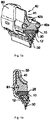
- FIG. 1a On the figure 1a is shown in perspective a wiper blade for windows of vehicles made according to the technology "flat blade"("FiatBlade”).
- the structure of this blade includes a longitudinal support 10 of extruded semi-rigid plastic material comprising a cavity intended to house a metal stiffening rod or “vertebra", of planar shape extending substantially over the entire length of the structure of the structure. wiper blade.
- the support 10 also comprises a longitudinal claw 12 into which is introduced an elastomer wiper blade 30.
- the accessory 40 As shown in figure 1a on the longitudinal support 10 is assembled and fixed an accessory 40 made by extrusion independently of the support 10.
- the accessory 40 comprises an aerodynamic deflector 41 which is combined a fluid distribution / projection device consisting of two side channels 42a, 42b for liquid transport holes drilled, not shown, to allow the projection of a liquid of washing, for example, on a window of the vehicle.
- the accessory 40 of the figure 1a consists of a single material, here an extruded elastomer, the liquid distribution / projection device being a lateral extension of the aerodynamic deflector 41.
- the accessory 40 located above the support 10, has flanks 43a, 43b of the accessory carrying the liquid transport channels 42a, 42b, said flanks enclosing the support 10.
- liquid distribution / projection device it is not necessary for the liquid distribution / projection device to be combined with an aerodynamic deflector 41, the invention being able to be perfectly implemented with an accessory 40 consisting of the only distribution / projection device. It must be remembered that the presence of a Aerodynamic deflector is justified for front window wipers, but is of little interest for the rear windows.
- lateral transport channel embodiments described herein all involve a two-channel distribution / projection device 42a, 42b of transport, it should be understood that this choice is in no way limiting, the teaching of invention being applicable to a distribution / projection device having only one lateral transport channel.
- the wiper blade shown comprises a tip 60 disposed at one end of the structure and having means for closing the channels 42a, 42b of transport.
- These sealing means are, in this example, crushing means constituted by a lateral groove 61 formed inside the tip 60.
- figure 1c shows said tip 60 in the introduction phase by sliding on the end of the structure.
- the lateral groove 61 is arranged so as to crush and thus close the channels 42a, 42b.
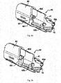
- FIG. 6a Another example of crush shutter is illustrated on the Figures 6a, 6b .
- the crushing means of the channels 42a, 42b of transport are constituted here by a crushing device 62 comprising a movable member 621 hingedly mounted on the tip 60 and an element fixed 622 retaining formed on the tip.
- a crushing device 62 comprising a movable member 621 hingedly mounted on the tip 60 and an element fixed 622 retaining formed on the tip.
- the mobile element 621 crushing is in the open position, the channel 42a is not closed.
- the movable element 621 is brought into the closed position of the figure 6b where the channel 42b is crushed at a suitable crush profile given to the movable member 621.
- the movable member 621 is held in the closed position by clipping on the fixed retainer 622.
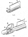
- FIG. figure 3 Another method of sealing the liquid transport channels is shown in FIG. figure 3 .
- This is a closure made by means of a stopper 63 disposed in the nozzle 60 and able to be inserted into a transport channel formed inside the profile of an aerodynamic deflector 41.
- the cap 63 is of cylindrical section and intended to cooperate with the channel 42 'of transport of the figure 2b .
- channel 42 of the figure 2a could be closed by a plug whose section would be conjugated with that of the canal.
- FIGS. Figures 5a, 5b is represented an end piece 60 'having, on the one hand, a plug 63' for a channel 42a of the distribution / projection device and, on the other hand, liquid supply means of said device constituted in this example by a cannula 64 connected to a second transport channel 42b.
- the functions of liquid supply and channel shutter are performed simultaneously by the tip 60 'disposed at one end of the wiping structure.
- At the other end of the structure can be disposed another tip 60 ", called transfer, such as that illustrated in FIGS. Figures 5a, 5b , comprising means for connecting the channel 42a to the channel 42b, these connection means being constituted by a tubular slot 65 formed in the tip 60 "transfer.
- dispensing device / liquid projection would be composed, at a first end of the wiping structure, of a first nozzle having means for closing the two channels 42a, 42b and at a second end, a second endpiece comprising two cannulas for supplying liquid to each transport channel 42a, 42b.
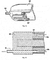
- the wiper blade may comprise a central connector disposed on the support 10 substantially in the middle of the structure, the liquid distribution / projection device consisting of two segments placed on the support 10 on the part and else of the central connector.
- This central connector is generally intended to connect the structure to the scanning mechanism of the wiper blade.
- a central connector 50 is shown on the figure 7 .
- the connector 50 comprises a rigid tube 51 adapted to be inserted into the transport channels of each segment.
- a rigid tube can, of course, be provided on each side of the connector 50 in the case where the distribution / projection device is constituted by two lateral transport channels.
- the connector 50 can be used to supply liquid to the distribution / projection device.
- the connector 50 has a central supply orifice 52 opening into the rigid tube 51.
- the wiper blade may then have, at one end, a closure cap of the transport channels and, at another end, a transfer tip. If a supply port is provided on each transport channel, then the broom may have at each end a closure cap of the channels.
Abstract
Balai d'essuyage pour une surface vitrée de véhicule, comprenant :- une structure destinée à recevoir une lame (30) d'essuyage, ladite structure comprenant un support longitudinal (10) comportant une cavité destinée à loger une tige métallique (20) de rigidification de forme plane s'étendant sensiblement sur toute la longueur de la structure du balai d'essuyage,- un accessoire (40) assemblé et fixé sur le support longitudinal (10), ledit accessoire (40) étant réalisé indépendamment du support longitudinal et comprenant un dispositif de distribution/projection de fluide constitué d'au moins un canal latéral (42a, 42b) de transport de liquide percés de trous, ledit accessoire (40) étant situé au-dessus du support longitudinal et comprenant des flancs (43a, 43b) portant le ou les canaux (42a, 42b) de transport de liquide et enserrant le support longitudinal (10), et- au moins un embout (60 ; 60') disposé à une extrémité de ladite structure et comportant des moyens (61 ; 63 ; 621,622) d'obturation dudit canal de transport.Wiper blade for a glazed surface of a vehicle, comprising: - a structure intended to receive a wiper blade (30), said structure comprising a longitudinal support (10) comprising a cavity intended to accommodate a metal rod (20) of rigidification of planar shape extending substantially over the entire length of the structure of the wiper blade, - an accessory (40) assembled and fixed on the longitudinal support (10), said accessory (40) being produced independently of the longitudinal support and comprising a fluid distribution / projection device consisting of at least one lateral channel (42a, 42b) for transporting liquid pierced with holes, said accessory (40) being located above the longitudinal support and comprising sides (43a, 43b) carrying the channel or channels (42a, 42b) for transporting liquid and enclosing the longitudinal support (10), and- at least one end piece (60; 60 ') disposed at one end of said structure and comprising means (61; 63; 621,622) for closing said transport channel.
Description
La présente invention concerne un balai d'essuyage pour vitres de véhicule.The present invention relates to a wiper blade for vehicle windows.
Elle concerne également un dispositif d'essuyage comprenant un balai d'essuyage tel que décrit dans la présente invention.It also relates to a wiper device comprising a wiper blade as described in the present invention.
Il existe aujourd'hui une technologie de balais d'essuyage pour vitres de véhicule connue sous le nom de « balai plat » (ou « Flat Blade » en anglo-saxon) et dont un exemple de réalisation est décrit dans la demande internationale n°
Cette technologie « balai plat » consiste en une structure construite autour d'une pièce longitudinale monobloc constituée de deux parties fonctionnellement distinctes.This "flat mop" technology consists of a structure built around a one-piece longitudinal part made up of two functionally distinct parts.
Une première partie est un support en matériau plastique semi-rigide comportant, d'une part, une cavité dans laquelle est logée une tige de rigidification généralement métallique, appelée également « vertèbre », et, d'autre part, une griffe portant la lame d'essuyage en élastomère.A first part is a support of semi-rigid plastic material comprising, on the one hand, a cavity in which is housed a generally metallic stiffening rod, also called "vertebra", and, on the other hand, a claw carrying the blade elastomer wiper.
Une deuxième partie de ladite pièce longitudinale monobloc est un accessoire destiné à améliorer l'efficacité et la qualité de l'essuyage. La demande internationale précitée montre comme exemple d'accessoire un dispositif de distribution/projection d'un liquide de lavage approprié qui permet, par action conjuguée avec le mouvement de balayage de la lame d'essuyage, d'éliminer certaines particules solides pouvant se fixer sur les vitres, comme les projections de boue ou les résidus d'insectes écrasés contre le pare-brise. Ledit dispositif de distribution/projection de liquide peut comporter un ou plusieurs canaux de transport de liquide munis de trous latéraux à travers lesquels le liquide de lavage est projeté contre les vitres du véhicule.A second portion of said longitudinal piece is an accessory accessory to improve the efficiency and quality of wiping. The aforementioned international application shows, as an example of an accessory, a device for dispensing / spraying a suitable washing liquid which makes it possible, by virtue of its combined action with the scanning movement of the wiping blade, to eliminate certain solid particles which can be fixed. on windows, such as mud splatter or insect residue crushed against the windshield. The liquid dispensing / splashing device may have one or more liquid transport channels provided with side holes through which the washing liquid is projected against the windows of the vehicle.
La demande internationale n°
On connaît également de la demande de brevet européen n°
Cependant, aucun des documents de l'état de la technique mentionnés ci-dessus ne décrit de moyens aptes à produire la projection de liquide recherchée à travers les ouvertures pratiquées le long du ou des canaux de transport.However, none of the documents of the state of the art mentioned above describes means capable of producing the desired liquid projection through the openings made along the transport channel or channels.
C'est pourquoi l'invention propose un balai d'essuyage pour vitres de véhicule, selon la revendication 1.This is why the invention proposes a wiper blade for vehicle windows, according to claim 1.
Ainsi, on comprend que les moyens d'obturation situés sur l'embout d'extrémité produisent une surpression du liquide contenu dans le canal de transport propre à forcer le passage du liquide à travers les trous latéraux du canal.Thus, it is understood that the closure means located on the end piece produce an overpressure of the liquid contained in the transport channel clean to force the passage of liquid through the side holes of the channel.
Ledit canal de transport peut être coextrudé avec le support longitudinal du balai ou constituer des pièces séparées fixées directement sur ledit support par divers moyens comme par clippage, assemblage en queue d'aronde, etc.Said transport channel may be coextruded with the longitudinal support of the blade or constitute separate parts fixed directly on said support by various means such as clipping, dovetail assembly, etc.
On peut aussi envisager, comme dans la demande de brevet européen n°
Selon une première alternative, ledit canal de transport est réalisé à l'intérieur d'un profilé constituant ledit déflecteur aérodynamique, avec l'avantage d'un encombrement minimum pour le dispositif de distribution/projection qui se trouve alors intégré dans la géométrie du déflecteur.According to a first alternative, said transport channel is formed inside a profile constituting said aerodynamic deflector, with the advantage of a minimum space requirement for the distribution / projection device which is then integrated into the geometry of the deflector .
Selon une deuxième alternative, ledit canal de transport constitue une extension dudit déflecteur aérodynamique, avec l'avantage de permettre une projection de liquide au plus près des vitres du véhicule.According to a second alternative, said transport channel constitutes an extension of said aerodynamic deflector, with the advantage of allowing a projection of liquid as close as possible to the windows of the vehicle.
Dans un premier mode de réalisation, lesdits moyens d'obturation sont constitués par un bouchon apte à être inséré à l'intérieur dudit canal de transport de liquide.In a first embodiment, said closure means are constituted by a plug adapted to be inserted inside said liquid transport channel.
Dans un deuxième mode de réalisation, lesdits moyens d'obturation sont constitués par des moyens d'écrasement dudit canal de transport de liquide.In a second embodiment, said sealing means are constituted by crushing means of said liquid transport channel.
Selon un premier mode de mise en oeuvre, lesdits moyens d'écrasement comprennent un élément d'écrasement mobile, apte à être amené d'une position ouverte à une position d'obturation, et des moyens de retenue aptes à immobiliser ledit élément d'écrasement en position d'obturation.According to a first embodiment, said crushing means comprise a movable crushing element, capable of being brought from an open position to a closed position, and retaining means able to immobilize said element. crushing in the closed position.
Selon un deuxième mode de mise en oeuvre, lesdits moyens d'écrasement sont constitués par une rainure latérale ménagée à l'intérieur dudit embout.According to a second mode of implementation, said crushing means are constituted by a lateral groove formed inside said tip.
Comme on le verra en détail plus loin, l'embout comportant lesdits moyens d'obturation peut être associé à un embout de transfert disposé à une seconde extrémité de la structure et comportant des moyens de raccordement dudit canal de transport à un second canal de transport. Dans cette réalisation, l'invention prévoit que ledit embout comporte en outre des moyens d'alimentation en liquide dudit dispositif de distribution/projection de liquide. On obtient alors un dispositif de distribution/projection de liquide à deux canaux de transport, comportant à une extrémité un embout de transfert raccordant les deux canaux entre eux, et à une autre extrémité un embout servant à la fois à obturer les canaux et les alimenter en liquide.As will be seen in detail below, the tip comprising said closure means may be associated with a transfer tip disposed at a second end of the structure and comprising means for connecting said transport channel to a second transport channel. . In this embodiment, the invention provides that said tip further comprises liquid supply means of said dispensing device / liquid projection. We then obtain a device distribution / projection of liquid with two transport channels, having at one end a transfer tip connecting the two channels together, and at another end a nozzle for both closing the channels and supplying liquid.
L'alimentation en liquide peut être également réalisée, selon l'invention, au moyen d'un orifice central d'alimentation en liquide d'au moins un canal de transport. Dans un exemple de réalisation, ledit orifice central d'alimentation est porté par un connecteur central, apte à relier le balai d'essuyage à un mécanisme d'entraînement.The liquid supply can also be performed, according to the invention, by means of a central liquid supply port of at least one transport channel. In an exemplary embodiment, said central supply port is carried by a central connector, adapted to connect the wiper blade to a drive mechanism.
La description qui va suivre en regard des dessins annexés, donnés à titre d'exemples non limitatifs, fera bien comprendre en quoi consiste l'invention et comment elle peut être réalisée.
- La
figure 1a est une vue en perspective d'un balai d'essuyage conforme à l'invention. - La
figure 1b est une vue en coupe partielle du balai de lafigure 1a . - La
figure 1c est une vue en perspective montrant l'assemblage du balai desfigures 1a et1 b. - La
figure 2a est une vue en perspective d'une première variante du dispositif de distribution/projection montré sur lesfigures 1a à 1c . - La
figure 2b est une vue en perspective d'une deuxième variante du dispositif de distribution/projection montré sur lesfigures 1a à 1c . - La
figure 3 est une vue en perspective montrant l'assemblage d'un balai d'essuyage comprenant le dispositif de distribution/projection montré sur lafigure 2a . - La
figure 4a est une vue en perspective d'un embout d'extrémité conforme à l'invention. - La
figure 4b est une vue de dessus en coupe de l'embout de lafigure 4a . - La
figure 5a est une vue en perspective d'un embout de transfert conforme à l'invention. - La
figure 5b est une vue de dessus en coupe de l'embout de transfert de lafigure 5a . - La
figure 6a est une vue en perspective d'un balai d'essuyage conforme à l'invention en position ouverte des moyens d'écrasement. - La
figure 6b est une vue en perspective du balai d'essuyage de lafigure 6a en position d'obturation des moyens d'écrasement. - La
figure 7 est une vue en perspective d'un connecteur central de raccordement d'un balai d'essuyage à deux segments d'accessoire.
- The
figure 1a is a perspective view of a wiper blade according to the invention. - The
figure 1b is a partial sectional view of the broom of thefigure 1a . - The
figure 1c is a perspective view showing the assembly of the broom offigures 1a and1 b. - The
figure 2a is a perspective view of a first variant of the distribution / projection device shown in FIGS.Figures 1a to 1c . - The
figure 2b is a perspective view of a second variant of the distribution / projection device shown in FIGS.Figures 1a to 1c . - The
figure 3 is a perspective view showing the assembly of a wiper blade comprising the dispensing / projection device shown in FIG.figure 2a . - The
figure 4a is a perspective view of an end cap according to the invention. - The
figure 4b is a sectional top view of the mouthpiece of thefigure 4a . - The
figure 5a is a perspective view of a transfer tip according to the invention. - The
figure 5b is a sectional top view of the transfer tip of thefigure 5a . - The
figure 6a is a perspective view of a wiper blade according to the invention in the open position of the crushing means. - The
figure 6b is a perspective view of the wiper blade of thefigure 6a in the closed position of the crushing means. - The
figure 7 is a perspective view of a central connector for connecting a wiper to two accessory segments.
Sur la
Comme le montre la
L'accessoire 40 de la
L'accessoire 40, situé au-dessus du support 10, présente des flancs 43a, 43b de l'accessoire, portant les canaux 42a, 42b de transport de liquide, lesdits flancs enserrant le support 10.The
Bien entendu, il n'est pas nécessaire que le dispositif de distribution/projection de liquide soit combiné à un déflecteur aérodynamique 41 , l'invention pouvant être parfaitement mise en oeuvre avec un accessoire 40 constitué du seul dispositif de distribution/projection. Il faut seulement rappeler que la présence d'un déflecteur aérodynamique se justifie pour des Balais d'essuyage de vitres avant, mais ne présente que peu d'intérêt pour les vitres arrière.Of course, it is not necessary for the liquid distribution / projection device to be combined with an
De même, si les modes de réalisation à canaux de transport latéraux décrits ici impliquent tous un dispositif de distribution/projection à deux canaux 42a, 42b de transport, il doit être compris que ce choix n'est nullement limitatif, l'enseignement de l'invention pouvant s'appliquer à un dispositif de distribution/projection ne comportant qu'un seul canal de transport latéral.Likewise, if the lateral transport channel embodiments described herein all involve a two-channel distribution /
Dans le cadre de la combinaison d'un dispositif de distribution/projection de liquide avec un déflecteur aérodynamique, il convient de mentionner les variantes des
Comme on peut le voir sur les
Un autre exemple d'obturation par écrasement est illustré sur les
Un autre mode d'obturation des canaux de transport de liquide est montré à la
Sur les
Une autre configuration possible de dispositif de distribution/projection de liquide, non représentée sur les figures, serait composée, à une première extrémité de la structure d'essuyage, d'un premier embout comportant des moyens d'obturation des deux canaux 42a, 42b et, à une deuxième extrémité, d'un deuxième embout comportant deux canules destinées à alimenter en liquide chaque canal 42a, 42b de transport.Another possible configuration of dispensing device / liquid projection, not shown in the figures, would be composed, at a first end of the wiping structure, of a first nozzle having means for closing the two
Selon un mode de réalisation particulier, le balai d'essuyage peut comporter un connecteur central disposé sur le support 10 sensiblement au milieu de la structure, le dispositif de distribution/projection de liquide étant constitué de deux segments placés sur le support 10 de part et d'autre du connecteur central. Ce connecteur central est, d'une manière générale, destiné à relier la structure au mécanisme d'entraînement en balayage du balai d'essuyage. Un tel connecteur central 50 est montré sur la
Le balai d'essuyage peut alors présenter, à une extrémité, un embout de bouchage des canaux de transport et, à une autre extrémité, un embout de transfert. Si un orifice d'alimentation est prévu sur chaque canal de transport, alors le balai peut comporter à chaque extrémité un embout de bouchage des canaux.The wiper blade may then have, at one end, a closure cap of the transport channels and, at another end, a transfer tip. If a supply port is provided on each transport channel, then the broom may have at each end a closure cap of the channels.
Claims (14)
Applications Claiming Priority (3)
| Application Number | Priority Date | Filing Date | Title |
|---|---|---|---|
| FR0706336A FR2920729B1 (en) | 2007-09-10 | 2007-09-10 | LIQUID SPRAYING WIPER BLADE FOR VEHICLE WINDOWS |
| EP08786710.7A EP2188160B1 (en) | 2007-09-10 | 2008-07-31 | Liquid-projecting wiper for vehicle windows |
| PCT/EP2008/060088 WO2009033885A1 (en) | 2007-09-10 | 2008-07-31 | Liquid-projecting wiper for vehicle windows |
Related Parent Applications (2)
| Application Number | Title | Priority Date | Filing Date |
|---|---|---|---|
| EP08786710.7A Division EP2188160B1 (en) | 2007-09-10 | 2008-07-31 | Liquid-projecting wiper for vehicle windows |
| EP08786710.7A Division-Into EP2188160B1 (en) | 2007-09-10 | 2008-07-31 | Liquid-projecting wiper for vehicle windows |
Publications (2)
| Publication Number | Publication Date |
|---|---|
| EP3498547A1 true EP3498547A1 (en) | 2019-06-19 |
| EP3498547B1 EP3498547B1 (en) | 2020-08-26 |
Family
ID=39181820
Family Applications (2)
| Application Number | Title | Priority Date | Filing Date |
|---|---|---|---|
| EP08786710.7A Active EP2188160B1 (en) | 2007-09-10 | 2008-07-31 | Liquid-projecting wiper for vehicle windows |
| EP19155168.8A Active EP3498547B1 (en) | 2007-09-10 | 2008-07-31 | Windscreen wiper with projection of liquid for windscreens of a vehicle |
Family Applications Before (1)
| Application Number | Title | Priority Date | Filing Date |
|---|---|---|---|
| EP08786710.7A Active EP2188160B1 (en) | 2007-09-10 | 2008-07-31 | Liquid-projecting wiper for vehicle windows |
Country Status (3)
| Country | Link |
|---|---|
| EP (2) | EP2188160B1 (en) |
| FR (1) | FR2920729B1 (en) |
| WO (1) | WO2009033885A1 (en) |
Cited By (1)
| Publication number | Priority date | Publication date | Assignee | Title |
|---|---|---|---|---|
| CN106394508A (en) * | 2015-07-29 | 2017-02-15 | 罗伯特·博世有限公司 | Wiper blade device |
Families Citing this family (26)
| Publication number | Priority date | Publication date | Assignee | Title |
|---|---|---|---|---|
| FR2923785B1 (en) * | 2007-11-19 | 2009-12-25 | Valeo Systemes Dessuyage | WIPER BLADE FOR VEHICLE WINDOWS. |
| FR2933930B1 (en) * | 2008-07-15 | 2010-12-17 | Valeo Systemes Dessuyage | HYDRAULIC CONNECTOR IN PARTICULAR FOR A WINDSCREEN WIPER SYSTEM OF A MOTOR VEHICLE |
| DE102009014313A1 (en) * | 2009-03-25 | 2010-09-30 | Valeo Systèmes d'Essuyage | wiper blade |
| ES2445657T3 (en) * | 2009-04-16 | 2014-03-04 | Federal-Mogul S.A. | Windshield wiper device |
| DE102009029432A1 (en) * | 2009-09-14 | 2011-03-24 | Robert Bosch Gmbh | Wiper blade in flat bar construction |
| FR2964618B1 (en) * | 2010-09-09 | 2012-10-12 | Valeo Systemes Dessuyage | DEVICE FOR SOLIDARIZING A LAMP ON A WIPING BROOM |
| DE102010056461A1 (en) * | 2010-12-30 | 2012-07-26 | Valeo Systèmes d'Essuyage | Wiper blade for cleaning windows of motor vehicles |
| FR2973314B1 (en) * | 2011-03-31 | 2013-10-04 | Valeo Systemes Dessuyage | END CAP WITH A DEVICE FOR HINGING A WIPING BLADE |
| FR2973312B1 (en) | 2011-03-31 | 2013-05-03 | Valeo Systemes Dessuyage | END TIP FOR TUMBLING BRUSH |
| FR2973313B1 (en) * | 2011-03-31 | 2013-05-03 | Valeo Systemes Dessuyage | PRIMARY PART AND SECONDARY PART OF A TIP END END CAP |
| FR2973758B1 (en) * | 2011-04-06 | 2013-05-17 | Valeo Systemes Dessuyage | ASSEMBLY OF A TIP AND A DEVICE FOR SPRAYING A LIQUID, WIPER BLADE COMPRISING SUCH AN ASSEMBLY, METHOD FOR MOUNTING A DEVICE FOR PROJECTING A LIQUID ON A TIP |
| FR2973759B1 (en) | 2011-04-06 | 2016-10-21 | Valeo Systemes Dessuyage | LIQUID SPREADING DEVICE FOR WIPING BROOM |
| DE102011050104A1 (en) * | 2011-05-04 | 2012-11-08 | Valeo Systèmes d'Essuyage | Wiper blade for window of motor vehicles, has wiper blade body which is fastened to wiper arm by wiper blade adapter in replaceable manner, where wiper blade adapter has nozzle for supplying washing liquid to washing liquid channel |
| FR2975061B1 (en) | 2011-05-09 | 2013-05-24 | Peugeot Citroen Automobiles Sa | WIPER BLADE WITH LIQUID PROJECTION DEVICE |
| FR2975060B1 (en) * | 2011-05-09 | 2013-05-24 | Peugeot Citroen Automobiles Sa | WIPER BLADE WITH A LIQUID PROJECTION DEVICE ON THE RACLETTE LIP |
| FR2975064B1 (en) * | 2011-05-13 | 2013-05-17 | Valeo Systemes Dessuyage | LIQUID SPREADING DEVICE FOR WIPING BROOM |
| FR2994144B1 (en) * | 2012-08-02 | 2014-08-29 | Valeo Systemes Dessuyage | CONNECTION DEVICE BETWEEN A WIPER ARM AND A WIPER, COMPRISING A OVERMOLD TUBE |
| FR2994147B1 (en) * | 2012-08-02 | 2016-08-05 | Valeo Systemes Dessuyage | DEVICE FOR CONNECTION BETWEEN A WIPER ARM AND A WIPER, COMPRISING A LIQUID CIRCULATION CIRCUIT |
| FR3007360B1 (en) * | 2013-06-20 | 2015-07-03 | Valeo Systemes Dessuyage | HEATING DEVICE FOR A WIPER BLADE AND ICE WIPER BLADE INCLUDING SUCH A HEATING DEVICE |
| FR3039482A1 (en) * | 2015-07-28 | 2017-02-03 | Valeo Systemes Dessuyage | AIR DEFLECTOR COMPRISING A WIPER BRUSH AND WIPING BRUSH COMPRISING SUCH AN AIR DEFLECTOR AND AT LEAST ONE END TIP. |
| FR3086617B1 (en) | 2018-09-28 | 2021-01-29 | Valeo Systemes Dessuyage | WINDSCREEN WIPER BLADE SPRAYING LIQUID FOR MOTOR VEHICLE WINDOWS, AND IMPROVING THE WATERPROOFING OF THIS BROOM |
| DE102018251713A1 (en) * | 2018-12-27 | 2020-07-02 | Robert Bosch Gmbh | Wiper blade device |
| FR3091682B1 (en) * | 2019-01-10 | 2020-12-18 | Valeo Systemes Dessuyage | END CAP FOR A MOTOR VEHICLE WIPER BRUSH |
| FR3122385B1 (en) * | 2021-04-29 | 2024-04-12 | Valeo Systemes Dessuyage | Wiping system. |
| DE102021213153A1 (en) * | 2021-11-23 | 2023-05-25 | Robert Bosch Gesellschaft mit beschränkter Haftung | Wiper blade, in particular for a motor vehicle |
| FR3138091A1 (en) * | 2022-07-22 | 2024-01-26 | Valeo Systèmes D’Essuyage | Windshield wiper blade and blade manufacturing processes |
Citations (6)
| Publication number | Priority date | Publication date | Assignee | Title |
|---|---|---|---|---|
| DE10000373A1 (en) * | 2000-01-07 | 2001-08-16 | Valeo Auto Electric Gmbh | Wiper blade for motor vehicle's windscreen wiper system has hood or cap type terminating piece at end and with cavity open to at least one side of terminating piece, and wiper strip by end is guided into cavity |
| EP1209050A2 (en) | 2000-11-24 | 2002-05-29 | Robert Bosch Gmbh | Wiper apparatus and method for producing a wiper apparatus |
| US6470527B1 (en) * | 2000-11-27 | 2002-10-29 | Ali Boncoglu | Environmentally friendly windshield wiper and cleaning assembly |
| DE10323998A1 (en) * | 2003-05-27 | 2004-12-23 | Valeo Systèmes d`Essuyage | Wiper blade for cleaning vehicle windscreen has wiper body and rubber wiper element as separate parts and at least one spray channel integrated into wiper body for transporting liquid |
| DE102004056835A1 (en) * | 2004-11-25 | 2006-06-01 | Valeo Systèmes d`Essuyage | wiper blade |
| WO2007000346A1 (en) | 2005-06-29 | 2007-01-04 | Valeo Systemes D'essuyage | Wiping device |
-
2007
- 2007-09-10 FR FR0706336A patent/FR2920729B1/en active Active
-
2008
- 2008-07-31 EP EP08786710.7A patent/EP2188160B1/en active Active
- 2008-07-31 EP EP19155168.8A patent/EP3498547B1/en active Active
- 2008-07-31 WO PCT/EP2008/060088 patent/WO2009033885A1/en active Application Filing
Patent Citations (6)
| Publication number | Priority date | Publication date | Assignee | Title |
|---|---|---|---|---|
| DE10000373A1 (en) * | 2000-01-07 | 2001-08-16 | Valeo Auto Electric Gmbh | Wiper blade for motor vehicle's windscreen wiper system has hood or cap type terminating piece at end and with cavity open to at least one side of terminating piece, and wiper strip by end is guided into cavity |
| EP1209050A2 (en) | 2000-11-24 | 2002-05-29 | Robert Bosch Gmbh | Wiper apparatus and method for producing a wiper apparatus |
| US6470527B1 (en) * | 2000-11-27 | 2002-10-29 | Ali Boncoglu | Environmentally friendly windshield wiper and cleaning assembly |
| DE10323998A1 (en) * | 2003-05-27 | 2004-12-23 | Valeo Systèmes d`Essuyage | Wiper blade for cleaning vehicle windscreen has wiper body and rubber wiper element as separate parts and at least one spray channel integrated into wiper body for transporting liquid |
| DE102004056835A1 (en) * | 2004-11-25 | 2006-06-01 | Valeo Systèmes d`Essuyage | wiper blade |
| WO2007000346A1 (en) | 2005-06-29 | 2007-01-04 | Valeo Systemes D'essuyage | Wiping device |
Cited By (2)
| Publication number | Priority date | Publication date | Assignee | Title |
|---|---|---|---|---|
| CN106394508A (en) * | 2015-07-29 | 2017-02-15 | 罗伯特·博世有限公司 | Wiper blade device |
| CN106394508B (en) * | 2015-07-29 | 2021-06-25 | 罗伯特·博世有限公司 | Wiper blade device |
Also Published As
| Publication number | Publication date |
|---|---|
| EP3498547B1 (en) | 2020-08-26 |
| FR2920729A1 (en) | 2009-03-13 |
| WO2009033885A1 (en) | 2009-03-19 |
| FR2920729B1 (en) | 2010-02-12 |
| EP2188160A1 (en) | 2010-05-26 |
| EP2188160B1 (en) | 2019-03-13 |
Similar Documents
| Publication | Publication Date | Title |
|---|---|---|
| EP2188160B1 (en) | Liquid-projecting wiper for vehicle windows | |
| EP2214938B1 (en) | Wiper arm for vehicle windows | |
| EP2861471B1 (en) | Wiper blade including a device and a means for spraying a washing liquid | |
| EP2691272B1 (en) | End piece having a device for securing a wiper blade | |
| EP2709880B1 (en) | A liquid-spraying device for a wiper blade | |
| FR2973758A1 (en) | ASSEMBLY OF A TIP AND A DEVICE FOR SPRAYING A LIQUID, WIPER BLADE COMPRISING SUCH AN ASSEMBLY, METHOD FOR MOUNTING A DEVICE FOR PROJECTING A LIQUID ON A TIP | |
| WO2014020282A1 (en) | Device for connecting a wiper arm and a wiper blade together including an area arranged to receive a plurality of spray openings | |
| EP2861472B1 (en) | Wiper blade having a hydraulic connector | |
| EP2349871B1 (en) | Device and assembly for supporting a pair of windscreen wipers, and corresponding packaging and method for mounting same | |
| EP3251903B1 (en) | End tip of a wiper blade and corresponding wiper assembly | |
| FR2929904A1 (en) | Cleaning liquid spraying device for e.g. flat wiper blade, of motor vehicle, has transporting ramps equipped with outlet orifices, where orifices spray cleaning liquid under liquid pressure higher than pressure applied for opening orifices | |
| FR2995850A1 (en) | WINDOW CLEANING SYSTEM OF A GLASS, IN PARTICULAR REAR WINDOW OF A MOTOR VEHICLE | |
| EP2965958B1 (en) | Assembly comprising a mechanical connector and a cannula for a vehicle windscreen-wiper blade | |
| EP3018017B1 (en) | Wiper blade for motor vehicle windscreens | |
| FR2975063A1 (en) | GLAZED SURFACE WIPING DEVICE OF A MOTOR VEHICLE | |
| WO2020064445A1 (en) | Liquid spraying wiper frame for motor vehicle windows, and optimisation of the sealing of this frame | |
| EP2707258B1 (en) | Liquid spraying device for a wiper blade | |
| EP3081442B1 (en) | Wiper blade and wiper assembly comprising such a blade | |
| EP3012163B1 (en) | Device for spraying windscreen washer liquid for a wiper of a vehicle windscreen wiping system | |
| FR3067312A1 (en) | ICE WIPER BLADE COMPRISING A SERIOUS MARKING, AND SERIOUS AERODYNAMIC DEFLECTOR FOR A WIPER BLADE | |
| FR3004685A1 (en) | ICE WIPER DEVICE | |
| EP3081441B1 (en) | Wiper blade and wiper assembly comprising such a blade | |
| WO2022175417A1 (en) | Device for connecting a wiper blade to an arm of a wiping system | |
| EP3615390B1 (en) | End piece for a wiper blade | |
| FR2907738A1 (en) | Windscreen wiper blade connection device for motor vehicle, has trunnion introduced after connector is arranged in adapter, and co-operating with adapter and connector, and arm's distal end arranged inside adapter transversal to axis of arm |
Legal Events
| Date | Code | Title | Description |
|---|---|---|---|
| PUAI | Public reference made under article 153(3) epc to a published international application that has entered the european phase |
Free format text: ORIGINAL CODE: 0009012 |
|
| STAA | Information on the status of an ep patent application or granted ep patent |
Free format text: STATUS: REQUEST FOR EXAMINATION WAS MADE |
|
| 17P | Request for examination filed |
Effective date: 20190201 |
|
| AC | Divisional application: reference to earlier application |
Ref document number: 2188160 Country of ref document: EP Kind code of ref document: P |
|
| AK | Designated contracting states |
Kind code of ref document: A1 Designated state(s): AT BE BG CH CY CZ DE DK EE ES FI FR GB GR HR HU IE IS IT LI LT LU LV MC MT NL NO PL PT RO SE SI SK TR |
|
| GRAP | Despatch of communication of intention to grant a patent |
Free format text: ORIGINAL CODE: EPIDOSNIGR1 |
|
| STAA | Information on the status of an ep patent application or granted ep patent |
Free format text: STATUS: GRANT OF PATENT IS INTENDED |
|
| INTG | Intention to grant announced |
Effective date: 20200408 |
|
| GRAS | Grant fee paid |
Free format text: ORIGINAL CODE: EPIDOSNIGR3 |
|
| GRAA | (expected) grant |
Free format text: ORIGINAL CODE: 0009210 |
|
| STAA | Information on the status of an ep patent application or granted ep patent |
Free format text: STATUS: THE PATENT HAS BEEN GRANTED |
|
| AC | Divisional application: reference to earlier application |
Ref document number: 2188160 Country of ref document: EP Kind code of ref document: P |
|
| AK | Designated contracting states |
Kind code of ref document: B1 Designated state(s): AT BE BG CH CY CZ DE DK EE ES FI FR GB GR HR HU IE IS IT LI LT LU LV MC MT NL NO PL PT RO SE SI SK TR |
|
| REG | Reference to a national code |
Ref country code: GB Ref legal event code: FG4D Free format text: NOT ENGLISH |
|
| REG | Reference to a national code |
Ref country code: CH Ref legal event code: EP |
|
| REG | Reference to a national code |
Ref country code: DE Ref legal event code: R096 Ref document number: 602008063197 Country of ref document: DE |
|
| REG | Reference to a national code |
Ref country code: AT Ref legal event code: REF Ref document number: 1306083 Country of ref document: AT Kind code of ref document: T Effective date: 20200915 |
|
| REG | Reference to a national code |
Ref country code: IE Ref legal event code: FG4D Free format text: LANGUAGE OF EP DOCUMENT: FRENCH |
|
| REG | Reference to a national code |
Ref country code: LT Ref legal event code: MG4D |
|
| PG25 | Lapsed in a contracting state [announced via postgrant information from national office to epo] |
Ref country code: BG Free format text: LAPSE BECAUSE OF FAILURE TO SUBMIT A TRANSLATION OF THE DESCRIPTION OR TO PAY THE FEE WITHIN THE PRESCRIBED TIME-LIMIT Effective date: 20201126 Ref country code: HR Free format text: LAPSE BECAUSE OF FAILURE TO SUBMIT A TRANSLATION OF THE DESCRIPTION OR TO PAY THE FEE WITHIN THE PRESCRIBED TIME-LIMIT Effective date: 20200826 Ref country code: LT Free format text: LAPSE BECAUSE OF FAILURE TO SUBMIT A TRANSLATION OF THE DESCRIPTION OR TO PAY THE FEE WITHIN THE PRESCRIBED TIME-LIMIT Effective date: 20200826 Ref country code: GR Free format text: LAPSE BECAUSE OF FAILURE TO SUBMIT A TRANSLATION OF THE DESCRIPTION OR TO PAY THE FEE WITHIN THE PRESCRIBED TIME-LIMIT Effective date: 20201127 Ref country code: NO Free format text: LAPSE BECAUSE OF FAILURE TO SUBMIT A TRANSLATION OF THE DESCRIPTION OR TO PAY THE FEE WITHIN THE PRESCRIBED TIME-LIMIT Effective date: 20201126 Ref country code: PT Free format text: LAPSE BECAUSE OF FAILURE TO SUBMIT A TRANSLATION OF THE DESCRIPTION OR TO PAY THE FEE WITHIN THE PRESCRIBED TIME-LIMIT Effective date: 20201228 Ref country code: FI Free format text: LAPSE BECAUSE OF FAILURE TO SUBMIT A TRANSLATION OF THE DESCRIPTION OR TO PAY THE FEE WITHIN THE PRESCRIBED TIME-LIMIT Effective date: 20200826 Ref country code: SE Free format text: LAPSE BECAUSE OF FAILURE TO SUBMIT A TRANSLATION OF THE DESCRIPTION OR TO PAY THE FEE WITHIN THE PRESCRIBED TIME-LIMIT Effective date: 20200826 |
|
| REG | Reference to a national code |
Ref country code: NL Ref legal event code: MP Effective date: 20200826 |
|
| REG | Reference to a national code |
Ref country code: AT Ref legal event code: MK05 Ref document number: 1306083 Country of ref document: AT Kind code of ref document: T Effective date: 20200826 |
|
| PG25 | Lapsed in a contracting state [announced via postgrant information from national office to epo] |
Ref country code: LV Free format text: LAPSE BECAUSE OF FAILURE TO SUBMIT A TRANSLATION OF THE DESCRIPTION OR TO PAY THE FEE WITHIN THE PRESCRIBED TIME-LIMIT Effective date: 20200826 Ref country code: PL Free format text: LAPSE BECAUSE OF FAILURE TO SUBMIT A TRANSLATION OF THE DESCRIPTION OR TO PAY THE FEE WITHIN THE PRESCRIBED TIME-LIMIT Effective date: 20200826 Ref country code: NL Free format text: LAPSE BECAUSE OF FAILURE TO SUBMIT A TRANSLATION OF THE DESCRIPTION OR TO PAY THE FEE WITHIN THE PRESCRIBED TIME-LIMIT Effective date: 20200826 Ref country code: IS Free format text: LAPSE BECAUSE OF FAILURE TO SUBMIT A TRANSLATION OF THE DESCRIPTION OR TO PAY THE FEE WITHIN THE PRESCRIBED TIME-LIMIT Effective date: 20201226 |
|
| PG25 | Lapsed in a contracting state [announced via postgrant information from national office to epo] |
Ref country code: EE Free format text: LAPSE BECAUSE OF FAILURE TO SUBMIT A TRANSLATION OF THE DESCRIPTION OR TO PAY THE FEE WITHIN THE PRESCRIBED TIME-LIMIT Effective date: 20200826 Ref country code: CZ Free format text: LAPSE BECAUSE OF FAILURE TO SUBMIT A TRANSLATION OF THE DESCRIPTION OR TO PAY THE FEE WITHIN THE PRESCRIBED TIME-LIMIT Effective date: 20200826 Ref country code: DK Free format text: LAPSE BECAUSE OF FAILURE TO SUBMIT A TRANSLATION OF THE DESCRIPTION OR TO PAY THE FEE WITHIN THE PRESCRIBED TIME-LIMIT Effective date: 20200826 Ref country code: RO Free format text: LAPSE BECAUSE OF FAILURE TO SUBMIT A TRANSLATION OF THE DESCRIPTION OR TO PAY THE FEE WITHIN THE PRESCRIBED TIME-LIMIT Effective date: 20200826 |
|
| REG | Reference to a national code |
Ref country code: DE Ref legal event code: R097 Ref document number: 602008063197 Country of ref document: DE |
|
| PG25 | Lapsed in a contracting state [announced via postgrant information from national office to epo] |
Ref country code: ES Free format text: LAPSE BECAUSE OF FAILURE TO SUBMIT A TRANSLATION OF THE DESCRIPTION OR TO PAY THE FEE WITHIN THE PRESCRIBED TIME-LIMIT Effective date: 20200826 Ref country code: AT Free format text: LAPSE BECAUSE OF FAILURE TO SUBMIT A TRANSLATION OF THE DESCRIPTION OR TO PAY THE FEE WITHIN THE PRESCRIBED TIME-LIMIT Effective date: 20200826 |
|
| PG25 | Lapsed in a contracting state [announced via postgrant information from national office to epo] |
Ref country code: SK Free format text: LAPSE BECAUSE OF FAILURE TO SUBMIT A TRANSLATION OF THE DESCRIPTION OR TO PAY THE FEE WITHIN THE PRESCRIBED TIME-LIMIT Effective date: 20200826 |
|
| PLBE | No opposition filed within time limit |
Free format text: ORIGINAL CODE: 0009261 |
|
| STAA | Information on the status of an ep patent application or granted ep patent |
Free format text: STATUS: NO OPPOSITION FILED WITHIN TIME LIMIT |
|
| PG25 | Lapsed in a contracting state [announced via postgrant information from national office to epo] |
Ref country code: IT Free format text: LAPSE BECAUSE OF FAILURE TO SUBMIT A TRANSLATION OF THE DESCRIPTION OR TO PAY THE FEE WITHIN THE PRESCRIBED TIME-LIMIT Effective date: 20200826 |
|
| 26N | No opposition filed |
Effective date: 20210527 |
|
| PG25 | Lapsed in a contracting state [announced via postgrant information from national office to epo] |
Ref country code: SI Free format text: LAPSE BECAUSE OF FAILURE TO SUBMIT A TRANSLATION OF THE DESCRIPTION OR TO PAY THE FEE WITHIN THE PRESCRIBED TIME-LIMIT Effective date: 20200826 |
|
| REG | Reference to a national code |
Ref country code: CH Ref legal event code: PL |
|
| GBPC | Gb: european patent ceased through non-payment of renewal fee |
Effective date: 20210731 |
|
| PG25 | Lapsed in a contracting state [announced via postgrant information from national office to epo] |
Ref country code: MC Free format text: LAPSE BECAUSE OF FAILURE TO SUBMIT A TRANSLATION OF THE DESCRIPTION OR TO PAY THE FEE WITHIN THE PRESCRIBED TIME-LIMIT Effective date: 20200826 |
|
| PG25 | Lapsed in a contracting state [announced via postgrant information from national office to epo] |
Ref country code: LI Free format text: LAPSE BECAUSE OF NON-PAYMENT OF DUE FEES Effective date: 20210731 Ref country code: GB Free format text: LAPSE BECAUSE OF NON-PAYMENT OF DUE FEES Effective date: 20210731 Ref country code: CH Free format text: LAPSE BECAUSE OF NON-PAYMENT OF DUE FEES Effective date: 20210731 |
|
| PG25 | Lapsed in a contracting state [announced via postgrant information from national office to epo] |
Ref country code: LU Free format text: LAPSE BECAUSE OF NON-PAYMENT OF DUE FEES Effective date: 20210731 |
|
| PG25 | Lapsed in a contracting state [announced via postgrant information from national office to epo] |
Ref country code: IE Free format text: LAPSE BECAUSE OF NON-PAYMENT OF DUE FEES Effective date: 20210731 |
|
| PG25 | Lapsed in a contracting state [announced via postgrant information from national office to epo] |
Ref country code: CY Free format text: LAPSE BECAUSE OF FAILURE TO SUBMIT A TRANSLATION OF THE DESCRIPTION OR TO PAY THE FEE WITHIN THE PRESCRIBED TIME-LIMIT Effective date: 20200826 |
|
| P01 | Opt-out of the competence of the unified patent court (upc) registered |
Effective date: 20230528 |
|
| PG25 | Lapsed in a contracting state [announced via postgrant information from national office to epo] |
Ref country code: HU Free format text: LAPSE BECAUSE OF FAILURE TO SUBMIT A TRANSLATION OF THE DESCRIPTION OR TO PAY THE FEE WITHIN THE PRESCRIBED TIME-LIMIT; INVALID AB INITIO Effective date: 20080731 |
|
| PGFP | Annual fee paid to national office [announced via postgrant information from national office to epo] |
Ref country code: FR Payment date: 20230727 Year of fee payment: 16 Ref country code: DE Payment date: 20230712 Year of fee payment: 16 Ref country code: BE Payment date: 20230721 Year of fee payment: 16 |