EP3498543A1 - Aircraft restraint systems with fixed default mode - Google Patents
Aircraft restraint systems with fixed default mode Download PDFInfo
- Publication number
- EP3498543A1 EP3498543A1 EP18207393.2A EP18207393A EP3498543A1 EP 3498543 A1 EP3498543 A1 EP 3498543A1 EP 18207393 A EP18207393 A EP 18207393A EP 3498543 A1 EP3498543 A1 EP 3498543A1
- Authority
- EP
- European Patent Office
- Prior art keywords
- strap
- feeder unit
- mode
- occupant
- restraint system
- Prior art date
- Legal status (The legal status is an assumption and is not a legal conclusion. Google has not performed a legal analysis and makes no representation as to the accuracy of the status listed.)
- Granted
Links
- 230000004044 response Effects 0.000 claims abstract description 31
- 230000033001 locomotion Effects 0.000 claims abstract description 17
- 230000001965 increasing effect Effects 0.000 claims abstract description 8
- 238000004891 communication Methods 0.000 claims description 11
- 230000000007 visual effect Effects 0.000 claims description 2
- 230000001133 acceleration Effects 0.000 description 13
- 238000012986 modification Methods 0.000 description 5
- 230000004048 modification Effects 0.000 description 5
- 206010019196 Head injury Diseases 0.000 description 2
- 230000000712 assembly Effects 0.000 description 2
- 238000000429 assembly Methods 0.000 description 2
- 230000008901 benefit Effects 0.000 description 2
- 230000008933 bodily movement Effects 0.000 description 2
- 238000011161 development Methods 0.000 description 2
- 230000002708 enhancing effect Effects 0.000 description 2
- 230000007246 mechanism Effects 0.000 description 2
- 230000002441 reversible effect Effects 0.000 description 2
- 208000027418 Wounds and injury Diseases 0.000 description 1
- 230000001413 cellular effect Effects 0.000 description 1
- 230000008859 change Effects 0.000 description 1
- 230000008878 coupling Effects 0.000 description 1
- 238000010168 coupling process Methods 0.000 description 1
- 238000005859 coupling reaction Methods 0.000 description 1
- 230000006378 damage Effects 0.000 description 1
- 230000003111 delayed effect Effects 0.000 description 1
- 238000013461 design Methods 0.000 description 1
- 230000004886 head movement Effects 0.000 description 1
- 230000000266 injurious effect Effects 0.000 description 1
- 208000014674 injury Diseases 0.000 description 1
- 238000009434 installation Methods 0.000 description 1
- 238000000034 method Methods 0.000 description 1
- 230000036316 preload Effects 0.000 description 1
- 230000035484 reaction time Effects 0.000 description 1
- 238000009877 rendering Methods 0.000 description 1
- 238000006467 substitution reaction Methods 0.000 description 1
Images


Classifications
-
- B—PERFORMING OPERATIONS; TRANSPORTING
- B64—AIRCRAFT; AVIATION; COSMONAUTICS
- B64D—EQUIPMENT FOR FITTING IN OR TO AIRCRAFT; FLIGHT SUITS; PARACHUTES; ARRANGEMENTS OR MOUNTING OF POWER PLANTS OR PROPULSION TRANSMISSIONS IN AIRCRAFT
- B64D11/00—Passenger or crew accommodation; Flight-deck installations not otherwise provided for
- B64D11/06—Arrangements of seats, or adaptations or details specially adapted for aircraft seats
- B64D11/062—Belts or other passenger restraint means for passenger seats
-
- B—PERFORMING OPERATIONS; TRANSPORTING
- B60—VEHICLES IN GENERAL
- B60R—VEHICLES, VEHICLE FITTINGS, OR VEHICLE PARTS, NOT OTHERWISE PROVIDED FOR
- B60R22/00—Safety belts or body harnesses in vehicles
- B60R22/34—Belt retractors, e.g. reels
- B60R22/343—Belt retractors, e.g. reels with electrically actuated locking means
-
- B—PERFORMING OPERATIONS; TRANSPORTING
- B60—VEHICLES IN GENERAL
- B60R—VEHICLES, VEHICLE FITTINGS, OR VEHICLE PARTS, NOT OTHERWISE PROVIDED FOR
- B60R22/00—Safety belts or body harnesses in vehicles
- B60R22/34—Belt retractors, e.g. reels
- B60R22/347—Belt retractors, e.g. reels with means for permanently locking the retractor during the wearing of the belt
-
- B—PERFORMING OPERATIONS; TRANSPORTING
- B60—VEHICLES IN GENERAL
- B60R—VEHICLES, VEHICLE FITTINGS, OR VEHICLE PARTS, NOT OTHERWISE PROVIDED FOR
- B60R22/00—Safety belts or body harnesses in vehicles
- B60R22/34—Belt retractors, e.g. reels
- B60R22/36—Belt retractors, e.g. reels self-locking in an emergency
- B60R22/415—Belt retractors, e.g. reels self-locking in an emergency with additional means allowing a permanent locking of the retractor during the wearing of the belt
-
- B—PERFORMING OPERATIONS; TRANSPORTING
- B60—VEHICLES IN GENERAL
- B60R—VEHICLES, VEHICLE FITTINGS, OR VEHICLE PARTS, NOT OTHERWISE PROVIDED FOR
- B60R22/00—Safety belts or body harnesses in vehicles
- B60R22/34—Belt retractors, e.g. reels
- B60R22/44—Belt retractors, e.g. reels with means for reducing belt tension during use under normal conditions
- B60R2022/442—Belt retractors, e.g. reels with means for reducing belt tension during use under normal conditions using one spring and one additional retraction device in parallel
- B60R2022/4426—Belt retractors, e.g. reels with means for reducing belt tension during use under normal conditions using one spring and one additional retraction device in parallel the additional retraction device being a second spring
- B60R2022/4433—Belt retractors, e.g. reels with means for reducing belt tension during use under normal conditions using one spring and one additional retraction device in parallel the additional retraction device being a second spring externally controlled
Definitions
- the present disclosure relates, in general, to aircraft restraint systems and, in particular, to modal aircraft restraint systems having two or more modes of operation including a fixed mode and an unfixed mode, of which the former is the default mode of operation.
- HIC head injury criteria
- the head movements of an aircraft occupant in an HIC event should result in a minimal or below-threshold head injury.
- aircraft certification in the United States requires engineers to demonstrate that a head strike into any one of several cabin furnishings complies with the HIC requirements specified in 14 C.F.R ⁇ 23.562 and 14 C.F.R ⁇ 25.562.
- HIC requirements may be satisfied in several ways, such as by providing head clearance and/or soft impact surfaces around the aircraft occupant. Both of these solutions, however, add cost and weight to the aircraft.
- Aircraft must include restraint systems to enhance occupant safety.
- some aircraft include fixed seatbelts, which have a strap that does not extend in response to the bodily movement of the occupant. While fixed seatbelts may provide a short HIC trajectory, allowing for smaller seat pitch installation, fixed seatbelts are uncomfortable and may severely limit the mobility of the occupant, including hampering the pilot's ability to reach controls and look through windows.
- Other aircraft include inertia reel seatbelts, which have a strap that is extendable or retractable except when occupant movement reaches a threshold that causes the inertia reel to lock, preventing further extension of the strap.
- Inertia reel seatbelts have a delayed reaction time for locking the occupant into a secured position, resulting in increased head motion than that allowed by a fixed seatbelt. Accordingly, a need has arisen for a modal restraint system that provides a similar or superior range of head motion as compared to a fixed seatbelt, while also increasing occupant comfort and mobility.
- the present disclosure is directed to a modal restraint system for an occupant of a seat of an aircraft.
- the modal restraint system includes a strap feeder unit and a strap selectively retractable into and extendable from the strap feeder unit.
- the strap is positionable adjacent to the occupant so as to dispose the occupant between the strap and the seat.
- the strap feeder unit is adapted to switch between a plurality of modes including a fixed mode and an unfixed mode.
- the strap is substantially unextendable from the strap feeder unit in the fixed mode.
- the strap is extendable from and retractable into the strap feeder unit in the unfixed mode.
- the strap feeder unit is in the fixed mode by default.
- the strap feeder unit is operable to switch to the unfixed mode in response to a user input, thereby increasing freedom of movement of the occupant relative to the seat of the aircraft.
- the strap feeder unit may include a spool operable to rotate in first and second directions to wind and unwind the strap thereabout, respectively.
- the strap feeder unit may include a locking module, the locking module engaging with the spool when the strap feeder unit is in the fixed mode to impede the spool from rotating in the second direction such that the strap is substantially unextendable.
- the plurality of modes may include a retracted fixed mode and the strap feeder unit may include a retraction module adapted to rotate the spool in the first direction to retract the strap into the strap feeder unit in the retracted fixed mode, thereby tightening the strap against the occupant.
- the unfixed mode may include an inertia reel mode and the strap feeder unit may include an inertia reel subassembly selectively engagable with the spool in the inertia reel mode.
- the strap may include a torso strap positionable adjacent to the torso of the occupant.
- the strap may include a lap strap positionable adjacent to the lap region of the occupant.
- the strap feeder unit may be further operable to switch to one of the fixed default mode or the retracted fixed mode in response to a cessation of the user input. In some embodiments, the strap feeder unit may be further operable to switch to one of the fixed default mode or the retracted fixed mode in response to a cessation of a predetermined time period. In certain embodiments, the strap feeder unit may be further operable to revert to the retracted fixed mode in response to a precautionary event. In some embodiments, the precautionary event may anticipate a life-threatening acceleration event. In certain embodiments, the life-threatening acceleration event may include a hard landing, a collision, an uncontrolled descent or turbulence. In some embodiments, reverting the strap feeder unit to the retracted fixed mode in response to the precautionary event may reduce the freedom of movement of the occupant during the life-threatening acceleration event.
- the modal restraint system may include a release selector in communication with the strap feeder unit, and the user input may include selection of the release selector by the occupant.
- the release selector may be switchable between a release position and an unrelease position, and the user input may include switching the release selector from the unrelease position to the release position.
- the release selector may include a button, the user input may include pressing of the button by the occupant and the strap feeder unit may be further operable to switch to the fixed mode in response to release of the button by the occupant.
- the release selector may include an input device such as a button, a lever, a knob or a pull cord.
- the release selector may be proximate to the seat.
- the release selector may be disabled in response to a precautionary event, thereby preventing the strap feeder unit from switching to the unfixed mode.
- the present disclosure is directed to an aircraft including a fuselage, a plurality of seats in the fuselage and a modal restraint system including a plurality of seatbelt subsystems.
- Each seatbelt subsystem is adapted to secure an occupant to one of the seats.
- Each seatbelt subsystem includes a strap feeder unit and a strap selectively retractable into and extendable from the strap feeder unit.
- the strap is positionable adjacent to the occupant so as to dispose the occupant between the strap and the seat.
- the strap feeder unit is adapted to switch between a plurality of modes including a fixed mode and an unfixed mode.
- the strap is substantially unextendable from the strap feeder unit in the fixed mode.
- the strap is extendable from and retractable into the strap feeder unit in the unfixed mode.
- the strap feeder unit is in the fixed mode by default.
- the strap feeder unit is operable to switch to the unfixed mode in response to a user input, thereby increasing freedom of movement of the occupant relative to the seat.
- the seatbelt subsystems may be located in the cockpit or passenger cabin of the aircraft.
- the unfixed mode may include an inertia reel mode.
- the modal restraint system may include a master release selector in communication with each of the seatbelt subsystems, the user input may include selection of the master release selector and the selection of the master release selector may cause or allow the strap feeder units of each of the seatbelt subsystems to switch to the unfixed mode.
- the master release selector may be located in the cockpit and selectable by a pilot.
- the plurality of modes may include a retracted fixed mode and the strap feeder unit may be adapted to retract the strap into the strap feeder unit in the retracted fixed mode, thereby tightening the strap against the occupant.
- the strap feeder units of each of the seatbelt subsystems may be operable to switch to the retracted fixed mode in response to a precautionary event.
- the aircraft may include a release selector in communication with the strap feeder unit, as well as a plurality of flight operation modes including a visual flight rules operation mode and an instrument flight rules operation mode. In such embodiments, the release selector may be disabled in response to switching to the instrument flight rules operation mode. In some embodiments, switching to the unfixed mode may increase the freedom of forward movement of the occupant relative to the seat.
- the devices, members, apparatuses, and the like described herein may be positioned in any desired orientation.
- the use of terms such as “above,” “below,” “upper,” “lower” or other like terms to describe a spatial relationship between various components or to describe the spatial orientation of aspects of such components should be understood to describe a relative relationship between the components or a spatial orientation of aspects of such components, respectively, as the devices described herein may be oriented in any desired direction.
- the term “coupled” may include direct or indirect coupling by any means, including by mere contact or by moving and/or non-moving mechanical connections.
- Rotorcraft 10 is a helicopter having a main rotor 12, which includes a plurality of rotor blade assemblies 14.
- Main rotor 12 is rotatable relative to a fuselage 16, which includes a cockpit 18 and a passenger cabin 20.
- Cockpit 18 and passenger cabin 20 include seats 22, 24, respectively, intended for occupants 26, such as pilots, crewmembers, passengers and the like.
- the pitch of rotor blade assemblies 14 can be collectively and/or cyclically manipulated to selectively control direction, thrust and lift of rotorcraft 10.
- a landing gear system 28 provides ground support for rotorcraft 10.
- a tailboom 30 extends from fuselage 16.
- a tail section 32 includes a tail rotor 34 that is rotatably coupled to the aft portion of tailboom 30. Tail rotor 34 controls the yaw of rotorcraft 10.
- Rotorcraft 10 includes a modal restraint system 36, which includes seatbelt, or restraint, subsystems 38a-38e.
- Seatbelt subsystems 38a, 38b are located in cockpit 18 and seatbelt subsystems 38c-38e are located in passenger cabin 20.
- Each seatbelt subsystem 38a-38e is adapted to secure one of occupants 26 to a respective seat 22, 24.
- Each seatbelt subsystem 38a-38e includes a strap 40 that is selectively retractable into and extendable from a strap feeder unit 42.
- Seatbelt subsystems 38a-38e may be switched between a plurality of modes including a fixed mode and an unfixed mode. In fixed mode, strap 40 is substantially unextendable from strap feeder unit 42.
- the modes of seatbelt subsystems 38a-38e may include a retracted fixed mode in which strap 40 is retracted into strap feeder unit 42 to tighten strap 40 against occupants 26.
- the modes of seatbelt subsystems 38a-38e may include an inertia reel mode, a type of unfixed mode, in which strap 40 is retractable into and extendable from strap feeder unit 42 unless strap 40 is pulled with a force sufficient to prevent strap feeder unit 42 from extending strap 40 any further, as may occur if the body of an occupant moves relative to rotorcraft 10 or seats 22, 24 with sufficient force.
- seatbelt subsystems 38a-38e are in fixed mode by default, or during normal operation of rotorcraft 10 in the absence of user, computer or other input to specify the mode of seatbelt subsystems 38a-38e.
- seatbelt subsystems 38a-38e may switch to unfixed mode in response to user input, which increases the freedom of bodily movement of occupants 26 relative to their respective seats 22, 24, thereby enhancing the comfort and mobility of each occupant 26 when there is no perceived threat of a life-threatening acceleration event.
- the interchangeability of modal restraint system 36 between various modes provides occupants 26 with added comfort and mobility, while also fixedly securing occupants 26 to seats 22, 24 to prevent injury or loss of life should a life-threatening acceleration event occur.
- rotorcraft 10 is merely illustrative of a variety of aircraft that can implement the embodiments disclosed herein.
- modal restraint system 36 may be utilized on any aircraft having one or more occupants.
- Other aircraft implementations can include hybrid aircraft, tiltrotor aircraft, tiltwing aircraft, quad tiltrotor aircraft, gyrocopters, airplanes and the like.
- modal restraint system 36 can be integrated into a variety of aircraft configurations. It should be appreciated that even though aircraft are particularly well-suited to implement the embodiments of the present disclosure, non-aircraft vehicles and devices can also implement the embodiments.
- Modal restraint system 100 includes seatbelt subsystem 102, which secures occupant 104 to seat 106 using strap 108.
- Strap 108 is positionable adjacent to occupant 104 so as to at least partially dispose occupant 104 between seat 106 and strap 108.
- Strap 108 includes a torso, or shoulder or upper, strap positionable adjacent to the torso of occupant 104, and a lap, or lower, strap positionable adjacent to the lap region of occupant 104. Strap 108 is selectively retractable into and extendable from strap feeder unit 110.
- Strap feeder unit 110 is in fixed mode by default and is operable to switch to unfixed mode in response to user input, thereby increasing the freedom of forward movement of occupant 104 relative to seat 106. Although strap feeder unit 110 is shown to be inside of seat 106 near the shoulder of occupant 104, strap feeder unit 110 may be located elsewhere proximate to seat 106. It will be appreciated by one of ordinary skill in the art that strap 108 is merely illustrative of a three-point restraint system, although in other embodiments the restraint system may include more or less than three fixation points.
- Strap feeder unit 110 includes a spool 112 operable to rotate in either a first direction 114 or a second direction 116 to wind or unwind strap 108 thereabout, respectively.
- Strap feeder unit 110 includes a locking module 118 that is operable to engage, mechanically and/or electromagnetically, with spool 112 when strap feeder unit 110 is in fixed mode to impede spool 112 from rotating in second direction 116, thereby rendering strap 108 substantially unextendable.
- Strap feeder unit 110 includes a retraction module 120 that is operable to retract strap 108 into strap feeder unit 110 by, for example, rotating spool 112 in first direction 114, thereby tightening strap 108 against occupant 104.
- the fixed mode may include a retracted fixed mode in which retraction module 120 retracts strap 108 into strap feeder unit 110. In retracted fixed mode, the slack in strap 108 may be substantially reduced or minimized such that less than two fingers fit between strap 108 and the body of occupant 104.
- Retraction module 120 may preload strap 108 using an electromagnetic tensioner, a mechanical pretensioner or any other strap-retracting technique or mechanism.
- the unfixed mode may include an inertia reel mode implemented by an inertia reel subassembly 122 that is selectively engageable with spool 112.
- Inertia reel subassembly 122 may utilize a weighted pendulum, a centrifugal clutch, an electromagnetic mechanism or any other inertia reel implementations known by one of ordinary skill in the art.
- strap feeder unit 110 may switch to either unfixed mode or inertia reel mode in response to the user input.
- Seatbelt subsystem 102 includes a release selector 124 in communication with strap feeder unit 110.
- Release selector 124 may be any input device such as a voice-activated input, lever, knob, foot pedal or pull cord. Release selector 124 may be in mechanical, electrical, wireless, computer or any other type of communication with strap feeder unit 110.
- the user input that causes seatbelt subsystem 102 to switch to unfixed mode or inertia reel mode may be the selection of release selector 124 by occupant 104.
- Release selector 124 may be switchable between a release position and an unrelease position. In such embodiments, the user input causing seatbelt subsystem 102 to switch to unfixed mode or inertia reel mode may be switching release selector 124 from the unrelease position to the release position.
- release selector 124 is a button 126.
- Occupant 104 may press button 126 to cause seatbelt subsystem 102 to switch to unfixed mode or inertia reel mode.
- strap feeder unit 110 may switch to default fixed mode or retracted fixed mode in response to occupant 104 releasing button 126.
- button 126 is shown to be proximate to strap 108, button 126 may be located elsewhere, such as on a cellular phone or other personal communication device of occupant 104.
- Button 126 may be a mechanical button or a digital button, such as an icon on a touchscreen.
- seatbelt subsystem 102 is in default fixed mode or retracted fixed mode. In either of these modes, occupant 104 is in a substantially fixed and secured position against seat 106 to prevent forward, upward or downward motion of the head or body of occupant 104 should an acceleration event, such as an HIC event or a life-threatening acceleration event, occur. Comfort and mobility is limited while seatbelt subsystem 102 is in fixed mode or retracted fixed mode.
- occupant 104 may press release button 126, as shown in figure 3B , to cause strap feeder unit 110 to switch to either unfixed mode or inertia reel mode, as shown in figure 3C , thus providing occupant 104 with freedom of forward movement.
- Such freedom of forward movement provides occupant 104 with additional comfort and allows occupant 104 to extend his or her area of reach, including looking out of nearby windows 122.
- seatbelt subsystem 102 may be in unfixed mode or inertia reel mode temporarily before reverting or switching back to fixed mode or retracted fixed mode.
- strap feeder unit 110 may switch to default fixed mode or retracted fixed mode in response to a cessation of user input (i.e., occupant 104 stops pressing button 126). In other embodiments, strap feeder unit 110 may revert back to fixed mode or retracted fixed mode in response to a cessation of a predetermined time period.
- seatbelt subsystem 102 may stay in unfixed mode or inertia reel mode for a time period that commences upon occupant 104 selecting button 126, as shown in figure 3B , and ending at a predetermined period of time after occupant 104 selects button 126.
- the predetermined time period may be on the order of seconds, minutes or hours, depending on the embodiment.
- pressing button 126 a first time may cause seatbelt subsystem 102 to switch to unfixed mode or inertia reel mode and pressing button 126 a second time may cause seatbelt subsystem 102 to revert or switch to default fixed mode or retracted fixed mode.
- strap feeder unit 110 may revert or switch to default fixed mode or retracted fixed mode in response to a precautionary event, or collision-risk or acceleration-risk condition, thereby reducing the freedom of movement of occupant 104 relative to seat 106 of the aircraft.
- the precautionary event which triggers seatbelt subsystem 102 to return to retracted fixed mode, may anticipate a life-threatening acceleration event, such as a hard landing, a collision, an uncontrolled descent, extreme turbulence, an HIC event or any other acceleration event with the potential to be injurious or fatal to a human being.
- the precautionary event triggering seatbelt subsystem 102 to switch to retracted fixed mode may occur well before acceleratory, inertia or other involuntary motion of occupant 104 caused by the acceleration of the aircraft, thereby reducing the delay in securing occupant 104 to seat 106 as compared to traditional inertia reel seatbelts. Because the precautionary event may anticipate or occur prior to a life-threatening acceleration event, returning to retracted fixed mode in response to a precautionary event reduces the freedom of movement of occupant 104 during a life-threatening acceleration event, thereby enhancing the safety of occupant 104. Release selector 124 may also be disabled in response to a precautionary event, thereby preventing strap feeder unit 110 from switching to unfixed mode or inertia reel mode.
- Modal restraint system 100 includes a master release selector 132 located in cockpit 134. Master release selector 132 may be selected by an occupant of cockpit 134, such as a pilot. Master release selector 132 is in communication with each of seatbelt subsystems 102a-102h, including by mechanical, electrical, computer, wireless or any other form of communication. Selection of master release selector 132 causes or allows the strap feeder units of all or a portion of seatbelt subsystems 102a-102h to switch to unfixed mode or inertia reel mode.
- master release selector 132 may override the individual release selectors operated by the respective occupants of each of seatbelt subsystems 102a-102h.
- the strap feeder units of each of seatbelt subsystems 102a-102h may additionally be operable to switch to retracted fixed mode in response to a precautionary event.
- master release selector 132 and/or the release selector(s) for each of seatbelt subsystems 102a-102h may be disabled in response to rotorcraft 130 switching to instrument flight rules operation mode.
- Modal restraint system 100 may also include master lock selector 136, enabling an occupant of cockpit 134 to select master release selector 132 to switch modal restraint system 100 to unfixed mode or inertia reel mode and select master lock selector 136 to switch modal restraint system 100 to fixed mode or retracted fixed mode.
- each of seatbelt subsystems 102a-102h may include both a release selector 124 and a lock selector (not shown), which switches the respective seatbelt subsystem 102a-102h to fixed mode or retracted fixed mode.
- the default mode of modal restraint system 100 may be reversible or changeable by a pilot, ground technician, occupant or other person.
- the default mode of seatbelt subsystems 102a-102h may be individually or collectively reversible or changeable. For example, a pilot may change the default mode of modal restraint system 100 from unfixed mode to fixed mode, or vice versa, depending on the circumstances.
- seatbelt subsystem 200 includes a pull cord 202.
- Pull cord 202 may be a release selector.
- seatbelt subsystem 204 includes a lever 206.
- lever 206 may be a release selector rotatable between a release position and an unrelease position, and rotating lever 206 from the unrelease position to the release position may cause seatbelt subsystem 204 to switch to unfixed mode or inertia reel mode.
- seatbelt subsystem 208 includes a rotatable knob 210.
- Knob 210 is rotatable in either of directions 212 to either loosen or tighten strap 214. For example, if occupant 216 perceives the possibility of an imminent acceleration event, occupant 216 may rotate knob 210 to tighten strap 214. Conversely, occupant 216 may rotate knob 210 to loosen strap 214 if he or she desires comfort or mobility. Knob 210 allows occupant 216 to more precisely select the looseness or tightness of strap 214 within a range of looseness/tightness settings.
- seatbelt subsystem 208 may include a foot pedal release selector.
- seatbelt subsystem 218 includes four torso straps 220, 222, 224, 226, one or more of which are retractable into or extendable from one or more strap feeder units (not visible).
- torso straps 220, 222, 224, 226 may have individual buckles that couple with hub unit 228, which may include either or both of release selector 230 or a lock selector 232, the latter of which switches seatbelt subsystem 218 to fixed mode or retracted fixed mode.
- hub unit 228 is located proximate to the chest area of occupant 234, placing release selector 230 and/or lock selector 232 within easy reach of occupant 234.
Abstract

Description
- The present disclosure relates, in general, to aircraft restraint systems and, in particular, to modal aircraft restraint systems having two or more modes of operation including a fixed mode and an unfixed mode, of which the former is the default mode of operation.
- To promote the safety of aircraft occupants, aircraft must meet certain head injury criteria (HIC) requirements. To meet HIC requirements, the head movements of an aircraft occupant in an HIC event should result in a minimal or below-threshold head injury. For example, aircraft certification in the United States requires engineers to demonstrate that a head strike into any one of several cabin furnishings complies with the HIC requirements specified in 14 C.F.R §23.562 and 14 C.F.R §25.562. HIC requirements may be satisfied in several ways, such as by providing head clearance and/or soft impact surfaces around the aircraft occupant. Both of these solutions, however, add cost and weight to the aircraft.
- Aircraft must include restraint systems to enhance occupant safety. For example, some aircraft include fixed seatbelts, which have a strap that does not extend in response to the bodily movement of the occupant. While fixed seatbelts may provide a short HIC trajectory, allowing for smaller seat pitch installation, fixed seatbelts are uncomfortable and may severely limit the mobility of the occupant, including hampering the pilot's ability to reach controls and look through windows. Other aircraft include inertia reel seatbelts, which have a strap that is extendable or retractable except when occupant movement reaches a threshold that causes the inertia reel to lock, preventing further extension of the strap. Inertia reel seatbelts have a delayed reaction time for locking the occupant into a secured position, resulting in increased head motion than that allowed by a fixed seatbelt. Accordingly, a need has arisen for a modal restraint system that provides a similar or superior range of head motion as compared to a fixed seatbelt, while also increasing occupant comfort and mobility.
- In a first aspect, the present disclosure is directed to a modal restraint system for an occupant of a seat of an aircraft. The modal restraint system includes a strap feeder unit and a strap selectively retractable into and extendable from the strap feeder unit. The strap is positionable adjacent to the occupant so as to dispose the occupant between the strap and the seat. The strap feeder unit is adapted to switch between a plurality of modes including a fixed mode and an unfixed mode. The strap is substantially unextendable from the strap feeder unit in the fixed mode. The strap is extendable from and retractable into the strap feeder unit in the unfixed mode. The strap feeder unit is in the fixed mode by default. The strap feeder unit is operable to switch to the unfixed mode in response to a user input, thereby increasing freedom of movement of the occupant relative to the seat of the aircraft.
- In some embodiments, the strap feeder unit may include a spool operable to rotate in first and second directions to wind and unwind the strap thereabout, respectively. In certain embodiments, the strap feeder unit may include a locking module, the locking module engaging with the spool when the strap feeder unit is in the fixed mode to impede the spool from rotating in the second direction such that the strap is substantially unextendable. In some embodiments, the plurality of modes may include a retracted fixed mode and the strap feeder unit may include a retraction module adapted to rotate the spool in the first direction to retract the strap into the strap feeder unit in the retracted fixed mode, thereby tightening the strap against the occupant. In certain embodiments, the unfixed mode may include an inertia reel mode and the strap feeder unit may include an inertia reel subassembly selectively engagable with the spool in the inertia reel mode. In some embodiments, the strap may include a torso strap positionable adjacent to the torso of the occupant. In other embodiments, the strap may include a lap strap positionable adjacent to the lap region of the occupant.
- In certain embodiments, the strap feeder unit may be further operable to switch to one of the fixed default mode or the retracted fixed mode in response to a cessation of the user input. In some embodiments, the strap feeder unit may be further operable to switch to one of the fixed default mode or the retracted fixed mode in response to a cessation of a predetermined time period. In certain embodiments, the strap feeder unit may be further operable to revert to the retracted fixed mode in response to a precautionary event. In some embodiments, the precautionary event may anticipate a life-threatening acceleration event. In certain embodiments, the life-threatening acceleration event may include a hard landing, a collision, an uncontrolled descent or turbulence. In some embodiments, reverting the strap feeder unit to the retracted fixed mode in response to the precautionary event may reduce the freedom of movement of the occupant during the life-threatening acceleration event.
- In certain embodiments, the modal restraint system may include a release selector in communication with the strap feeder unit, and the user input may include selection of the release selector by the occupant. In some embodiments, the release selector may be switchable between a release position and an unrelease position, and the user input may include switching the release selector from the unrelease position to the release position. In certain embodiments, the release selector may include a button, the user input may include pressing of the button by the occupant and the strap feeder unit may be further operable to switch to the fixed mode in response to release of the button by the occupant. In some embodiments, the release selector may include an input device such as a button, a lever, a knob or a pull cord. In certain embodiments, the release selector may be proximate to the seat. In certain embodiments, the release selector may be disabled in response to a precautionary event, thereby preventing the strap feeder unit from switching to the unfixed mode.
- In a second aspect, the present disclosure is directed to an aircraft including a fuselage, a plurality of seats in the fuselage and a modal restraint system including a plurality of seatbelt subsystems. Each seatbelt subsystem is adapted to secure an occupant to one of the seats. Each seatbelt subsystem includes a strap feeder unit and a strap selectively retractable into and extendable from the strap feeder unit. The strap is positionable adjacent to the occupant so as to dispose the occupant between the strap and the seat. The strap feeder unit is adapted to switch between a plurality of modes including a fixed mode and an unfixed mode. The strap is substantially unextendable from the strap feeder unit in the fixed mode. The strap is extendable from and retractable into the strap feeder unit in the unfixed mode. The strap feeder unit is in the fixed mode by default. The strap feeder unit is operable to switch to the unfixed mode in response to a user input, thereby increasing freedom of movement of the occupant relative to the seat.
- In some embodiments, at least a portion of the seatbelt subsystems may be located in the cockpit or passenger cabin of the aircraft. In certain embodiments, the unfixed mode may include an inertia reel mode. In some embodiments, the modal restraint system may include a master release selector in communication with each of the seatbelt subsystems, the user input may include selection of the master release selector and the selection of the master release selector may cause or allow the strap feeder units of each of the seatbelt subsystems to switch to the unfixed mode. In certain embodiments, the master release selector may be located in the cockpit and selectable by a pilot. In some embodiments, the plurality of modes may include a retracted fixed mode and the strap feeder unit may be adapted to retract the strap into the strap feeder unit in the retracted fixed mode, thereby tightening the strap against the occupant. In such embodiments, the strap feeder units of each of the seatbelt subsystems may be operable to switch to the retracted fixed mode in response to a precautionary event. In certain embodiments, the aircraft may include a release selector in communication with the strap feeder unit, as well as a plurality of flight operation modes including a visual flight rules operation mode and an instrument flight rules operation mode. In such embodiments, the release selector may be disabled in response to switching to the instrument flight rules operation mode. In some embodiments, switching to the unfixed mode may increase the freedom of forward movement of the occupant relative to the seat.
- For a more complete understanding of the features and advantages of the present disclosure, reference is now made to the detailed description along with the accompanying figures in which corresponding numerals in the different figures refer to corresponding parts and in which:
-
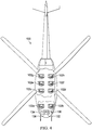
Figures 1A-1B are schematic illustrations of a rotorcraft implementing a modal restraint system in accordance with embodiments of the present disclosure; -
Figures 2A-2C are various views of a seatbelt subsystem in accordance with embodiments of the present disclosure; -
Figures 3A-3C are side views of various modes of a seatbelt subsystem in accordance with embodiments of the present disclosure; -
Figure 4 is a top view of a rotorcraft implementing a modal restraint system in accordance with embodiments of the present disclosure; and -
Figures 5A-5D are various views of seatbelt subsystems having different configurations in accordance with embodiments of the present disclosure. - While the making and using of various embodiments of the present disclosure are discussed in detail below, it should be appreciated that the present disclosure provides many applicable inventive concepts, which can be embodied in a wide variety of specific contexts. The specific embodiments discussed herein are merely illustrative and do not delimit the scope of the present disclosure. In the interest of clarity, all features of an actual implementation may not be described in this specification. It will of course be appreciated that in the development of any such actual embodiment, numerous implementation-specific decisions must be made to achieve the developer's specific goals, such as compliance with system-related and business-related constraints, which will vary from one implementation to another. Moreover, it will be appreciated that such a development effort might be complex and time-consuming but would nevertheless be a routine undertaking for those of ordinary skill in the art having the benefit of this disclosure.
- In the specification, reference may be made to the spatial relationships between various components and to the spatial orientation of various aspects of components as the devices are depicted in the attached drawings. However, as will be recognized by those skilled in the art after a complete reading of the present disclosure, the devices, members, apparatuses, and the like described herein may be positioned in any desired orientation. Thus, the use of terms such as "above," "below," "upper," "lower" or other like terms to describe a spatial relationship between various components or to describe the spatial orientation of aspects of such components should be understood to describe a relative relationship between the components or a spatial orientation of aspects of such components, respectively, as the devices described herein may be oriented in any desired direction. As used herein, the term "coupled" may include direct or indirect coupling by any means, including by mere contact or by moving and/or non-moving mechanical connections.
- Referring to
figures 1A-1B in the drawings, a rotorcraft is schematically illustrated and generally designated 10.Rotorcraft 10 is a helicopter having amain rotor 12, which includes a plurality ofrotor blade assemblies 14.Main rotor 12 is rotatable relative to afuselage 16, which includes acockpit 18 and apassenger cabin 20.Cockpit 18 andpassenger cabin 20 includeseats occupants 26, such as pilots, crewmembers, passengers and the like. The pitch ofrotor blade assemblies 14 can be collectively and/or cyclically manipulated to selectively control direction, thrust and lift ofrotorcraft 10. Alanding gear system 28 provides ground support forrotorcraft 10. Atailboom 30 extends fromfuselage 16. Atail section 32 includes atail rotor 34 that is rotatably coupled to the aft portion oftailboom 30.Tail rotor 34 controls the yaw ofrotorcraft 10. -
Rotorcraft 10 includes amodal restraint system 36, which includes seatbelt, or restraint,subsystems 38a-38e.Seatbelt subsystems cockpit 18 andseatbelt subsystems 38c-38e are located inpassenger cabin 20. Eachseatbelt subsystem 38a-38e is adapted to secure one ofoccupants 26 to arespective seat seatbelt subsystem 38a-38e includes astrap 40 that is selectively retractable into and extendable from astrap feeder unit 42.Seatbelt subsystems 38a-38e may be switched between a plurality of modes including a fixed mode and an unfixed mode. In fixed mode,strap 40 is substantially unextendable fromstrap feeder unit 42. In unfixed mode,strap 40 is extendable from and retractable intostrap feeder unit 42. In some embodiments, the modes ofseatbelt subsystems 38a-38e may include a retracted fixed mode in which strap 40 is retracted intostrap feeder unit 42 to tightenstrap 40 againstoccupants 26. In other embodiments, the modes ofseatbelt subsystems 38a-38e may include an inertia reel mode, a type of unfixed mode, in which strap 40 is retractable into and extendable fromstrap feeder unit 42 unlessstrap 40 is pulled with a force sufficient to preventstrap feeder unit 42 from extendingstrap 40 any further, as may occur if the body of an occupant moves relative torotorcraft 10 orseats - In some embodiments,
seatbelt subsystems 38a-38e are in fixed mode by default, or during normal operation ofrotorcraft 10 in the absence of user, computer or other input to specify the mode ofseatbelt subsystems 38a-38e. In these embodiments,seatbelt subsystems 38a-38e may switch to unfixed mode in response to user input, which increases the freedom of bodily movement ofoccupants 26 relative to theirrespective seats occupant 26 when there is no perceived threat of a life-threatening acceleration event. The interchangeability ofmodal restraint system 36 between various modes providesoccupants 26 with added comfort and mobility, while also fixedly securingoccupants 26 toseats - It should be appreciated that
rotorcraft 10 is merely illustrative of a variety of aircraft that can implement the embodiments disclosed herein. Indeed,modal restraint system 36 may be utilized on any aircraft having one or more occupants. Other aircraft implementations can include hybrid aircraft, tiltrotor aircraft, tiltwing aircraft, quad tiltrotor aircraft, gyrocopters, airplanes and the like. As such, those skilled in the art will recognize thatmodal restraint system 36 can be integrated into a variety of aircraft configurations. It should be appreciated that even though aircraft are particularly well-suited to implement the embodiments of the present disclosure, non-aircraft vehicles and devices can also implement the embodiments. - Referring to
figures 2A-2C in the drawings, a modal restraint system for an aircraft is schematically illustrated and generally designated 100.Modal restraint system 100 includesseatbelt subsystem 102, which securesoccupant 104 toseat 106 usingstrap 108.Strap 108 is positionable adjacent tooccupant 104 so as to at least partially disposeoccupant 104 betweenseat 106 andstrap 108.Strap 108 includes a torso, or shoulder or upper, strap positionable adjacent to the torso ofoccupant 104, and a lap, or lower, strap positionable adjacent to the lap region ofoccupant 104.Strap 108 is selectively retractable into and extendable fromstrap feeder unit 110.Strap feeder unit 110 is in fixed mode by default and is operable to switch to unfixed mode in response to user input, thereby increasing the freedom of forward movement ofoccupant 104 relative toseat 106. Althoughstrap feeder unit 110 is shown to be inside ofseat 106 near the shoulder ofoccupant 104,strap feeder unit 110 may be located elsewhere proximate toseat 106. It will be appreciated by one of ordinary skill in the art that strap 108 is merely illustrative of a three-point restraint system, although in other embodiments the restraint system may include more or less than three fixation points. -
Strap feeder unit 110 includes aspool 112 operable to rotate in either afirst direction 114 or asecond direction 116 to wind or unwindstrap 108 thereabout, respectively.Strap feeder unit 110 includes alocking module 118 that is operable to engage, mechanically and/or electromagnetically, withspool 112 whenstrap feeder unit 110 is in fixed mode to impedespool 112 from rotating insecond direction 116, thereby renderingstrap 108 substantially unextendable.Strap feeder unit 110 includes aretraction module 120 that is operable to retractstrap 108 intostrap feeder unit 110 by, for example,rotating spool 112 infirst direction 114, thereby tighteningstrap 108 againstoccupant 104. The fixed mode may include a retracted fixed mode in whichretraction module 120 retractsstrap 108 intostrap feeder unit 110. In retracted fixed mode, the slack instrap 108 may be substantially reduced or minimized such that less than two fingers fit betweenstrap 108 and the body ofoccupant 104.Retraction module 120 may preloadstrap 108 using an electromagnetic tensioner, a mechanical pretensioner or any other strap-retracting technique or mechanism. The unfixed mode may include an inertia reel mode implemented by aninertia reel subassembly 122 that is selectively engageable withspool 112.Inertia reel subassembly 122 may utilize a weighted pendulum, a centrifugal clutch, an electromagnetic mechanism or any other inertia reel implementations known by one of ordinary skill in the art. Depending on the embodiment,strap feeder unit 110 may switch to either unfixed mode or inertia reel mode in response to the user input. -
Seatbelt subsystem 102 includes arelease selector 124 in communication withstrap feeder unit 110.Release selector 124 may be any input device such as a voice-activated input, lever, knob, foot pedal or pull cord.Release selector 124 may be in mechanical, electrical, wireless, computer or any other type of communication withstrap feeder unit 110. The user input that causesseatbelt subsystem 102 to switch to unfixed mode or inertia reel mode may be the selection ofrelease selector 124 byoccupant 104.Release selector 124 may be switchable between a release position and an unrelease position. In such embodiments, the user input causingseatbelt subsystem 102 to switch to unfixed mode or inertia reel mode may be switchingrelease selector 124 from the unrelease position to the release position. In the illustrated embodiment,release selector 124 is a button 126.Occupant 104 may press button 126 to causeseatbelt subsystem 102 to switch to unfixed mode or inertia reel mode. Furthermore,strap feeder unit 110 may switch to default fixed mode or retracted fixed mode in response tooccupant 104 releasing button 126. While button 126 is shown to be proximate to strap 108, button 126 may be located elsewhere, such as on a cellular phone or other personal communication device ofoccupant 104. Button 126 may be a mechanical button or a digital button, such as an icon on a touchscreen. - Referring to
figures 3A-3C in the drawings, a sequence of events illustrating the various modes ofseatbelt subsystem 102 is schematically illustrated. Infigure 3A ,seatbelt subsystem 102 is in default fixed mode or retracted fixed mode. In either of these modes,occupant 104 is in a substantially fixed and secured position againstseat 106 to prevent forward, upward or downward motion of the head or body ofoccupant 104 should an acceleration event, such as an HIC event or a life-threatening acceleration event, occur. Comfort and mobility is limited whileseatbelt subsystem 102 is in fixed mode or retracted fixed mode. To remedy this lack of comfort and mobility,occupant 104 may press release button 126, as shown infigure 3B , to causestrap feeder unit 110 to switch to either unfixed mode or inertia reel mode, as shown infigure 3C , thus providingoccupant 104 with freedom of forward movement. Such freedom of forward movement providesoccupant 104 with additional comfort and allowsoccupant 104 to extend his or her area of reach, including looking out ofnearby windows 122. - In some embodiments,
seatbelt subsystem 102 may be in unfixed mode or inertia reel mode temporarily before reverting or switching back to fixed mode or retracted fixed mode. For example,strap feeder unit 110 may switch to default fixed mode or retracted fixed mode in response to a cessation of user input (i.e.,occupant 104 stops pressing button 126). In other embodiments,strap feeder unit 110 may revert back to fixed mode or retracted fixed mode in response to a cessation of a predetermined time period. For example,seatbelt subsystem 102 may stay in unfixed mode or inertia reel mode for a time period that commences uponoccupant 104 selecting button 126, as shown infigure 3B , and ending at a predetermined period of time afteroccupant 104 selects button 126. The predetermined time period may be on the order of seconds, minutes or hours, depending on the embodiment. In other embodiments, pressing button 126 a first time may causeseatbelt subsystem 102 to switch to unfixed mode or inertia reel mode and pressing button 126 a second time may causeseatbelt subsystem 102 to revert or switch to default fixed mode or retracted fixed mode. - In yet other embodiments,
strap feeder unit 110 may revert or switch to default fixed mode or retracted fixed mode in response to a precautionary event, or collision-risk or acceleration-risk condition, thereby reducing the freedom of movement ofoccupant 104 relative toseat 106 of the aircraft. The precautionary event, which triggersseatbelt subsystem 102 to return to retracted fixed mode, may anticipate a life-threatening acceleration event, such as a hard landing, a collision, an uncontrolled descent, extreme turbulence, an HIC event or any other acceleration event with the potential to be injurious or fatal to a human being. It will be appreciated by one of ordinary skill in the art that the precautionary event triggeringseatbelt subsystem 102 to switch to retracted fixed mode may occur well before acceleratory, inertia or other involuntary motion ofoccupant 104 caused by the acceleration of the aircraft, thereby reducing the delay in securingoccupant 104 toseat 106 as compared to traditional inertia reel seatbelts. Because the precautionary event may anticipate or occur prior to a life-threatening acceleration event, returning to retracted fixed mode in response to a precautionary event reduces the freedom of movement ofoccupant 104 during a life-threatening acceleration event, thereby enhancing the safety ofoccupant 104.Release selector 124 may also be disabled in response to a precautionary event, thereby preventingstrap feeder unit 110 from switching to unfixed mode or inertia reel mode. - Referring to
figure 4 in the drawings, a rotorcraft implementingmodal restraint system 100 is schematically illustrated and generally designated 130.Modal restraint system 100 includes amaster release selector 132 located incockpit 134.Master release selector 132 may be selected by an occupant ofcockpit 134, such as a pilot.Master release selector 132 is in communication with each ofseatbelt subsystems 102a-102h, including by mechanical, electrical, computer, wireless or any other form of communication. Selection ofmaster release selector 132 causes or allows the strap feeder units of all or a portion ofseatbelt subsystems 102a-102h to switch to unfixed mode or inertia reel mode. In some embodiments,master release selector 132 may override the individual release selectors operated by the respective occupants of each ofseatbelt subsystems 102a-102h. The strap feeder units of each ofseatbelt subsystems 102a-102h may additionally be operable to switch to retracted fixed mode in response to a precautionary event. In some embodiments,master release selector 132 and/or the release selector(s) for each ofseatbelt subsystems 102a-102h may be disabled in response torotorcraft 130 switching to instrument flight rules operation mode.Modal restraint system 100 may also includemaster lock selector 136, enabling an occupant ofcockpit 134 to selectmaster release selector 132 to switchmodal restraint system 100 to unfixed mode or inertia reel mode and selectmaster lock selector 136 to switchmodal restraint system 100 to fixed mode or retracted fixed mode. Furthermore, each ofseatbelt subsystems 102a-102h may include both arelease selector 124 and a lock selector (not shown), which switches therespective seatbelt subsystem 102a-102h to fixed mode or retracted fixed mode. The default mode ofmodal restraint system 100 may be reversible or changeable by a pilot, ground technician, occupant or other person. Furthermore, the default mode ofseatbelt subsystems 102a-102h may be individually or collectively reversible or changeable. For example, a pilot may change the default mode ofmodal restraint system 100 from unfixed mode to fixed mode, or vice versa, depending on the circumstances. - Referring to
figures 5A-5D in the drawings, various configurations of a seatbelt subsystem are schematically illustrated. Infigure 5A ,seatbelt subsystem 200 includes apull cord 202.Pull cord 202 may be a release selector. Infigure 5B ,seatbelt subsystem 204 includes alever 206. In some embodiments,lever 206 may be a release selector rotatable between a release position and an unrelease position, androtating lever 206 from the unrelease position to the release position may causeseatbelt subsystem 204 to switch to unfixed mode or inertia reel mode. Infigure 5C ,seatbelt subsystem 208 includes arotatable knob 210.Knob 210 is rotatable in either ofdirections 212 to either loosen or tightenstrap 214. For example, ifoccupant 216 perceives the possibility of an imminent acceleration event,occupant 216 may rotateknob 210 to tightenstrap 214. Conversely,occupant 216 may rotateknob 210 to loosenstrap 214 if he or she desires comfort or mobility.Knob 210 allowsoccupant 216 to more precisely select the looseness or tightness ofstrap 214 within a range of looseness/tightness settings. In other embodiments,seatbelt subsystem 208 may include a foot pedal release selector. Infigure 5D ,seatbelt subsystem 218 includes fourtorso straps hub unit 228, which may include either or both ofrelease selector 230 or alock selector 232, the latter of which switchesseatbelt subsystem 218 to fixed mode or retracted fixed mode. In contrast to previously illustrated embodiments,hub unit 228 is located proximate to the chest area ofoccupant 234, placingrelease selector 230 and/orlock selector 232 within easy reach ofoccupant 234. - The foregoing description of embodiments of the disclosure has been presented for purposes of illustration and description. It is not intended to be exhaustive or to limit the disclosure to the precise form disclosed, and modifications and variations are possible in light of the above teachings or may be acquired from practice of the disclosure. The embodiments were chosen and described in order to explain the principals of the disclosure and its practical application to enable one skilled in the art to utilize the disclosure in various embodiments and with various modifications as are suited to the particular use contemplated. Other substitutions, modifications, changes and omissions may be made in the design, operating conditions and arrangement of the embodiments without departing from the scope of the present disclosure. Such modifications and combinations of the illustrative embodiments as well as other embodiments will be apparent to persons skilled in the art upon reference to the description. It is, therefore, intended that the appended claims encompass any such modifications or embodiments.
Claims (16)
- A modal restraint system for an occupant of a seat of an aircraft comprising:a strap feeder unit; anda strap selectively retractable into and extendable from the strap feeder unit, the strap positionable adjacent to the occupant so as to at least partially dispose the occupant between the strap and the seat;wherein, the strap feeder unit is adapted to switch between a plurality of modes including a fixed mode and an unfixed mode, the strap substantially unextendable from the strap feeder unit in the fixed mode, the strap extendable from and retractable into the strap feeder unit in the unfixed mode;wherein, the strap feeder unit is in the fixed mode by default; andwherein, the strap feeder unit is operable to switch to the unfixed mode in response to a user input, thereby increasing freedom of movement of the occupant relative to the seat of the aircraft.
- The modal restraint system as recited in claim 1, wherein the strap feeder unit further comprises a spool operable to rotate in first and second directions to wind and unwind the strap thereabout, respectively.
- The modal restraint system as recited in claim 2, wherein the strap feeder unit further comprises a locking module, the locking module engaging with the spool when the strap feeder unit is in the fixed mode to impede the spool from rotating in the second direction such that the strap is substantially unextendable.
- The modal restraint system as recited in claim 2 or in claim 3, wherein the plurality of modes further comprise a retracted fixed mode and the strap feeder unit further comprises a retraction module adapted to rotate the spool in the first direction to retract the strap into the strap feeder unit in the retracted fixed mode, thereby tightening the strap against the occupant.
- The modal restraint system as recited in claim 2 or in claim 3 or in claim 4, wherein the unfixed mode further comprises an inertia reel mode; and
wherein the strap feeder unit further comprises an inertia reel subassembly selectively engagable with the spool in the inertia reel mode. - The modal restraint system as recited in claim 1 or in any preceding claim, wherein the strap further comprises a torso strap positionable adjacent to the torso of the occupant and a lap strap positionable adjacent to the lap region of the occupant.
- The modal restraint system as recited in claim 1 or in any preceding claim, wherein the plurality of modes further comprise a retracted fixed mode and wherein the strap feeder unit is adapted to retract the strap into the strap feeder unit in the retracted fixed mode, thereby tightening the strap against the occupant.
- The modal restraint system as recited in claim 1 or in any preceding claim, wherein the strap feeder unit is further operable to return to the fixed mode in response to a cessation of the user input.
- The modal restraint system as recited in claim 1 or in any preceding claim, wherein:(i) the strap feeder unit is further operable to return to the fixed mode in response to a cessation of a predetermined time period; and/or(ii) the strap feeder unit automatically returns to the fixed mode in response to a precautionary event.
- The modal restraint system as recited in claim 1 or in any preceding claim, further comprising a release selector in communication with the strap feeder unit and wherein the user input further comprises selection of the release selector by the occupant.
- The modal restraint system as recited in claim 10, wherein the release selector is switchable between a release position and an unrelease position; and
wherein the user input further comprises switching the release selector from the unrelease position to the release position. - The modal restraint system as recited in claim 10 or claim 11, wherein:(i) the release selector further comprises an input device selected from the group consisting of a button, a lever, a knob or a pull cord; and/or(ii) the release selector is proximate to the seat.
- The modal restraint system as recited in claim 10 or in claim 11 or in claim 12, wherein the release selector is disabled in response to a precautionary event, thereby preventing the strap feeder unit from switching to the unfixed mode.
- An aircraft comprising:a fuselage;a plurality of seats in the fuselage; anda modal restraint system including a plurality of seatbelt subsystems, each seatbelt subsystem adapted to secure an occupant to one of the seats, each seatbelt subsystem comprising:a strap feeder unit; anda strap selectively retractable into and extendable from the strap feeder unit, the strap positionable adjacent to the occupant so as to at least partially dispose the occupant between the strap and the seat;wherein, the strap feeder unit is adapted to switch between a plurality of modes including a fixed mode and an unfixed mode, the strap substantially unextendable from the strap feeder unit in the fixed mode, the strap extendable from and retractable into the strap feeder unit in the unfixed mode;wherein, the strap feeder unit is in the fixed mode by default; andwherein, the strap feeder unit is operable to switch to the unfixed mode in response to a user input, thereby increasing freedom of movement of the occupant relative to the seat.
- The aircraft as recited in claim 14 wherein the modal restraint system further comprises a master release selector in communication with each of the seatbelt subsystems;
wherein the user input further comprises selection of the master release selector; and
wherein the selection of the master release selector causes the strap feeder units of each of the seatbelt subsystems to switch to the unfixed mode; and optionally or preferably wherein the fuselage further comprises a cockpit; and
wherein the master release selector is located in the cockpit and selectable by a pilot. - The aircraft as recited in claim 14 or claim 15 wherein the plurality of modes further comprise an inertia reel unfixed mode and a retracted fixed mode; and
wherein the strap feeder units of each of the seatbelt subsystems are operable to switch to the retracted fixed mode in response to a precautionary event; and/or
the aircraft further comprising:a release selector in communication with the strap feeder unit; anda plurality of flight operation modes including a visual flight rules operation mode and an instrument flight rules operation mode;wherein the release selector is disabled in response to switching to the instrument flight rules operation mode.
Applications Claiming Priority (1)
| Application Number | Priority Date | Filing Date | Title |
|---|---|---|---|
| US15/832,689 US10752360B2 (en) | 2017-12-05 | 2017-12-05 | Aircraft restraint systems with fixed default mode |
Publications (2)
| Publication Number | Publication Date |
|---|---|
| EP3498543A1 true EP3498543A1 (en) | 2019-06-19 |
| EP3498543B1 EP3498543B1 (en) | 2019-12-04 |
Family
ID=64426681
Family Applications (1)
| Application Number | Title | Priority Date | Filing Date |
|---|---|---|---|
| EP18207393.2A Active EP3498543B1 (en) | 2017-12-05 | 2018-11-20 | Aircraft restraint systems with fixed default mode |
Country Status (3)
| Country | Link |
|---|---|
| US (1) | US10752360B2 (en) |
| EP (1) | EP3498543B1 (en) |
| CN (1) | CN109941441B (en) |
Families Citing this family (2)
| Publication number | Priority date | Publication date | Assignee | Title |
|---|---|---|---|---|
| US11565791B2 (en) | 2021-04-15 | 2023-01-31 | Ami Industries, Inc. | Sensor-based ejection initiation system |
| US11975841B2 (en) | 2022-10-03 | 2024-05-07 | Rockwell Collins, Inc. | Biometrically actuated occupant restraint system and method for a vehicle |
Citations (3)
| Publication number | Priority date | Publication date | Assignee | Title |
|---|---|---|---|---|
| DE2525144A1 (en) * | 1975-06-06 | 1976-12-23 | Roemer Wingard Autogurte Gmbh | HOLDING AND SECURING DEVICE FOR OPERATING PERSONNEL IN THE CAB OF EARTH CONSTRUCTION MACHINERY |
| US20090261568A1 (en) * | 2008-04-22 | 2009-10-22 | Freescale Semiconductor, Inc. | Vehicular seatbelt restraint with selectively disabled inertia reel assembly |
| EP2275312A1 (en) * | 2009-07-06 | 2011-01-19 | Schroth Safety Products GmbH | Safety belt |
Family Cites Families (19)
| Publication number | Priority date | Publication date | Assignee | Title |
|---|---|---|---|---|
| US2899146A (en) * | 1959-08-11 | barecki | ||
| US2480335A (en) * | 1945-04-09 | 1949-08-30 | American Seating Co | Automatic reel |
| US2845234A (en) | 1953-12-03 | 1958-07-29 | Safety apparatus | |
| US3386683A (en) * | 1966-02-10 | 1968-06-04 | Mc Donnell Douglas Corp | Power retraction inertia reel |
| US4277037A (en) | 1980-01-30 | 1981-07-07 | General Motors Corporation | Lock bar release for inertia locking seat belt retractor |
| US4566649A (en) | 1984-06-25 | 1986-01-28 | Irvin Industries Inc. | Conversion control for combination VSI and ALR retractor |
| US4667904A (en) * | 1984-09-28 | 1987-05-26 | The Boeing Company | Torso restraint with in flight and ejection activation modes |
| US4732409A (en) | 1986-12-12 | 1988-03-22 | American Safety Equipment Corporation | Dual mode passenger restraint system |
| DE19758498C2 (en) * | 1997-11-11 | 2001-07-05 | Giok Djien Go | Restraint system with shoulder and / or neck holder to increase occupant protection |
| US6888475B2 (en) | 2002-01-10 | 2005-05-03 | Joshua Scott Darr | Control system for aircraft seat belt arrangement |
| US6746049B2 (en) | 2002-07-24 | 2004-06-08 | Visteon Global Technologies, Inc. | Adaptive seat belt tensioning system |
| US20040036345A1 (en) | 2002-08-20 | 2004-02-26 | Trw Vehicle Safety Systems Inc. & Trw Occupant Restraint Systems Gmbh & Co. Kg | Four-point seat belt having electric motor driven retractor |
| JP2005263176A (en) | 2004-03-22 | 2005-09-29 | Denso Corp | Seat belt device |
| US7318607B2 (en) | 2004-10-19 | 2008-01-15 | Autoliv Asp, Inc. | Adaptive restraint system with retractor pretensioner |
| NO329001B1 (en) | 2008-09-04 | 2010-07-19 | Sigve Rosvik | Withdrawal system for a pilot |
| CN201553052U (en) * | 2009-08-14 | 2010-08-18 | 林碧芬 | Auxiliary air charging band device and auxiliary supporting band device |
| JP5317945B2 (en) * | 2009-12-15 | 2013-10-16 | タカタ株式会社 | Seat belt retractor and seat belt device provided with the same |
| CN109311446B (en) | 2016-03-31 | 2021-10-22 | B/E航空公司 | System and method for protecting passengers in a tilt-mounted aircraft seat |
| CN106218897B (en) * | 2016-08-31 | 2018-03-20 | 北京安达维尔航空设备有限公司 | The helicopter flight engineer's seat folded completely can be achieved |
-
2017
- 2017-12-05 US US15/832,689 patent/US10752360B2/en active Active
-
2018
- 2018-11-20 EP EP18207393.2A patent/EP3498543B1/en active Active
- 2018-12-05 CN CN201811479471.XA patent/CN109941441B/en active Active
Patent Citations (3)
| Publication number | Priority date | Publication date | Assignee | Title |
|---|---|---|---|---|
| DE2525144A1 (en) * | 1975-06-06 | 1976-12-23 | Roemer Wingard Autogurte Gmbh | HOLDING AND SECURING DEVICE FOR OPERATING PERSONNEL IN THE CAB OF EARTH CONSTRUCTION MACHINERY |
| US20090261568A1 (en) * | 2008-04-22 | 2009-10-22 | Freescale Semiconductor, Inc. | Vehicular seatbelt restraint with selectively disabled inertia reel assembly |
| EP2275312A1 (en) * | 2009-07-06 | 2011-01-19 | Schroth Safety Products GmbH | Safety belt |
Also Published As
| Publication number | Publication date |
|---|---|
| US10752360B2 (en) | 2020-08-25 |
| CN109941441B (en) | 2023-01-03 |
| US20190168878A1 (en) | 2019-06-06 |
| EP3498543B1 (en) | 2019-12-04 |
| CN109941441A (en) | 2019-06-28 |
Similar Documents
| Publication | Publication Date | Title |
|---|---|---|
| US11597521B2 (en) | Aircraft restraint systems with unfixed default mode | |
| EP3010376B1 (en) | Compact aircraft cabin attendant seat | |
| US5125598A (en) | Pivoting energy attenuating seat | |
| EP3498543B1 (en) | Aircraft restraint systems with fixed default mode | |
| US9828100B2 (en) | Aircraft seat with taxi, takeoff and landing lie flat capability | |
| US10414501B2 (en) | Seat back breakover with dynamically triggered actuator | |
| EP3277583B1 (en) | Adjustable headrest enabling sideward leaning and seclusion | |
| US8046846B2 (en) | Helmet restraint system | |
| US10391898B1 (en) | Torso equipment support system (TESS) | |
| WO2017008015A1 (en) | Aircraft passenger restraint system with three-point seat belt and structural mounted airbag | |
| US2892602A (en) | Aircraft ejectable seat with automatically releasable person attaching harness | |
| US11059587B2 (en) | Seat back decoupler mechanism | |
| US2707087A (en) | Method and means for increasing airplane pilot's resistance to acceleration forces | |
| EP2646320A1 (en) | Seat belt attachment for aircraft seat | |
| EP4353596A2 (en) | Offset helicopter pilot seat with singular energy absorber | |
| EP4253146A1 (en) | Active neck injury reduction devices | |
| US20240017853A1 (en) | Seat System and Cabin Area for Use in a Crew Escape System of a Space Transport Vehicle | |
| Lewis | Restraint systems and escape from aircraft | |
| GR2003198Y (en) | Radio receiver on energy absorption element for aircraft and unmanned aircraft parachutes | |
| CN112937871A (en) | Anti-bumping equipment for civil aircraft | |
| CN114476089A (en) | Control system and method for avoiding misoperation of pilot during air separation and reset | |
| Woollard | A COMPARATIVE EVALUANON OF GLIDER PARACHUTE RESCUE SYSTEM DESIGN ASPECTS | |
| Meintjes et al. | The Development of a New Concept for Pilot Protection |
Legal Events
| Date | Code | Title | Description |
|---|---|---|---|
| PUAI | Public reference made under article 153(3) epc to a published international application that has entered the european phase |
Free format text: ORIGINAL CODE: 0009012 |
|
| STAA | Information on the status of an ep patent application or granted ep patent |
Free format text: STATUS: REQUEST FOR EXAMINATION WAS MADE |
|
| STAA | Information on the status of an ep patent application or granted ep patent |
Free format text: STATUS: EXAMINATION IS IN PROGRESS |
|
| 17P | Request for examination filed |
Effective date: 20181120 |
|
| AK | Designated contracting states |
Kind code of ref document: A1 Designated state(s): AL AT BE BG CH CY CZ DE DK EE ES FI FR GB GR HR HU IE IS IT LI LT LU LV MC MK MT NL NO PL PT RO RS SE SI SK SM TR |
|
| AX | Request for extension of the european patent |
Extension state: BA ME |
|
| 17Q | First examination report despatched |
Effective date: 20190603 |
|
| GRAP | Despatch of communication of intention to grant a patent |
Free format text: ORIGINAL CODE: EPIDOSNIGR1 |
|
| STAA | Information on the status of an ep patent application or granted ep patent |
Free format text: STATUS: GRANT OF PATENT IS INTENDED |
|
| INTG | Intention to grant announced |
Effective date: 20190906 |
|
| RIN1 | Information on inventor provided before grant (corrected) |
Inventor name: SINUSAS, ERIC A. Inventor name: NOISEUX-BOUCHER, GUILLAUME Inventor name: DUVAL, SEBASTIEN Inventor name: LOVELAND, STEVE Inventor name: BOISVERT, OLIVIER ANDRE |
|
| GRAS | Grant fee paid |
Free format text: ORIGINAL CODE: EPIDOSNIGR3 |
|
| GRAA | (expected) grant |
Free format text: ORIGINAL CODE: 0009210 |
|
| STAA | Information on the status of an ep patent application or granted ep patent |
Free format text: STATUS: THE PATENT HAS BEEN GRANTED |
|
| AK | Designated contracting states |
Kind code of ref document: B1 Designated state(s): AL AT BE BG CH CY CZ DE DK EE ES FI FR GB GR HR HU IE IS IT LI LT LU LV MC MK MT NL NO PL PT RO RS SE SI SK SM TR |
|
| REG | Reference to a national code |
Ref country code: GB Ref legal event code: FG4D |
|
| REG | Reference to a national code |
Ref country code: CH Ref legal event code: EP |
|
| REG | Reference to a national code |
Ref country code: AT Ref legal event code: REF Ref document number: 1209006 Country of ref document: AT Kind code of ref document: T Effective date: 20191215 |
|
| REG | Reference to a national code |
Ref country code: DE Ref legal event code: R096 Ref document number: 602018001489 Country of ref document: DE |
|
| REG | Reference to a national code |
Ref country code: IE Ref legal event code: FG4D |
|
| REG | Reference to a national code |
Ref country code: NL Ref legal event code: MP Effective date: 20191204 |
|
| REG | Reference to a national code |
Ref country code: LT Ref legal event code: MG4D |
|
| PG25 | Lapsed in a contracting state [announced via postgrant information from national office to epo] |
Ref country code: FI Free format text: LAPSE BECAUSE OF FAILURE TO SUBMIT A TRANSLATION OF THE DESCRIPTION OR TO PAY THE FEE WITHIN THE PRESCRIBED TIME-LIMIT Effective date: 20191204 Ref country code: LT Free format text: LAPSE BECAUSE OF FAILURE TO SUBMIT A TRANSLATION OF THE DESCRIPTION OR TO PAY THE FEE WITHIN THE PRESCRIBED TIME-LIMIT Effective date: 20191204 Ref country code: SE Free format text: LAPSE BECAUSE OF FAILURE TO SUBMIT A TRANSLATION OF THE DESCRIPTION OR TO PAY THE FEE WITHIN THE PRESCRIBED TIME-LIMIT Effective date: 20191204 Ref country code: BG Free format text: LAPSE BECAUSE OF FAILURE TO SUBMIT A TRANSLATION OF THE DESCRIPTION OR TO PAY THE FEE WITHIN THE PRESCRIBED TIME-LIMIT Effective date: 20200304 Ref country code: LV Free format text: LAPSE BECAUSE OF FAILURE TO SUBMIT A TRANSLATION OF THE DESCRIPTION OR TO PAY THE FEE WITHIN THE PRESCRIBED TIME-LIMIT Effective date: 20191204 Ref country code: GR Free format text: LAPSE BECAUSE OF FAILURE TO SUBMIT A TRANSLATION OF THE DESCRIPTION OR TO PAY THE FEE WITHIN THE PRESCRIBED TIME-LIMIT Effective date: 20200305 Ref country code: NO Free format text: LAPSE BECAUSE OF FAILURE TO SUBMIT A TRANSLATION OF THE DESCRIPTION OR TO PAY THE FEE WITHIN THE PRESCRIBED TIME-LIMIT Effective date: 20200304 |
|
| PG25 | Lapsed in a contracting state [announced via postgrant information from national office to epo] |
Ref country code: RS Free format text: LAPSE BECAUSE OF FAILURE TO SUBMIT A TRANSLATION OF THE DESCRIPTION OR TO PAY THE FEE WITHIN THE PRESCRIBED TIME-LIMIT Effective date: 20191204 Ref country code: HR Free format text: LAPSE BECAUSE OF FAILURE TO SUBMIT A TRANSLATION OF THE DESCRIPTION OR TO PAY THE FEE WITHIN THE PRESCRIBED TIME-LIMIT Effective date: 20191204 |
|
| PG25 | Lapsed in a contracting state [announced via postgrant information from national office to epo] |
Ref country code: AL Free format text: LAPSE BECAUSE OF FAILURE TO SUBMIT A TRANSLATION OF THE DESCRIPTION OR TO PAY THE FEE WITHIN THE PRESCRIBED TIME-LIMIT Effective date: 20191204 |
|
| PG25 | Lapsed in a contracting state [announced via postgrant information from national office to epo] |
Ref country code: PT Free format text: LAPSE BECAUSE OF FAILURE TO SUBMIT A TRANSLATION OF THE DESCRIPTION OR TO PAY THE FEE WITHIN THE PRESCRIBED TIME-LIMIT Effective date: 20200429 Ref country code: RO Free format text: LAPSE BECAUSE OF FAILURE TO SUBMIT A TRANSLATION OF THE DESCRIPTION OR TO PAY THE FEE WITHIN THE PRESCRIBED TIME-LIMIT Effective date: 20191204 Ref country code: NL Free format text: LAPSE BECAUSE OF FAILURE TO SUBMIT A TRANSLATION OF THE DESCRIPTION OR TO PAY THE FEE WITHIN THE PRESCRIBED TIME-LIMIT Effective date: 20191204 Ref country code: EE Free format text: LAPSE BECAUSE OF FAILURE TO SUBMIT A TRANSLATION OF THE DESCRIPTION OR TO PAY THE FEE WITHIN THE PRESCRIBED TIME-LIMIT Effective date: 20191204 Ref country code: CZ Free format text: LAPSE BECAUSE OF FAILURE TO SUBMIT A TRANSLATION OF THE DESCRIPTION OR TO PAY THE FEE WITHIN THE PRESCRIBED TIME-LIMIT Effective date: 20191204 Ref country code: ES Free format text: LAPSE BECAUSE OF FAILURE TO SUBMIT A TRANSLATION OF THE DESCRIPTION OR TO PAY THE FEE WITHIN THE PRESCRIBED TIME-LIMIT Effective date: 20191204 |
|
| PG25 | Lapsed in a contracting state [announced via postgrant information from national office to epo] |
Ref country code: SM Free format text: LAPSE BECAUSE OF FAILURE TO SUBMIT A TRANSLATION OF THE DESCRIPTION OR TO PAY THE FEE WITHIN THE PRESCRIBED TIME-LIMIT Effective date: 20191204 Ref country code: IS Free format text: LAPSE BECAUSE OF FAILURE TO SUBMIT A TRANSLATION OF THE DESCRIPTION OR TO PAY THE FEE WITHIN THE PRESCRIBED TIME-LIMIT Effective date: 20200404 Ref country code: SK Free format text: LAPSE BECAUSE OF FAILURE TO SUBMIT A TRANSLATION OF THE DESCRIPTION OR TO PAY THE FEE WITHIN THE PRESCRIBED TIME-LIMIT Effective date: 20191204 |
|
| REG | Reference to a national code |
Ref country code: DE Ref legal event code: R097 Ref document number: 602018001489 Country of ref document: DE |
|
| REG | Reference to a national code |
Ref country code: AT Ref legal event code: MK05 Ref document number: 1209006 Country of ref document: AT Kind code of ref document: T Effective date: 20191204 |
|
| PLBE | No opposition filed within time limit |
Free format text: ORIGINAL CODE: 0009261 |
|
| STAA | Information on the status of an ep patent application or granted ep patent |
Free format text: STATUS: NO OPPOSITION FILED WITHIN TIME LIMIT |
|
| PG25 | Lapsed in a contracting state [announced via postgrant information from national office to epo] |
Ref country code: DK Free format text: LAPSE BECAUSE OF FAILURE TO SUBMIT A TRANSLATION OF THE DESCRIPTION OR TO PAY THE FEE WITHIN THE PRESCRIBED TIME-LIMIT Effective date: 20191204 |
|
| 26N | No opposition filed |
Effective date: 20200907 |
|
| PG25 | Lapsed in a contracting state [announced via postgrant information from national office to epo] |
Ref country code: AT Free format text: LAPSE BECAUSE OF FAILURE TO SUBMIT A TRANSLATION OF THE DESCRIPTION OR TO PAY THE FEE WITHIN THE PRESCRIBED TIME-LIMIT Effective date: 20191204 Ref country code: PL Free format text: LAPSE BECAUSE OF FAILURE TO SUBMIT A TRANSLATION OF THE DESCRIPTION OR TO PAY THE FEE WITHIN THE PRESCRIBED TIME-LIMIT Effective date: 20191204 |
|
| PG25 | Lapsed in a contracting state [announced via postgrant information from national office to epo] |
Ref country code: MC Free format text: LAPSE BECAUSE OF FAILURE TO SUBMIT A TRANSLATION OF THE DESCRIPTION OR TO PAY THE FEE WITHIN THE PRESCRIBED TIME-LIMIT Effective date: 20191204 |
|
| PG25 | Lapsed in a contracting state [announced via postgrant information from national office to epo] |
Ref country code: LU Free format text: LAPSE BECAUSE OF NON-PAYMENT OF DUE FEES Effective date: 20201120 |
|
| REG | Reference to a national code |
Ref country code: BE Ref legal event code: MM Effective date: 20201130 |
|
| PG25 | Lapsed in a contracting state [announced via postgrant information from national office to epo] |
Ref country code: IE Free format text: LAPSE BECAUSE OF NON-PAYMENT OF DUE FEES Effective date: 20201120 |
|
| PG25 | Lapsed in a contracting state [announced via postgrant information from national office to epo] |
Ref country code: TR Free format text: LAPSE BECAUSE OF FAILURE TO SUBMIT A TRANSLATION OF THE DESCRIPTION OR TO PAY THE FEE WITHIN THE PRESCRIBED TIME-LIMIT Effective date: 20191204 Ref country code: MT Free format text: LAPSE BECAUSE OF FAILURE TO SUBMIT A TRANSLATION OF THE DESCRIPTION OR TO PAY THE FEE WITHIN THE PRESCRIBED TIME-LIMIT Effective date: 20191204 Ref country code: CY Free format text: LAPSE BECAUSE OF FAILURE TO SUBMIT A TRANSLATION OF THE DESCRIPTION OR TO PAY THE FEE WITHIN THE PRESCRIBED TIME-LIMIT Effective date: 20191204 |
|
| PG25 | Lapsed in a contracting state [announced via postgrant information from national office to epo] |
Ref country code: MK Free format text: LAPSE BECAUSE OF FAILURE TO SUBMIT A TRANSLATION OF THE DESCRIPTION OR TO PAY THE FEE WITHIN THE PRESCRIBED TIME-LIMIT Effective date: 20191204 |
|
| REG | Reference to a national code |
Ref country code: CH Ref legal event code: PL |
|
| PG25 | Lapsed in a contracting state [announced via postgrant information from national office to epo] |
Ref country code: BE Free format text: LAPSE BECAUSE OF NON-PAYMENT OF DUE FEES Effective date: 20201130 |
|
| PG25 | Lapsed in a contracting state [announced via postgrant information from national office to epo] |
Ref country code: LI Free format text: LAPSE BECAUSE OF NON-PAYMENT OF DUE FEES Effective date: 20211130 Ref country code: CH Free format text: LAPSE BECAUSE OF NON-PAYMENT OF DUE FEES Effective date: 20211130 |
|
| P01 | Opt-out of the competence of the unified patent court (upc) registered |
Effective date: 20230602 |
|
| PG25 | Lapsed in a contracting state [announced via postgrant information from national office to epo] |
Ref country code: SI Free format text: LAPSE BECAUSE OF FAILURE TO SUBMIT A TRANSLATION OF THE DESCRIPTION OR TO PAY THE FEE WITHIN THE PRESCRIBED TIME-LIMIT Effective date: 20191204 |
|
| PGFP | Annual fee paid to national office [announced via postgrant information from national office to epo] |
Ref country code: GB Payment date: 20231127 Year of fee payment: 6 |
|
| PGFP | Annual fee paid to national office [announced via postgrant information from national office to epo] |
Ref country code: IT Payment date: 20231122 Year of fee payment: 6 Ref country code: FR Payment date: 20231127 Year of fee payment: 6 Ref country code: DE Payment date: 20231129 Year of fee payment: 6 |