US8046846B2 - Helmet restraint system - Google Patents

Helmet restraint system Download PDF

Info

Publication number
US8046846B2
US8046846B2 US11/700,097 US70009707A US8046846B2 US 8046846 B2 US8046846 B2 US 8046846B2 US 70009707 A US70009707 A US 70009707A US 8046846 B2 US8046846 B2 US 8046846B2
Authority
US
United States
Prior art keywords
helmet
buckle strap
restraint system
garment
fixing point
Prior art date
Legal status (The legal status is an assumption and is not a legal conclusion. Google has not performed a legal analysis and makes no representation as to the accuracy of the status listed.)
Active, expires
Application number
US11/700,097
Other versions
US20110093999A1 (en
Inventor
Jimmie Karlsson
Maria Martikkala
Current Assignee (The listed assignees may be inaccurate. Google has not performed a legal analysis and makes no representation or warranty as to the accuracy of the list.)
Saab AB
Original Assignee
Saab AB
Priority date (The priority date is an assumption and is not a legal conclusion. Google has not performed a legal analysis and makes no representation as to the accuracy of the date listed.)
Filing date
Publication date
Application filed by Saab AB filed Critical Saab AB
Assigned to SAAB AB reassignment SAAB AB ASSIGNMENT OF ASSIGNORS INTEREST (SEE DOCUMENT FOR DETAILS). Assignors: MARTIKKALA, MARIA, KARLSSON, JIMMIE
Publication of US20110093999A1 publication Critical patent/US20110093999A1/en
Application granted granted Critical
Publication of US8046846B2 publication Critical patent/US8046846B2/en
Active legal-status Critical Current
Adjusted expiration legal-status Critical

Links

Images

Classifications

    • AHUMAN NECESSITIES
    • A42HEADWEAR
    • A42BHATS; HEAD COVERINGS
    • A42B3/00Helmets; Helmet covers ; Other protective head coverings
    • A42B3/04Parts, details or accessories of helmets
    • A42B3/0406Accessories for helmets
    • A42B3/0473Neck restraints
    • BPERFORMING OPERATIONS; TRANSPORTING
    • B64AIRCRAFT; AVIATION; COSMONAUTICS
    • B64DEQUIPMENT FOR FITTING IN OR TO AIRCRAFT; FLIGHT SUITS; PARACHUTES; ARRANGEMENTS OR MOUNTING OF POWER PLANTS OR PROPULSION TRANSMISSIONS IN AIRCRAFT
    • B64D10/00Flight suits
    • BPERFORMING OPERATIONS; TRANSPORTING
    • B64AIRCRAFT; AVIATION; COSMONAUTICS
    • B64DEQUIPMENT FOR FITTING IN OR TO AIRCRAFT; FLIGHT SUITS; PARACHUTES; ARRANGEMENTS OR MOUNTING OF POWER PLANTS OR PROPULSION TRANSMISSIONS IN AIRCRAFT
    • B64D25/00Emergency apparatus or devices, not otherwise provided for
    • B64D25/02Supports or holding means for living bodies

Definitions

  • the present invention relates to a helmet restraint system for restraining the forward and downward movement of an occupant's helmet and head, in particular adapted for a heavy pilot helmet having an unfavorable centre of gravity, comprising a buckle strap having a first end and a second end, first attachment means engaged with said helmet and adapted for being associated with said buckle strap and second attachment means engaged with the buckle strap. More particularly, the invention relates to a system for operationally securing a helmet worn by a driver, pilot or occupant of a high-performance vehicle such as a race car, aircraft or boat, to the garment of e.g. said pilot.
  • helmet mounted systems like Helmet Mounted Display (HMD), pilot helmets provided with Night Vision Goggles (NVG's) and heavy pilot helmets having an unfavorable/adverse centre of gravity. Therefore, helmets provided with HMD and NVG induce an increase in load forces to the muscles, tissues and ligaments of the pilots head and neck. It is well known that even helmets with a relatively well-arranged centre of gravity might cause neck injuries in conditions involving a heavy G-load combined with continuous use. It is expected that an adverse centre of gravity will result in an increasingly higher chance for neck injuries.
  • HMD Helmet Mounted Display
  • NVG's Night Vision Goggles
  • helmets provided with HMD and NVG induce an increase in load forces to the muscles, tissues and ligaments of the pilots head and neck. It is well known that even helmets with a relatively well-arranged centre of gravity might cause neck injuries in conditions involving a heavy G-load combined with continuous use. It is expected that an adverse centre of gravity will result in an increasingly higher chance for neck injuries.
  • NVG's are used in combination with counter weights in order to improve the centre of gravity location and enlarge the pilot's comfort.
  • these measures are not optimal as, on the one hand, the back space is limited but firstly because of the unwillingness to add to the inertia factor. A rise in the inertia moment would cause enlarged rotational movements of the pilots head during maneuvers involving steep turns and/or aerobatics, which would result in unpleasant moment factors to the neck and increased muscle activity. Therefore, usually no external support is used to relieve the pressure on the pilot's neck, for example in jet fighters.
  • GB 564614 discloses a safety device for e.g. for pilots, intended to prevent dislocation of the neck on a sudden stop.
  • Said safety device comprises an elongated frame secured to the pilot's back and having a rigid projection secured to the helmet by a strap of such length and elasticity as to prevent injurious forward jerk of the head.
  • the frame may be incorporated in the pack of the parachute.
  • U.S. Pat. No. B1-6,810,535 discloses a helmet restraint device of the initially defined kind, which reduces potentially injurious forces to the occupant's head and neck during high-deceleration of a vehicle, particularly a frontal collision.
  • a rod is disposed behind and below the occupant's neck, just beneath the shoulder harness and is connected with a strap that attaches between the occupant's helmet and said rod.
  • Said strap is connected to the helmet via attachments in the helmet and a cable assembly, so as to allow the occupant's head to move freely from side to side.
  • the strap elongates a controlled amount as the deceleration forces on the helmet, head and neck increase, thereby allowing for controlled restraint of the occupant's head and neck.
  • the elongation rate of the strap might be tailored via the strap composition as to material, weave and density.
  • One principal object of the present invention is to provide a system for decreasing heavy load forces to the muscles, tissues and ligaments of the head and neck of an occupant of a high-performance vehicle.
  • the buckle strap is configured to be movably disposed in a pilot's garment and said second attachment means comprise a first fixing point at the left front side and a second fixing point at the right front side of said garment, the buckle strap being preloaded between its first end, which is attached to said first fixing point, and its second end, which is attached to said second fixing point, and extended in a loop coming out from first (left) and second(right) openings resp. in the collar of said garment for connection with said first attachment means.
  • the buckle strap is at least partially guided in hollow rigid members mounted in pack cloth channels extended between, on one side the first collar opening and first fixing point and on the other the second collar opening and second fixing point of the garment.
  • the first fixing point is configured with an adjustment mechanism arranged for adjusting the tension of the buckle strap at its first end and the second fixing point is configured with an emergency release arranged for releasable fixing of the buckle strap at its second end.
  • a helmet restraint system 2 is configured
  • FIG. 1 shows a helmet from behind associated with a buckle strap of the restraint system
  • FIG. 2 is a side view of said helmet located on a pilots head
  • FIG. 3 is a front view of a pilots garment equipped with the helmet restraint system
  • FIG. 4 shows the helmet restraint system of FIG. 3 , the pilots garment omitted
  • FIG. 5 is a partially cut out side view of an adjustment mechanism of said system.
  • FIG. 6 is a partially cut perspective view of a emergency release of the system.
  • a helmet restraint system 2 is configured for restraining the forward and downward movement of an occupant's helmet and head. Said restraint system is in particular adapted for a heavy pilot helmet 4 having an unfavorable centre of gravity, for example when provided with HMD and NVG.
  • the helmet 4 is shown associated with or hitched to a buckle strap 6 of the restraint system 2 by means of a first attachment means exemplified as a snap hook 8 permanently fastened to the central back part of the helmet 4 .
  • FIG. 3 shows a front view of the restraint system integrated in a pilot's garment, e.g. a life vest, harness, a conventional flight jacket or an arm restraint jacket.
  • the garment is a flight jacket 10 with a life vest having a buoyancy collar 12 .
  • the buckle strap 6 is configured to be movably disposed in pack cloth channels 14 , 16 stitched to said flight jacket at the left front side and the right front side resp. of said jacket.
  • a first end 18 of the buckle strap 6 is associated with an adjustment mechanism 20 as a first fixing point at the left front side of the jacket and the second end 22 is associated with an emergency release 23 as a second fixing point under its life vest at the right front side of the jacket.
  • the buckle strap 6 can be preloaded between its first end 18 and its second end 22 extended in a loop 24 coming out from a first 26 (left) and a second 28 (right) opening in the buoyancy collar of the jacket, said loop 24 being connected to said snap hook 8 .
  • the buckle strap is partially made of elastic cord 30 and at least a part adjacent to its first end of inelastic cord 32 .
  • the elastic cord might be of a fairly elastic character suitable to generate an elastic resistance in the snap hook 8 tensed preferably within an interval of 10-300 N.
  • a regular shock absorber cord made of rubber would be preferred.
  • the inelastic cord is preferably made of synthetic material like for instance spun yarn etc. capable to withstand a corresponding tension.
  • the elastic 30 and inelastic 32 cords are interconnected by means of a seam 34 , which means the cords might be stitched, melted or solded together.
  • hollow rigid members for example configured as a left 36 and right 38 tube of low friction plastic material as Teflon can be arranged in the resp. pack cloth channel 14 , 16 between the first 26 and second 28 collar openings and the first 20 and second 23 fixing points respectively, for accommodating the buckle strap constituted of said elastic 30 and inelastic 32 cords.
  • the ends of said pack cloth channels may consist of pockets closed by Velcro, which makes it easy to replace or detach the tubes 36 , 38 if needed, e.g. when not flying with a HMG or NVG helmet.
  • the tubes have a smooth transition in the ends to get a smooth sliding surface for the buckle strap 6 .
  • FIG. 5 illustrates the adjustment mechanism (first fixing point) 20 in more detail.
  • a house 40 made of suitable materials as delrin and aluminum is provided with a suitably compression spring 42 loaded slide 44 , which locks inelastic cord 32 of the buckle strap 6 in the direction of the tension force F and allows said cord 32 to be displaced in the opposite direction.
  • tension of the elastic cord 30 of the buckle strap 6 is effectuated by pulling its first end 18 (the free end said inelastic cord 32 ) in the opposite direction, which causes the slide 44 to compress the spring sufficiently to allow a desired tension of the elastic cord to generate an elastic resistance in the snap hook 8 , preferably within an interval of 10-300 N.
  • FIG. 6 illustrates the emergency release (second fixing point) 23 in more detail.
  • a jamming cleat 48 of a conventional kind is sewn 50 to the pack cloth 52 at the second fixing point 23 .
  • the free end, i.e. the second end 22 , of the elastic cord 30 of the buckle strap 6 is formed in a loop and jammed in said jamming cleat when the restraint system 2 is operative.
  • the pilot can easily doff the helmet by simply pulling 54 the elastic cord 30 free from the jamming cleat and take off the helmet, the elastic cord will follow easily.
  • the helmet restraint system 2 is intended for widely variable G-loads in an interval from 1-9 G.
  • the elastic resistance in the snap hook typically would be tensed with 11 N.
  • the elastic resistance in the snap hook would typically be tensed with 268 N. Consequently, said restraint system 2 is easily adjustable during flight when changing between missions/maneuvers having different expected G-loads; easily adjustable even by exchanging type of aircraft (Hkp); rapidly adjustable during flight at a sudden alteration in G-load.

Abstract

A helmet restraint system for restraining the forward and downward movement of a helmet having an unfavorable center of gravity. A buckle strap having a first end and a second end is configured to be movably disposed in a wearer's garment. The buckle strap is preloaded between its first end, which is attached to the adjustment mechanism, and its second end, which is attached to an emergency release, and is extended in a loop coming out from first and second openings respectively in the collar of the garment for connection with a snap hook on the helmet.

Description

CROSS-REFERENCE TO RELATED APPLICATIONS
This application claims priority to European patent application 06101090.6 filed 31 Jan. 2006.
BACKGROUND OF THE INVENTION
1. Technical Field of the Invention
The present invention relates to a helmet restraint system for restraining the forward and downward movement of an occupant's helmet and head, in particular adapted for a heavy pilot helmet having an unfavorable centre of gravity, comprising a buckle strap having a first end and a second end, first attachment means engaged with said helmet and adapted for being associated with said buckle strap and second attachment means engaged with the buckle strap. More particularly, the invention relates to a system for operationally securing a helmet worn by a driver, pilot or occupant of a high-performance vehicle such as a race car, aircraft or boat, to the garment of e.g. said pilot.
Problem
Recently, in aircrafts and helicopters the use has increased of helmet mounted systems like Helmet Mounted Display (HMD), pilot helmets provided with Night Vision Goggles (NVG's) and heavy pilot helmets having an unfavorable/adverse centre of gravity. Therefore, helmets provided with HMD and NVG induce an increase in load forces to the muscles, tissues and ligaments of the pilots head and neck. It is well known that even helmets with a relatively well-arranged centre of gravity might cause neck injuries in conditions involving a heavy G-load combined with continuous use. It is expected that an adverse centre of gravity will result in an increasingly higher chance for neck injuries. Further, the specific design of a helmet in combination with the pilot's body-position, heavy G-load and -acceleration during flight and long lasting flights, would cause heavy load forces to the muscles and tissues of the pilots head and neck. In the HMD- and NVG-cases the center of gravity is located far forward and high up (forward high) in relation to an optimum centre of gravity. This will result in a high moment factor to the neck during flight, which must be compensated by neck muscle activity. A heavy weight combined with an adverse centre of gravity will also result in a high inertia moment which in turn might cause unpleasant rotational movements to the neck together with increased shearing strain in the spinal column. These elements all together would result in increased strain to muscles, spondyls, tissues and ligaments.
Observations related to complex neck problems of fighter pilots include among others fatigue of muscles and degenerative changes. Fatigue might result in decreased efficiency to the pilot with shortened flights and would most likely be aggravated by an unfavorable helmet design. Helmet mounted systems also increase the static load on the neck. It has been observed that static load during e.g. transport flights might accelerate the degenerative changes and it is believed that this phenomenon would be enlarged by an increase in weight and by an adverse centre of gravity. Information taken, degenerative changes might result in a chronic injury by elderly people meaning dehydration and crack formation of the vertebrae. Hence, it has been observed that fighter pilots get degenerative changes prematurely as a result of a continuous exposure to high G-loads.
2. Description of Related Art
Conventionally, for example NVG's are used in combination with counter weights in order to improve the centre of gravity location and enlarge the pilot's comfort. However, these measures are not optimal as, on the one hand, the back space is limited but firstly because of the unwillingness to add to the inertia factor. A rise in the inertia moment would cause enlarged rotational movements of the pilots head during maneuvers involving steep turns and/or aerobatics, which would result in unpleasant moment factors to the neck and increased muscle activity. Therefore, usually no external support is used to relieve the pressure on the pilot's neck, for example in jet fighters.
GB 564614 discloses a safety device for e.g. for pilots, intended to prevent dislocation of the neck on a sudden stop. Said safety device comprises an elongated frame secured to the pilot's back and having a rigid projection secured to the helmet by a strap of such length and elasticity as to prevent injurious forward jerk of the head. The frame may be incorporated in the pack of the parachute.
U.S. Pat. No. B1-6,810,535 discloses a helmet restraint device of the initially defined kind, which reduces potentially injurious forces to the occupant's head and neck during high-deceleration of a vehicle, particularly a frontal collision. A rod is disposed behind and below the occupant's neck, just beneath the shoulder harness and is connected with a strap that attaches between the occupant's helmet and said rod. Said strap is connected to the helmet via attachments in the helmet and a cable assembly, so as to allow the occupant's head to move freely from side to side. The strap elongates a controlled amount as the deceleration forces on the helmet, head and neck increase, thereby allowing for controlled restraint of the occupant's head and neck. The elongation rate of the strap might be tailored via the strap composition as to material, weave and density.
SUMMARY OF THE INVENTION
One principal object of the present invention is to provide a system for decreasing heavy load forces to the muscles, tissues and ligaments of the head and neck of an occupant of a high-performance vehicle. This is possible with a system of the initially identified kind, characterized in that the buckle strap is configured to be movably disposed in a pilot's garment and said second attachment means comprise a first fixing point at the left front side and a second fixing point at the right front side of said garment, the buckle strap being preloaded between its first end, which is attached to said first fixing point, and its second end, which is attached to said second fixing point, and extended in a loop coming out from first (left) and second(right) openings resp. in the collar of said garment for connection with said first attachment means.
In one embodiment the buckle strap is at least partially guided in hollow rigid members mounted in pack cloth channels extended between, on one side the first collar opening and first fixing point and on the other the second collar opening and second fixing point of the garment.
Advantageously, the first fixing point is configured with an adjustment mechanism arranged for adjusting the tension of the buckle strap at its first end and the second fixing point is configured with an emergency release arranged for releasable fixing of the buckle strap at its second end.
Further embodiments, improvements and developments of the device according to the invention appear from the following detailed description and the appended claims with reference to the accompanying schematic drawings. On the drawings, similar or identical items have the same reference numbers.
BRIEF DESCRIPTION OF THE DRAWINGS
A helmet restraint system 2 is configured
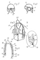
FIG. 1 shows a helmet from behind associated with a buckle strap of the restraint system,
FIG. 2 is a side view of said helmet located on a pilots head,
FIG. 3 is a front view of a pilots garment equipped with the helmet restraint system,
FIG. 4 shows the helmet restraint system of FIG. 3, the pilots garment omitted,
FIG. 5 is a partially cut out side view of an adjustment mechanism of said system and
FIG. 6 is a partially cut perspective view of a emergency release of the system.
DETAILED DESCRIPTION OF EMBODIMENTS OF THE INVENTION
A helmet restraint system 2 is configured for restraining the forward and downward movement of an occupant's helmet and head. Said restraint system is in particular adapted for a heavy pilot helmet 4 having an unfavorable centre of gravity, for example when provided with HMD and NVG. In FIGS. 1 and 2 the helmet 4 is shown associated with or hitched to a buckle strap 6 of the restraint system 2 by means of a first attachment means exemplified as a snap hook 8 permanently fastened to the central back part of the helmet 4.
FIG. 3 shows a front view of the restraint system integrated in a pilot's garment, e.g. a life vest, harness, a conventional flight jacket or an arm restraint jacket. In the illustrated embodiment the garment is a flight jacket 10 with a life vest having a buoyancy collar 12. The buckle strap 6 is configured to be movably disposed in pack cloth channels 14, 16 stitched to said flight jacket at the left front side and the right front side resp. of said jacket. A first end 18 of the buckle strap 6 is associated with an adjustment mechanism 20 as a first fixing point at the left front side of the jacket and the second end 22 is associated with an emergency release 23 as a second fixing point under its life vest at the right front side of the jacket. By means of said adjustment mechanism 20, which might be placed in a pocket fastened to the emergency radio pocket, the buckle strap 6 can be preloaded between its first end 18 and its second end 22 extended in a loop 24 coming out from a first 26 (left) and a second 28 (right) opening in the buoyancy collar of the jacket, said loop 24 being connected to said snap hook 8.
Advantageously, as best appear from FIG. 4, the buckle strap is partially made of elastic cord 30 and at least a part adjacent to its first end of inelastic cord 32. The elastic cord might be of a fairly elastic character suitable to generate an elastic resistance in the snap hook 8 tensed preferably within an interval of 10-300 N. For this purpose a regular shock absorber cord made of rubber would be preferred. The inelastic cord is preferably made of synthetic material like for instance spun yarn etc. capable to withstand a corresponding tension. The elastic 30 and inelastic 32 cords are interconnected by means of a seam 34, which means the cords might be stitched, melted or solded together.
In an advantageous embodiment, hollow rigid members, for example configured as a left 36 and right 38 tube of low friction plastic material as Teflon can be arranged in the resp. pack cloth channel 14, 16 between the first 26 and second 28 collar openings and the first 20 and second 23 fixing points respectively, for accommodating the buckle strap constituted of said elastic 30 and inelastic 32 cords. The ends of said pack cloth channels may consist of pockets closed by Velcro, which makes it easy to replace or detach the tubes 36, 38 if needed, e.g. when not flying with a HMG or NVG helmet. The tubes have a smooth transition in the ends to get a smooth sliding surface for the buckle strap 6.
FIG. 5 illustrates the adjustment mechanism (first fixing point) 20 in more detail. A house 40 made of suitable materials as delrin and aluminum is provided with a suitably compression spring 42 loaded slide 44, which locks inelastic cord 32 of the buckle strap 6 in the direction of the tension force F and allows said cord 32 to be displaced in the opposite direction. Hence, tension of the elastic cord 30 of the buckle strap 6 is effectuated by pulling its first end 18 (the free end said inelastic cord 32) in the opposite direction, which causes the slide 44 to compress the spring sufficiently to allow a desired tension of the elastic cord to generate an elastic resistance in the snap hook 8, preferably within an interval of 10-300 N.
  • When a desired tension has been established and the pulling is ended, by means of the spring load the slide 44 will wedge in the inelastic cord 32 against the wall in said house 40. When it is desired to decrease the elastic resistance in the snap hook 8, a slackening strap 46 is pulled, which is configured to urge the slide 44 against the force of said spring 42 and thereby relieve the tension in the buckle strap 6.
FIG. 6 illustrates the emergency release (second fixing point) 23 in more detail. A jamming cleat 48 of a conventional kind is sewn 50 to the pack cloth 52 at the second fixing point 23. The free end, i.e. the second end 22, of the elastic cord 30 of the buckle strap 6 is formed in a loop and jammed in said jamming cleat when the restraint system 2 is operative. In an event of an emergency situation the pilot can easily doff the helmet by simply pulling 54 the elastic cord 30 free from the jamming cleat and take off the helmet, the elastic cord will follow easily.
The helmet restraint system 2 is intended for widely variable G-loads in an interval from 1-9 G. Experiments have revealed that in order to get a neck muscle force as without helmet in neutral position during a load of 1 G, the elastic resistance in the snap hook typically would be tensed with 11 N. Further, in order to get a neck muscle force as without helmet in neutral position during a load of 9 G, the elastic resistance in the snap hook would typically be tensed with 268 N. Consequently, said restraint system 2 is easily adjustable during flight when changing between missions/maneuvers having different expected G-loads; easily adjustable even by exchanging type of aircraft (Hkp); rapidly adjustable during flight at a sudden alteration in G-load.
It is even possible to configure said restraint system 2 automatically adjustable in dependency of already present systems which respond to variations in G-load.

Claims (10)

1. A helmet restraint system for restraining forward and downward movement of a wearer's helmet and head, comprising:
a buckle strap having a first end and a second end and configured to be movably disposed in a garment of the wearer, the buckle strap being preloaded in said garment between the first end and the second end;
first attachment means engaged with said helmet and adapted for being associated with said buckle strap; said first attachment means comprising a snap hook with said buckle strap passing movably through said snap hook;
second attachment means engaged with the buckle strap, said second attachment means comprising a first fixing point at a left front side and a second fixing point at a right front side of said garment, wherein the first end of the buckle strap is attached to said first fixing point wherein the second end of the buckle strap is attached to said second fixing point, and wherein the buckle strap is extended in a loop coming out from a first opening and a second opening respectively in a collar of said garment for connection with said first attachment means.
2. The helmet restraint system according to claim 1, wherein the buckle strap comprises elastic cord and at least a portion of the buckle strap adjacent to the first end comprises inelastic cord.
3. The helmet restraint system according to claim 1, further comprising:
a seam interconnecting the elastic cord and the inelastic cord.
4. The helmet restraint system according to claim 1, further comprising:
hollow rigid members mounted in pack cloth channels and extending between the first collar opening and first fixing point and the second collar opening (28) and second fixing point (23) of the garment, wherein the buckle strap is at least partially guided in the hollow rigid members.
5. The helmet restraint system according to claim 1, further comprising:
an adjustment mechanism arranged at the first fixing point for adjusting the tension of the buckle strap at the first end.
6. The helmet restraint system according to claim 1, further comprising:
an emergency release arranged at the second fixing point for releasable fixation of the buckle strap at the second end.
7. The helmet restraint system according to claim 1, wherein the collar of the garment comprises a buoyancy collar of a life vest or flight jacket.
8. The helmet restraint system according to claim 7, wherein the collar comprises a buoyancy collar of a flight jacket and the flight jacket comprises an arm restraint jacket.
9. The helmet restraint system according to claim 1, wherein the garment comprises a harness.
10. The helmet restraint system according to claim 1, wherein the helmet restraint system is adapted for a heavy pilot helmet having an unfavorable center of gravity.
US11/700,097 2006-01-31 2007-01-31 Helmet restraint system Active 2030-03-27 US8046846B2 (en)

Applications Claiming Priority (3)

Application Number Priority Date Filing Date Title
EP06101090A EP1813528B1 (en) 2006-01-31 2006-01-31 Helmet restraint system
EP06101090.6 2006-01-31
EP06101090 2006-01-31

Publications (2)

Publication Number Publication Date
US20110093999A1 US20110093999A1 (en) 2011-04-28
US8046846B2 true US8046846B2 (en) 2011-11-01

Family

ID=37395841

Family Applications (1)

Application Number Title Priority Date Filing Date
US11/700,097 Active 2030-03-27 US8046846B2 (en) 2006-01-31 2007-01-31 Helmet restraint system

Country Status (5)

Country Link
US (1) US8046846B2 (en)
EP (1) EP1813528B1 (en)
AT (1) ATE410362T1 (en)
DE (1) DE602006003057D1 (en)
ES (1) ES2315994T3 (en)

Cited By (8)

* Cited by examiner, † Cited by third party
Publication number Priority date Publication date Assignee Title
US20100229290A1 (en) * 2007-03-20 2010-09-16 Xceed Holdings (Pty) Limited Adaptive head and neck restraint system for a vehicle occupant
US20110060260A1 (en) * 2009-09-10 2011-03-10 Drexel University Cervical spine protection apparatus and methods of use
US20140041103A1 (en) * 2011-04-19 2014-02-13 B.M.A. Buizza Mazzei Agency S.R.L. Balancing system for the head of a passenger of a vehicle, in particular a helicopter
US9586125B2 (en) 2012-10-30 2017-03-07 Mioflex, Llc Head and neck protection apparatus and methods
US9603404B2 (en) 2013-03-21 2017-03-28 Tim M. Pocatko Helmet system and safety device for use with a helmet
USD816791S1 (en) * 2015-02-04 2018-05-01 Intex Marketing Ltd. Inflatable swim device
US10016009B1 (en) 2013-09-06 2018-07-10 Colin Bacchus Hard hat safety line systems
US10524528B2 (en) * 2015-02-26 2020-01-07 B.M.A. Buizza Mazzei Agency S.R.L. System for supporting the head-helmet unit of a passenger inside a vehicle

Families Citing this family (3)

* Cited by examiner, † Cited by third party
Publication number Priority date Publication date Assignee Title
GR20100100591A (en) * 2010-10-13 2012-05-18 Παυλος Δημητριου Γιαννακοπουλος Pretensioners with bowden cables and ejection seat equipped with these.
US20140247129A1 (en) 2013-03-01 2014-09-04 Ricardo Lewis de la Fuente Impact awareness device
US10729201B1 (en) 2013-03-01 2020-08-04 Rlf Industries Llc Impact protection apparatus

Citations (11)

* Cited by examiner, † Cited by third party
Publication number Priority date Publication date Assignee Title
US3157885A (en) * 1961-03-14 1964-11-24 Ml Aviation Co Ltd Automatically pressurized flying suit
US3925822A (en) * 1974-06-18 1975-12-16 John H Sawyer Safety harness for a helmet
US5259833A (en) * 1992-09-15 1993-11-09 Barnett Larry W Back bending motion limiting apparatus
US5272770A (en) 1992-11-16 1993-12-28 Allen Richard K Head restraining system
US5437613A (en) 1993-08-23 1995-08-01 Reggio; David Neck brace
US5692933A (en) * 1995-09-14 1997-12-02 Simula Inc. Low profile flotation collar
US6006700A (en) * 1996-09-24 1999-12-28 Dalloz Safety, Inc. Safety harness
US6330722B1 (en) 2001-01-09 2001-12-18 Mcy Iii Trust Protective helmet restraint and head and neck stabilizing system
US20030146348A1 (en) * 2001-06-14 2003-08-07 Douglas David Jay Integrated parachute harness system
US20040055077A1 (en) 2002-09-23 2004-03-25 Wright Jay Michael Wright device
US6810535B1 (en) 2002-06-19 2004-11-02 Speed Solutions, Inc. Helmet restraint system

Patent Citations (11)

* Cited by examiner, † Cited by third party
Publication number Priority date Publication date Assignee Title
US3157885A (en) * 1961-03-14 1964-11-24 Ml Aviation Co Ltd Automatically pressurized flying suit
US3925822A (en) * 1974-06-18 1975-12-16 John H Sawyer Safety harness for a helmet
US5259833A (en) * 1992-09-15 1993-11-09 Barnett Larry W Back bending motion limiting apparatus
US5272770A (en) 1992-11-16 1993-12-28 Allen Richard K Head restraining system
US5437613A (en) 1993-08-23 1995-08-01 Reggio; David Neck brace
US5692933A (en) * 1995-09-14 1997-12-02 Simula Inc. Low profile flotation collar
US6006700A (en) * 1996-09-24 1999-12-28 Dalloz Safety, Inc. Safety harness
US6330722B1 (en) 2001-01-09 2001-12-18 Mcy Iii Trust Protective helmet restraint and head and neck stabilizing system
US20030146348A1 (en) * 2001-06-14 2003-08-07 Douglas David Jay Integrated parachute harness system
US6810535B1 (en) 2002-06-19 2004-11-02 Speed Solutions, Inc. Helmet restraint system
US20040055077A1 (en) 2002-09-23 2004-03-25 Wright Jay Michael Wright device

Non-Patent Citations (1)

* Cited by examiner, † Cited by third party
Title
European Search Report.

Cited By (15)

* Cited by examiner, † Cited by third party
Publication number Priority date Publication date Assignee Title
US20100229290A1 (en) * 2007-03-20 2010-09-16 Xceed Holdings (Pty) Limited Adaptive head and neck restraint system for a vehicle occupant
US8990962B2 (en) 2009-09-10 2015-03-31 Drexel University Cervical spine protection apparatus and methods of use
US9492306B2 (en) 2009-09-10 2016-11-15 Drexel University Cervical spine protection apparatus and methods of use
US8528113B2 (en) * 2009-09-10 2013-09-10 Drexal University Cervical spine protection apparatus and methods of use
US8341770B2 (en) * 2009-09-10 2013-01-01 Drexel University Cervical spine protection apparatus and methods of use
US8683612B2 (en) 2009-09-10 2014-04-01 Drexel University Cervical spine protection apparatus and methods of use
US20110060260A1 (en) * 2009-09-10 2011-03-10 Drexel University Cervical spine protection apparatus and methods of use
US9265296B2 (en) * 2011-04-19 2016-02-23 B.M.A. Buizza Mazzei Agency S.R.L. Balancing system for the head of a passenger of a vehicle, in particular a helicopter
US20140041103A1 (en) * 2011-04-19 2014-02-13 B.M.A. Buizza Mazzei Agency S.R.L. Balancing system for the head of a passenger of a vehicle, in particular a helicopter
US9586125B2 (en) 2012-10-30 2017-03-07 Mioflex, Llc Head and neck protection apparatus and methods
US9603404B2 (en) 2013-03-21 2017-03-28 Tim M. Pocatko Helmet system and safety device for use with a helmet
USRE48718E1 (en) 2013-03-21 2021-09-07 J. Nolan Group LLC Helmet system and safety device for use with a helmet
US10016009B1 (en) 2013-09-06 2018-07-10 Colin Bacchus Hard hat safety line systems
USD816791S1 (en) * 2015-02-04 2018-05-01 Intex Marketing Ltd. Inflatable swim device
US10524528B2 (en) * 2015-02-26 2020-01-07 B.M.A. Buizza Mazzei Agency S.R.L. System for supporting the head-helmet unit of a passenger inside a vehicle

Also Published As

Publication number Publication date
DE602006003057D1 (en) 2008-11-20
US20110093999A1 (en) 2011-04-28
EP1813528A1 (en) 2007-08-01
ATE410362T1 (en) 2008-10-15
EP1813528B1 (en) 2008-10-08
ES2315994T3 (en) 2009-04-01

Similar Documents

Publication Publication Date Title
US8046846B2 (en) Helmet restraint system
US4477041A (en) Head and neck restraint system
US6367882B1 (en) Slip-retarding upper torso restraint harness and system
US6810535B1 (en) Helmet restraint system
AU2007223700B2 (en) Child restraint device with energy absorbing regions
US6813782B2 (en) Safety device and system for head and neck stabilization
US8393017B2 (en) Apparatus to be worn on an individual's chest below a full face helmet to limit the occurrence of cervical spinal cord injuries in the event of a crash
US7155747B2 (en) Head stabilizing system
US20010002087A1 (en) Helmet restraint system and method
JP5053280B2 (en) Head and neck restraint system and device
EP2139728B1 (en) Adaptive head and neck restraint system for a person in a vehicle
US10178888B2 (en) Head restraint system having a rate sensitive device
US10391898B1 (en) Torso equipment support system (TESS)
EP2222197B1 (en) Head and neck support device
US20020178492A1 (en) Race car driver helmet/head restraint
EP3345784A1 (en) Child car seat
US6871360B1 (en) Head restraint device for use with a high performance vehicle
US4938436A (en) Safety harness and belt assemblies for aircraft crewmembers
EP2760742B1 (en) Parachute harness container with bio-contoured load distributing vest
US11433840B2 (en) Head and neck support and protection device
US5033697A (en) Pilot head support apparatus
US8162259B2 (en) Aircraft ejection seat with passive limb retention
WO2022175881A1 (en) Passive safety device
Steele-Perkins Recent improvements in crash restraint in UK helicopters
PATTERSON Helmet-mounted head restraint(Patent)

Legal Events

Date Code Title Description
AS Assignment

Owner name: SAAB AB, SWEDEN

Free format text: ASSIGNMENT OF ASSIGNORS INTEREST;ASSIGNORS:KARLSSON, JIMMIE;MARTIKKALA, MARIA;SIGNING DATES FROM 20070123 TO 20070125;REEL/FRAME:019305/0533

FEPP Fee payment procedure

Free format text: PAYOR NUMBER ASSIGNED (ORIGINAL EVENT CODE: ASPN); ENTITY STATUS OF PATENT OWNER: LARGE ENTITY

STCF Information on status: patent grant

Free format text: PATENTED CASE

FPAY Fee payment

Year of fee payment: 4

MAFP Maintenance fee payment

Free format text: PAYMENT OF MAINTENANCE FEE, 8TH YEAR, LARGE ENTITY (ORIGINAL EVENT CODE: M1552); ENTITY STATUS OF PATENT OWNER: LARGE ENTITY

Year of fee payment: 8

MAFP Maintenance fee payment

Free format text: PAYMENT OF MAINTENANCE FEE, 12TH YEAR, LARGE ENTITY (ORIGINAL EVENT CODE: M1553); ENTITY STATUS OF PATENT OWNER: LARGE ENTITY

Year of fee payment: 12