EP3498519A1 - Train current collecting device - Google Patents
Train current collecting device Download PDFInfo
- Publication number
- EP3498519A1 EP3498519A1 EP17857852.2A EP17857852A EP3498519A1 EP 3498519 A1 EP3498519 A1 EP 3498519A1 EP 17857852 A EP17857852 A EP 17857852A EP 3498519 A1 EP3498519 A1 EP 3498519A1
- Authority
- EP
- European Patent Office
- Prior art keywords
- arm
- reflux
- collector
- shoe
- current
- Prior art date
- Legal status (The legal status is an assumption and is not a legal conclusion. Google has not performed a legal analysis and makes no representation as to the accuracy of the status listed.)
- Granted
Links
Images

Classifications
-
- B—PERFORMING OPERATIONS; TRANSPORTING
- B60—VEHICLES IN GENERAL
- B60L—PROPULSION OF ELECTRICALLY-PROPELLED VEHICLES; SUPPLYING ELECTRIC POWER FOR AUXILIARY EQUIPMENT OF ELECTRICALLY-PROPELLED VEHICLES; ELECTRODYNAMIC BRAKE SYSTEMS FOR VEHICLES IN GENERAL; MAGNETIC SUSPENSION OR LEVITATION FOR VEHICLES; MONITORING OPERATING VARIABLES OF ELECTRICALLY-PROPELLED VEHICLES; ELECTRIC SAFETY DEVICES FOR ELECTRICALLY-PROPELLED VEHICLES
- B60L5/00—Current collectors for power supply lines of electrically-propelled vehicles
- B60L5/04—Current collectors for power supply lines of electrically-propelled vehicles using rollers or sliding shoes in contact with trolley wire
-
- B—PERFORMING OPERATIONS; TRANSPORTING
- B60—VEHICLES IN GENERAL
- B60L—PROPULSION OF ELECTRICALLY-PROPELLED VEHICLES; SUPPLYING ELECTRIC POWER FOR AUXILIARY EQUIPMENT OF ELECTRICALLY-PROPELLED VEHICLES; ELECTRODYNAMIC BRAKE SYSTEMS FOR VEHICLES IN GENERAL; MAGNETIC SUSPENSION OR LEVITATION FOR VEHICLES; MONITORING OPERATING VARIABLES OF ELECTRICALLY-PROPELLED VEHICLES; ELECTRIC SAFETY DEVICES FOR ELECTRICALLY-PROPELLED VEHICLES
- B60L5/00—Current collectors for power supply lines of electrically-propelled vehicles
- B60L5/38—Current collectors for power supply lines of electrically-propelled vehicles for collecting current from conductor rails
- B60L5/39—Current collectors for power supply lines of electrically-propelled vehicles for collecting current from conductor rails from third rail
-
- B—PERFORMING OPERATIONS; TRANSPORTING
- B60—VEHICLES IN GENERAL
- B60L—PROPULSION OF ELECTRICALLY-PROPELLED VEHICLES; SUPPLYING ELECTRIC POWER FOR AUXILIARY EQUIPMENT OF ELECTRICALLY-PROPELLED VEHICLES; ELECTRODYNAMIC BRAKE SYSTEMS FOR VEHICLES IN GENERAL; MAGNETIC SUSPENSION OR LEVITATION FOR VEHICLES; MONITORING OPERATING VARIABLES OF ELECTRICALLY-PROPELLED VEHICLES; ELECTRIC SAFETY DEVICES FOR ELECTRICALLY-PROPELLED VEHICLES
- B60L5/00—Current collectors for power supply lines of electrically-propelled vehicles
- B60L5/40—Current collectors for power supply lines of electrically-propelled vehicles for collecting current from lines in slotted conduits
Definitions
- the present invention relates to the railway train power supply field, particularly to a double-pole current collecting structure and a current collecting technique.
- Electric trains employ a pantograph-catenary contact current collection (receiving) scheme, in which the catenary may be divided into flexible catenary and rigid catenary.
- Electric railways usually employ the pantograph-flexible catenary contact scheme, while urban railways employ the pantograph-flexible catenary contact scheme besides the pantograph-rigid catenary contact scheme.
- the flexible catenary system belongs to a flexible system, while the third rail contact system and the rigid catenary system are rigid systems.
- Flexible systems usually bear tension besides the contact pressure of pantograph, while rigid systems only bear contact pressure but hardly bear tension.
- rigid systems Compared with flexible systems, rigid systems have obvious advantages such as simple structure, high current capacity, high reliability and high durability, etc.
- rigid system involve problems related with structural form, suspension method, span length and dynamic performance matching with pantograph (collector shoe); in addition, the movement of the train in operation is transmitted directly to the catenary or the third rail via the pantograph or collector shoe, and affects the performance of contact current collection between the pantograph and the catenary or between the collector shoe and the third rail.
- pantograph collector shoe
- the influences of those factors are especially severe when the train is running at a high speed, and consequently seriously limit the play of the advantages of rigid systems.
- the current pantograph-catenary or collector shoe-third rail contact current collection method used by electrified railways and urban railways belongs to a monopole contact current collection method.
- the present application proposes a double-pole contact current collection structure, which can eliminate the adverse effects on the current collection system incurred by lateral and vertical vibrations of the train during operation, maintain in a good contact condition, and give better play to the advantages of a rigid system, and is applicable to high-speed railway applications.
- the object of the present invention is to provide a current collecting device for a train, which can effectively eliminate the influence on contact-type current collection on the train incurred by lateral and vertical vibrations of the train, maintain the contact area between a collector shoe and a power supply rail and the contact area between a reflux shoe and a reflux rail at a constant value, so as to exert the advantages of a rigid system better.
- the current collecting device for a train is applicable to high-speed railway applications.
- a current collecting device for a train comprising a collector arm and a current reflux arm connected with a bogie, a crossbeam is provided in the middle between the ends of the bogie of the train, two sets of bearing seats are provided below the crossbeam, the top end of the collector arm and the top end of the current reflux arm are hingedly connected with the bearing seats respectively via a rotating shaft arranged in parallel to the longitudinal direction of the train; an inverted t-shaped limiter is provided between the two sets of bearing seats, a top part of the limiter is fixed to a middle part of the bottom of the crossbeam, a bottom part of the limiter is overhung between the collector arm and the current reflux arm, with clearance at both sides of the limiter; two ends of a booster spring are fixed to the middle part of the collector arm and the middle part of the current reflux arm respectively; a fixed end of the collector shoe is hingedly connected with the bottom end of the collector arm, a free end of the collector shoe is in
- the collector arm, the current reflux arm, and the limiter are made of an insulating material respectively.
- the collector shoe and the reflux shoe are made of a wear-resistant conducting material respectively.
- the free end of the collector shoe is made in a concave semicircular shape and the side of the power supply rail in contact with the collector shoe is made in a convex semicircular shape, or the free end of the reflux shoe is made in a concave semicircular shape and the side of the reflux rail in contact with the reflux shoe is made in a convex semicircular shape.
- the booster spring is configured to generate contact pressure of the collector arm on the power supply rail and contact pressure of the current reflux arm on the reflux rail; the magnitude of the contact pressure may be calculated according to a model, and is usually 70-100N based on the experience.
- the limiter is configured to limit the degree of closeness between the collector arm and the current reflux arm.
- the size of the clearance between two sides of the bottom part of the limiter and the collector arm/current reflux arm depends on the following factors: (1) specific position and size of the bottom part of the limiter and maximum amplitude of lateral vibration of the train; (2) requirement for insulation between the collector shoe and the reflux shoe after interruption of the power supply rail and the reflux rail when the train passes through a railway switch.
- pads such as rubber pads or sponge pads may be provided at possible contact parts of the limiter.
- the deflection angle of the collector shoe and the reflux shoe limited by the limiting plate at the bottom end of the collector arm and the current reflux arm may be ascertained through calculation from the maximum amplitude of lateral and vertical vibrations of the train, the length of the collector arm (current reflux arm), and the length of the collector shoe (reflux shoe).
- the collector shoe and the reflux shoe supply power to the traction drive system of the train through cables respectively.
- the collector arm and the current reflux arm shall have through-holes, through which the cables can pass and are connected to the power supply system in the train.
- the working principle of the present invention is as follows: the top end of the collector arm and the top end of the current reflux arm are hung from the bottom of the crossbeam arranged on the bogie of the train via the rotating shaft, the collector arm and the current reflux arm are in a pendulum form with respect to the transverse direction of the train; besides, the collector arm is hingedly connected with the collector shoe, the current reflux arm is hingedly connected with the reflux shoe, and the collector shoe and the reflux shoe can deflect in the vertical direction within a certain range, so that the lateral and vertical vibration forces of the train can't act on the power supply rail via the collector arm and the collector shoe respectively, and can't act on the reflux rail via the current reflux arm and the reflux shoe as well; thus, decoupling is realized and the adverse effect incurred by lateral and vertical vibrations of the train on the performance of contact-type current collection between the collector shoe and the power supply rail and between the reflux shoe and the reflux rail is eliminated, the contact area between the collector shoe and the power supply rail and the contact area between the reflux
- the present invention attains the following beneficial effects:
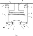
- Fig. 1 shows an embodiment of the present invention: a current collecting device for a train, comprising a collector arm 1 and a current reflux arm 2 connected with a bogie, wherein, a crossbeam 9 is provided in the middle between the ends of the bogie of the train, two sets of bearing seats 8 are provided below the crossbeam 9, the top end of the collector arm 1 and the top end of the current reflux arm 2 are hinged with the bearing seats 8 respectively via rotating shafts 7 arranged in parallel to the longitudinal direction of the train; an inverted t-shaped limiter 5 is provided between the two sets of bearing seats 8, a top part of the limiter 5 is fixed to a middle part of the bottom of the crossbeam 9, a bottom part of the limiter 5 is overhung between the collector arm 1 and the current reflux arm 2, with clearance at both sides of the limiter 5; two ends of a booster spring 6 are fixed to the middle part of the collector arm 1 and the middle part of the current reflux arm 2 respectively; a fixed end of the collector shoe 3 is hinged with the bottom end of the
- the collector arm 1 and the current reflux arm 2 are made of an insulating material respectively.
- the collector shoe 3 and the reflux shoe 4 are made of wear-resistant conducting material respectively.
- the power supply rail 10 and the reflux rail 11 are mounted and fix to insulating base 13.
- the collector arm 1 When the train is stopped in a straight section, the collector arm 1 is parallel to the current reflux arm 2; the collector shoe 3 is perpendicular to the collector arm 1, and the reflux shoe 4 is perpendicular to the current reflux arm 2.
- Fig. 1 is a front view.
- the structure shown in Fig. 1 is in bilateral symmetry.
- the center line of the structure intersects with the center point between two rails when the train is stopped in a straight section.
- the current collecting device for a train is applicable to urban railways and high-speed railways that employ a monolithic track bed; the collector shoe 3, the reflux shoe 4, the collector arm 1, the current reflux arm 2, and the crossbeam 9 form a quadrangle; the quadrangle is deformed as the train vibrates in the lateral direction or vertical direction, wherein, the clearance between the collector shoe 3 and the reflux shoe 4 and the insulating base 13 can meet the inclination requirement for the collector shoe 3 and the reflux shoe 4.
- the limiting plates 12 are configured to limit the deflection of the collector shoe and the reflux shoe in the vertical direction.
- Fig. 2 is a left view of the structure in the present invention, and mainly depicts the collector arm 1, which is in a wasp waist shape.
- the top end of the collector arm 1 is hinged with the bearing seat 8 via the rotating shaft 7 arranged in parallel to the longitudinal direction of the train, is overhung below the crossbeam 9, and has a structure with enlarged top width to improve stress bearing capacity; the width of the bottom end of the collector arm 1 is enlarged to facilitate hinged connection with the collector shoe 3.
- the collector shoe 3 has higher current capacity and greater sectional area.
- the current reflux arm 2 is in the same structure and shape as the collector arm 1.
Landscapes
- Engineering & Computer Science (AREA)
- Power Engineering (AREA)
- Transportation (AREA)
- Mechanical Engineering (AREA)
- Current-Collector Devices For Electrically Propelled Vehicles (AREA)
Abstract
Description
- The present invention relates to the railway train power supply field, particularly to a double-pole current collecting structure and a current collecting technique.
- Electric trains employ a pantograph-catenary contact current collection (receiving) scheme, in which the catenary may be divided into flexible catenary and rigid catenary. Electric railways usually employ the pantograph-flexible catenary contact scheme, while urban railways employ the pantograph-flexible catenary contact scheme besides the pantograph-rigid catenary contact scheme. In addition, there is a collector shoe-third rail contact current collection scheme. As the name implies, the flexible catenary system belongs to a flexible system, while the third rail contact system and the rigid catenary system are rigid systems. Flexible systems usually bear tension besides the contact pressure of pantograph, while rigid systems only bear contact pressure but hardly bear tension. Compared with flexible systems, rigid systems have obvious advantages such as simple structure, high current capacity, high reliability and high durability, etc. However, rigid system involve problems related with structural form, suspension method, span length and dynamic performance matching with pantograph (collector shoe); in addition, the movement of the train in operation is transmitted directly to the catenary or the third rail via the pantograph or collector shoe, and affects the performance of contact current collection between the pantograph and the catenary or between the collector shoe and the third rail. Moreover, the influences of those factors are especially severe when the train is running at a high speed, and consequently seriously limit the play of the advantages of rigid systems. As a result, it is still difficult for rigid systems to adapt to high-speed railways up to now.
- In addition, the current pantograph-catenary or collector shoe-third rail contact current collection method used by electrified railways and urban railways belongs to a monopole contact current collection method.
- The applicant proposed "Power Supply Structure for Rail Transit (Chinese Application No.
201610213944.6 - The object of the present invention is to provide a current collecting device for a train, which can effectively eliminate the influence on contact-type current collection on the train incurred by lateral and vertical vibrations of the train, maintain the contact area between a collector shoe and a power supply rail and the contact area between a reflux shoe and a reflux rail at a constant value, so as to exert the advantages of a rigid system better. The current collecting device for a train is applicable to high-speed railway applications.
- The object of the present invention is attained with the following technical scheme: a current collecting device for a train, comprising a collector arm and a current reflux arm connected with a bogie, a crossbeam is provided in the middle between the ends of the bogie of the train, two sets of bearing seats are provided below the crossbeam, the top end of the collector arm and the top end of the current reflux arm are hingedly connected with the bearing seats respectively via a rotating shaft arranged in parallel to the longitudinal direction of the train; an inverted t-shaped limiter is provided between the two sets of bearing seats, a top part of the limiter is fixed to a middle part of the bottom of the crossbeam, a bottom part of the limiter is overhung between the collector arm and the current reflux arm, with clearance at both sides of the limiter; two ends of a booster spring are fixed to the middle part of the collector arm and the middle part of the current reflux arm respectively; a fixed end of the collector shoe is hingedly connected with the bottom end of the collector arm, a free end of the collector shoe is in a convex semicircular shape and arranged in contact with a concave semicircular side of a power supply rail; a fixed end of the reflux shoe is hingedly connected with the bottom end of the current reflux arm, a free end of the reflux shoe is in a convex semicircular shape and arranged in contact with a concave semicircular side of a reflux rail; the bottom end of the collector arm and the bottom end of the current reflux arm are provided with limiting plates respectively, and the center lines of the limiting plates are perpendicular to a center line of the collector arm and a center line of the current reflux arm respectively.
- The collector arm, the current reflux arm, and the limiter are made of an insulating material respectively.
- The collector shoe and the reflux shoe are made of a wear-resistant conducting material respectively.
- The same satisfactory contact effect can be attained if the free end of the collector shoe is made in a concave semicircular shape and the side of the power supply rail in contact with the collector shoe is made in a convex semicircular shape, or the free end of the reflux shoe is made in a concave semicircular shape and the side of the reflux rail in contact with the reflux shoe is made in a convex semicircular shape.
- The booster spring is configured to generate contact pressure of the collector arm on the power supply rail and contact pressure of the current reflux arm on the reflux rail; the magnitude of the contact pressure may be calculated according to a model, and is usually 70-100N based on the experience.
- The limiter is configured to limit the degree of closeness between the collector arm and the current reflux arm. The size of the clearance between two sides of the bottom part of the limiter and the collector arm/current reflux arm depends on the following factors: (1) specific position and size of the bottom part of the limiter and maximum amplitude of lateral vibration of the train; (2) requirement for insulation between the collector shoe and the reflux shoe after interruption of the power supply rail and the reflux rail when the train passes through a railway switch. To avoid collision and wearing between the two sides of the bottom part of the limiter and the collector arm/current reflux arm when the train passes through a railway switch, pads such as rubber pads or sponge pads may be provided at possible contact parts of the limiter.
- The deflection angle of the collector shoe and the reflux shoe limited by the limiting plate at the bottom end of the collector arm and the current reflux arm may be ascertained through calculation from the maximum amplitude of lateral and vertical vibrations of the train, the length of the collector arm (current reflux arm), and the length of the collector shoe (reflux shoe).
- The collector shoe and the reflux shoe supply power to the traction drive system of the train through cables respectively. To reduce external interference and meet high-speed aerodynamic requirements, the collector arm and the current reflux arm shall have through-holes, through which the cables can pass and are connected to the power supply system in the train.
- The working principle of the present invention is as follows: the top end of the collector arm and the top end of the current reflux arm are hung from the bottom of the crossbeam arranged on the bogie of the train via the rotating shaft, the collector arm and the current reflux arm are in a pendulum form with respect to the transverse direction of the train; besides, the collector arm is hingedly connected with the collector shoe, the current reflux arm is hingedly connected with the reflux shoe, and the collector shoe and the reflux shoe can deflect in the vertical direction within a certain range, so that the lateral and vertical vibration forces of the train can't act on the power supply rail via the collector arm and the collector shoe respectively, and can't act on the reflux rail via the current reflux arm and the reflux shoe as well; thus, decoupling is realized and the adverse effect incurred by lateral and vertical vibrations of the train on the performance of contact-type current collection between the collector shoe and the power supply rail and between the reflux shoe and the reflux rail is eliminated, the contact area between the collector shoe and the power supply rail and the contact area between the reflux shoe and the reflux rail are maintained at a constant value, and thereby high current collection performance is maintained during the operation of the train.
- Compared with the prior art, the present invention attains the following beneficial effects:
- 1. In the present invention, the top end of the collector arm and the top end of the current reflux arm are hinged with the bearing seats while the bottom end of the collector arm and the bottom end of the current reflux arm are hinged with the collector shoe and the reflux shoe respectively, so that the adverse effect incurred by lateral and vertical vibrations of the train in operation on the performance of the contact-type current collection between the collector shoe and the power supply rail and between the reflux shoe and the reflux rail can be eliminated, the contact area between the collector shoe and the power supply rail and the contact area between the reflux shoe and the reflux rail are maintained at a constant value, and thereby high contact current collection performance is maintained during the operation of the train.
- 2. The current collecting device provided in present invention is suitable for a rigid system fixedly mounted along an insulating base; with the device provided in the present invention, the dynamic performance of the rigid system is not limited by the original suspension structure and span anymore. The present invention is applicable to high-speed railway applications.
- 3. The collecting device provided in the present invention employs advanced techniques, has outstanding performance, and is easy to implement.
- The accompanying drawings are provided to facilitate further understanding of the present invention and constitute a part of the patent application; the embodiments and associated description provided in the present invention are provided to interpret the present invention, and shall not be deemed as constituting any undue limitation to the present invention. In the figures:
-
Fig.1 is a schematic structural diagram of an embodiment of the present invention; -
Fig. 2 is a schematic diagram of an embodiment of the present invention. - Hereunder the present invention will be further detailed in embodiments, with reference to the accompanying drawings.
-
Fig. 1 shows an embodiment of the present invention: a current collecting device for a train, comprising acollector arm 1 and acurrent reflux arm 2 connected with a bogie, wherein, acrossbeam 9 is provided in the middle between the ends of the bogie of the train, two sets ofbearing seats 8 are provided below thecrossbeam 9, the top end of thecollector arm 1 and the top end of thecurrent reflux arm 2 are hinged with thebearing seats 8 respectively via rotatingshafts 7 arranged in parallel to the longitudinal direction of the train; an inverted t-shaped limiter 5 is provided between the two sets ofbearing seats 8, a top part of thelimiter 5 is fixed to a middle part of the bottom of thecrossbeam 9, a bottom part of thelimiter 5 is overhung between thecollector arm 1 and thecurrent reflux arm 2, with clearance at both sides of thelimiter 5; two ends of a booster spring 6 are fixed to the middle part of thecollector arm 1 and the middle part of thecurrent reflux arm 2 respectively; a fixed end of thecollector shoe 3 is hinged with the bottom end of thecollector arm 1, a free end of thecollector shoe 3 is in a convex semicircular shape and arranged in contact with a concave semicircular side of apower supply rail 10; a fixed end of the reflux shoe 4 is hinged with the bottom end of thecurrent reflux arm 2, a free end of the reflux shoe 4 is in a convex semicircular shape and arranged in contact with a concave semicircular side of areflux rail 11; the bottom end of thecollector arm 1 and the bottom end of thecurrent reflux arm 2 are both provided with alimiting plate 12; when the train is stopped in a straight section the horizontal center lines of the limiting plates 12 (i.e., the horizontal center line of thecollector shoe 3 or the reflux shoe 4 when the train is stopped in a straight section) is perpendicular to a vertical center line of thecollector arm 1 and a vertical center line of thecurrent reflux arm 2 respectively. - The
collector arm 1 and thecurrent reflux arm 2 are made of an insulating material respectively. - The
collector shoe 3 and the reflux shoe 4 are made of wear-resistant conducting material respectively. - The
power supply rail 10 and thereflux rail 11 are mounted and fix to insulatingbase 13. - When the train is stopped in a straight section, the
collector arm 1 is parallel to thecurrent reflux arm 2; thecollector shoe 3 is perpendicular to thecollector arm 1, and the reflux shoe 4 is perpendicular to thecurrent reflux arm 2. -
Fig. 1 is a front view. The structure shown inFig. 1 is in bilateral symmetry. The center line of the structure intersects with the center point between two rails when the train is stopped in a straight section. - The current collecting device for a train is applicable to urban railways and high-speed railways that employ a monolithic track bed; the
collector shoe 3, the reflux shoe 4, thecollector arm 1, thecurrent reflux arm 2, and thecrossbeam 9 form a quadrangle; the quadrangle is deformed as the train vibrates in the lateral direction or vertical direction, wherein, the clearance between thecollector shoe 3 and the reflux shoe 4 and theinsulating base 13 can meet the inclination requirement for thecollector shoe 3 and the reflux shoe 4. Thelimiting plates 12 are configured to limit the deflection of the collector shoe and the reflux shoe in the vertical direction. -
Fig. 2 is a left view of the structure in the present invention, and mainly depicts thecollector arm 1, which is in a wasp waist shape. The top end of thecollector arm 1 is hinged with thebearing seat 8 via the rotatingshaft 7 arranged in parallel to the longitudinal direction of the train, is overhung below thecrossbeam 9, and has a structure with enlarged top width to improve stress bearing capacity; the width of the bottom end of thecollector arm 1 is enlarged to facilitate hinged connection with thecollector shoe 3. Usually, thecollector shoe 3 has higher current capacity and greater sectional area. Thecurrent reflux arm 2 is in the same structure and shape as thecollector arm 1.
Claims (11)
- A current collecting device for a train, comprising a collector arm (1) and a current reflux arm (2) connected with a bogie, characterised in that, the current collecting device for a train further comprises:two sets of bearing seats (8) provided on the bogie;wherein the top end of the collector arm (1) is hinged with one of the two sets of bearing seats (8), and the top end of the current reflux arm (2) is hinged with the other one of the two sets of bearing seats (8);a collector shoe (3);a reflux shoe (4);wherein a fixed end of the collector shoe (3) is hinged with the bottom end of the collector arm (1), a free end of the collector shoe (3) is arranged in contact with a power supply rail (10), a fixed end of the reflux shoe (4) is hinged with the bottom end of the reflux arm (2), and a free end of the reflux shoe (4) is arranged in contact with a reflux rail (11);a booster spring (6);wherein one end of the booster spring (6) is connected with the collector arm (1), and the other end of the booster spring (6) is connected with the reflux arm (2).
- The current collecting device for a train according to claim 1, characterised in that, the current collecting device for a train further comprising a crossbeam (9) disposed in the middle between the ends of the bogie, the two sets of bearing seats (8) are disposed below the crossbeam (9).
- The current collecting device for a train according to claim 1, characterised in that, the current collecting device for a train further comprising a limiter (5), a top part of the limiter (5) is located between the two sets of bearing seats (8), a bottom part of the limiter (5) is overhung between the collector arm (1) and the current reflux arm (2), with a clearance between the bottom part of the limiter (5) and the collector arm (1) and a clearance between the bottom part of the limiter (5) and the current reflux arm (2).
- The current collecting device for a train according to claim 2, characterised in that, the current collecting device for a train further comprising a limiter (5) connected with the crossbeam (9), the top part of the limiter (5) is fixed to a middle part of the bottom of the crossbeam (9), the bottom part of the limiter (5) is overhung between the collector arm (1) and the current reflux arm (2) with clearance at both sides of the bottom part.
- The current collecting device for a train according to any one of claims 1-4, characterised in that, one end of the booster spring (6) is arranged on a middle part of the collector arm (1), and the other end of the booster spring (6) is arranged on a middle part of the reflux arm (2).
- The current collecting device for a train according to any one of claims 1-4, characterised in that, the free end of the collector shoe (3) is in a convex semicircular shape and is in contact with a concave semicircular side of the power supply rail (10); the free end of the reflux shoe (4) is in a convex semicircular shape and is in contact with a concave semicircular side of the reflux rail (11);
or, the free end of the collector shoe (3) is in a concave semicircular shape and is in contact with a convex semicircular side of the power supply rail (10); the free end of the reflux shoe (4) is in a concave semicircular shape and is in contact with a convex semicircular side of the reflux rail (11). - The current collecting device for a train according to any one of claims 1-4, characterised in that, the bottom end of the collector arm (1) and the bottom end of the current reflux arm (2) are both provided with a limiting plate (12), and the horizontal center lines of the limiting plates (12) are perpendicular to the vertical center line of the collector arm (1) and the vertical center line of the current reflux arm (2) respectively.
- The current collecting device for a train according to any one of claims 1-4, characterised in that, the current collecting device for a train further comprising two rotating shafts (7) arranged in parallel to the longitudinal direction of the train, the top end of the collector arm (1) is hinged with one of the two sets of bearing seats (8) via one of the two rotating shafts (7), and the top end of the current reflux arm (2) is hinged with the other one of the two sets of bearing seats (8) via the other one of the two pivots (7).
- A current collecting device for a train, comprising a collector arm (1) and a current reflux arm (2) connected with a bogie, characterised in that, a crossbeam (9) is provided in the middle between the ends of the bogie of the train, two sets of bearing seats (8) are provided below the crossbeam (9), the top end of the collector arm (1) and the top end of the current reflux arm (2) are hinged with the bearing seats (8) via a rotating shaft (7) arranged in parallel to the longitudinal direction of the train respectively; an inverted t-shaped limiter (5) is provided between the two sets of bearing seats (8), a top part of the limiter (5) is fixed to a middle part of the bottom of the crossbeam (9), a bottom part of the limiter (5) is overhung between the collector arm (1) and the current reflux arm (2) with clearance at both sides of the limiter (5); two ends of a booster spring (6) are fixed to the middle part of the collector arm (1) and the middle part of the current reflux arm (2) respectively; a fixed end of the collector shoe (3) is hinged with the bottom end of the collector arm (1), a free end of the collector shoe (3) is in a convex semicircular shape and arranged in contact with a concave semicircular side of a power supply rail (10); a fixed end of the reflux shoe (4) is hinged with the bottom end of the current reflux arm (2), a free end of the reflux shoe (4) is in a convex semicircular shape and arranged in contact with a concave semicircular side of a reflux rail (11); the bottom end of the collector arm (1) and the bottom end of the current reflux arm (2) are both provided with a limiting plate (12) respectively, and the center lines of the limiting plates (12) are perpendicular to the center line of the collector arm (1) and the center line of the current reflux arm (2) respectively.
- The current collecting device for a train according to claim 9, characterised in that, the collector arm (1), the current reflux arm (2), and the limiter (5) are made of insulating material respectively.
- The current collecting device for a train according to claim 9, characterised in that, the collector shoe (3) and the reflux shoe (4) are made of wear-resistant conducting material respectively.
Applications Claiming Priority (2)
| Application Number | Priority Date | Filing Date | Title |
|---|---|---|---|
| CN201610880589.8A CN106379176B (en) | 2016-10-09 | 2016-10-09 | A kind of train current collecting equipment |
| PCT/CN2017/105086 WO2018064971A1 (en) | 2016-10-09 | 2017-09-30 | Train current collecting device |
Publications (3)
| Publication Number | Publication Date |
|---|---|
| EP3498519A1 true EP3498519A1 (en) | 2019-06-19 |
| EP3498519A4 EP3498519A4 (en) | 2020-04-01 |
| EP3498519B1 EP3498519B1 (en) | 2024-02-28 |
Family
ID=57937062
Family Applications (1)
| Application Number | Title | Priority Date | Filing Date |
|---|---|---|---|
| EP17857852.2A Active EP3498519B1 (en) | 2016-10-09 | 2017-09-30 | Train current collecting device |
Country Status (5)
| Country | Link |
|---|---|
| EP (1) | EP3498519B1 (en) |
| JP (1) | JP6830529B2 (en) |
| CN (2) | CN106379176B (en) |
| RU (1) | RU2711878C1 (en) |
| WO (1) | WO2018064971A1 (en) |
Cited By (1)
| Publication number | Priority date | Publication date | Assignee | Title |
|---|---|---|---|---|
| WO2021116903A1 (en) * | 2019-12-09 | 2021-06-17 | Irid Sp. Z O.O. Sp. K. | Pantograph carriage for collection of electricity from a flexible cable |
Families Citing this family (15)
| Publication number | Priority date | Publication date | Assignee | Title |
|---|---|---|---|---|
| CN106379176B (en) * | 2016-10-09 | 2018-11-20 | 西南交通大学 | A kind of train current collecting equipment |
| CN107966628B (en) * | 2017-12-05 | 2023-09-15 | 西南交通大学 | Plough belt rolling three-phase power supply experimental system |
| CN110116626B (en) * | 2018-02-06 | 2021-08-10 | 比亚迪股份有限公司 | Collector shoe, rail vehicle with collector shoe and rail transit system |
| CN108267179B (en) * | 2018-04-18 | 2024-02-20 | 湖南磁浮技术研究中心有限公司 | Device to realize dynamic performance detection of collector shoes and contact rails of medium and low speed maglev trains |
| CN108725212A (en) * | 2018-05-29 | 2018-11-02 | 武汉理工大学 | Rail mounted current collecting equipment based on bank base energy ship |
| CN108725211B (en) * | 2018-06-25 | 2023-06-20 | 西南交通大学 | A three-phase power supply and collection device for a maglev train |
| CN110962613B (en) * | 2018-09-30 | 2022-02-08 | 比亚迪股份有限公司 | Charging groove assembly of railway vehicle and charging device with charging groove assembly |
| CN110962641B (en) * | 2018-09-30 | 2021-09-21 | 比亚迪股份有限公司 | Charging tank assembly, charging device of railway vehicle and control method of charging device |
| CN109484196B (en) * | 2018-12-12 | 2023-12-22 | 西南交通大学 | A kind of train power collecting mechanism |
| CN110254238B (en) * | 2019-06-25 | 2024-04-19 | 西南交通大学 | Double-pole collector device of train |
| CN110920468B (en) * | 2019-12-12 | 2020-08-07 | 西南交通大学 | Electric locomotive T-shaped rail ground current-backflow hybrid system |
| CN114199203B (en) * | 2020-09-17 | 2023-07-18 | 成都唐源电气股份有限公司 | Imaging detection method and device suitable for subway rigidity and flexible contact net |
| CN112208340A (en) * | 2020-11-03 | 2021-01-12 | 成都尚华电气有限公司 | Train three-phase power supply structure and system |
| CN112744344A (en) * | 2020-12-18 | 2021-05-04 | 张玉安 | Insulated and power-transmitting cable route for ship |
| CN117799443B (en) * | 2024-02-28 | 2024-05-10 | 同济大学 | Contact power supply traction device for urban rail transit |
Family Cites Families (27)
| Publication number | Priority date | Publication date | Assignee | Title |
|---|---|---|---|---|
| JPS479773Y1 (en) * | 1968-05-31 | 1972-04-13 | ||
| US4042081A (en) * | 1975-10-24 | 1977-08-16 | Westinghouse Air Brake Company | Manual control of third rail power knockout |
| JPS5464309A (en) * | 1977-10-28 | 1979-05-24 | Toshiba Corp | Third rail current collector |
| JPS54123508U (en) * | 1978-02-20 | 1979-08-29 | ||
| JPS5827727B2 (en) * | 1978-08-15 | 1983-06-11 | 日本航空株式会社 | Running body current collection system |
| SU1301735A1 (en) * | 1984-08-02 | 1987-04-07 | С. К. Юпатов | Current collector for power supply of off-track vehicles |
| JPH02130824U (en) * | 1989-04-06 | 1990-10-30 | ||
| JPH04193003A (en) * | 1990-11-27 | 1992-07-13 | H S S T:Kk | Current connector for traveling body |
| UA61978C2 (en) * | 2000-06-01 | 2003-12-15 | Roman Romanovych Kubai | Current collector head for off-track electric vehicles |
| US20040020733A1 (en) * | 2002-08-02 | 2004-02-05 | Shook Jay M. | Non-arcing isolation joint for a DC collector rail |
| CN2769113Y (en) * | 2005-01-31 | 2006-04-05 | 中国北车集团永济电机厂 | Pantagraph current collector with device for disengaging from third rail |
| DE102007011709A1 (en) * | 2007-02-12 | 2008-08-14 | Bombardier Transportation Gmbh | Arrangement for supplying electricity to trace-bound vehicle, has bus bar, which runs in upper open channel along drive of vehicle |
| JP2012130142A (en) * | 2010-12-14 | 2012-07-05 | Sumitomo Metal Ind Ltd | Current collector for railway vehicle |
| JP4898963B1 (en) * | 2011-02-28 | 2012-03-21 | 三菱重工業株式会社 | Guide rails and traffic systems for track vehicles |
| CN202940443U (en) * | 2012-11-19 | 2013-05-15 | 江苏江鹤滑线电气有限公司 | Splayed current collector |
| CN103010031B (en) * | 2012-12-18 | 2015-04-29 | 唐山轨道客车有限责任公司 | Third rail current collector for railway vehicle |
| CN103192719B (en) * | 2013-03-25 | 2016-03-16 | 南车株洲电力机车有限公司 | A kind of rail traffic vehicles and pantagraph current collector thereof |
| CN203485776U (en) * | 2013-09-10 | 2014-03-19 | 美尔森电气保护系统(上海)有限公司 | Current collector with current collection arm rollback third rail device |
| DE102014211031A1 (en) * | 2014-06-10 | 2015-12-17 | Siemens Aktiengesellschaft | Non-rail vehicle |
| CN204077393U (en) * | 2014-07-08 | 2015-01-07 | 中铁建电气化局集团康远新材料有限公司 | A kind of side contact electricity getting device |
| AT516478A1 (en) * | 2014-11-05 | 2016-05-15 | Siemens Ag Oesterreich | Current collector of a rail vehicle |
| CN204452066U (en) * | 2014-11-26 | 2015-07-08 | 天津市松正电动汽车技术股份有限公司 | Trolley-bus collector |
| CN204481299U (en) * | 2015-02-11 | 2015-07-15 | 广西柳州银海铝业股份有限公司 | Overhead traveling crane current collector |
| CN105620293B (en) * | 2015-12-31 | 2017-11-14 | 李相泉 | A kind of embedded the urban transportation |
| CN105857118B (en) * | 2016-04-07 | 2018-06-19 | 西南交通大学 | A kind of rail traffic powered construction |
| CN206086401U (en) * | 2016-10-09 | 2017-04-12 | 西南交通大学 | Train collecting electrode |
| CN106379176B (en) * | 2016-10-09 | 2018-11-20 | 西南交通大学 | A kind of train current collecting equipment |
-
2016
- 2016-10-09 CN CN201610880589.8A patent/CN106379176B/en active Active
-
2017
- 2017-09-30 EP EP17857852.2A patent/EP3498519B1/en active Active
- 2017-09-30 JP JP2019519256A patent/JP6830529B2/en active Active
- 2017-09-30 CN CN201780061544.0A patent/CN109843633B/en active Active
- 2017-09-30 RU RU2019109565A patent/RU2711878C1/en active
- 2017-09-30 WO PCT/CN2017/105086 patent/WO2018064971A1/en not_active Ceased
Cited By (3)
| Publication number | Priority date | Publication date | Assignee | Title |
|---|---|---|---|---|
| WO2021116903A1 (en) * | 2019-12-09 | 2021-06-17 | Irid Sp. Z O.O. Sp. K. | Pantograph carriage for collection of electricity from a flexible cable |
| US20230018186A1 (en) * | 2019-12-09 | 2023-01-19 | Irid Sp. Z O.O. | Pantograph carriage for collection of electricity from a flexible cable |
| US12600241B2 (en) | 2019-12-09 | 2026-04-14 | Irid Sp. Z O.O. | Pantograph carriage for collection of electricity from a flexible cable |
Also Published As
| Publication number | Publication date |
|---|---|
| CN109843633A (en) | 2019-06-04 |
| EP3498519A4 (en) | 2020-04-01 |
| WO2018064971A1 (en) | 2018-04-12 |
| CN106379176A (en) | 2017-02-08 |
| CN109843633B (en) | 2022-08-05 |
| JP6830529B2 (en) | 2021-02-17 |
| CN106379176B (en) | 2018-11-20 |
| JP2019534662A (en) | 2019-11-28 |
| RU2711878C1 (en) | 2020-01-23 |
| EP3498519B1 (en) | 2024-02-28 |
Similar Documents
| Publication | Publication Date | Title |
|---|---|---|
| EP3498519B1 (en) | Train current collecting device | |
| CN108621857B (en) | Suspension type magnetic levitation vehicle and track system | |
| CN108725211B (en) | A three-phase power supply and collection device for a maglev train | |
| US20160257205A1 (en) | Three-dof hybrid damping pantograph | |
| CN103269897B (en) | The buffer structure of the skateboard | |
| CN105128681B (en) | Two-freedom head of high-speed pantograph | |
| CN102941858A (en) | Anti-rolling decoupling mechanism of magnetic levitation vehicle walking unit | |
| CN109484196B (en) | A kind of train power collecting mechanism | |
| CN110450809B (en) | A straddle type monorail powerless bogie | |
| CN104129307A (en) | Three-degree-of-freedom series-parallel pantograph based on double-parallel mechanism | |
| CN206086401U (en) | Train collecting electrode | |
| CN208198159U (en) | Suspension type maglev vehicle and rail system | |
| CN108639068B (en) | Side hanging monorail train system | |
| KR20130075577A (en) | Lift adjustment apparatus of pantograph | |
| JP2689036B2 (en) | Third track current collector | |
| CN204055407U (en) | Based on the Three-freedom-degree hybrid pantograph of two-in-parallel mechanism | |
| CN209381807U (en) | A train collector | |
| CN210174674U (en) | High-speed rigid sectional insulator for contact net rail transit | |
| KR100328559B1 (en) | Current collector for light electric motor car | |
| KR102599071B1 (en) | rigid bar transition device for high speed electric railroad | |
| CN205220391U (en) | City rail vehicle pantograph multi freedom bow | |
| CN210212054U (en) | A train bipolar collector | |
| CN210258032U (en) | A contact-type collector device at the bottom of a power supply rail | |
| JP2019054689A (en) | Pantagraph for railway vehicle | |
| JPS586363B2 (en) | Current collector for running body |
Legal Events
| Date | Code | Title | Description |
|---|---|---|---|
| STAA | Information on the status of an ep patent application or granted ep patent |
Free format text: STATUS: THE INTERNATIONAL PUBLICATION HAS BEEN MADE |
|
| PUAI | Public reference made under article 153(3) epc to a published international application that has entered the european phase |
Free format text: ORIGINAL CODE: 0009012 |
|
| STAA | Information on the status of an ep patent application or granted ep patent |
Free format text: STATUS: REQUEST FOR EXAMINATION WAS MADE |
|
| 17P | Request for examination filed |
Effective date: 20190311 |
|
| AK | Designated contracting states |
Kind code of ref document: A1 Designated state(s): AL AT BE BG CH CY CZ DE DK EE ES FI FR GB GR HR HU IE IS IT LI LT LU LV MC MK MT NL NO PL PT RO RS SE SI SK SM TR |
|
| AX | Request for extension of the european patent |
Extension state: BA ME |
|
| DAV | Request for validation of the european patent (deleted) | ||
| DAX | Request for extension of the european patent (deleted) | ||
| A4 | Supplementary search report drawn up and despatched |
Effective date: 20200228 |
|
| RIC1 | Information provided on ipc code assigned before grant |
Ipc: B60L 5/04 20060101ALI20200224BHEP Ipc: B60L 5/39 20060101AFI20200224BHEP |
|
| STAA | Information on the status of an ep patent application or granted ep patent |
Free format text: STATUS: EXAMINATION IS IN PROGRESS |
|
| 17Q | First examination report despatched |
Effective date: 20210816 |
|
| GRAP | Despatch of communication of intention to grant a patent |
Free format text: ORIGINAL CODE: EPIDOSNIGR1 |
|
| STAA | Information on the status of an ep patent application or granted ep patent |
Free format text: STATUS: GRANT OF PATENT IS INTENDED |
|
| INTG | Intention to grant announced |
Effective date: 20231013 |
|
| INTG | Intention to grant announced |
Effective date: 20231019 |
|
| GRAS | Grant fee paid |
Free format text: ORIGINAL CODE: EPIDOSNIGR3 |
|
| GRAA | (expected) grant |
Free format text: ORIGINAL CODE: 0009210 |
|
| STAA | Information on the status of an ep patent application or granted ep patent |
Free format text: STATUS: THE PATENT HAS BEEN GRANTED |
|
| AK | Designated contracting states |
Kind code of ref document: B1 Designated state(s): AL AT BE BG CH CY CZ DE DK EE ES FI FR GB GR HR HU IE IS IT LI LT LU LV MC MK MT NL NO PL PT RO RS SE SI SK SM TR |
|
| REG | Reference to a national code |
Ref country code: GB Ref legal event code: FG4D |
|
| REG | Reference to a national code |
Ref country code: CH Ref legal event code: EP |
|
| REG | Reference to a national code |
Ref country code: DE Ref legal event code: R096 Ref document number: 602017079618 Country of ref document: DE |
|
| REG | Reference to a national code |
Ref country code: IE Ref legal event code: FG4D |
|
| REG | Reference to a national code |
Ref country code: LT Ref legal event code: MG9D |
|
| PG25 | Lapsed in a contracting state [announced via postgrant information from national office to epo] |
Ref country code: IS Free format text: LAPSE BECAUSE OF FAILURE TO SUBMIT A TRANSLATION OF THE DESCRIPTION OR TO PAY THE FEE WITHIN THE PRESCRIBED TIME-LIMIT Effective date: 20240628 |
|
| REG | Reference to a national code |
Ref country code: NL Ref legal event code: MP Effective date: 20240228 |
|
| PG25 | Lapsed in a contracting state [announced via postgrant information from national office to epo] |
Ref country code: LT Free format text: LAPSE BECAUSE OF FAILURE TO SUBMIT A TRANSLATION OF THE DESCRIPTION OR TO PAY THE FEE WITHIN THE PRESCRIBED TIME-LIMIT Effective date: 20240228 |
|
| PG25 | Lapsed in a contracting state [announced via postgrant information from national office to epo] |
Ref country code: GR Free format text: LAPSE BECAUSE OF FAILURE TO SUBMIT A TRANSLATION OF THE DESCRIPTION OR TO PAY THE FEE WITHIN THE PRESCRIBED TIME-LIMIT Effective date: 20240529 |
|
| PG25 | Lapsed in a contracting state [announced via postgrant information from national office to epo] |
Ref country code: HR Free format text: LAPSE BECAUSE OF FAILURE TO SUBMIT A TRANSLATION OF THE DESCRIPTION OR TO PAY THE FEE WITHIN THE PRESCRIBED TIME-LIMIT Effective date: 20240228 Ref country code: RS Free format text: LAPSE BECAUSE OF FAILURE TO SUBMIT A TRANSLATION OF THE DESCRIPTION OR TO PAY THE FEE WITHIN THE PRESCRIBED TIME-LIMIT Effective date: 20240528 Ref country code: NL Free format text: LAPSE BECAUSE OF FAILURE TO SUBMIT A TRANSLATION OF THE DESCRIPTION OR TO PAY THE FEE WITHIN THE PRESCRIBED TIME-LIMIT Effective date: 20240228 |
|
| PG25 | Lapsed in a contracting state [announced via postgrant information from national office to epo] |
Ref country code: ES Free format text: LAPSE BECAUSE OF FAILURE TO SUBMIT A TRANSLATION OF THE DESCRIPTION OR TO PAY THE FEE WITHIN THE PRESCRIBED TIME-LIMIT Effective date: 20240228 |
|
| PG25 | Lapsed in a contracting state [announced via postgrant information from national office to epo] |
Ref country code: RS Free format text: LAPSE BECAUSE OF FAILURE TO SUBMIT A TRANSLATION OF THE DESCRIPTION OR TO PAY THE FEE WITHIN THE PRESCRIBED TIME-LIMIT Effective date: 20240528 Ref country code: NO Free format text: LAPSE BECAUSE OF FAILURE TO SUBMIT A TRANSLATION OF THE DESCRIPTION OR TO PAY THE FEE WITHIN THE PRESCRIBED TIME-LIMIT Effective date: 20240528 Ref country code: NL Free format text: LAPSE BECAUSE OF FAILURE TO SUBMIT A TRANSLATION OF THE DESCRIPTION OR TO PAY THE FEE WITHIN THE PRESCRIBED TIME-LIMIT Effective date: 20240228 Ref country code: LT Free format text: LAPSE BECAUSE OF FAILURE TO SUBMIT A TRANSLATION OF THE DESCRIPTION OR TO PAY THE FEE WITHIN THE PRESCRIBED TIME-LIMIT Effective date: 20240228 Ref country code: IS Free format text: LAPSE BECAUSE OF FAILURE TO SUBMIT A TRANSLATION OF THE DESCRIPTION OR TO PAY THE FEE WITHIN THE PRESCRIBED TIME-LIMIT Effective date: 20240628 Ref country code: HR Free format text: LAPSE BECAUSE OF FAILURE TO SUBMIT A TRANSLATION OF THE DESCRIPTION OR TO PAY THE FEE WITHIN THE PRESCRIBED TIME-LIMIT Effective date: 20240228 Ref country code: GR Free format text: LAPSE BECAUSE OF FAILURE TO SUBMIT A TRANSLATION OF THE DESCRIPTION OR TO PAY THE FEE WITHIN THE PRESCRIBED TIME-LIMIT Effective date: 20240529 Ref country code: FI Free format text: LAPSE BECAUSE OF FAILURE TO SUBMIT A TRANSLATION OF THE DESCRIPTION OR TO PAY THE FEE WITHIN THE PRESCRIBED TIME-LIMIT Effective date: 20240228 Ref country code: ES Free format text: LAPSE BECAUSE OF FAILURE TO SUBMIT A TRANSLATION OF THE DESCRIPTION OR TO PAY THE FEE WITHIN THE PRESCRIBED TIME-LIMIT Effective date: 20240228 Ref country code: BG Free format text: LAPSE BECAUSE OF FAILURE TO SUBMIT A TRANSLATION OF THE DESCRIPTION OR TO PAY THE FEE WITHIN THE PRESCRIBED TIME-LIMIT Effective date: 20240228 |
|
| PG25 | Lapsed in a contracting state [announced via postgrant information from national office to epo] |
Ref country code: PT Free format text: LAPSE BECAUSE OF FAILURE TO SUBMIT A TRANSLATION OF THE DESCRIPTION OR TO PAY THE FEE WITHIN THE PRESCRIBED TIME-LIMIT Effective date: 20240628 Ref country code: PL Free format text: LAPSE BECAUSE OF FAILURE TO SUBMIT A TRANSLATION OF THE DESCRIPTION OR TO PAY THE FEE WITHIN THE PRESCRIBED TIME-LIMIT Effective date: 20240228 |
|
| REG | Reference to a national code |
Ref country code: AT Ref legal event code: MK05 Ref document number: 1660938 Country of ref document: AT Kind code of ref document: T Effective date: 20240228 |
|
| PG25 | Lapsed in a contracting state [announced via postgrant information from national office to epo] |
Ref country code: SE Free format text: LAPSE BECAUSE OF FAILURE TO SUBMIT A TRANSLATION OF THE DESCRIPTION OR TO PAY THE FEE WITHIN THE PRESCRIBED TIME-LIMIT Effective date: 20240228 Ref country code: PT Free format text: LAPSE BECAUSE OF FAILURE TO SUBMIT A TRANSLATION OF THE DESCRIPTION OR TO PAY THE FEE WITHIN THE PRESCRIBED TIME-LIMIT Effective date: 20240628 Ref country code: PL Free format text: LAPSE BECAUSE OF FAILURE TO SUBMIT A TRANSLATION OF THE DESCRIPTION OR TO PAY THE FEE WITHIN THE PRESCRIBED TIME-LIMIT Effective date: 20240228 Ref country code: LV Free format text: LAPSE BECAUSE OF FAILURE TO SUBMIT A TRANSLATION OF THE DESCRIPTION OR TO PAY THE FEE WITHIN THE PRESCRIBED TIME-LIMIT Effective date: 20240228 |
|
| PG25 | Lapsed in a contracting state [announced via postgrant information from national office to epo] |
Ref country code: DK Free format text: LAPSE BECAUSE OF FAILURE TO SUBMIT A TRANSLATION OF THE DESCRIPTION OR TO PAY THE FEE WITHIN THE PRESCRIBED TIME-LIMIT Effective date: 20240228 |
|
| PG25 | Lapsed in a contracting state [announced via postgrant information from national office to epo] |
Ref country code: SM Free format text: LAPSE BECAUSE OF FAILURE TO SUBMIT A TRANSLATION OF THE DESCRIPTION OR TO PAY THE FEE WITHIN THE PRESCRIBED TIME-LIMIT Effective date: 20240228 |
|
| PG25 | Lapsed in a contracting state [announced via postgrant information from national office to epo] |
Ref country code: CZ Free format text: LAPSE BECAUSE OF FAILURE TO SUBMIT A TRANSLATION OF THE DESCRIPTION OR TO PAY THE FEE WITHIN THE PRESCRIBED TIME-LIMIT Effective date: 20240228 Ref country code: EE Free format text: LAPSE BECAUSE OF FAILURE TO SUBMIT A TRANSLATION OF THE DESCRIPTION OR TO PAY THE FEE WITHIN THE PRESCRIBED TIME-LIMIT Effective date: 20240228 |
|
| PG25 | Lapsed in a contracting state [announced via postgrant information from national office to epo] |
Ref country code: AT Free format text: LAPSE BECAUSE OF FAILURE TO SUBMIT A TRANSLATION OF THE DESCRIPTION OR TO PAY THE FEE WITHIN THE PRESCRIBED TIME-LIMIT Effective date: 20240228 |
|
| PG25 | Lapsed in a contracting state [announced via postgrant information from national office to epo] |
Ref country code: SK Free format text: LAPSE BECAUSE OF FAILURE TO SUBMIT A TRANSLATION OF THE DESCRIPTION OR TO PAY THE FEE WITHIN THE PRESCRIBED TIME-LIMIT Effective date: 20240228 |
|
| PG25 | Lapsed in a contracting state [announced via postgrant information from national office to epo] |
Ref country code: SM Free format text: LAPSE BECAUSE OF FAILURE TO SUBMIT A TRANSLATION OF THE DESCRIPTION OR TO PAY THE FEE WITHIN THE PRESCRIBED TIME-LIMIT Effective date: 20240228 Ref country code: SK Free format text: LAPSE BECAUSE OF FAILURE TO SUBMIT A TRANSLATION OF THE DESCRIPTION OR TO PAY THE FEE WITHIN THE PRESCRIBED TIME-LIMIT Effective date: 20240228 Ref country code: RO Free format text: LAPSE BECAUSE OF FAILURE TO SUBMIT A TRANSLATION OF THE DESCRIPTION OR TO PAY THE FEE WITHIN THE PRESCRIBED TIME-LIMIT Effective date: 20240228 Ref country code: EE Free format text: LAPSE BECAUSE OF FAILURE TO SUBMIT A TRANSLATION OF THE DESCRIPTION OR TO PAY THE FEE WITHIN THE PRESCRIBED TIME-LIMIT Effective date: 20240228 Ref country code: DK Free format text: LAPSE BECAUSE OF FAILURE TO SUBMIT A TRANSLATION OF THE DESCRIPTION OR TO PAY THE FEE WITHIN THE PRESCRIBED TIME-LIMIT Effective date: 20240228 Ref country code: CZ Free format text: LAPSE BECAUSE OF FAILURE TO SUBMIT A TRANSLATION OF THE DESCRIPTION OR TO PAY THE FEE WITHIN THE PRESCRIBED TIME-LIMIT Effective date: 20240228 Ref country code: AT Free format text: LAPSE BECAUSE OF FAILURE TO SUBMIT A TRANSLATION OF THE DESCRIPTION OR TO PAY THE FEE WITHIN THE PRESCRIBED TIME-LIMIT Effective date: 20240228 |
|
| REG | Reference to a national code |
Ref country code: DE Ref legal event code: R097 Ref document number: 602017079618 Country of ref document: DE |
|
| PG25 | Lapsed in a contracting state [announced via postgrant information from national office to epo] |
Ref country code: IT Free format text: LAPSE BECAUSE OF FAILURE TO SUBMIT A TRANSLATION OF THE DESCRIPTION OR TO PAY THE FEE WITHIN THE PRESCRIBED TIME-LIMIT Effective date: 20240228 |
|
| PG25 | Lapsed in a contracting state [announced via postgrant information from national office to epo] |
Ref country code: IT Free format text: LAPSE BECAUSE OF FAILURE TO SUBMIT A TRANSLATION OF THE DESCRIPTION OR TO PAY THE FEE WITHIN THE PRESCRIBED TIME-LIMIT Effective date: 20240228 |
|
| PLBE | No opposition filed within time limit |
Free format text: ORIGINAL CODE: 0009261 |
|
| STAA | Information on the status of an ep patent application or granted ep patent |
Free format text: STATUS: NO OPPOSITION FILED WITHIN TIME LIMIT |
|
| 26N | No opposition filed |
Effective date: 20241129 |
|
| REG | Reference to a national code |
Ref country code: DE Ref legal event code: R119 Ref document number: 602017079618 Country of ref document: DE |
|
| PG25 | Lapsed in a contracting state [announced via postgrant information from national office to epo] |
Ref country code: MC Free format text: LAPSE BECAUSE OF FAILURE TO SUBMIT A TRANSLATION OF THE DESCRIPTION OR TO PAY THE FEE WITHIN THE PRESCRIBED TIME-LIMIT Effective date: 20240228 Ref country code: SI Free format text: LAPSE BECAUSE OF FAILURE TO SUBMIT A TRANSLATION OF THE DESCRIPTION OR TO PAY THE FEE WITHIN THE PRESCRIBED TIME-LIMIT Effective date: 20240228 |
|
| REG | Reference to a national code |
Ref country code: CH Ref legal event code: PL |
|
| PG25 | Lapsed in a contracting state [announced via postgrant information from national office to epo] |
Ref country code: LU Free format text: LAPSE BECAUSE OF NON-PAYMENT OF DUE FEES Effective date: 20240930 |
|
| GBPC | Gb: european patent ceased through non-payment of renewal fee |
Effective date: 20240930 |
|
| PG25 | Lapsed in a contracting state [announced via postgrant information from national office to epo] |
Ref country code: DE Free format text: LAPSE BECAUSE OF NON-PAYMENT OF DUE FEES Effective date: 20250401 |
|
| PG25 | Lapsed in a contracting state [announced via postgrant information from national office to epo] |
Ref country code: GB Free format text: LAPSE BECAUSE OF NON-PAYMENT OF DUE FEES Effective date: 20240930 |
|
| REG | Reference to a national code |
Ref country code: BE Ref legal event code: MM Effective date: 20240930 |
|
| PG25 | Lapsed in a contracting state [announced via postgrant information from national office to epo] |
Ref country code: BE Free format text: LAPSE BECAUSE OF NON-PAYMENT OF DUE FEES Effective date: 20240930 |
|
| PG25 | Lapsed in a contracting state [announced via postgrant information from national office to epo] |
Ref country code: CH Free format text: LAPSE BECAUSE OF NON-PAYMENT OF DUE FEES Effective date: 20240930 |
|
| PG25 | Lapsed in a contracting state [announced via postgrant information from national office to epo] |
Ref country code: IE Free format text: LAPSE BECAUSE OF NON-PAYMENT OF DUE FEES Effective date: 20240930 |
|
| PGFP | Annual fee paid to national office [announced via postgrant information from national office to epo] |
Ref country code: FR Payment date: 20250929 Year of fee payment: 9 |
|
| PG25 | Lapsed in a contracting state [announced via postgrant information from national office to epo] |
Ref country code: CY Free format text: LAPSE BECAUSE OF FAILURE TO SUBMIT A TRANSLATION OF THE DESCRIPTION OR TO PAY THE FEE WITHIN THE PRESCRIBED TIME-LIMIT; INVALID AB INITIO Effective date: 20170930 |
|
| PG25 | Lapsed in a contracting state [announced via postgrant information from national office to epo] |
Ref country code: HU Free format text: LAPSE BECAUSE OF FAILURE TO SUBMIT A TRANSLATION OF THE DESCRIPTION OR TO PAY THE FEE WITHIN THE PRESCRIBED TIME-LIMIT; INVALID AB INITIO Effective date: 20170930 |