EP3498144A1 - Bodenreinigungsroboter - Google Patents
Bodenreinigungsroboter Download PDFInfo
- Publication number
- EP3498144A1 EP3498144A1 EP18211741.6A EP18211741A EP3498144A1 EP 3498144 A1 EP3498144 A1 EP 3498144A1 EP 18211741 A EP18211741 A EP 18211741A EP 3498144 A1 EP3498144 A1 EP 3498144A1
- Authority
- EP
- European Patent Office
- Prior art keywords
- bumpers
- bumper
- cleaning robot
- stages
- stage
- Prior art date
- Legal status (The legal status is an assumption and is not a legal conclusion. Google has not performed a legal analysis and makes no representation as to the accuracy of the status listed.)
- Granted
Links
Images

Classifications
-
- A—HUMAN NECESSITIES
- A47—FURNITURE; DOMESTIC ARTICLES OR APPLIANCES; COFFEE MILLS; SPICE MILLS; SUCTION CLEANERS IN GENERAL
- A47L—DOMESTIC WASHING OR CLEANING; SUCTION CLEANERS IN GENERAL
- A47L9/00—Details or accessories of suction cleaners, e.g. mechanical means for controlling the suction or for effecting pulsating action; Storing devices specially adapted to suction cleaners or parts thereof; Carrying-vehicles specially adapted for suction cleaners
- A47L9/28—Installation of the electric equipment, e.g. adaptation or attachment to the suction cleaner; Controlling suction cleaners by electric means
- A47L9/2805—Parameters or conditions being sensed
- A47L9/2826—Parameters or conditions being sensed the condition of the floor
-
- A—HUMAN NECESSITIES
- A47—FURNITURE; DOMESTIC ARTICLES OR APPLIANCES; COFFEE MILLS; SPICE MILLS; SUCTION CLEANERS IN GENERAL
- A47L—DOMESTIC WASHING OR CLEANING; SUCTION CLEANERS IN GENERAL
- A47L2201/00—Robotic cleaning machines, i.e. with automatic control of the travelling movement or the cleaning operation
- A47L2201/04—Automatic control of the travelling movement; Automatic obstacle detection
Definitions
- the present invention generally relates to a floor cleaning robot, and in particular an autonomous floor cleaning robot provided with means for recovering and / or suctioning the waste.
- Such an architecture is suitable for a cleaning robot having a limited height, typically less than 5 cm, but it is less suitable for a cleaning robot of greater height, including a cleaning robot "2 in 1" designed to operate either independently or manually after connecting the robot to a suction hose. Indeed, in this case, it is not certain that the cleaning robot detects an obstacle located at a certain altitude relative to the ground. This results in a non-detection of the obstacle and a blocking of the cleaning robot against this obstacle.
- An object of the present invention is to meet the disadvantages of the prior art mentioned above and in particular, first of all, to provide a cleaning robot that allows the detection of any obstacle, whatever the height of the robot cleaning and regardless of the altitude of the obstacle.
- the robot is equipped with one or more moving members, such as wheels, which rest on the ground in operation.
- the plane tangent to the displacement members (for example the wheels) defines the ground support plane of the robot.
- the invention proposes to equip the cleaning robot with a double bumper stage and thus distribute the bumpers on two different heights or altitudes. It offers a simple technical solution to enable a cleaning robot, especially a high-level cleaning robot, to improve the detection of obstacles located higher or lower. The detection sensitivity of the cleaning robot is thus improved.
- At least one of the stages comprises several bumpers.
- each of the two stages comprises several bumpers.
- one of the stages comprises several bumpers and the other floor comprises a single bumper.
- the multi-bumper stage or stages comprise two lateral bumpers disposed on either side of a median plane of the robot, perpendicular to the ground support plane.
- a central bumper is interposed between the two side bumpers.
- the central bumper may have two oblique lateral flanks, oriented towards the two lateral bumpers respectively, connecting an inner face and an outer face of the central bumper, said outer face being widened with respect to said inner face.
- a normal to the ground support plane which passes through a separation zone between two bumpers adjacent to one floor passes through a bumper of the other floor.
- the outer surface of the bumper or bumpers of a first of the two stages is set back with respect to an envelope surface perpendicular to the ground support plane and tangential to the outer surface of the bumper or bumpers. -shocks of the second floor, towards the inside of the robot. Thanks to this, in the event of an obstacle hitting the robot over its entire height (a wall for example), it is unnecessary to reduce the contact force unnecessarily during the collision, which makes it possible to limit wear and / or risk. to decrease the detection sensitivity of the robot.
- a remote presence detection device is advantageously interposed between the two stages.
- the two stages form between them a space sufficient to house the presence detection device.
- the obstacle detection by contact with the bumper is thus completed by an obstacle detection using one or more proximity sensors, before contact with the obstacle.
- the device for detecting a bumper of one of the two stages is connected in parallel with the device for detecting the associated bumper of the other stage with a unit or an electronic control circuit.
- the robot makes no difference. It interprets the detection information as a contact with an obstacle in the same area of its circumference and triggers an appropriate release action.
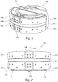
- the figure 1 represents a perspective view of a cleaning robot 100, according to a first particular embodiment of the invention.
- the cleaning robot 100 is intended for cleaning a floor, for example a floor of a room within a house or a building, independently, that is to say without the intervention of a user while browsing.
- it comprises a frame 30, driving wheels 31, a suction slot 32, and, inside an outer casing, a waste tank 33, electrical energy storage means, by a rechargeable battery pack 34, and an electronic unit or circuit (not shown) for controlling the operation and the navigation of the cleaning robot 100.
- the driving wheels 31 define a plane P1 for supporting the ground ( perpendicular to the plane of the figure 2 ), tangent to the wheels 31 visible on the figure 2 .
- the plane tangent to the wheels 31, which rest on the ground defines the floor plane P1 of the robot.
- the cleaning robot 100 is equipped with several bumpers 10A-10C and 20A-20C movably mounted relative to the frame 30, for example in translation parallel to the plane P1 ground support.
- the bumpers could be mounted pivotally movable.
- the different bumpers 10A-10C, 20A-20C are mechanically independent of each other. During movement, when the cleaning robot 100 encounters an obstacle, the latter makes contact with one or more bumpers of the robot and moves the bumped bumper (s) towards the inside of the robot. In known manner, elastic means are provided to recall the bumper or bumpers moved to a rest position after disengagement of the obstacle.
- detection means are provided arranged to detect a movement of each of the bumpers relative to the chassis 30 caused by the encounter with an obstacle.
- the control unit is arranged to control a modification of the navigation trajectory of the cleaning robot 100, following the encounter with an obstacle, depending on the result of detecting a movement of one or more of the screens.
- shocks 10A-10C and 20A-20C so as to clear the robot of the obstacle and continue navigation bypassing the latter.
- These detection means comprise a set of detection devices.
- Each bumper 10A-10C, 20A-20C is equipped with one or more detection devices able to detect a movement of this bumper with respect to the frame 30.
- a detection device equipping a bumper includes an optical sensor unit, incorporating a coupled optical transmitter and receiver, and a shutter pivoting mechanism for cutting an optical transmission between the transmitter and the receiver in the shutter position and not to cut this optical transmission between the transmitter and the receiver in the erased position (outside the closed position).
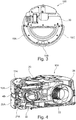
- Two shutters 21A and 11A are visible on the figure 4 .
- the detection device fitted to the bumper 10A and including the shutter 11A Take the example of the detection device fitted to the bumper 10A and including the shutter 11A, as shown in FIG. figure 4 .
- the bumper 10A In the absence of support of the bumper 10A against an obstacle (or against any other element), the bumper 10A is in the rest position and the shutter 11A is placed in the erased position so that a optical ray emitted by the transmitter is received by the receiver of the optical sensor block.
- the bumper 10A When the bumper 10A strikes an obstacle (or any other element) during a journey of the cleaning robot 100, it moves inwardly of the robot 100 relative to the frame 30, which causes the shutter to pivot 11A from its erased position to a shutter position in which the optical transmission between the transmitter and the receiver of the optical sensor block is interrupted.
- the control unit interprets this optical signal cutoff as an indication of an obstacle encountered on the robot's path. cleaning 100, at a zone with the relevant bumper 10A, and then controls the drive wheels 31 so as to divert the cleaning robot 100 from this obstacle.
- Other detection devices work the same way.
- the Figures 1 and 2 are respectively a front perspective view and a front view of the cleaning robot 100.
- the term "front” here refers to a nominal direction of advancement of the cleaning robot 100.
- the bumpers 10A-10C, 20A-20C are arranged on two stages respectively arranged at different heights, or altitudes, with respect to the ground support plane P1 of the robot.
- the bumpers 10A-10C form a first stage and the bumpers 20A-20C form a second stage.
- Each stage comprises a median plane generally crossing the bumpers in their middle and parallel to the plane P1 ground support.
- the bumpers 10A-10C, 20A-20C here have cylinder portion shapes having the same central axis AX perpendicular to the plane P1 ground support.
- the first stage has a set of three bumpers 10A-10C and the second stage also has a set of three bumpers 20A-20C.
- Each set of three bumpers 10A-10C (20A-20C) comprises two lateral bumpers 10A, 10C (20A, 20C) disposed on either side of a median plane P2 of the robot 100 (cutting the robot 100 generally in the middle), perpendicular to the ground support plane P1, and a central bumper 10B (20B) located between the two lateral bumpers 10A, 10C (20A, 20C) and traversed by the median plane P2 of the robot 100.
- Each of the side bumpers 10A, 10C (20A, 20C) is for example equipped with two motion detection devices.
- the central bumper 10B (20B) can be equipped with a single detection device. However, other configurations of the detection means could be envisaged. In any case, each bumper is equipped with at least one motion detection device of said bumper.
- a normal to the ground support plane P1 passing in a separation zone between two adjacent bumpers of the first stage passes also in a separation zone between two adjacent bumpers of the second stage (respectively between the two bumpers 20A and 20B or 20B and 20C).
- the respective bumpers of the two stages can be arranged in such a way that a normal to the ground support plane P1 which passes through a separation zone between two adjacent bumpers of one floor passes through a bumper of the other floor.
- the central bumper of one of the floors is angularly wider than the central bumper of the other floor.
- the central bumper of one of the floors is angularly offset from the central bumper of the other floor.
- the two bumper stages 10A-10C and 20A-20C form between them a housing for receiving a presence detection device 40 intended to detect the presence of an obstacle near the robot, without contact.
- the presence detection device 40 is thus interposed between the two bumper stages 10A-10C and 20A-20C. It has for example overall a form of strip in central axis cylinder portion AX. Its function is to detect the presence of an obstacle near the cleaning robot 100 without the latter coming into contact with the obstacle. It comprises one or more proximity sensors or presence detectors, for example infra-red sensors.
- an envelope surface perpendicular to the ground support plane P1 and tangential to the outer surface of the bumper or bumpers of one of the floors is also tangent to the outer surface of the bumper or the other floor.
- the bumpers on both floors are aligned vertically.
- the invention offers a simple technical solution for improving the obstacle detection which is particularly suitable for robots of great height, typically greater than 5 cm.
- the robot comprises three pairs of associated bumpers: 10A and 20A, 10B and 20B, 10C and 20C.
- the device for detecting a bumper of one of the two stages is connected in parallel with the device for detecting the associated bumper from the other stage to the unit. or the electronic control circuit.
- FIG. 5 there is shown an alternative embodiment of the central bumper of a stage (here the bumper 10B) having two oblique lateral flanks 12B, 13B, oriented towards the two adjacent lateral bumpers 10A, 10C respectively, connecting a inner face and an outer face of the central bumper 10B.
- the outer face of the central bumper 10B is widened relative to its inner face.
- the geometry of the central bumper 10B is thus improved so as to reduce or eliminate a dead zone non-detection located at the gap between two neighboring bumpers 10A-10B and 10B-10C.
- the two stages each comprise three bumpers 10A-10C and 20A-20C.
- the number of bumpers of a floor can be equal to 2 or be greater than 3.
- they are for example two side bumpers arranged from on both sides of the median plane P2 of the robot 100.
- the two stages may also comprise respective different numbers of bumpers, for example two bumpers at the bottom and three bumpers at the top.
- one of the stages comprises a single bumper and the other stage comprises several bumpers, for example two bumpers.
- the multi-bumper stage is preferably located between the ground support plane P1 and the single bumper stage.
- the upper floor has a single bumper and the low floor has several bumpers, for example two bumpers.
- the robot comprises a first stage with a single bumper and a second stage with two bumpers
- a normal ground plane P1 and passing through a separation zone between the two bumpers of the second floor passes through the bumper of the first floor. Thanks to this, the single bumper of the first stage makes it possible to cover the detection of a dead zone of non-detection situated at the separation between the two adjacent bumpers of the second stage.
- the bumpers of both floors are aligned vertically, as previously explained.
- the outer surface of the bumper or bumpers of a first of the two stages is arranged recessed with respect to an envelope surface perpendicular to the ground support plane P1 and tangential to the outer surface of the one or more bumper of the second floor, towards the inside of the robot.
- said second floor is located between the plane P1 ground support and said first floor.
- the bumper top floor is set back from the low bumper floor. The withdrawal can be a slight shift of the order of one centimeter or even a few centimeters. It makes it possible not to increase the contact force caused by an obstacle hitting the robot over its entire height (for example a wall), which could reduce the sensitivity of detection over time.
- the cleaning robot 100 could comprise more than two floors so as to cover the entire height of the robot in the case where the latter has a very large height.
Landscapes
- Engineering & Computer Science (AREA)
- Mechanical Engineering (AREA)
- Control Of Position, Course, Altitude, Or Attitude Of Moving Bodies (AREA)
- Electric Vacuum Cleaner (AREA)
- Manipulator (AREA)
Applications Claiming Priority (1)
| Application Number | Priority Date | Filing Date | Title |
|---|---|---|---|
| FR1762266A FR3075029B1 (fr) | 2017-12-15 | 2017-12-15 | Robot de nettoyage des sols |
Publications (2)
| Publication Number | Publication Date |
|---|---|
| EP3498144A1 true EP3498144A1 (de) | 2019-06-19 |
| EP3498144B1 EP3498144B1 (de) | 2021-01-06 |
Family
ID=61599372
Family Applications (1)
| Application Number | Title | Priority Date | Filing Date |
|---|---|---|---|
| EP18211741.6A Active EP3498144B1 (de) | 2017-12-15 | 2018-12-11 | Bodenreinigungsroboter |
Country Status (4)
| Country | Link |
|---|---|
| EP (1) | EP3498144B1 (de) |
| CN (2) | CN210121109U (de) |
| ES (1) | ES2848840T3 (de) |
| FR (1) | FR3075029B1 (de) |
Citations (4)
| Publication number | Priority date | Publication date | Assignee | Title |
|---|---|---|---|---|
| WO2005077240A2 (en) * | 2004-02-12 | 2005-08-25 | Arcelik Anonim Sirketi | A robot vacuum cleaner and a control method |
| KR100765848B1 (ko) * | 2006-12-28 | 2007-10-10 | (주)다사로봇 | 전방향 감지 범퍼 |
| WO2008105634A1 (en) * | 2007-02-28 | 2008-09-04 | Lg Electronics Inc. | Robot and method for controlling the robot |
| WO2015163374A1 (ja) * | 2014-04-22 | 2015-10-29 | 株式会社東芝 | 自律走行体 |
Family Cites Families (1)
| Publication number | Priority date | Publication date | Assignee | Title |
|---|---|---|---|---|
| US9483055B2 (en) * | 2012-12-28 | 2016-11-01 | Irobot Corporation | Autonomous coverage robot |
-
2017
- 2017-12-15 FR FR1762266A patent/FR3075029B1/fr not_active Expired - Fee Related
-
2018
- 2018-12-11 ES ES18211741T patent/ES2848840T3/es active Active
- 2018-12-11 EP EP18211741.6A patent/EP3498144B1/de active Active
- 2018-12-14 CN CN201822112338.2U patent/CN210121109U/zh not_active Withdrawn - After Issue
- 2018-12-14 CN CN201811533539.8A patent/CN109924930B/zh active Active
Patent Citations (4)
| Publication number | Priority date | Publication date | Assignee | Title |
|---|---|---|---|---|
| WO2005077240A2 (en) * | 2004-02-12 | 2005-08-25 | Arcelik Anonim Sirketi | A robot vacuum cleaner and a control method |
| KR100765848B1 (ko) * | 2006-12-28 | 2007-10-10 | (주)다사로봇 | 전방향 감지 범퍼 |
| WO2008105634A1 (en) * | 2007-02-28 | 2008-09-04 | Lg Electronics Inc. | Robot and method for controlling the robot |
| WO2015163374A1 (ja) * | 2014-04-22 | 2015-10-29 | 株式会社東芝 | 自律走行体 |
Also Published As
| Publication number | Publication date |
|---|---|
| CN109924930B (zh) | 2022-05-17 |
| EP3498144B1 (de) | 2021-01-06 |
| ES2848840T3 (es) | 2021-08-12 |
| FR3075029B1 (fr) | 2020-05-22 |
| CN210121109U (zh) | 2020-03-03 |
| FR3075029A1 (fr) | 2019-06-21 |
| CN109924930A (zh) | 2019-06-25 |
Similar Documents
| Publication | Publication Date | Title |
|---|---|---|
| CA2585759C (fr) | Porte rapide a rideau souple | |
| EP2841296B1 (de) | Anschlusssystem zum aufladen eines elektrischen fahrzeugs | |
| EP3799004A1 (de) | Rauchmelder | |
| FR2857844A1 (fr) | Robot de nettoyage a pare-choc supporte elastiquement | |
| US11121567B2 (en) | Mobile robot charging station | |
| FR3152217A3 (fr) | Dispositif de transmission, l'appareil de nettoyage automatique et système de robot de nettoyage | |
| FR3040953A1 (fr) | Dispositif de nettoyage d'un systeme de detection equipant un vehicule automobile | |
| EP3699115B1 (de) | Sicherheitssystem gegen das einklemmen am ende eines bandförderers und eines am ende dieses bandförderers befindlichen entladetischs, und industriemaschine, die dieses sicherheitssystem umfasst | |
| FR3156299A3 (fr) | Appareil de nettoyage automatique et système de nettoyage | |
| EP3498144B1 (de) | Bodenreinigungsroboter | |
| FR3039104A1 (fr) | Vehicule automatique guide pour le deplacement multidirectionnel de charges | |
| EP1452479A1 (de) | Hubarbeitsbühne mit Scherenmechanismus und Verfahren zur Kontrolle des Hebe-und Absenkungvorganges | |
| FR3055787A1 (fr) | Robot de nettoyage des sols | |
| EP3476265A1 (de) | Roboterstaubsauger, der einen entfernbaren handstaubsauger umfasst | |
| EP1144781B1 (de) | Sicherheitssystem für einen kraftfahrzeugflügel | |
| FR3098771A1 (fr) | Becquet destiné à être rapporté sur le hayon d’un véhicule automobile | |
| EP4640501A1 (de) | Stossfängersystem für ein rad einer landwirtschaftlichen maschine | |
| EP3394365B1 (de) | Poolreinigungsroboter und verfahren zur erkennung des anhaltens solch eines roboters | |
| FR3104501A1 (fr) | Ensemble de siège de véhicule | |
| EP4119415B1 (de) | Sattelkupplungsanordnung | |
| EP2033817A1 (de) | Öffnungsblockiersystem des hinteren Öffnungselements eines Kraftfahrzeugs | |
| WO2019179772A1 (fr) | Robot de nettoyage d'une surface vitree et dispositif de nettoyage comportant un tel robot de nettoyage | |
| FR2861112A1 (fr) | Commande automatique ou manuelle des moteurs d'entrainement en deplacement de translation du dernier module d'un abri de piscine sans guidage au sol | |
| WO2013149740A1 (fr) | Procede pour accoster un robot mobile sur une borne de r echarge et dispositif associe | |
| EP4444578B1 (de) | Beleuchtungseinrichtung für ein kraftfahrzeug |
Legal Events
| Date | Code | Title | Description |
|---|---|---|---|
| PUAI | Public reference made under article 153(3) epc to a published international application that has entered the european phase |
Free format text: ORIGINAL CODE: 0009012 |
|
| STAA | Information on the status of an ep patent application or granted ep patent |
Free format text: STATUS: THE APPLICATION HAS BEEN PUBLISHED |
|
| AK | Designated contracting states |
Kind code of ref document: A1 Designated state(s): AL AT BE BG CH CY CZ DE DK EE ES FI FR GB GR HR HU IE IS IT LI LT LU LV MC MK MT NL NO PL PT RO RS SE SI SK SM TR |
|
| AX | Request for extension of the european patent |
Extension state: BA ME |
|
| STAA | Information on the status of an ep patent application or granted ep patent |
Free format text: STATUS: REQUEST FOR EXAMINATION WAS MADE |
|
| 17P | Request for examination filed |
Effective date: 20191218 |
|
| RBV | Designated contracting states (corrected) |
Designated state(s): AL AT BE BG CH CY CZ DE DK EE ES FI FR GB GR HR HU IE IS IT LI LT LU LV MC MK MT NL NO PL PT RO RS SE SI SK SM TR |
|
| GRAP | Despatch of communication of intention to grant a patent |
Free format text: ORIGINAL CODE: EPIDOSNIGR1 |
|
| STAA | Information on the status of an ep patent application or granted ep patent |
Free format text: STATUS: GRANT OF PATENT IS INTENDED |
|
| INTG | Intention to grant announced |
Effective date: 20200716 |
|
| GRAS | Grant fee paid |
Free format text: ORIGINAL CODE: EPIDOSNIGR3 |
|
| GRAA | (expected) grant |
Free format text: ORIGINAL CODE: 0009210 |
|
| STAA | Information on the status of an ep patent application or granted ep patent |
Free format text: STATUS: THE PATENT HAS BEEN GRANTED |
|
| AK | Designated contracting states |
Kind code of ref document: B1 Designated state(s): AL AT BE BG CH CY CZ DE DK EE ES FI FR GB GR HR HU IE IS IT LI LT LU LV MC MK MT NL NO PL PT RO RS SE SI SK SM TR |
|
| REG | Reference to a national code |
Ref country code: GB Ref legal event code: FG4D Free format text: NOT ENGLISH |
|
| REG | Reference to a national code |
Ref country code: AT Ref legal event code: REF Ref document number: 1351410 Country of ref document: AT Kind code of ref document: T Effective date: 20210115 Ref country code: CH Ref legal event code: EP |
|
| REG | Reference to a national code |
Ref country code: DE Ref legal event code: R096 Ref document number: 602018011594 Country of ref document: DE |
|
| REG | Reference to a national code |
Ref country code: IE Ref legal event code: FG4D Free format text: LANGUAGE OF EP DOCUMENT: FRENCH |
|
| REG | Reference to a national code |
Ref country code: NL Ref legal event code: MP Effective date: 20210106 |
|
| REG | Reference to a national code |
Ref country code: AT Ref legal event code: MK05 Ref document number: 1351410 Country of ref document: AT Kind code of ref document: T Effective date: 20210106 |
|
| REG | Reference to a national code |
Ref country code: LT Ref legal event code: MG9D |
|
| PG25 | Lapsed in a contracting state [announced via postgrant information from national office to epo] |
Ref country code: LT Free format text: LAPSE BECAUSE OF FAILURE TO SUBMIT A TRANSLATION OF THE DESCRIPTION OR TO PAY THE FEE WITHIN THE PRESCRIBED TIME-LIMIT Effective date: 20210106 Ref country code: PT Free format text: LAPSE BECAUSE OF FAILURE TO SUBMIT A TRANSLATION OF THE DESCRIPTION OR TO PAY THE FEE WITHIN THE PRESCRIBED TIME-LIMIT Effective date: 20210506 Ref country code: NO Free format text: LAPSE BECAUSE OF FAILURE TO SUBMIT A TRANSLATION OF THE DESCRIPTION OR TO PAY THE FEE WITHIN THE PRESCRIBED TIME-LIMIT Effective date: 20210406 Ref country code: GR Free format text: LAPSE BECAUSE OF FAILURE TO SUBMIT A TRANSLATION OF THE DESCRIPTION OR TO PAY THE FEE WITHIN THE PRESCRIBED TIME-LIMIT Effective date: 20210407 Ref country code: FI Free format text: LAPSE BECAUSE OF FAILURE TO SUBMIT A TRANSLATION OF THE DESCRIPTION OR TO PAY THE FEE WITHIN THE PRESCRIBED TIME-LIMIT Effective date: 20210106 Ref country code: HR Free format text: LAPSE BECAUSE OF FAILURE TO SUBMIT A TRANSLATION OF THE DESCRIPTION OR TO PAY THE FEE WITHIN THE PRESCRIBED TIME-LIMIT Effective date: 20210106 Ref country code: BG Free format text: LAPSE BECAUSE OF FAILURE TO SUBMIT A TRANSLATION OF THE DESCRIPTION OR TO PAY THE FEE WITHIN THE PRESCRIBED TIME-LIMIT Effective date: 20210406 |
|
| REG | Reference to a national code |
Ref country code: ES Ref legal event code: FG2A Ref document number: 2848840 Country of ref document: ES Kind code of ref document: T3 Effective date: 20210812 |
|
| PG25 | Lapsed in a contracting state [announced via postgrant information from national office to epo] |
Ref country code: SE Free format text: LAPSE BECAUSE OF FAILURE TO SUBMIT A TRANSLATION OF THE DESCRIPTION OR TO PAY THE FEE WITHIN THE PRESCRIBED TIME-LIMIT Effective date: 20210106 Ref country code: RS Free format text: LAPSE BECAUSE OF FAILURE TO SUBMIT A TRANSLATION OF THE DESCRIPTION OR TO PAY THE FEE WITHIN THE PRESCRIBED TIME-LIMIT Effective date: 20210106 Ref country code: LV Free format text: LAPSE BECAUSE OF FAILURE TO SUBMIT A TRANSLATION OF THE DESCRIPTION OR TO PAY THE FEE WITHIN THE PRESCRIBED TIME-LIMIT Effective date: 20210106 Ref country code: PL Free format text: LAPSE BECAUSE OF FAILURE TO SUBMIT A TRANSLATION OF THE DESCRIPTION OR TO PAY THE FEE WITHIN THE PRESCRIBED TIME-LIMIT Effective date: 20210106 Ref country code: AT Free format text: LAPSE BECAUSE OF FAILURE TO SUBMIT A TRANSLATION OF THE DESCRIPTION OR TO PAY THE FEE WITHIN THE PRESCRIBED TIME-LIMIT Effective date: 20210106 |
|
| PG25 | Lapsed in a contracting state [announced via postgrant information from national office to epo] |
Ref country code: IS Free format text: LAPSE BECAUSE OF FAILURE TO SUBMIT A TRANSLATION OF THE DESCRIPTION OR TO PAY THE FEE WITHIN THE PRESCRIBED TIME-LIMIT Effective date: 20210506 |
|
| REG | Reference to a national code |
Ref country code: DE Ref legal event code: R097 Ref document number: 602018011594 Country of ref document: DE |
|
| PG25 | Lapsed in a contracting state [announced via postgrant information from national office to epo] |
Ref country code: CZ Free format text: LAPSE BECAUSE OF FAILURE TO SUBMIT A TRANSLATION OF THE DESCRIPTION OR TO PAY THE FEE WITHIN THE PRESCRIBED TIME-LIMIT Effective date: 20210106 Ref country code: EE Free format text: LAPSE BECAUSE OF FAILURE TO SUBMIT A TRANSLATION OF THE DESCRIPTION OR TO PAY THE FEE WITHIN THE PRESCRIBED TIME-LIMIT Effective date: 20210106 Ref country code: SM Free format text: LAPSE BECAUSE OF FAILURE TO SUBMIT A TRANSLATION OF THE DESCRIPTION OR TO PAY THE FEE WITHIN THE PRESCRIBED TIME-LIMIT Effective date: 20210106 |
|
| PLBE | No opposition filed within time limit |
Free format text: ORIGINAL CODE: 0009261 |
|
| STAA | Information on the status of an ep patent application or granted ep patent |
Free format text: STATUS: NO OPPOSITION FILED WITHIN TIME LIMIT |
|
| PG25 | Lapsed in a contracting state [announced via postgrant information from national office to epo] |
Ref country code: DK Free format text: LAPSE BECAUSE OF FAILURE TO SUBMIT A TRANSLATION OF THE DESCRIPTION OR TO PAY THE FEE WITHIN THE PRESCRIBED TIME-LIMIT Effective date: 20210106 Ref country code: SK Free format text: LAPSE BECAUSE OF FAILURE TO SUBMIT A TRANSLATION OF THE DESCRIPTION OR TO PAY THE FEE WITHIN THE PRESCRIBED TIME-LIMIT Effective date: 20210106 Ref country code: RO Free format text: LAPSE BECAUSE OF FAILURE TO SUBMIT A TRANSLATION OF THE DESCRIPTION OR TO PAY THE FEE WITHIN THE PRESCRIBED TIME-LIMIT Effective date: 20210106 |
|
| 26N | No opposition filed |
Effective date: 20211007 |
|
| PG25 | Lapsed in a contracting state [announced via postgrant information from national office to epo] |
Ref country code: AL Free format text: LAPSE BECAUSE OF FAILURE TO SUBMIT A TRANSLATION OF THE DESCRIPTION OR TO PAY THE FEE WITHIN THE PRESCRIBED TIME-LIMIT Effective date: 20210106 |
|
| PG25 | Lapsed in a contracting state [announced via postgrant information from national office to epo] |
Ref country code: SI Free format text: LAPSE BECAUSE OF FAILURE TO SUBMIT A TRANSLATION OF THE DESCRIPTION OR TO PAY THE FEE WITHIN THE PRESCRIBED TIME-LIMIT Effective date: 20210106 |
|
| PG25 | Lapsed in a contracting state [announced via postgrant information from national office to epo] |
Ref country code: IS Free format text: LAPSE BECAUSE OF FAILURE TO SUBMIT A TRANSLATION OF THE DESCRIPTION OR TO PAY THE FEE WITHIN THE PRESCRIBED TIME-LIMIT Effective date: 20210506 |
|
| PG25 | Lapsed in a contracting state [announced via postgrant information from national office to epo] |
Ref country code: MC Free format text: LAPSE BECAUSE OF FAILURE TO SUBMIT A TRANSLATION OF THE DESCRIPTION OR TO PAY THE FEE WITHIN THE PRESCRIBED TIME-LIMIT Effective date: 20210106 |
|
| REG | Reference to a national code |
Ref country code: CH Ref legal event code: PL |
|
| REG | Reference to a national code |
Ref country code: BE Ref legal event code: MM Effective date: 20211231 |
|
| PG25 | Lapsed in a contracting state [announced via postgrant information from national office to epo] |
Ref country code: LU Free format text: LAPSE BECAUSE OF NON-PAYMENT OF DUE FEES Effective date: 20211211 Ref country code: IE Free format text: LAPSE BECAUSE OF NON-PAYMENT OF DUE FEES Effective date: 20211211 |
|
| PG25 | Lapsed in a contracting state [announced via postgrant information from national office to epo] |
Ref country code: BE Free format text: LAPSE BECAUSE OF NON-PAYMENT OF DUE FEES Effective date: 20211231 |
|
| PG25 | Lapsed in a contracting state [announced via postgrant information from national office to epo] |
Ref country code: LI Free format text: LAPSE BECAUSE OF NON-PAYMENT OF DUE FEES Effective date: 20211231 Ref country code: CH Free format text: LAPSE BECAUSE OF NON-PAYMENT OF DUE FEES Effective date: 20211231 |
|
| PG25 | Lapsed in a contracting state [announced via postgrant information from national office to epo] |
Ref country code: NL Free format text: LAPSE BECAUSE OF NON-PAYMENT OF DUE FEES Effective date: 20210206 Ref country code: CY Free format text: LAPSE BECAUSE OF FAILURE TO SUBMIT A TRANSLATION OF THE DESCRIPTION OR TO PAY THE FEE WITHIN THE PRESCRIBED TIME-LIMIT Effective date: 20210106 |
|
| PG25 | Lapsed in a contracting state [announced via postgrant information from national office to epo] |
Ref country code: HU Free format text: LAPSE BECAUSE OF FAILURE TO SUBMIT A TRANSLATION OF THE DESCRIPTION OR TO PAY THE FEE WITHIN THE PRESCRIBED TIME-LIMIT; INVALID AB INITIO Effective date: 20181211 |
|
| PGFP | Annual fee paid to national office [announced via postgrant information from national office to epo] |
Ref country code: IT Payment date: 20231211 Year of fee payment: 6 |
|
| PGFP | Annual fee paid to national office [announced via postgrant information from national office to epo] |
Ref country code: ES Payment date: 20240108 Year of fee payment: 6 |
|
| PG25 | Lapsed in a contracting state [announced via postgrant information from national office to epo] |
Ref country code: MK Free format text: LAPSE BECAUSE OF FAILURE TO SUBMIT A TRANSLATION OF THE DESCRIPTION OR TO PAY THE FEE WITHIN THE PRESCRIBED TIME-LIMIT Effective date: 20210106 |
|
| PG25 | Lapsed in a contracting state [announced via postgrant information from national office to epo] |
Ref country code: MT Free format text: LAPSE BECAUSE OF FAILURE TO SUBMIT A TRANSLATION OF THE DESCRIPTION OR TO PAY THE FEE WITHIN THE PRESCRIBED TIME-LIMIT Effective date: 20210106 |
|
| PG25 | Lapsed in a contracting state [announced via postgrant information from national office to epo] |
Ref country code: IT Free format text: LAPSE BECAUSE OF NON-PAYMENT OF DUE FEES Effective date: 20241211 |
|
| PG25 | Lapsed in a contracting state [announced via postgrant information from national office to epo] |
Ref country code: TR Free format text: LAPSE BECAUSE OF FAILURE TO SUBMIT A TRANSLATION OF THE DESCRIPTION OR TO PAY THE FEE WITHIN THE PRESCRIBED TIME-LIMIT Effective date: 20210106 |
|
| PGFP | Annual fee paid to national office [announced via postgrant information from national office to epo] |
Ref country code: GB Payment date: 20251229 Year of fee payment: 8 |
|
| PGFP | Annual fee paid to national office [announced via postgrant information from national office to epo] |
Ref country code: FR Payment date: 20251230 Year of fee payment: 8 |
|
| REG | Reference to a national code |
Ref country code: ES Ref legal event code: FD2A Effective date: 20260128 |
|
| PG25 | Lapsed in a contracting state [announced via postgrant information from national office to epo] |
Ref country code: ES Free format text: LAPSE BECAUSE OF NON-PAYMENT OF DUE FEES Effective date: 20241212 |
|
| PGFP | Annual fee paid to national office [announced via postgrant information from national office to epo] |
Ref country code: DE Payment date: 20251231 Year of fee payment: 8 |