CROSS REFERENCE TO RELATED APPLICATION
-
The present application claims priority to Korean Patent Application No.
10-2017-0174311, filed December 18, 2017 , the entire contents of which is incorporated herein for all purposes by this reference.
BACKGROUND OF THE INVENTION
Field of the Invention
-
The present invention relates generally to an ampoule for storing a cosmetic liquid, the ampoule mainly storing an oil-type cosmetic liquid and discharging the same in use. More particularly, the present invention relates to an ampoule for storing a cosmetic liquid, in which a required amount of cosmetic liquid is discharged to outside due to air pressure by gently shaking a containing portion while holding it upside down, whereby the cosmetic liquid is discharged and used very easily, conveniently, and hygienically.
Description of the Related Art
-
In general, contents to be sealed and stored in a sterilized state, such as injections, health tonics, liquid medicines for internal use, etc., are mainly packaged in a container called a glass ampoule. Such a container is manufactured by injecting the contents into a thin glass tube and by fusing a tip thereof with an open flame, etc., thus hermetically sealing the thin glass tube.
-
While such a glass ampoule is very hygienic, there is a high risk of breakage during handling. In addition, there is a possibility of injury when a user snaps off the tip of the glass ampoule by hand to use the ampoule contents, whereby the user's hand may be cut from sharp edges of the glass ampoule.
-
During opening of the glass ampoule, microscopic glass shards may be introduced into the ampoule contents, and thus the ampoule contents may be injected into the body with the glass shards, causing blood clots, etc.
-
In order to solve such a problem of the glass ampoule, a plastic ampoule has recently been developed and used. However, such a plastic ampoule is generally manufactured by a method so-called blowing-filling-sealing (BFS) in which a series of processes of blow molding a container using a synthetic resin, of filling contents into the container, and of sealing an opening of the container are carried out sequentially.
-
However, the plastic ampoule itself has toughness unlike the glass ampoule, and thus the container may not be easily opened only by impact acting on the upper part of the container. Accordingly, a neck portion and a tip portion must be forcibly removed from a container body by twisting off a separate wing knob portion.
-
Herein, the plastic ampoule is opened while leaving a so-called plastic residue in which edges of the broken area are stretched upon opening unlike the glass ampoule having the sharp edges. Accordingly, the edges of the plastic ampoule are likely to be contaminated by the user's hand during opening, and thus there is a high possibility of unintentionally contaminating the contents contained in the ampoule.
-
Thus, in order to solve such a problem, the thickness of a parison may be made as thin as possible, or a part of the surface of a breaking portion may be scored using a sharp metal such as a blade. However, because the parison is stretched by gravity, the method of thinning the parison has technical limitations and also the method of scoring a part of the surface of the breaking portion has limitations on complete removal of the plastic residue.
-
In addition, the plastic ampoule in the related art is structured such that a long neck portion having a small diameter is formed at the upper part of the plastic ampoule in order to facilitate separating of the tip portion of the plastic ampoule. When the plastic ampoule is laid sideways during product storage and transportation, the neck portion is filled with the contents and thus the contents in the neck portion may remain therein rather than falling back into the container even when allowing the plastic ampoule to stand up again. Accordingly, it is required for contents remaining in the neck portion to fall back to the container before opening in every use, resulting in user inconvenience.
-
On the other hand, in an effort to solve the problem of breaking the neck portion of the plastic ampoule in the related art, Patent Document 1 discloses a plastic ampoule in which a ring-shaped scoring groove is formed both on the inner and outer circumferences of a neck portion provided between a body portion and a knob portion, such that the neck portion is made thin, resulting in more easy and quick breaking of neck portion with an external force for bending the knob portion.
-
In addition, in the relate art, there is a container for withdrawing its contents, such as a cosmetic liquid, etc., using a syringe. However, withdrawing the contents of the container into the syringe is repeatedly performed in every use by holding the syringe in one hand while holding the container in the other hand, resulting in user inconvenience.
-
Moreover, in order to solve the problem associated with the use of the glass ampoule, Patent Document 2 discloses an ampoule in which a piston is fitted into a lower opening end of an ampoule body to store the contents of the ampoule injected into the ampoule body, and then the piston is forcibly pushed up by using a handle portion covering an injection and discharge portion of a body of the ampoule, whereby the contents of the ampoule are divided into several doses and used.
Documents of Related Art
-
- (Patent document 1) Korean Patent No. 10-1761570 (published on July 26, 2017 )
- (Patent document 2) Korean Utility Model Registration No. 20-0461736 (published on August 3, 2012 )
SUMMARY OF THE INVENTION
-
Accordingly, the present invention has been made keeping in mind the above problems occurring in the related art, and the present invention provides an ampoule for storing a cosmetic liquid, different from an ampoule structure in the related art in which a neck portion is broken to use the cosmetic liquid, in which the ampoule for storing the cosmetic liquid is configured such that a required amount of cosmetic liquid is discharged due to pressure of air introduced from outside by opening a cap portion and then gently shaking a containing portion while holding it upside down. Thus, the cosmetic liquid is discharged and used more hygienically and safely without any relation to the structure or material of the containing portion, thereby further enhancing convenience and stability of use of a product.
-
In order to achieve the above object, according to one aspect of the present invention, there is provided an ampoule for storing a cosmetic liquid, the ampoule including: a containing portion in which the cosmetic liquid is contained through an injection hole; a discharge mechanism having a discharge tube airtightly coupled to an inner circumferential surface of the injection hole of the containing portion in a press-fitted manner and configured to discharge the cosmetic liquid to outside, and an air inlet tube allowing outside air to be introduced into the containing portion upon cosmetic liquid discharge operation; and a cap portion opening and closing the discharge tube or the air inlet tube while being opened and closed with respect to the discharge mechanism.
-
According to the present invention, the discharge mechanism may include an airtight coupling portion airtightly coupled to the inner circumferential surface of the injection hole of the containing portion, and an opening and closing operation portion provided at a position higher than the airtight coupling portion, wherein the airtight coupling portion and the opening and closing operation portion may be open from a bottom surface of the airtight coupling portion to a top of the opening and closing operation portion, the discharge tube discharging the cosmetic liquid to the outside may be provided by passing through the bottom surface, and the air inlet tube may be provided at the bottom surface separately from the discharge tube such that the outside air is allowed to be introduced into the containing portion.
-
According to the present invention, the discharge tube may extend such that an upper end thereof is positioned higher than an upper end of the opening and closing operation portion.
-
According to the present invention, the airtight coupling portion of the discharge mechanism may be provided with a stop protrusion engaged with a serration formed on the injection hole of the containing portion, and a ring-shaped airtight rim allowing the airtight coupling portion of the discharge mechanism to be airtightly coupled to the inner circumferential surface of the injection hole.
-
According to the present invention, a close contact surface may be provided on an inner surface of the cap portion to correspond to an upper end surface of the opening and closing operation portion and an upper end surface of the discharge tube of the discharge mechanism, such that the close contact surface is in close contact with the upper end surface of the opening and closing operation portion and the upper end surface of the discharge tube.
-
According to the present invention, the air inlet tube provided by passing through the bottom surface of the airtight coupling portion may be at least one air inlet tube.
-
According to the present invention, the ampoule may further include an auxiliary air inlet hole formed by passing through the bottom surface of the airtight coupling portion, in addition to the air inlet tube, wherein the auxiliary air inlet hole may be at least one auxiliary air inlet hole.
-
According to the present invention, the discharge mechanism and the cap portion may be made of materials different from each other.
-
According to the present invention, the discharge mechanism may be made of a soft material, and the cap portion may be made of a relatively hard material.
-
According to the present invention, the discharge mechanism and the cap portion may be opened and closed by screw engagement.
-
According to the present invention, the cap portion is separated from the discharge mechanism and thus is opened, and then the containing portion is gently shaken while being held upside down, whereby a required amount of cosmetic liquid is discharged to the outside due to air pressure. Consequently, it is possible to discharge and use the cosmetic liquid very easily, conveniently, and hygienically, and to provide an ampoule of a form which can be disposable or used multiple times according to the use of the cosmetic liquid.
-
Further, the discharge mechanism and the cap portion are made of materials different from each other, whereby it is possible to obtain an improved airtight coupling therebetween.
-
Further, at least one air inlet tube is formed according to a difference in specific gravity of cosmetic liquids whereby it is possible to efficiently discharge the cosmetic liquids having the specific gravity difference, and the auxiliary air inlet hole is further formed whereby inflow of air can be facilitated.
-
Further, the injection hole of the containing portion is provided with no thread portion formed on the outer circumferential surface thereof, whereby injection or blow molding of the containing portion can be remarkably simplified.
BRIEF DESCRIPTION OF THE DRAWINGS
-
The above and other objects, features and other advantages of the present invention will be more clearly understood from the following detailed description when taken in conjunction with the accompanying drawings, in which:
- FIG. 1 is a separated sectional view showing an ampoule for storing a cosmetic liquid according to the present invention;
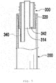
- FIG. 2 is an assembled sectional view of FIG. 1;
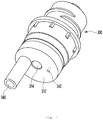
- FIG. 3 is an extracted perspective view showing a discharge mechanism according to an embodiment of the present invention;
- FIG. 4 is an extracted perspective view showing a discharge mechanism according to another embodiment of the present invention;
- FIG. 5 is a sectional view showing a state in which the discharge mechanism of FIG. 4 is assembled;
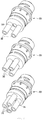
- FIG. 6 is an extracted perspective view showing discharge mechanisms according to yet another embodiment of the present invention;
- FIG. 7 is a perspective view showing various embodiments of the ampoule for storing the cosmetic liquid according to the present invention; and
- FIG. 8 is a sectional view showing a use state in which a cosmetic solution is discharged after removing a cap portion according to the present invention.
DETAILED DESCRIPTION OF THE INVENTION
-
Hereinbelow, exemplary embodiments of the present invention will be described in detail with reference to the accompanying drawings. Throughout the drawings, the same reference numerals will refer to the same or like parts.
-
Referring to FIGS. 1 to 3, an ampoule 100 for storing a cosmetic liquid according to the present invention largely includes a containing portion 200, a discharge mechanism 300, and a cap portion 400.
-
The containing portion 200 includes a storage space 210 having a predetermined area in which the cosmetic liquid is stored, and an injection hole 220 communicating with the storage space. The injection hole 220 is formed integrally with the containing portion 200 by extending from an upper end of a side thereof such that the injection hole 220 communicates with the storage space 210.
-
Because the containing portion 200 is configured such that the injection hole 220 is provided with no thread portion in the related art which is formed on an outer circumference thereof for opening and closing of the cap portion 400, the containing portion 200 is remarkably improved in injection or blow moldability.
-
Furthermore, the containing portion 200 may have an appropriate size and shape in consideration of the number of times of use of the cosmetic liquid, that is, once or multiple times, more preferably equal to or less than five times. The containing portion 200 may be made of various materials such as glass materials, synthetic resin materials, etc.
-
Referring to FIG. 7, it will be appreciated that the shape or size of the containing portion 200 may vary.
-
A filling operation is performed such that the cosmetic liquid is filled into the storage space 210 of the containing portion 200 through the injection hole 220.
-
The discharge mechanism 300 includes an airtight coupling portion 310 airtightly coupled to an inner circumferential surface of the injection hole 220 of the containing portion 200, and an opening and closing operation portion 320. A stepped flange 330 protrudes radially outwardly from the periphery of the discharge mechanism 300 at a position between the airtight coupling portion 310 and the opening and closing operation portion 320, and is seated on an upper end of the injection hole 220 upon assembly.
-
The airtight coupling portion 310 and the opening and closing operation portion 320 are provided integrally with each other to be open from a bottom surface 312 of the airtight coupling portion 310 to a top of the opening and closing operation portion 320.
-
A discharge tube 314 is provided at the bottom surface 312 of the airtight coupling portion 310. The discharge tube 314 serves to securely discharge the cosmetic liquid from the storage space 210 of the containing portion 200 to outside.
-
It is preferable that the discharge tube 314 extends outwardly of an upper end surface of the opening and closing operation portion 320 and thus protrudes therefrom to facilitate discharging of the cosmetic liquid.
-
An air inlet tube 340 is provided at the bottom surface 312 of the airtight coupling portion 310 separately from the discharge tube 314, such that air that is introduced from outside through an open upper end of the opening and closing operation portion 320 is supplied into the storage space 210 of the containing portion 200.
-
The air inlet tube 340 may vary in size or number depending on a difference in specific gravity of cosmetic liquids.
-
The air inlet tube 340 extends by passing through the bottom surface 312 of the airtight coupling portion 310.
-
Accordingly, when the cap portion 400 is opened, air introduced through an internal space of the opening and closing operation portion 320 is allowed to be supplied into the storage space 210 of the containing portion 200 through the air inlet tube 340 to reach a deep position in the storage space 210, whereby discharging of the cosmetic liquid is more efficiently performed.
-
According to the present invention, the size, shape, or the number of the air inlet tube 340 may vary based on comprehensive consideration of the difference in specific gravity of cosmetic liquids, a discharge amount of the cosmetic liquid, etc.
-
This can be fully understood with reference to the discharge mechanism 300 shown in FIG. 6.
-
In addition, as shown in FIGS. 4 and 5, the ampoule 100 may further include an auxiliary air inlet hole 342 formed by passing through the bottom surface 312 of the discharge mechanism 300, in addition to the air inlet tube 340. Herein, the auxiliary air inlet hole 342 may have a size smaller than a size of the air inlet tube 340.
-
Furthermore, even though only one auxiliary air inlet hole 342 is shown in the drawings, at least one auxiliary air inlet hole 342 may be provided as required.
-
The communication of air is more efficiently performed through the auxiliary air inlet hole 342, thus inducing the cosmetic liquid to be more efficiently discharged.
-
The opening and closing operation portion 320 is provided with a male thread 322 formed on the outer circumferential surface thereof for screw engagement.
-
Furthermore, the airtight coupling portion 310 is provided with a stop protrusion 316 formed on an outer circumferential surface thereof and engaged with a serration 222 formed on the inner circumferential surface of the injection hole 220 of the containing portion 200.
-
It is preferable that the stop protrusion 316 is formed in a shape corresponding to the serration 222 in consideration of relationship between the stop protrusion 316 and the serration 222 that are engaged with each other.
-
In addition, the airtight coupling portion 310 is provided with a ring-shaped airtight rim 318 such that the discharge mechanism 300 is airtightly coupled to the inner circumferential surface of the injection hole 220 in a press-fitted manner.
-
The ring-shaped airtight rim 318 may be at least one ring-shaped airtight rim depending on the degree of airtightness required.
-
The discharge mechanism 300 can be prevented from rotating arbitrarily by the stop protrusion 316 engaged with the serration 222 during a screw opening and closing operation. In addition, the inner circumferential surface of the injection hole 220 is blocked by the ring-shaped airtight rim 318, whereby the cosmetic liquid can be prevented from leaking through the inner circumference of the injection hole 220.
-
By provision of the ring-shaped airtight rim 318, the discharge mechanism 300 can provide a strong fitting force against the inner circumference of the injection hole 220, thus enabling airtight coupling therebetween.
-
The cap portion 400 is opened and closed with respect to the opening and closing operation portion 320 of the discharge mechanism 300 and thus to open or close the discharge tube 314 and the air inlet tube 340 of the discharge mechanism. The cap portion 400 is provided with a female thread 410 formed on an inner surface thereof and engaged with the male thread 322 formed on the opening and closing operation portion 320 of the discharge mechanism 300.
-
The cap portion 400 is provided with a stepped close contact surface 420 provided on the inner surface thereof to correspond to an upper end surface of the opening and closing operation portion 320 and an upper end surface of the discharge tube 314, such that the close contact surface 420 is in close contact with the upper end surface of the opening and closing operation portion 320 and the upper end surface of the discharge tube 314.
-
According to the present invention, the discharge mechanism 300 and the cap portion 400 may variously implemented depending on the application thereof or the shape of the containing portion 200 as shown in FIG. 7.
-
According to the present invention, it is preferable that the discharge mechanism 300 and the cap portion 400 are made of materials different from each other.
-
In other words, it is preferable that the discharge mechanism 300 is made of a soft material, and the cap portion 400 is made of a relatively hard material, or vice versa.
-
In a case where the discharge mechanism 300 is made of a soft material, airtight coupling may be achieved when the discharge mechanism 300 is coupled to the injection hole 220 of the containing portion 200. Accordingly, it is preferable to use a soft material having a certain degree of elasticity as compared with a hard material which makes it difficult to achieve such a function. As one example thereof, a rubber material such as PE, etc. may be used.
-
Furthermore, it is preferable that the cap portion 400 is made of a relatively hard material to achieve an improved airtight coupling with the discharge mechanism 300. As one example thereof, a material such as PP, ABS, etc. may be used.
-
As such, the discharge mechanism 300 is made of a soft material and the cap portion 400 is made of a hard material, whereby particularly when the cap portion 400 is coupled to the discharge mechanism 300, the upper end surface of the discharge tube 314 of the discharge mechanism 300 and the upper end surface of the opening and closing operation portion 320 come into elastic close contact with the close contact surface 420 provided on the inner surface of the cap portion 400, thus providing stable airtightness.
-
Hereinafter, a description will be given of a use state in which the cosmetic liquid stored in the storage space 210 of the containing portion 200 is discharged once or multiple times by using the ampoule 100 for storing the cosmetic liquid according to the present invention.
-
First, before the cosmetic liquid is discharged, the cap portion 400 is kept in a state in which the cap portion 400 is airtightly coupled to the opening and closing operation portion 320 of the discharge mechanism 300 by screw engagement. Accordingly, even though the containing portion 200 is held upside down, leakage of the cosmetic liquid can be prevented.
-
In other words, the upper end surface of the discharge tube 314 of the discharge mechanism 300 and the upper end surface of the opening and closing operation portion 320 are in close contact with the close contact surface 420 that is provided on the inner surface of the cap portion 400 to correspond to the upper end surface of the discharge tube 314 of the discharge mechanism 300 and the upper end surface of the opening and closing operation portion 320, and thus is kept in an airtight state. In addition, the inner circumferential surface of the injection hole 220 of the containing portion 200 is in close contact with the discharge mechanism 300 by the ring-shaped airtight rim 318 of the discharge mechanism 300 in an airtight manner, thus preventing leakage of the cosmetic liquid.
-
In a case where the cosmetic solution is to be discharged and used in such a state, the cap portion 400 is opened to be removed from the discharge mechanism 300.
-
When the cap portion 400 is opened and removed from the discharge mechanism 300 as described above, the air inlet tube 340 is opened to allow entrance of outside air, and at the same time, the discharge tube 314 is also opened.
-
In such a state, as shown in FIG. 8, when a user holds the containing portion 200 upside down and gently shakes it, the cosmetic liquid stored in the storage space 210 of the containing portion 200 is discharged to outside through the discharge tube 314 due to pressure of air introduced through the air inlet tube 340.
-
Thus, a required amount of cosmetic liquid can be discharged once or multiple times in the above-described manner. After discharging is completed, the cap portion 400 is closed again with respect to the discharge mechanism 300, whereby the cosmetic liquid can be stably stored in an airtight state.
-
Although a preferred embodiment of the present invention has been described for illustrative purposes, those skilled in the art will appreciate that various modifications, additions and substitutions are possible, without departing from the scope and spirit of the invention as disclosed in the accompanying claims.