EP3497970B1 - Mobilität in 5g mit übergabe oder zellenneuauswahl in abhängigkeit der veränderung des empfangsbereichs der benutzerebenenfunktionalität - Google Patents
Mobilität in 5g mit übergabe oder zellenneuauswahl in abhängigkeit der veränderung des empfangsbereichs der benutzerebenenfunktionalität Download PDFInfo
- Publication number
- EP3497970B1 EP3497970B1 EP17757902.6A EP17757902A EP3497970B1 EP 3497970 B1 EP3497970 B1 EP 3497970B1 EP 17757902 A EP17757902 A EP 17757902A EP 3497970 B1 EP3497970 B1 EP 3497970B1
- Authority
- EP
- European Patent Office
- Prior art keywords
- base station
- tupf
- cell
- session
- communication device
- Prior art date
- Legal status (The legal status is an assumption and is not a legal conclusion. Google has not performed a legal analysis and makes no representation as to the accuracy of the status listed.)
- Active
Links
- 230000008859 change Effects 0.000 title description 5
- 230000001419 dependent effect Effects 0.000 title 1
- 238000004891 communication Methods 0.000 claims description 109
- 238000000034 method Methods 0.000 claims description 34
- 238000013507 mapping Methods 0.000 claims description 19
- 230000002085 persistent effect Effects 0.000 claims description 5
- 238000005259 measurement Methods 0.000 description 29
- 230000006870 function Effects 0.000 description 13
- 238000007726 management method Methods 0.000 description 12
- 230000011664 signaling Effects 0.000 description 10
- 238000010586 diagram Methods 0.000 description 8
- 238000005516 engineering process Methods 0.000 description 6
- 230000005540 biological transmission Effects 0.000 description 5
- 230000002459 sustained effect Effects 0.000 description 5
- CIWBSHSKHKDKBQ-JLAZNSOCSA-N Ascorbic acid Chemical compound OC[C@H](O)[C@H]1OC(=O)C(O)=C1O CIWBSHSKHKDKBQ-JLAZNSOCSA-N 0.000 description 4
- 238000012986 modification Methods 0.000 description 4
- 230000004048 modification Effects 0.000 description 4
- 230000001413 cellular effect Effects 0.000 description 3
- 238000013500 data storage Methods 0.000 description 2
- 230000007774 longterm Effects 0.000 description 2
- 230000008569 process Effects 0.000 description 2
- 241000700159 Rattus Species 0.000 description 1
- 230000002776 aggregation Effects 0.000 description 1
- 238000004220 aggregation Methods 0.000 description 1
- 238000011161 development Methods 0.000 description 1
- 230000018109 developmental process Effects 0.000 description 1
- 230000007246 mechanism Effects 0.000 description 1
- 238000010295 mobile communication Methods 0.000 description 1
- 238000005204 segregation Methods 0.000 description 1
Images


Classifications
-
- H—ELECTRICITY
- H04—ELECTRIC COMMUNICATION TECHNIQUE
- H04W—WIRELESS COMMUNICATION NETWORKS
- H04W36/00—Hand-off or reselection arrangements
- H04W36/0005—Control or signalling for completing the hand-off
- H04W36/0011—Control or signalling for completing the hand-off for data sessions of end-to-end connection
- H04W36/0033—Control or signalling for completing the hand-off for data sessions of end-to-end connection with transfer of context information
-
- H—ELECTRICITY
- H04—ELECTRIC COMMUNICATION TECHNIQUE
- H04W—WIRELESS COMMUNICATION NETWORKS
- H04W36/00—Hand-off or reselection arrangements
- H04W36/0005—Control or signalling for completing the hand-off
- H04W36/0011—Control or signalling for completing the hand-off for data sessions of end-to-end connection
-
- H—ELECTRICITY
- H04—ELECTRIC COMMUNICATION TECHNIQUE
- H04W—WIRELESS COMMUNICATION NETWORKS
- H04W36/00—Hand-off or reselection arrangements
- H04W36/04—Reselecting a cell layer in multi-layered cells
-
- H—ELECTRICITY
- H04—ELECTRIC COMMUNICATION TECHNIQUE
- H04W—WIRELESS COMMUNICATION NETWORKS
- H04W36/00—Hand-off or reselection arrangements
- H04W36/12—Reselecting a serving backbone network switching or routing node
Definitions
- the present invention relates to a communication system.
- the invention has particular but not exclusive relevance to wireless communication systems and devices thereof operating according to the 3rd Generation Partnership Project (3GPP) standards or equivalents or derivatives thereof.
- 3GPP 3rd Generation Partnership Project
- the invention has particular although not exclusive relevance to mobility in the so-called 'Next Generation' systems.
- LTE Long Term Evolution
- EPC Evolved Packet Core
- E-UTRAN Evolved UMTS Terrestrial Radio Access Network
- a NodeB or an eNB in LTE
- the core network hosts functionality for subscriber management, mobility management, charging, security, and call/session management (amongst others), and provides connection for communication devices to external networks, such as the Internet.
- Communication devices might be, for example, mobile communication devices such as mobile telephones, smartphones, user equipment, personal digital assistants, laptop/ tablet computers, web browsers, e-book readers and/or the like. Such mobile (or even generally stationary) devices are typically operated by a user, although it is also possible to connect so-called 'Internet of Things' (IoT) devices and similar machine-type communication (MTC) devices to the network.
- IoT Internet of Things
- MTC machine-type communication
- the present application refers to mobile devices (or UEs) in the description but it will be appreciated that the technology described can be implemented on any communication devices (mobile and/or generally stationary) that can connect to a communications network for sending/receiving data, regardless of whether such communication devices are controlled by human input or software instructions stored in memory.
- the term '5G' refers to an evolving communication technology that is expected to support a variety of applications and services.
- 5G networks Various details of 5G networks are described in, for example, the 'NGMN 5G White Paper' V1.0 by the Next Generation Mobile Networks (NGMN) Alliance, which document is available from https://www.ngmn.org/5g-white-paper.html.
- NVMN Next Generation Mobile Networks
- 3GPP intends to support 5G by way of the so-called 3GPP Next Generation (NextGen) radio access network (RAN) and the 3GPP NextGen core network.
- NextGen Next Generation
- RAN radio access network
- NextGen core network 3GPP NextGen core network
- 3GPP technical report (TR) 23.799 V0.7.0 describes a possible architecture and general procedures for NextGen (5G) systems planned for Release 14 of the 3GPP standards.
- This technical report introduces the so-called Terminating User Plane Function (TUPF) which is effectively a logical network node coupled to one or more cells (base stations) and which terminates the 3GPP user plane and interfaces with the data network.
- PDU protocol data unit
- 3GPP TR 23.799 also describes (in section 6.6) three possibilities for providing support for session and service continuity (SSC) for UEs in NextGen systems. These possibilities are referred to as 'SSC modes', and they are defined as follows:
- SSC modes apply per PDU session.
- a UE may request different SSC modes for its different PDU sessions, i.e. different PDU sessions which are active in parallel for the same UE may have different SSC modes.
- the associated SSC mode is not changed during the lifetime of a PDU session.
- a UE can determine the SSC mode required for an application when an application in the UE starts a new flow (i.e. opens a new socket).
- the application indicates the type of session continuity required by this flow. This may be indicated using one of the sockets application programming interface (API) extensions specified in e.g. Request for Comments (RFC) no. 3493, RFC no. 3542, and in Internet-Draft "draft-ietf-dmm-ondemand-mobility" (V7) published by the Internet Engineering Task Force (IETF).
- RRC request for Comments
- V7 Internet-Draft "draft-ietf-dmm-ondemand-mobility"
- IETF Internet Engineering Task Force
- the application may use an already specified software API to indicate what type of session continuity is required.
- IP session continuity, IP address reachability, nomadic (i.e. non-sustained), sustained (i.e. session-lasting), and fixed IP address can be found in draft-ietf-dmm-ondemand-mobility
- IP (Internet Protocol) session continuity is defined as the ability to maintain an ongoing IP session by keeping the same local end-point IP address throughout the session despite the mobile host changing its point of attachment within the IP network topology (even though the IP address of the host may change between two independent IP sessions, it does not jeopardize the IP session continuity. IP session continuity is essential for mobile hosts to maintain ongoing flows without any interruption.
- IP address reachability is defined as the ability to maintain the same IP address for an extended period of time. In this case, the IP address remains the same across independent IP sessions, and even in the absence of any IP session.
- the IP address may be published in a long-term registry (e.g. a domain name server, DNS) and it is made available for serving incoming connections.
- DNS domain name server
- a nomadic (or non-persistent) IP address is a type of IP address that provides neither IP session continuity nor IP address reachability.
- a nomadic IP address is obtained from the serving IP gateway and it is not maintained across gateway changes. In other words, the nomadic IP address may be released and replaced by a new IP address when the IP gateway changes due to the movement of the mobile host (e.g. UE).
- While certain applications e.g. servers, virtual local area network (VLAN) clients, and secure shell (SSH) sessions
- applications with short-lived IP sessions can use sustained IP addresses.
- Applications with very short IP sessions such as DNS clients and instant messengers, can use nomadic IP addresses. Even though they could also use a fixed or sustained IP address, nomadic IP address may be preferred because it helps minimising transmission latency.
- Mobile IP is designed to provide both IP session continuity and IP address reachability to mobile hosts. However, in reality not every application may need those benefits.
- an application requests a socket with a nomadic IP address, essentially, the application requests SSC mode 2 (not requiring IP session continuity nor IP address reachability). If the application requests a socket with a fixed IP address or a sustained IP address, essentially, the app requests SSC mode 1 or SSC mode 3, respectively.
- the UE may determine the required session continuity using network provisioned policy, e.g. a list of prioritised rules where each rule indicates the required SSC mode for specific applications or specific flow types.
- provisioned policy may include the following rules:
- the UE requests a PDU session with the default SSC mode when the UE cannot determine an SSC mode (for example, when the UE attempts to establish a PDU session before receiving a request from an application (e.g. during initial attach) or the application does not request an SSC mode).
- the default SSC mode can be either one of the three SSC modes discussed above. For example, a fixed IoT sensor or even a smartphone may be provisioned with SSC mode 2 by default.
- the UE may indicate the requested SSC mode as part of the PDU session setup signalling to the network (e.g. the NextGen core network, using non-access stratum (NAS) signalling).
- the subscription information associated with the UE (stored in the subscriber database) includes a list of supported SSC modes and a default SSC mode per data network, which is provided to the serving network.
- the network can select a default SSC mode for the requested PDU session (e.g. as per subscription and/or local configuration).
- the serving network may select a different SSC mode than the one requested by the UE (by modifying the requested SSC mode based on subscription and/or local configuration). For example, the serving network may prefer to avoid a particular SSC mode for a particular specific data network (e.g. avoid SSC mode 1 in order to reduce the risk of concentrating traffic in a data network). It will be appreciated that the selection of an appropriate SSC mode for a PDU session is transparent to the RAN (e.g. because subscription data may not be directly available to RAN nodes) and it is performed by an appropriate core network control-plane function (e.g. a mobility management entity and/or the like).
- an appropriate core network control-plane function e.g. a mobility management entity and/or the like.
- the network After selecting the SSC mode, the network either (a) accepts the PDU session request from the UE (and indicates the selected SSC mode to the UE) or (b) rejects the PDU session request (and sends the selected SSC mode and a cause value to the UE) indicating that the selected SSC mode cannot be used (e.g. already used by another PDU session in the UE). If the PDU session request is accepted, the network selects a TUPF for the new PDU session. When selecting a TUPF, the network takes into account the UE's current point of attachment and the requested SSC mode (i.e. the SSC mode originally requested by the UE or the one modified by the serving network).
- Redirection involves releasing the user plane path associated with the current TUPF and then setting up a user plane path corresponding to a new TUPF.
- the UE remains attached during the redirection procedure.
- the PDU session is preserved when reallocating the TUPF and in another possibility the network disconnects the UE's PDU session corresponding to the current TUPF and then requests the UE to reactivate the PDU session immediately which triggers selection of a new TUPF.
- the network takes into account the UE's mobility and local policies (e.g. information about the serving area of the currently assigned TUPF).
- the network selects a new TUPF based on the UE's current point of attachment to the network.
- SON self-organising network
- mapping between TUPF service areas and cells / transmission points is not yet defined by 3GPP for SSC mode 2.
- each application may have a different associated TUPF and different TUPF service area.
- a fixed sensor might have a TUPF service area of a single cell
- a smartphone or a laptop might have a TUPF service area comprising all cells of the network (e.g. in case of an enterprise deployment).
- mapping may also be required for the UE, i.e. for applications requiring SSC mode 2.
- 3GPP also has not defined appropriate procedures for supporting redirection for SSC mode 2 PDU sessions. This may cause incompatibility issues between base stations / TUPF nodes made by different manufactures and may result in the UE losing its network attachment during TUPF relocation.
- preferred example embodiments of the present invention aim to provide methods and apparatus which address or at least partially deal with the above issues.
- FIG 1 schematically illustrates a telecommunications network 1 in which user equipment 3 (mobile telephones and/or other mobile devices) can communicate with each other via base stations 5 (denoted 'eNB') using an appropriate radio access technology (RAT).
- RAT radio access technology
- Each base station 5 operates one or more associated cells.
- the first base station 5A operates Cell A
- the second base station 5B operates Cell B
- the third base station 5C operates Cell C.
- the first and second base stations 5A and 5B belong to a first service area and they are coupled to a terminating user-plane function (TUPF) 6-1.
- the third base station 5C belongs to a second service area and it is coupled to a different TUPF 6-2. It will be appreciated that each TUPF 6 may reside in an entity in an associated core network 7 or at the edge of the RAN (although not forming part of the RAN itself) to which the base stations 5 belong.
- the base stations 5 are connected to the core network 7 (e.g. via their associated TUPF 6 and one or more gateways) and neighbouring base stations are also connected to each other either directly or via an appropriate base station gateway.
- the core network 7 may include, amongst others, a control plane manager entity and a user plane manager entity, one or more gateways (GWs) for providing a connection between the base stations 5 and other networks (such as the Internet) and/or servers hosted outside the core network.
- GWs gateways
- the mobile device 3 connects to an appropriate cell (depending on its location and possibly on other factors, e.g. signal conditions, subscription data, capability, and/or the like) by establishing a radio resource control (RRC) connection with the base station 5 operating that cell.
- RRC radio resource control
- the mobile device 3 and base stations 5 (and other transmission points in the network) communicate over an appropriate air interface which depends on the RAT used.
- the mobile device 3 communicate with core network nodes (e.g. TUPFs 6) using so-called non-access stratum (NAS) signalling, which is relayed between the mobile device 3 and the appropriate core network node by the base station 5 serving the mobile device 3.
- NAS non-access stratum
- the mobile device 3 has a PDU connection with the network in SSC mode 2 (e.g. using a nomadic IP address).
- the mobile device 3 is initially connected to Cell A (base station 5A) which is managed by TUPF 6-1.
- Cell A base station 5A
- TUPF 6-1 there are two cells in the TUPF#1 serving area, i.e. Cell A and Cell B.
- Cell A and Cell B there are two cells in the TUPF#1 serving area.
- the current serving base station 5 needs to know whether to initiate a handover or a redirection when the mobile device 3 is about the leave the area covered by that base station's 5 cell.
- the base stations 5 are configured to follow one of the following options.
- the base station 5 may be configured to assume that the TUPF 6 changes with each cell change (i.e. assume a single cell per TUPF service area) and trigger a redirection procedure for each cell change.
- the mobile device 3 is required to break its connection with its current serving base station 5 before creating a new connection with a new serving base station 5.
- This option effectively corresponds to the way mobility support is provided between access points of a wireless local area network (WLAN).
- WLAN wireless local area network
- the base stations 5 may be configured to store a mapping between cells, TUPF service areas, and SSC modes.
- the base stations e.g. base stations 5A and 5B
- can allow seamless mobility within the coverage of a given TUPF 6 e.g. between Cell A and Cell B controlled by TUPF 6-1 by performing an appropriate handover procedure.
- TUPF 6 e.g. between Cell A and Cell B controlled by TUPF 6-1
- mobility is provided via a relocation procedure, i.e. the mobile device 3 is required to break its connection with its current serving base station (e.g. base station 5B) before creating a new connection with a new serving base station (e.g. base station 5C).
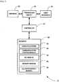
- FIG 2 is a block diagram illustrating the main components of the mobile device 3 shown in Figure 1 (e.g. a mobile telephone or other user equipment).
- the mobile device 3 has a transceiver circuit 31 that is operable to transmit signals to and to receive signals from a base station 5 via one or more antenna 33.
- the mobile device 3 has a controller 37 to control the operation of the mobile device 3.
- the controller 37 is associated with a memory 39 and is coupled to the transceiver circuit 31.
- the mobile device 3 might of course have all the usual functionality of a conventional mobile telephone 3 (such as a user interface 35) and this may be provided by any one or any combination of hardware, software and firmware, as appropriate.
- Software may be pre-installed in the memory 39 and/or may be downloaded via the telecommunications network or from a removable data storage device (RMD), for example.
- RMD removable data storage device
- the controller 37 is configured to control overall operation of the mobile device 3 by, in this example, program instructions or software instructions stored within the memory 39. As shown, these software instructions include, among other things, an operating system 41, a communications control module 43, an SSC module 44, a mobility module 45, and a cell measurement module 46.
- the communications control module 43 is operable to control the communication between the mobile device 3 and its serving base station 5 (and other communication devices connected to the serving base station 5, such as further mobile devices and/or network nodes).
- the SSC module 44 is responsible for managing session and service continuity for each PDU session that the mobile device 3 has with the network, based on a respective associated SSC mode.
- the SSC module 44 is configured to associate an appropriate SSC mode to each application that resides in the mobile device 3 and/or each application that requests a PDU session.
- the SSC mode may be associated to an application / PDU session based (predetermined) provisioned policy, information provided by the application (e.g. when requesting a new PDU session), and/or information provided by the network (e.g. when accepting the PDU session).
- the mobility module 45 is responsible for maintaining network attachment via an appropriate cell (of a base station 5) whilst the mobile device 3 is moving within the area covered by the communication network 1.
- the mobility module 45 maintains network attachment by performing a cell reselection and/or handover procedure in dependence on signal conditions and/or the like. It will be appreciated that the mobility module 45 may perform a cell reselection and/or handover procedure even when the mobile device 3 remains stationary, for example, due to changes in signal conditions, network load in the current cell, and/or the like.
- the mobility module 45 communicates with the serving base station 5 and/or core network nodes in order to exchange information relating to the network attachment (PDU session) of the mobile device 3, including for example: the type of IP address used; the SSC mode used; and information identifying the TUPF / TUPF area allocated to the mobile device 3.
- the cell measurement module 46 is responsible for obtaining signal quality measurements for cells in the vicinity of the mobile device 3 and to generate and provide associated cell measurement reports to the serving base station 5.
- the signal quality measurements and reporting is based on an appropriate measurement configuration provided by the serving base station 5.
- FIG 3 is a block diagram illustrating the main components of a base station 5 shown in Figure 1 .
- the base station 5 has a transceiver circuit 51 for transmitting signals to and for receiving signals from the communication devices (such as mobile devices 3 / user equipment) via one or more antenna 53, and a network interface 55 for transmitting signals to and for receiving signals from network nodes (e.g. an associated TUPF controller 6 and/or other nodes in the core network 7).
- the base station 5 has a controller 57 to control the operation of the base station 5.
- the controller 57 is associated with a memory 59. Software may be pre-installed in the memory 59 and/or may be downloaded via the telecommunications network 1 or from a removable data storage device (RMD), for example.
- RMD removable data storage device
- the controller 57 is configured to control the overall operation of the base station 5 by, in this example, program instructions or software instructions stored within the memory 59. As shown, these software instructions include, among other things, an operating system 61, a communications control module 63, an SSC module 64, and measurement configuration module 66.
- the communications control module 63 is operable to control the communication between the base station 5 and mobile devices 3 (user equipment) and other network entities that are connected to the base station 5.
- the communications control module 63 also controls the separate flows of downlink user traffic (via associated data radio bearers) and control data to be transmitted to communication devices associated with this base station 5 including, for example, control data for core network services and/or mobility of the mobile device 3.
- the SSC module 64 is responsible for maintaining a mapping database identifying a relationship among TUPF service areas, cells, and SSC modes (per UE and/or PDU session).
- the SSC module 64 is operable to provide this information to other modules when appropriate. For example, the SSC module 64 may inform the measurement configuration module 66 whether a neighbouring cell belongs to the same or a different TUPF serving area than the cell(s) operated by this base station 5.
- the measurement configuration module 66 is responsible for configuring mobile devices 3 for performing and reporting signal quality measurements for cells in the vicinity of the mobile devices 3 (e.g. cells operated by this base station 5 and/or cells operated by neighbouring base stations).
- the measurement configuration module 66 obtains signal quality measurements by generating and sending an measurement configuration to a particular mobile device 3 and by receiving an associated measurement report.
- the measurement report may be used, for example, when performing a mobility procedure involving the mobile device 3 that provided the report.
- the mobile device 3 and the base station 5 are described for ease of understanding as having a number of discrete modules (such as the communications control modules and the SSC modules). Whilst these modules may be provided in this way for certain applications, for example where an existing system has been modified to implement the invention, in other applications, for example in systems designed with the inventive features in mind from the outset, these modules may be built into the overall operating system or code and so these modules may not be discernible as discrete entities. These modules may also be implemented in software, hardware, firmware or a mix of these.
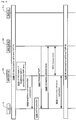
- Figure 4 is a timing diagram (message sequence chart) illustrating an example process performed by components of the system 1 when performing a mobility procedure between Cell A and Cell B.
- the mobile device 3 (using its mobility module 45) connects to Cell A (operated by base station 5A) which belongs to the serving area managed by the TUPF 6-1.
- the mobile device 3 (using its communications control module 43) initiates an appropriate PDU session towards the core network 7 (via the TUPF 6-1).
- the PDU session uses a nomadic IP address and SSC mode 2.
- the mobile device 3 (using its mobility module 45) obtains information identifying the TUPF 6-1 (and/or the TUPF service area) handling this PDU session, for example, from NAS signalling received from the core network 7 (or from the application that set up the PDU session).
- the mobile device 3 (using its mobility module 45) also informs its serving base station 5A about the type of IP address and SSC mode used for this PDU session (in this example, a nomadic IP address and SSC mode 2) and the TUPF / TUPF service area identifier.
- the type of IP address and SSC mode used for this PDU session in this example, a nomadic IP address and SSC mode 2
- the TUPF / TUPF service area identifier in this example, a nomadic IP address and SSC mode 2
- the serving base station 5A (using its SSC module 64) stores information identifying that the mobile device 3 is using SSC mode 2 and information identifying the TUPF 6-1 (TUPF area) for the PDU session.
- the serving base station 5A may not have any information on whether the neighbour cell (e.g. Cell B) belongs to the same TUPF serving area as the current cell (Cell A) of the mobile device 3.
- the serving base station 5A may store information identifying whether the neighbour cell (e.g. Cell B) belongs to the same or a different TUPF serving area as the current cell (Cell A) of the mobile device 3.
- the base station 5 is configured to treat the serving area of TUPF 6-1 as a single cell TUPF area (i.e. including the current Cell A only). Therefore, regardless whether or not the neighbour cell (in this example, Cell B) belongs to the same or a different TUPF serving area as the current cell (Cell A), the base station 5 is configured to initiate a redirection for the mobile device 3 when the mobile device 3 is moving to that neighbour cell.
- the neighbour cell in this example, Cell B
- Cell A the base station 5 is configured to initiate a redirection for the mobile device 3 when the mobile device 3 is moving to that neighbour cell.
- the base station 5 when the mobile device 3 is leaving the area served by Cell A, the base station 5 generates (using its communications control module 63) and sends, in step S103, an appropriate signalling message to the mobile device 3, including information about the neighbour cell (in this example, Cell B), which is the target serving cell for the mobile device 3.
- the information about the neighbour cell includes, for example, assistance information such as information identifying the target cell (e.g. a cell ID associated with Cell B), system information, and/or the like.
- assistance information such as information identifying the target cell (e.g. a cell ID associated with Cell B), system information, and/or the like.
- the base station 5 (using its measurement configuration module 66) may configure the mobile device 3 to carry out appropriate signal quality measurements and associated reporting (using its cell measurement module 46) before selecting a target cell.
- base station 5 may be configured to select the target cell based on the results of the cell measurements.
- step S105 the mobile device 3 performs cell reselection and, based on information broadcast (in step S107) by the new base station 5B (via Cell B), the mobile device 3 determines that the same TUPF 6-1 (and/or same TUPF service area) will continue handling the PDU session in the new Cell B (even though the mobile device 3 performs a redirection).
- the information broadcast by the new base station 5B may include the same information as the assistance information provided by the old base station in step S103. Accordingly, step S103 may be optional. The purpose of this information is to assist the mobile device 3 to camp on the new cell after cell reselection.
- step S109 the mobile device 3 generates and sends an appropriately formatted signalling message (e.g. an RRC message) for establishing a connection with the new serving base station 5B (operating Cell B).
- an appropriately formatted signalling message e.g. an RRC message
- the new serving base station 5B fetches, from the old serving base station 5A, the information (e.g. UE context) associated with the mobile device 3, and in step S113 the old base station 5A releases the mobile device's 3 connection via Cell A.
- connection release may take place at a later (or earlier) phase.
- the new base station 5B is able to continue serving the mobile device's 3 PDU session via its own cell (Cell B) and the mobile device 3 remains attached to the core network (i.e. it does not need to register again with the core network and establish a new PDU session).
- the information stored by the base station 5A (for Cell A) in S101 may be stored for later use (e.g. as described below with reference to Figure 5 ).
- the base station 5A may be configured to learn which neighbour cell belongs to which TUPF serving area and apply this knowledge when deciding whether to trigger handover (within the same TUPF area) or redirection (to a different TUPF area) during mobility of mobile devices 3 served by this base station 5A.
- Figure 5 is a timing diagram (message sequence chart) illustrating an example process performed by components of the system 1 when performing a mobility procedure between Cell A and Cell B.
- the serving base station 5A has information that the target cell (Cell B) belongs to the same TUPF serving area as the current cell (Cell A) of the mobile device 3.
- the base station 5A is aware of the mapping between the TUPF service area (similarly to tracking areas in LTE), SSC mode, and associated cell(s).
- a TUPF service area involves multiple cells (e.g. TUPF #1 serving area in Figure 1 )
- handover is permitted within the TUPF service area.
- redirection is performed (for example, as described above with reference to Figure 4 ).
- the mobile device 3 (using its mobility module 45) connects to Cell A (operated by base station 5A) which belongs to the serving area managed by the TUPF 6-1.
- Step S200 corresponds to step S100 of Figure 4 .
- the mobile device 3 initiates an appropriate PDU session towards the core network 7 (via the TUPF 6-1) using a nomadic IP address and SSC mode 2 (in this example).
- the mobile device 3 obtains information identifying the TUPF 6-1 (and/or the TUPF service area) handling this PDU session and informs its serving base station 5A about the type of IP address and SSC mode used for this PDU session and the TUPF / TUPF service area identifier.
- the serving base station 5A (using its SSC module 64) stores information identifying that the mobile device 3 is using SSC mode 2 and information identifying the TUPF 6-1 (TUPF area) for the PDU session.
- the serving base station 5A also stores information identifying that the neighbour cell (e.g. Cell B) belongs to the same TUPF serving area as the current cell (Cell A) of the mobile device 3. Accordingly, with respect to Cell B, the base station 5A is configured to perform handover instead of redirection.
- the base station 5A (using its measurement configuration module 66) configures the mobile device 3 to carry out appropriate signal quality measurements and associated reporting with respect to a set of neighbour cells (including Cell B).
- the mobile device 3 (using its cell measurement module 46) performs the configured signal quality measurements (for Cell B) and generates an appropriate measurement report.
- the mobile device 3 sends, in step S206, the generated measurement report (including measurement results for Cell B) to the base station 5A.
- the mobile device 3 also informs the serving base station 5A (e.g. in the message including the measurement report or in a similar message) if a particular cell is part of the same TUPF service area as the current cell (Cell A).
- each base station 5 may be configured to broadcast (or inform via dedicated signalling) to the mobile device 3 the TUPF service area(s) associated with its cell (s) and the mobile device 3 may be configured to determine if the current TUPF service area matches any of the TUPF service areas associated with neighbour cells (at least those cells for which the mobile device 3 is configured to perform measurements).
- the base station 5A is able to select an appropriate target cell for the mobile device 3 based on the results of the cell measurements and the information on whether a particular cell belongs to the same TUPF area as the current serving cell.
- the base station 5A selects Cell B (operated by base station 5B) as a handover target cell for the mobile device 3 (e.g. because Cell B is the best cell that meets the conditions for handover and it is within the same TUPF serving area as the current serving cell, Cell A). Therefore, the base station 5A (using its communications control module 63) generates and sends, in step S208, an appropriate signalling message to the base station 5B operating Cell B for handover preparation for the mobile device 3.
- step S213 the base station 5A (using its communications control module 63) generates and sends a signalling message instructing the mobile device 3 to initiate handover to Cell B. Therefore, after appropriate connection establishment with the new base station 5B, the mobile device 3 becomes connected to Cell B (step S215) and continues with its PDU session via the new base station 5B (in the same TUPF serving area).
- the old serving base station 5A can now proceed to perform an appropriate connection release or redirection procedure with the TUPF 6-1 as the base station 5A is no longer serving the mobile device 3.
- the TUPF entity is described as a stand-alone network node.
- the TUPF entity may be similar to the serving gateway (S-GW) in LTE although the TUPF may also have packet data network (PDN) gateway (P-GW) functionality.
- PDN packet data network gateway
- the TUPF may form part of an S-GW and/or a P-GW.
- a user-plane function other than a TUPF, but having similar functionality, may be used in place of the TUPF described herein.
- the mobile device informs the serving base station about the type of IP address and SSC mode used for the requested PDU session and an identifier of the TUPF / TUPF service area selected for this session.
- the base station may be configured to obtain such information from the core network (e.g. information identifying a mapping between TUPF service area and cells per SSC mode).
- the first and second base stations (Cells A and B) belong to a first TUPF service area and the third base station (Cell C) belongs to a second TUPF service area.
- the service are may be applicable for a particular UE (and/or a particular application) and different UEs (and/or different applications within the same UE) may have different associated TUPF serving areas.
- a particular application / UE may have a single TUPF service area throughout the entire network (e.g. Cells A, B, and C in Figure 1 ), whilst a different application / UE may have a different definition of TUPF service areas (e.g. Cell A in one TUPF area, and Cells B and C in a different TUPF area).
- the base stations may be configured to store and apply in their mobility decisions information identifying which cells can be used for handover and which cells can be used for redirection.
- This information may be stored per UE (subscription) and per service (optionally, per application).
- This information may beneficially allow flexible deployment of various applications with different needs (even though with the same SSC mode). For example, enterprise applications may be treated differently to personal applications within the same cell (and for the same mobile device).
- the radio access network may comprise a WLAN, for example, the WLAN shown in Figure 6 .
- the WLAN may have one or more cells (operated by one or more associated access points).
- the WLAN / access points may be connected to the 3GPP NextGen core network via an appropriate interface for communicating control plane and user-plane data between the NextGen core network and the WLAN (which acts as the NextGen RAN in this case).
- Each cell of the WLAN e.g. 'Cell W' operated by access point 5W
- some (or all) cells of the WLAN may be assigned to the same TUPF area. It will be appreciated that in this case the procedure described with reference to Figure 4 may apply (i.e. trigger redirection between cells that belong to the same TUPF area).
- a NAS layer may be provided on top of the WLAN layer / WLAN stack (e.g. in the WLAN chipset of the UE). Therefore, the WLAN chipset of the mobile device may be configured to communicate with the NextGen core network using appropriate NAS signalling.
- the NAS layer is responsible for mobility management (MM), session management (SM), and connection management (CM) for the mobile device, including session and service continuity (in the WLAN/RAN).
- MM mobility management
- SM session management
- CM connection management
- NAS layer security procedures may be used to authorise and authenticate any access RAT.
- On the network side security anchor and SM/MM entities may be different but from the mobile device point of view, a single NAS layer will be sufficient.
- WLAN security may be derived from 3GPP parameters, e.g. by providing an appropriate 'Kwt' key to the serving WLAN access point for authenticating the mobile device (e.g. when the mobile device first attaches to the WLAN). It will be appreciated that such Kwt key may be similar to (or the same as) the 'SKwt' key currently used in LTE-WLAN aggregation (LWA) for WLAN security.
- LWA LTE-WLAN aggregation
- the mobile device may beneficially use its WLAN connection (e.g. when it is simultaneously connected to the WLAN and a NexGen RAN) to indicate, to the core network, the occurrence of a radio link failure (RLF) on the RAN (or vice versa). This would allow better service continuity for the mobile device.
- WLAN connection e.g. when it is simultaneously connected to the WLAN and a NexGen RAN
- RLF radio link failure
- FIG 7 shows an exemplary control-plane (CP) and user-plane (UP) architecture.
- CP control-plane
- UP user-plane
- FIG. 7 shows an exemplary control-plane (CP) and user-plane (UP) architecture.
- CP control-plane
- UP user-plane
- an appropriate UP entity is provided at the edge of the RAN (denoted UP GA 12A).
- the UP entity may be used by the network operator for delivering push advertisements and/or other similar small data transmissions to mobile devices within the RAN (for example, re-using an existing RAN bearer for this purpose).
- such small data may be pushed from any other RAN entity (e.g. a router or aggregator or switch or the base station itself).
- WLAN has the possibility for push advertisements and web browsers display local contents (mainly advertisements). Therefore, the 5G RAN may be adapted to provide the same possibility.
- One option is to over provision the radio bearers (i.e. leave room for transmission of such push advertisements / small data on top of the data for which the radio bearer is set up). For example, if IP flow #1 is 5 MBPS (for a particular mobile device) and a corresponding radio bearer is configured with 5.5 MBPS (by the base station), then 0.5 MBPS can be used for transmitting local (push) content to that mobile device (over that radio bearer).
- the (push) content may be encrypted using the same security algorithm as normal data for this radio bearer (since the content is pushed on top of the PDCP layer in the base station).
- an appropriate mechanism may be provided to separate the packets received over such an over provisioned radio bearer.
- packets marked for the corresponding IP flow may be detected and (additional) local content may be pushed with the same destination address, using the over-provisioned portion of the radio bearer.
- a web browser running on the mobile device is able to publish/display the original content (requested by the mobile device itself) and any locally pushed content (e.g. push advertisements from the base station) so that no segregation of packets is needed in the UE access stratum (AS) or non-access stratum (NAS) layer.
- AS access stratum
- NAS non-access stratum
- an appropriate standalone radio bearer configuration (corresponding to no IP flow on the CN side) may be used instead of overprovisioning for locally generated packets.
- packets may be sent to the mobile devices without SM/MM entity involvement when using such a standalone radio bearer.
- this solution may be implemented in a router or a TNL aggregator node or any other node (e.g. a node which is not terminating any 3GPP protocols) sitting above the eNB in the network.
- the base station uses a 3GPP radio communications (radio access) technology to communicate with the mobile device.
- radio communications radio access
- any other radio communications technology i.e. WLAN, Wi-Fi, WiMAX, Bluetooth, etc.
- WLAN Wireless Fidelity
- Wi-Fi Wireless Fidelity
- WiMAX WiMAX
- Bluetooth Bluetooth
- the above example embodiments are also applicable to 'non-mobile' or generally stationary user equipment.
- the mobile device and the base station are described for ease of understanding as having a number of discrete functional components or modules. Whilst these modules may be provided in this way for certain applications, for example where an existing system has been modified to implement the invention, in other applications, for example in systems designed with the inventive features in mind from the outset, these modules may be built into the overall operating system or code and so these modules may not be discernible as discrete entities.
- the software modules may be provided in compiled or un-compiled form and may be supplied to the base station, to the mobility management entity, or to the mobile device as a signal over a computer network, or on a recording medium. Further, the functionality performed by part or all of this software may be performed using one or more dedicated hardware circuits. However, the use of software modules is preferred as it facilitates the updating of the base station or the mobile device in order to update their functionalities.
- the target cell may be associated with the same user-plane function serving area as the source cell operated by the base station and the controller of the base station may be able to determine that the user-plane function serving area that the target cell is associated with is the same as the user-plane function serving area that the source cell is associated with.
- the controller of the base station may be operable to initiate a handover procedure in which a communication connection for the communication session of the communication device via the source cell is not broken until a base station operating the target cell has been prepared to receive communication for the communication session of the communication device via the target cell.
- the controller of the base station may be operable to determine a session and service continuity (SSC) mode associated with the communication session for the communication device (for example, by determining whether the communication session requires an Internet Protocol, IP, session continuity and IP address reachability in the communication system over a predetermined user-plane function service area). For example, the controller may be operable to determine the SSC mode associated with the communication session for the communication device during establishment of the communication session.
- SSC session and service continuity
- the target cell may be associated with the same user-plane function serving area as the source cell operated by the base station, in which case the controller of the base station may be operable to initiate the redirection procedure when the controller determines that the SSC mode is a mode (e.g. SSC mode 2) in which the communication session uses a nomadic (or non-persistent) IP address (e.g. when the communication session does not require either IP session continuity or IP address reachability).
- SSC mode e.g. SSC mode 2
- IP address e.g. when the communication session does not require either IP session continuity or IP address reachability
- the controller of the base station may be operable to initiate a mobility procedure other than a redirection procedure when the controller determines that the SSC mode is a mode (e.g. SSC mode 1) in which the communication session uses a fixed (or persistent) IP address.
- SSC mode a mode in which the communication session uses a fixed (or persistent) IP address.
- the controller of the base station may be operable to maintain information identifying a mapping between SSC modes and user-plane function service areas and cells, and control mobility of the communication device based on the mapping.
- the target cell may be associated with the same user-plane function serving area as the source cell operated by the base station but the controller of the base station may be unable to determine that the user-plane function serving area that the target cell is associated with is the same as the user-plane function serving area that the source cell is associated with.
- the controller of the base station may be operable to initiate a redirection procedure, in which a communication connection for the communication session of the communication device via the source cell is broken before a base station operating the target cell has been prepared to receive communication for the communication session of the communication device via the target cell.
- the base station may comprise a base station of a 3GPP next generation (NextGen I 5G) radio access network.
- NextGen I 5G next generation
- the controller of the radio access network apparatus may be operable to encrypt both communication device requested data flow and the additional network initiated data flow using the same communication device specific security parameters.
- the communication device may further comprise: a transceiver for communicating, with a base station coupled to the core network, over an associated radio bearer; and a controller operable to detect a radio link failure, RLF, relating to the radio bearer; and the controller may be operable to provide, via the WLAN access point, an indication of the RLF to a node of the core network.
- a transceiver for communicating, with a base station coupled to the core network, over an associated radio bearer
- a controller operable to detect a radio link failure, RLF, relating to the radio bearer
- the controller may be operable to provide, via the WLAN access point, an indication of the RLF to a node of the core network.
Landscapes
- Engineering & Computer Science (AREA)
- Computer Networks & Wireless Communication (AREA)
- Signal Processing (AREA)
- Mobile Radio Communication Systems (AREA)
Claims (8)
- Basisstation (5B) für ein Kommunikationssystem (1), das mehrere Zellen umfasst, wobei jede der mehreren Zellen zu einer jeweiligen von mehreren Abschlussbenutzer-ebenenfunktions-, TUPF-, Dienstbereichen gehört, wobei die Basisstation (5B) aufweist:eine Steuerung (57) und einen Transceiver (51),wobei die Steuerung (57) konfiguriert ist, um eine Zuordnung zwischen den mehreren Zellen und den jeweiligen TUPF-Dienstbereichen zu speichern,wobei der Transceiver (51) konfiguriert ist, um, wenn eine Kommunikationsvorrichtung (3) sich mit einer ersten Zelle (B) verbindet, die durch die Basisstation (5B) betrieben wird, und eine Benutzerebenensitzung mit einer Abschlussbenutzerebenenfunktion, TUPF, einrichtet, von der Kommunikationsvorrichtung (3) erste Informationen, die eine Sitzungs- und Dienstkontinuitäts-, SSC-, Betriebsart spezifizieren, die in der Kommunikationssitzung verwendet wird, und die erste Zelle (B) identifizieren, zu empfangen,wobei der Transceiver (51) ferner konfiguriert ist, um, wenn die Kommunikationsvorrichtung (3) sich von der ersten Zelle (B) zu einer zweiten Zelle (C) bewegt, die von einer anderen Basisstation (5C) betrieben wird, von der Kommunikationsvorrichtung (3) zweite Informationen, welche die zweite Zelle (C) identifizieren, zu empfangen, und an die andere Basisstation (5C) und die Kommunikationsvorrichtung (3) eine Nachricht zu senden, die anweist, dass die Verbindungseinrichtung zwischen der anderen Basisstation (5C) und der Kommunikationsvorrichtung (3) eingeleitet werden soll,wobei die Steuerung (57) ferner konfiguriert ist, um basierend auf der Zuordnung zu bestimmen, ob die SSC-Betriebsart eine vorgegebene Betriebsart ist und ein erster TUPF-Dienstbereich (6-1), der zu der ersten Zelle (B) gehört, gleich wie ein zweiter TUPF-Dienstbereich (6-2) ist, der zu der zweiten Zelle (C) gehört, undwobei, wenn die SSC-Betriebsart die vorgegebene Betriebsart ist und der erste TUPF-Dienstbereich (6-1), wie durch die Zuordnung bestimmt, nicht gleich wie der zweite TUPF-Dienstbereich (6-2) ist, die Steuerung (57) ferner konfiguriert ist, um ein Umleitungsverfahren auszulösen, wodurch die Kommunikationsvorrichtung die Verbindung zu der Basisstation unterbricht und eine neue Verbindung zu der anderen Basisstation (5C) erzeugt, wodurch die Benutzerebenensitzung der Mobilvorrichtung mit der TUPF freigegeben wird und die Mobilvorrichtung eine neue Benutzerebenensitzung mit der zweiten TUPF (6-2) einleitet.
- Basisstation (5B) nach Anspruch 1, wobei, wenn die SSC-Betriebsart die vorgegebene Betriebsart ist und der erste TUPF-Dienstbereich (6-1) gleich dem zweiten TUPF-Dienstbereich (6-2) ist, die Steuerung (57) die Steuerung durchführt, um die Kommunikationsverbindung an die andere Basisstation (5A) weiterzugeben und die Kommunikationssitzung über die andere Basisstation (5A) fortzusetzen, ohne die Kommunikationssitzung zu trennen.
- Basisstation (5B) nach Anspruch 1 oder 2, wobei die vorgegebene Betriebsart eine Betriebsart ist, in der die Kommunikationssitzung eine nomadische oder nicht beständige IP-Adresse verwendet.
- Basisstation (5B) nach einem der Ansprüche 1 bis 3, wobei, wenn die SSC-Betriebsart eine Betriebsart ist, in der die Kommunikationssitzung eine feste oder beständige IP-Adresse verwendet, die Steuerung (57) steuert, um die Kommunikationsverbindung und die Kommunikationssitzung zu trennen und eine Kommunikationsverbindung und eine Kommunikationssitzung über die andere Basisstation einzurichten.
- Basisstation (5A) für ein Kommunikationssystem (1), das mehrere Zellen umfasst, wobei jede der mehreren Zellen zu einer jeweiligen von mehreren Abschlussbenutzer-ebenenfunktions-, TUPF-, Dienstbereichen gehört, wobei die Basisstation (5A) aufweist:eine Steuerung (57) und einen Transceiver (51),wobei die Steuerung (57) konfiguriert ist, um eine Zuordnung zwischen den mehreren Zellen und den jeweiligen TUPF-Dienstbereichen zu speichern,wobei der Transceiver (51) konfiguriert ist, um, wenn eine Kommunikationsvorrichtung (3) sich mit einer ersten Zelle (A) verbindet, die durch die Basisstation (5A) betrieben wird, und eine Benutzerbenensitzung mit einer Abschlussbenutzerebenenfunktion, TUPF-, einrichtet, von der Kommunikationsvorrichtung (3) erste Informationen, die eine Sitzungs- und Dienstkontinuitäts-, SSC-, Betriebsart spezifizieren, die in der Kommunikationssitzung verwendet wird, und die erste Zelle (A) identifizieren, zu empfangen,wobei der Transceiver (51) ferner konfiguriert ist, um, wenn die Kommunikationsvorrichtung (3) sich von der ersten Zelle (A) zu einer zweiten Zelle (B) bewegt, die von einer anderen Basisstation (5B) betrieben wird, von der Kommunikationsvorrichtung (3) zweite Informationen, welche die zweite Zelle (B) identifizieren, zu empfangen, und an die andere Basisstation (5B) und die Kommunikationsvorrichtung (3) eine Nachricht zu senden, die anweist, dass die Verbindungseinrichtung zwischen der anderen Basisstation (5B) und der Kommunikationsvorrichtung (3) eingeleitet werden soll,wobei die Steuerung (57) ferner konfiguriert ist, um basierend auf der Zuordnung zu bestimmen, ob die SSC-Betriebsart eine vorgegebene Betriebsart ist und ein erster TUPF-Dienstbereich (6-1), der zu der ersten Zelle (A) gehört, gleich wie ein zweiter TUPF-Dienstbereich (6-2) ist, der zu der zweiten Zelle (B) gehört, undwobei, wenn die SSC-Betriebsart die vorgegebene Betriebsart ist und der erste TUPF-Dienstbereich (6-1), wie durch die Zuordnung bestimmt, gleich wie der zweite TUPF-Dienstbereich (6-2) ist, die Steuerung (57) ferner konfiguriert ist, um eine Steuerung durchzuführen, um die Kommunikationsverbindung an die andere Basisstation (5B) weiterzugeben und die Benutzerebenensitzung mit der TUPF über die andere Basisstation (5B) fortzusetzen, ohne die Benutzerebenensitzung mit der TUPF zu trennen.
- Basisstation (5A) nach Anspruch 5, wobei, wenn die SSC-Betriebsart die vorgegebene Betriebsart ist und der erste TUPF-Dienstbereich (6-1) nicht gleich dem zweiten TUPF-Dienstbereich (6-2) ist, die Steuerung (57) ferner konfiguriert ist, um die Steuerung zum Trennen einer Verbindung mit der Kommunikationsvorrichtung (3) und der Kommunikationssitzung durchzuführen und eine Kommunikationssitzung über die andere Basisstation (5C) und eine Kommunikationsverbindung zwischen der anderen Basisstation (5C) und der Kommunikationsvorrichtung (3) einzurichten.
- Verfahren, das von einer Basisstation (5B) für ein Kommunikationssystem (1) durchgeführt wird, das mehrere Zellen umfasst, wobei jede der mehreren Zellen zu einer jeweiligen von mehreren Abschlussbenutzerebenenfunktions-, TUPF-, Dienstbereichen gehört, wobei das Verfahren aufweist:Speichern einer Zuordnung zwischen den mehreren Zellen und den jeweiligen TUPF-Dienstbereichen,Empfangen erster Informationen, die eine Sitzungs- und Dienstkontinuitäts-, SSC-, Betriebsart spezifizieren, die in der Kommunikationssitzung verwendet wird, und die erste Zelle (B) identifizieren, von der Kommunikationsvorrichtung (3), wenn eine Kommunikationsvorrichtung (3) sich mit einer ersten Zelle (B) verbindet, die durch die Basisstation (5B) betrieben wird, und eine Abschlussbenutzerebenenfunktion, TUPF-, einrichtet,Empfangen zweiter Informationen, welche die zweite Zelle (C) identifizieren, von der Kommunikationsvorrichtung (3), wenn die Kommunikationsvorrichtung (3) sich von der ersten Zelle (B) zu einer zweiten Zelle (C) bewegt, die von einer anderen Basisstation (5C) betrieben wird,Senden einer Nachricht, die anweist, dass die Verbindungseinrichtung zwischen der anderen Basisstation (5C) und der Kommunikationsvorrichtung (3) eingeleitet werden soll, an die andere Basisstation (5C) und die Kommunikationsvorrichtung (3),basierend auf der Zuordnung Bestimmen, ob die SSC-Betriebsart eine vorgegebene Betriebsart ist und ein erster TUPF-Dienstbereich (6-1), der zu der ersten Zelle (B) gehört, gleich wie ein zweiter TUPF-Dienstbereich (6-2) ist, der zu der zweiten Zelle (C) gehört, undDurchführen der Steuerung, um ein Umleitungsverfahren auszulösen, wodurch die Kommunikationsvorrichtung die Verbindung zu der Basisstation unterbricht und eine neue Verbindung zu der anderen Basisstation (5C) erzeugt, wodurch die Benutzerebenensitzung der Mobilvorrichtung mit der TUPF freigegeben wird und die Mobilvorrichtung eine neue Benutzerebenensitzung mit der zweiten TUPF (6-2) einleitet.
- Verfahren, das von einer Basisstation (5A) für ein Kommunikationssystem (1) durchgeführt wird, das mehrere Zellen umfasst, wobei jede der mehreren Zellen zu einer jeweiligen von mehreren Abschlussbenutzerebenenfunktions-, TUPF-, Dienstbereichen gehört, wobei das Verfahren aufweist:Speichern einer Zuordnung zwischen den mehreren Zellen und den jeweiligen TUPF-Dienstbereichen,Empfangen erster Informationen, die eine Sitzungs- und Dienstkontinuitäts-, SSC-, Betriebsart spezifizieren, die in der Kommunikationssitzung verwendet wird, und die erste Zelle (A) identifizieren, von der Kommunikationsvorrichtung (3), wenn eine Kommunikationsvorrichtung (3) sich mit einer ersten Zelle (A) verbindet, die durch die Basisstation (5A) betrieben wird, und eine Kommunikationssitzung einrichtet,Empfangen zweiter Informationen, welche die zweite Zelle (B) identifizieren, von der Kommunikationsvorrichtung (3), wenn die Kommunikationsvorrichtung (3) sich von der ersten Zelle (A) zu einer zweiten Zelle (B) bewegt, die von einer anderen Basisstation (5B) betrieben wird,Senden einer Nachricht, die anweist, dass die Verbindungseinrichtung zwischen der anderen Basisstation (5B) und der Kommunikationsvorrichtung (3) eingeleitet werden soll, an die andere Basisstation (5B) und die Kommunikationsvorrichtung (3),basierend auf der Zuordnung Bestimmen, ob die SSC-Betriebsart eine vorgegebene Betriebsart ist und ein erster TUPF-Dienstbereich (6-1), der zu der ersten Zelle (A) gehört, gleich wie ein zweiter TUPF-Dienstbereich (6-2) ist, der zu der zweiten Zelle (B) gehört, undDurchführen der Steuerung, um die Kommunikationsverbindung an die andere Basisstation (5B) weiterzugeben und die Kommunikationssitzung über die andere Basisstation (5B) fortzusetzen, ohne die Kommunikationssitzung zu trennen, wenn die SSC-Betriebsart die vorgegebene Betriebsart ist und der erste TUPF-Dienstbereich (6-1) gleich dem zweiten TUPF-Dienstbereich (6-2) ist.
Applications Claiming Priority (2)
| Application Number | Priority Date | Filing Date | Title |
|---|---|---|---|
| GB1613900.8A GB2552845A (en) | 2016-08-12 | 2016-08-12 | Communication system |
| PCT/JP2017/029060 WO2018030509A1 (en) | 2016-08-12 | 2017-08-10 | Mobility in 5g with handoff or cell reselection dependent on change of user-plane functionality serving area |
Publications (2)
| Publication Number | Publication Date |
|---|---|
| EP3497970A1 EP3497970A1 (de) | 2019-06-19 |
| EP3497970B1 true EP3497970B1 (de) | 2021-03-10 |
Family
ID=56985889
Family Applications (1)
| Application Number | Title | Priority Date | Filing Date |
|---|---|---|---|
| EP17757902.6A Active EP3497970B1 (de) | 2016-08-12 | 2017-08-10 | Mobilität in 5g mit übergabe oder zellenneuauswahl in abhängigkeit der veränderung des empfangsbereichs der benutzerebenenfunktionalität |
Country Status (7)
| Country | Link |
|---|---|
| US (1) | US11985551B2 (de) |
| EP (1) | EP3497970B1 (de) |
| JP (1) | JP6791358B2 (de) |
| CN (1) | CN109845323B (de) |
| GB (1) | GB2552845A (de) |
| RU (1) | RU2717562C1 (de) |
| WO (1) | WO2018030509A1 (de) |
Families Citing this family (14)
| Publication number | Priority date | Publication date | Assignee | Title |
|---|---|---|---|---|
| EP3479623B1 (de) * | 2016-07-01 | 2022-11-09 | IDAC Holdings, Inc. | Verfahren zur unterstützung der sitzungskontinuität auf sitzungsbasis |
| WO2018038490A1 (ko) | 2016-08-22 | 2018-03-01 | 삼성전자 주식회사 | 무선 통신 네트워크에서 지역별 데이터 네트워크 구성을 위한 방법 및 시스템 |
| EP3490333B1 (de) | 2016-08-22 | 2023-06-28 | Samsung Electronics Co., Ltd. | Verfahren und system zur konfiguration eines regionalen datennetzwerks in drahtloskommunikationsnetzwerk |
| JP2019208089A (ja) * | 2016-10-07 | 2019-12-05 | シャープ株式会社 | 端末装置、MME(Mobility Management Entity)、CPF(Control Plane Function)、及び通信制御方法 |
| JP2020036055A (ja) * | 2017-01-05 | 2020-03-05 | シャープ株式会社 | 端末装置、コアネットワーク装置、及び通信制御方法 |
| EP3569033B1 (de) * | 2017-02-01 | 2023-08-30 | Huawei Technologies Co., Ltd. | Sitzungstypfunktionseinheit, steuerungsebenenfunktionseinheit, verfahren und computerprogramm zur sitzungsverwaltung in mobilkernnetzwerken der nächsten generation |
| US10952176B2 (en) * | 2017-03-17 | 2021-03-16 | Samsung Electronics Co., Ltd. | AF influenced PDU session management and subscription procedures |
| EP3637683A4 (de) | 2017-05-09 | 2020-05-06 | Huawei Technologies Co., Ltd. | Sitzungsverwaltungsverfahren, endgerät und system |
| KR102434074B1 (ko) * | 2017-08-14 | 2022-08-22 | 삼성전자 주식회사 | 5g 셀룰러망의 로컬 오프로딩을 위한 앵커 upf 처리 방안 |
| EP3570585B1 (de) * | 2018-05-18 | 2020-10-14 | Ntt Docomo, Inc. | Klebrigkeit-entfernung von transaktionen in einem 5g netzwerk |
| EP3857998A1 (de) * | 2018-09-27 | 2021-08-04 | FRAUNHOFER-GESELLSCHAFT zur Förderung der angewandten Forschung e.V. | Standortverwaltung mit dynamischer tal für hohe mobilität |
| US20230345311A1 (en) * | 2020-02-18 | 2023-10-26 | Telefonaktiebolaget Lm Ericsson (Publ) | Technique for Performing a Context Transfer |
| CN113498126A (zh) * | 2020-04-01 | 2021-10-12 | 中兴通讯股份有限公司 | 非激活状态终端的小区重选方法、基站和计算机可读介质 |
| CN114189853B (zh) * | 2020-08-24 | 2023-12-12 | 海能达通信股份有限公司 | 一种终端的通信控制方法、装置及epc |
Family Cites Families (26)
| Publication number | Priority date | Publication date | Assignee | Title |
|---|---|---|---|---|
| US7444150B2 (en) * | 2003-10-08 | 2008-10-28 | Qualcomm Incorporated | Cell reselection with power scan and parallel decoding |
| US9049629B2 (en) | 2007-06-18 | 2015-06-02 | Qualcomm Incorporated | Method and apparatus for fast inter-system handover |
| US8467786B2 (en) * | 2009-05-04 | 2013-06-18 | Motorola Mobility Llc | Communication devices and methods for providing services to communication devices in a communication system including a private cell |
| US8412188B2 (en) | 2010-01-27 | 2013-04-02 | Qualcomm Incorporated | Managing session information in a wireless communications system |
| WO2011098249A2 (en) * | 2010-02-12 | 2011-08-18 | Nec Europe Ltd. | Method for supporting selection of pdn connections for a mobile terminal and mobile terminal |
| US8838106B2 (en) * | 2010-02-23 | 2014-09-16 | Apple Inc. | Method and apparatus for cell reselection |
| US9112683B2 (en) * | 2010-05-27 | 2015-08-18 | Maple Acquisition Llc | Maintaining triggered session state in secure user plane location (SUPL) enabled system |
| KR20130079564A (ko) * | 2010-09-28 | 2013-07-10 | 리서치 인 모션 리미티드 | Ue가 주택/기업 네트워크 커버리지 밖으로 이동할 때 로컬 gw와의 연결을 해제시키는 방법 및 장치 |
| WO2012073940A1 (ja) * | 2010-12-01 | 2012-06-07 | シャープ株式会社 | 通信システムおよび通信方法 |
| CN102695234A (zh) * | 2011-03-25 | 2012-09-26 | 中兴通讯股份有限公司 | 业务承载迁移方法及装置 |
| KR101581146B1 (ko) * | 2011-11-04 | 2015-12-29 | 엘지전자 주식회사 | 무선 통신 시스템에서 있어서 회선 교환 서비스를 위한 통신 방법 및 이를 지원하는 장치 |
| US9055560B2 (en) * | 2012-01-18 | 2015-06-09 | Mediatek Inc. | Method of enhanced connection recovery and loss-less data recovery |
| CN103841607A (zh) * | 2012-11-21 | 2014-06-04 | 中兴通讯股份有限公司 | 一种网关重定位的方法、移动管理实体及宿主基站 |
| CN104105143B (zh) * | 2013-04-03 | 2020-04-24 | 北京三星通信技术研究有限公司 | 一种支持sipto业务的方法 |
| JP6460102B2 (ja) * | 2014-06-24 | 2019-01-30 | 日本電気株式会社 | コントロールノード及びネットワークノード並びにこれらにより行われる方法 |
| US10313916B2 (en) * | 2014-11-11 | 2019-06-04 | Qualcomm Incorporated | Selected IP flow ultra low latency |
| WO2016107886A1 (en) * | 2014-12-30 | 2016-07-07 | British Telecommunications Public Limited Company | Celular handover |
| US11375372B2 (en) * | 2015-01-28 | 2022-06-28 | Telefonaktiebolaget L M Ericsson (Publ) | Method and nodes for handling a user equipment's access to a mobile communications network |
| JP6554177B2 (ja) * | 2015-03-27 | 2019-07-31 | テレフオンアクチーボラゲット エルエム エリクソン(パブル) | ネットワークへのueのアクセスを取り扱うための方法及びノード |
| US10321358B2 (en) * | 2015-05-22 | 2019-06-11 | Lg Electronics Inc. | Method for transmitting and receiving data in wireless communication system, and device therefor |
| US10645528B2 (en) * | 2015-09-18 | 2020-05-05 | Huawei Technologies Co., Ltd. | System and methods for reliable communication with mobility along a predictable route |
| US10638391B2 (en) * | 2015-11-02 | 2020-04-28 | Telefonaktiebolaget Lm Ericsson (Publ) | Method and apparatus for controlling selection of the solution for WLAN and unlicensed spectrum usage |
| US10142994B2 (en) * | 2016-04-18 | 2018-11-27 | Electronics And Telecommunications Research Institute | Communication method and apparatus using network slicing |
| EP3479623B1 (de) * | 2016-07-01 | 2022-11-09 | IDAC Holdings, Inc. | Verfahren zur unterstützung der sitzungskontinuität auf sitzungsbasis |
| WO2018006936A1 (en) * | 2016-07-04 | 2018-01-11 | Telefonaktiebolaget Lm Ericsson (Publ) | Technique for internet protocol anchor relocation |
| CN107592331B (zh) * | 2016-07-08 | 2021-11-02 | 中兴通讯股份有限公司 | 会话连续的实现方法、装置及系统 |
-
2016
- 2016-08-12 GB GB1613900.8A patent/GB2552845A/en not_active Withdrawn
-
2017
- 2017-08-10 RU RU2019106643A patent/RU2717562C1/ru active
- 2017-08-10 US US16/324,756 patent/US11985551B2/en active Active
- 2017-08-10 CN CN201780063104.9A patent/CN109845323B/zh active Active
- 2017-08-10 EP EP17757902.6A patent/EP3497970B1/de active Active
- 2017-08-10 WO PCT/JP2017/029060 patent/WO2018030509A1/en unknown
- 2017-08-10 JP JP2019507357A patent/JP6791358B2/ja active Active
Non-Patent Citations (1)
| Title |
|---|
| None * |
Also Published As
| Publication number | Publication date |
|---|---|
| JP2019528018A (ja) | 2019-10-03 |
| GB201613900D0 (en) | 2016-09-28 |
| RU2717562C1 (ru) | 2020-03-24 |
| WO2018030509A1 (en) | 2018-02-15 |
| CN109845323B (zh) | 2021-07-09 |
| US11985551B2 (en) | 2024-05-14 |
| US20190182723A1 (en) | 2019-06-13 |
| EP3497970A1 (de) | 2019-06-19 |
| CN109845323A (zh) | 2019-06-04 |
| GB2552845A (en) | 2018-02-14 |
| JP6791358B2 (ja) | 2020-11-25 |
Similar Documents
| Publication | Publication Date | Title |
|---|---|---|
| EP3497970B1 (de) | Mobilität in 5g mit übergabe oder zellenneuauswahl in abhängigkeit der veränderung des empfangsbereichs der benutzerebenenfunktionalität | |
| JP7044181B2 (ja) | 制御プレーンCIoT EPS最適化による負荷制御 | |
| CN109673174B (zh) | 以逐个会话为基础支持会话连续性的方法 | |
| US11153788B2 (en) | Handover method and user equipment | |
| US10631356B2 (en) | Communication apparatus, core network node, system, computer program and methods for rerouting NAS-messages | |
| CN107925932B (zh) | Lte-wlan聚合切换期间的控制和用户计划的划分方法、通信设备和通信装置 | |
| US8755312B2 (en) | Apparatus and method for supporting gateway node reselection in communication system | |
| US11330514B2 (en) | Communications system | |
| US20190394712A1 (en) | Network event reporting for pdn connectivity | |
| CN112313980A (zh) | 动态rfsp | |
| WO2019024767A1 (zh) | 释放ip地址的方法、装置、网络设备及系统 | |
| GB2509975A (en) | PDN service rejection | |
| CN108307691B (zh) | 通信系统 | |
| US11641602B2 (en) | Systems and methods for handover of dual connectivity user equipment | |
| US20230337087A1 (en) | Re-anchoring with smf re-selection | |
| US20220279397A1 (en) | Controlling network access for user equipment | |
| EP3984279A1 (de) | Handhabung von benutzergeräten in verbundenen cm-zustand mit inaktivem rrc-zustand | |
| CN117837208A (zh) | 一种在会话管理功能故障和重新选择之后的会话更新的方法 |
Legal Events
| Date | Code | Title | Description |
|---|---|---|---|
| STAA | Information on the status of an ep patent application or granted ep patent |
Free format text: STATUS: UNKNOWN |
|
| STAA | Information on the status of an ep patent application or granted ep patent |
Free format text: STATUS: THE INTERNATIONAL PUBLICATION HAS BEEN MADE |
|
| PUAI | Public reference made under article 153(3) epc to a published international application that has entered the european phase |
Free format text: ORIGINAL CODE: 0009012 |
|
| STAA | Information on the status of an ep patent application or granted ep patent |
Free format text: STATUS: REQUEST FOR EXAMINATION WAS MADE |
|
| 17P | Request for examination filed |
Effective date: 20190311 |
|
| AK | Designated contracting states |
Kind code of ref document: A1 Designated state(s): AL AT BE BG CH CY CZ DE DK EE ES FI FR GB GR HR HU IE IS IT LI LT LU LV MC MK MT NL NO PL PT RO RS SE SI SK SM TR |
|
| AX | Request for extension of the european patent |
Extension state: BA ME |
|
| STAA | Information on the status of an ep patent application or granted ep patent |
Free format text: STATUS: EXAMINATION IS IN PROGRESS |
|
| 17Q | First examination report despatched |
Effective date: 20190920 |
|
| DAV | Request for validation of the european patent (deleted) | ||
| DAX | Request for extension of the european patent (deleted) | ||
| GRAP | Despatch of communication of intention to grant a patent |
Free format text: ORIGINAL CODE: EPIDOSNIGR1 |
|
| STAA | Information on the status of an ep patent application or granted ep patent |
Free format text: STATUS: GRANT OF PATENT IS INTENDED |
|
| INTG | Intention to grant announced |
Effective date: 20200416 |
|
| GRAJ | Information related to disapproval of communication of intention to grant by the applicant or resumption of examination proceedings by the epo deleted |
Free format text: ORIGINAL CODE: EPIDOSDIGR1 |
|
| STAA | Information on the status of an ep patent application or granted ep patent |
Free format text: STATUS: EXAMINATION IS IN PROGRESS |
|
| INTC | Intention to grant announced (deleted) | ||
| GRAP | Despatch of communication of intention to grant a patent |
Free format text: ORIGINAL CODE: EPIDOSNIGR1 |
|
| STAA | Information on the status of an ep patent application or granted ep patent |
Free format text: STATUS: GRANT OF PATENT IS INTENDED |
|
| INTG | Intention to grant announced |
Effective date: 20200928 |
|
| GRAS | Grant fee paid |
Free format text: ORIGINAL CODE: EPIDOSNIGR3 |
|
| GRAA | (expected) grant |
Free format text: ORIGINAL CODE: 0009210 |
|
| STAA | Information on the status of an ep patent application or granted ep patent |
Free format text: STATUS: THE PATENT HAS BEEN GRANTED |
|
| AK | Designated contracting states |
Kind code of ref document: B1 Designated state(s): AL AT BE BG CH CY CZ DE DK EE ES FI FR GB GR HR HU IE IS IT LI LT LU LV MC MK MT NL NO PL PT RO RS SE SI SK SM TR |
|
| REG | Reference to a national code |
Ref country code: GB Ref legal event code: FG4D |
|
| REG | Reference to a national code |
Ref country code: AT Ref legal event code: REF Ref document number: 1371226 Country of ref document: AT Kind code of ref document: T Effective date: 20210315 Ref country code: CH Ref legal event code: EP |
|
| REG | Reference to a national code |
Ref country code: IE Ref legal event code: FG4D |
|
| REG | Reference to a national code |
Ref country code: DE Ref legal event code: R096 Ref document number: 602017034366 Country of ref document: DE |
|
| REG | Reference to a national code |
Ref country code: LT Ref legal event code: MG9D |
|
| PG25 | Lapsed in a contracting state [announced via postgrant information from national office to epo] |
Ref country code: NO Free format text: LAPSE BECAUSE OF FAILURE TO SUBMIT A TRANSLATION OF THE DESCRIPTION OR TO PAY THE FEE WITHIN THE PRESCRIBED TIME-LIMIT Effective date: 20210610 Ref country code: GR Free format text: LAPSE BECAUSE OF FAILURE TO SUBMIT A TRANSLATION OF THE DESCRIPTION OR TO PAY THE FEE WITHIN THE PRESCRIBED TIME-LIMIT Effective date: 20210611 Ref country code: FI Free format text: LAPSE BECAUSE OF FAILURE TO SUBMIT A TRANSLATION OF THE DESCRIPTION OR TO PAY THE FEE WITHIN THE PRESCRIBED TIME-LIMIT Effective date: 20210310 Ref country code: HR Free format text: LAPSE BECAUSE OF FAILURE TO SUBMIT A TRANSLATION OF THE DESCRIPTION OR TO PAY THE FEE WITHIN THE PRESCRIBED TIME-LIMIT Effective date: 20210310 Ref country code: BG Free format text: LAPSE BECAUSE OF FAILURE TO SUBMIT A TRANSLATION OF THE DESCRIPTION OR TO PAY THE FEE WITHIN THE PRESCRIBED TIME-LIMIT Effective date: 20210610 Ref country code: LT Free format text: LAPSE BECAUSE OF FAILURE TO SUBMIT A TRANSLATION OF THE DESCRIPTION OR TO PAY THE FEE WITHIN THE PRESCRIBED TIME-LIMIT Effective date: 20210310 |
|
| REG | Reference to a national code |
Ref country code: AT Ref legal event code: MK05 Ref document number: 1371226 Country of ref document: AT Kind code of ref document: T Effective date: 20210310 |
|
| REG | Reference to a national code |
Ref country code: NL Ref legal event code: MP Effective date: 20210310 |
|
| PG25 | Lapsed in a contracting state [announced via postgrant information from national office to epo] |
Ref country code: RS Free format text: LAPSE BECAUSE OF FAILURE TO SUBMIT A TRANSLATION OF THE DESCRIPTION OR TO PAY THE FEE WITHIN THE PRESCRIBED TIME-LIMIT Effective date: 20210310 Ref country code: LV Free format text: LAPSE BECAUSE OF FAILURE TO SUBMIT A TRANSLATION OF THE DESCRIPTION OR TO PAY THE FEE WITHIN THE PRESCRIBED TIME-LIMIT Effective date: 20210310 Ref country code: SE Free format text: LAPSE BECAUSE OF FAILURE TO SUBMIT A TRANSLATION OF THE DESCRIPTION OR TO PAY THE FEE WITHIN THE PRESCRIBED TIME-LIMIT Effective date: 20210310 |
|
| PG25 | Lapsed in a contracting state [announced via postgrant information from national office to epo] |
Ref country code: NL Free format text: LAPSE BECAUSE OF FAILURE TO SUBMIT A TRANSLATION OF THE DESCRIPTION OR TO PAY THE FEE WITHIN THE PRESCRIBED TIME-LIMIT Effective date: 20210310 |
|
| PG25 | Lapsed in a contracting state [announced via postgrant information from national office to epo] |
Ref country code: CZ Free format text: LAPSE BECAUSE OF FAILURE TO SUBMIT A TRANSLATION OF THE DESCRIPTION OR TO PAY THE FEE WITHIN THE PRESCRIBED TIME-LIMIT Effective date: 20210310 Ref country code: EE Free format text: LAPSE BECAUSE OF FAILURE TO SUBMIT A TRANSLATION OF THE DESCRIPTION OR TO PAY THE FEE WITHIN THE PRESCRIBED TIME-LIMIT Effective date: 20210310 Ref country code: AT Free format text: LAPSE BECAUSE OF FAILURE TO SUBMIT A TRANSLATION OF THE DESCRIPTION OR TO PAY THE FEE WITHIN THE PRESCRIBED TIME-LIMIT Effective date: 20210310 Ref country code: SM Free format text: LAPSE BECAUSE OF FAILURE TO SUBMIT A TRANSLATION OF THE DESCRIPTION OR TO PAY THE FEE WITHIN THE PRESCRIBED TIME-LIMIT Effective date: 20210310 |
|
| PG25 | Lapsed in a contracting state [announced via postgrant information from national office to epo] |
Ref country code: IS Free format text: LAPSE BECAUSE OF FAILURE TO SUBMIT A TRANSLATION OF THE DESCRIPTION OR TO PAY THE FEE WITHIN THE PRESCRIBED TIME-LIMIT Effective date: 20210710 Ref country code: RO Free format text: LAPSE BECAUSE OF FAILURE TO SUBMIT A TRANSLATION OF THE DESCRIPTION OR TO PAY THE FEE WITHIN THE PRESCRIBED TIME-LIMIT Effective date: 20210310 Ref country code: SK Free format text: LAPSE BECAUSE OF FAILURE TO SUBMIT A TRANSLATION OF THE DESCRIPTION OR TO PAY THE FEE WITHIN THE PRESCRIBED TIME-LIMIT Effective date: 20210310 Ref country code: PT Free format text: LAPSE BECAUSE OF FAILURE TO SUBMIT A TRANSLATION OF THE DESCRIPTION OR TO PAY THE FEE WITHIN THE PRESCRIBED TIME-LIMIT Effective date: 20210712 Ref country code: PL Free format text: LAPSE BECAUSE OF FAILURE TO SUBMIT A TRANSLATION OF THE DESCRIPTION OR TO PAY THE FEE WITHIN THE PRESCRIBED TIME-LIMIT Effective date: 20210310 |
|
| REG | Reference to a national code |
Ref country code: DE Ref legal event code: R097 Ref document number: 602017034366 Country of ref document: DE |
|
| PLBE | No opposition filed within time limit |
Free format text: ORIGINAL CODE: 0009261 |
|
| STAA | Information on the status of an ep patent application or granted ep patent |
Free format text: STATUS: NO OPPOSITION FILED WITHIN TIME LIMIT |
|
| PG25 | Lapsed in a contracting state [announced via postgrant information from national office to epo] |
Ref country code: ES Free format text: LAPSE BECAUSE OF FAILURE TO SUBMIT A TRANSLATION OF THE DESCRIPTION OR TO PAY THE FEE WITHIN THE PRESCRIBED TIME-LIMIT Effective date: 20210310 Ref country code: DK Free format text: LAPSE BECAUSE OF FAILURE TO SUBMIT A TRANSLATION OF THE DESCRIPTION OR TO PAY THE FEE WITHIN THE PRESCRIBED TIME-LIMIT Effective date: 20210310 Ref country code: AL Free format text: LAPSE BECAUSE OF FAILURE TO SUBMIT A TRANSLATION OF THE DESCRIPTION OR TO PAY THE FEE WITHIN THE PRESCRIBED TIME-LIMIT Effective date: 20210310 |
|
| 26N | No opposition filed |
Effective date: 20211213 |
|
| PG25 | Lapsed in a contracting state [announced via postgrant information from national office to epo] |
Ref country code: SI Free format text: LAPSE BECAUSE OF FAILURE TO SUBMIT A TRANSLATION OF THE DESCRIPTION OR TO PAY THE FEE WITHIN THE PRESCRIBED TIME-LIMIT Effective date: 20210310 |
|
| REG | Reference to a national code |
Ref country code: CH Ref legal event code: PL |
|
| PG25 | Lapsed in a contracting state [announced via postgrant information from national office to epo] |
Ref country code: MC Free format text: LAPSE BECAUSE OF FAILURE TO SUBMIT A TRANSLATION OF THE DESCRIPTION OR TO PAY THE FEE WITHIN THE PRESCRIBED TIME-LIMIT Effective date: 20210310 |
|
| REG | Reference to a national code |
Ref country code: BE Ref legal event code: MM Effective date: 20210831 |
|
| GBPC | Gb: european patent ceased through non-payment of renewal fee |
Effective date: 20210810 |
|
| PG25 | Lapsed in a contracting state [announced via postgrant information from national office to epo] |
Ref country code: LI Free format text: LAPSE BECAUSE OF NON-PAYMENT OF DUE FEES Effective date: 20210831 Ref country code: IT Free format text: LAPSE BECAUSE OF FAILURE TO SUBMIT A TRANSLATION OF THE DESCRIPTION OR TO PAY THE FEE WITHIN THE PRESCRIBED TIME-LIMIT Effective date: 20210310 Ref country code: CH Free format text: LAPSE BECAUSE OF NON-PAYMENT OF DUE FEES Effective date: 20210831 |
|
| PG25 | Lapsed in a contracting state [announced via postgrant information from national office to epo] |
Ref country code: IS Free format text: LAPSE BECAUSE OF FAILURE TO SUBMIT A TRANSLATION OF THE DESCRIPTION OR TO PAY THE FEE WITHIN THE PRESCRIBED TIME-LIMIT Effective date: 20210710 Ref country code: LU Free format text: LAPSE BECAUSE OF NON-PAYMENT OF DUE FEES Effective date: 20210810 |
|
| PG25 | Lapsed in a contracting state [announced via postgrant information from national office to epo] |
Ref country code: IE Free format text: LAPSE BECAUSE OF NON-PAYMENT OF DUE FEES Effective date: 20210810 Ref country code: GB Free format text: LAPSE BECAUSE OF NON-PAYMENT OF DUE FEES Effective date: 20210810 Ref country code: FR Free format text: LAPSE BECAUSE OF NON-PAYMENT OF DUE FEES Effective date: 20210831 Ref country code: BE Free format text: LAPSE BECAUSE OF NON-PAYMENT OF DUE FEES Effective date: 20210831 |
|
| PG25 | Lapsed in a contracting state [announced via postgrant information from national office to epo] |
Ref country code: CY Free format text: LAPSE BECAUSE OF FAILURE TO SUBMIT A TRANSLATION OF THE DESCRIPTION OR TO PAY THE FEE WITHIN THE PRESCRIBED TIME-LIMIT Effective date: 20210310 |
|
| PG25 | Lapsed in a contracting state [announced via postgrant information from national office to epo] |
Ref country code: HU Free format text: LAPSE BECAUSE OF FAILURE TO SUBMIT A TRANSLATION OF THE DESCRIPTION OR TO PAY THE FEE WITHIN THE PRESCRIBED TIME-LIMIT; INVALID AB INITIO Effective date: 20170810 |
|
| PGFP | Annual fee paid to national office [announced via postgrant information from national office to epo] |
Ref country code: DE Payment date: 20230821 Year of fee payment: 7 |
|
| PG25 | Lapsed in a contracting state [announced via postgrant information from national office to epo] |
Ref country code: MK Free format text: LAPSE BECAUSE OF FAILURE TO SUBMIT A TRANSLATION OF THE DESCRIPTION OR TO PAY THE FEE WITHIN THE PRESCRIBED TIME-LIMIT Effective date: 20210310 |