EP3497503B1 - Am körper tragbare augennahe sichtsysteme mit grosser austrittspupille und ausnutzung von freiformokularen - Google Patents
Am körper tragbare augennahe sichtsysteme mit grosser austrittspupille und ausnutzung von freiformokularen Download PDFInfo
- Publication number
- EP3497503B1 EP3497503B1 EP17838242.0A EP17838242A EP3497503B1 EP 3497503 B1 EP3497503 B1 EP 3497503B1 EP 17838242 A EP17838242 A EP 17838242A EP 3497503 B1 EP3497503 B1 EP 3497503B1
- Authority
- EP
- European Patent Office
- Prior art keywords
- free
- lens
- prism
- user
- form surface
- Prior art date
- Legal status (The legal status is an assumption and is not a legal conclusion. Google has not performed a legal analysis and makes no representation as to the accuracy of the status listed.)
- Active
Links
Images


Classifications
-
- G—PHYSICS
- G02—OPTICS
- G02B—OPTICAL ELEMENTS, SYSTEMS OR APPARATUS
- G02B27/00—Optical systems or apparatus not provided for by any of the groups G02B1/00 - G02B26/00, G02B30/00
- G02B27/01—Head-up displays
- G02B27/017—Head mounted
- G02B27/0172—Head mounted characterised by optical features
-
- G—PHYSICS
- G06—COMPUTING OR CALCULATING; COUNTING
- G06F—ELECTRIC DIGITAL DATA PROCESSING
- G06F1/00—Details not covered by groups G06F3/00 - G06F13/00 and G06F21/00
- G06F1/16—Constructional details or arrangements
- G06F1/1613—Constructional details or arrangements for portable computers
- G06F1/163—Wearable computers, e.g. on a belt
-
- G—PHYSICS
- G02—OPTICS
- G02B—OPTICAL ELEMENTS, SYSTEMS OR APPARATUS
- G02B27/00—Optical systems or apparatus not provided for by any of the groups G02B1/00 - G02B26/00, G02B30/00
- G02B27/01—Head-up displays
- G02B27/0101—Head-up displays characterised by optical features
- G02B2027/0123—Head-up displays characterised by optical features comprising devices increasing the field of view
-
- G—PHYSICS
- G02—OPTICS
- G02B—OPTICAL ELEMENTS, SYSTEMS OR APPARATUS
- G02B27/00—Optical systems or apparatus not provided for by any of the groups G02B1/00 - G02B26/00, G02B30/00
- G02B27/01—Head-up displays
- G02B27/017—Head mounted
- G02B2027/0178—Eyeglass type
-
- G—PHYSICS
- G02—OPTICS
- G02B—OPTICAL ELEMENTS, SYSTEMS OR APPARATUS
- G02B27/00—Optical systems or apparatus not provided for by any of the groups G02B1/00 - G02B26/00, G02B30/00
- G02B27/01—Head-up displays
- G02B27/0179—Display position adjusting means not related to the information to be displayed
- G02B2027/0187—Display position adjusting means not related to the information to be displayed slaved to motion of at least a part of the body of the user, e.g. head, eye
-
- G—PHYSICS
- G02—OPTICS
- G02B—OPTICAL ELEMENTS, SYSTEMS OR APPARATUS
- G02B27/00—Optical systems or apparatus not provided for by any of the groups G02B1/00 - G02B26/00, G02B30/00
- G02B27/01—Head-up displays
- G02B27/0179—Display position adjusting means not related to the information to be displayed
Definitions
- This invention relates to wearable near-to-eye (NR21) vision systems and more particularly to providing wearable NR2I vision systems with wide field of view, high image resolution, large exit pupil for eye placement, sufficient eye clearance, and elegant ergonomic design.
- NR21 near-to-eye
- NR21 vision systems or NR21 displays are a class of wearable device that creates a display in front of the user's field of vision from an electronic display.
- the display may be transparent such that the viewer can view the external world and the projected electronic display simultaneously or opaque wherein the viewer may directly view the electronic display or a projected electronic display, depending on the application.
- a transparent display can overlay information and graphics on top on the real world, while an opaque display can provide an immersive theater-like experience.
- Further NR21 displays may provide information within the full visual field of view of the user or may alternatively provide information within part of the user's field of view.
- NR21 displays can be broadly placed in two categories, immersive and see-through.
- Immersive NR21 displays block a user's view of the real world and create a large field of view image, typically 30°-60° for cinema glasses and 90° or more for virtual reality displays.
- See-through NR21 displays leave the user's view of the real world open and create either a transparent image or a very small opaque image that blocks only a small portion of the user's peripheral vision.
- the see-through category can be further broken down into two applications, augmented reality and smart glasses.
- Augmented reality headsets typically offer 20°-60° fields of view and overlay information and graphics on top of the user's view of the real world.
- Smart glasses which is really a misnomer, in contrast typically have a smaller field of view and a display which the user glances at periodically rather than looking through the display continuously.
- NR2I displays For users exploiting NR2I displays for augmented reality and / or correction of low vision, then the user is typically, either going to wear the NR2I displays for specific tasks, for specific visual environments, etc. and hence there is an issue of repeatedly attaching and removing the NR2I display or they are going to be wearing the NR2I display for extended periods of time, potentially all their time awake. Accordingly, the majority of applications irrespective of whether they are for short-term, long-term, low vision, augmented reality, etc.
- An aspect of the invention provides a near-to-eye (NR2I) display system comprising the features of claim 1.
- NR2I near-to-eye
- the first surface of the first free-form prism-lens may be defined by a surface that is at least one of non- rotationally symmetric and has non-symmetric features and is configured to transmit the received light from the first microdisplay into the body of the first free-form prism-lens and towards a second surface of said first free-form prism-lens;
- the second surface of the first free-form prism-lens may be defined by a surface that is at least one of non-rotationally symmetric and has non-symmetric features and is configured to internally reflect over a first portion of the second surface light from the first microdisplay entering the first free-form prism-lens through the first surface towards a third surface of the first freeform prism-lens and configured to transmit over a second portion of the second surface light reflected from the second surface towards the user's eyes; and the third surface of the first free-form prism-lens may be configured to receive the light reflected by the first portion of the second freeform surface and internally reflect the light back towards
- the first and second predetermined regions of the second surface may overlap.
- the first freeform prism-lens may have a center-field effective f-number (F/#) of less than 3.5 and an exit pupil diameter of at least 8mm.
- z is the sag along the local z-axis
- x and y are the coordinates in the local coordinate system
- c xx , c yy , and c xy are the curvature tensor at the origin
- ⁇ is a conic-like constant
- r 0 is the
- a sub-portion of the first portion of the second surface of the first freeform prism-lens that does not overlap the second portion of the second surface of the first freeform prism-lens may be at least one of coated with a reflective material, coated with a material to block external light entering the first freeform prism-lens, and covered by an opaque portion of an assembly containing the first freeform prism-lens so as to block external light from entering the first freeform prism-lens through said non-overlapping sub-portion.
- the third freeform surface of the first freeform prism-lens may be mirrored to increase its reflectivity.
- An auxiliary lens may be disposed proximate to the third free-form surface of the first free-form prism, the auxiliary lens being configured to minimize at least one of optical distortion and optical image displacement of a real-world scene viewed by the user through the first free-form prism-lens and auxiliary lens.
- the auxiliary lens may have a surface towards the user's eye that has the same surface geometry as third free-form surface of the first free-form prism-lens and may be disposed in optical contact with the third free-form surface of the first free-form prism-lens.
- the eye-clearance may be at least 18mm.
- the field-of view may be at least one of greater than or equal to 28 degrees in the horizontal and greater than or equal to 21 degrees in the vertical.
- the spatial distortion at maximum field angle may be less than 10%; the effective focal length may be less than 20mm; vignetting at the maximum field positions may be less than 40%; the microdisplay may have a pixel pitch greater than or equal to 7.5 microns ( 7.5um); and the modulation transfer function across the user's field of view may be greater than 30% at the spatial frequency of 33 line-pairs/mm and greater than 10% at the spatial frequency of 50 line-pairs/mm.
- the design of the first freeform prism-lens may constrain the white-light distortion-limit to within a predetermined limit but the variation in distortion with wavelength is left unconstrained; and total internal reflection of light received from the first freeform surface of the first prism- lens by the second freeform surface of the first prism-lens towards the third freeform surface of the first prism-lens may be achieved without the application of any mirroring to the second such freeform surface.
- a displayed image may be dynamically digitally laterally translated according to a measure of the distance from the user to an object of their focus in order to induce inward rotation of the user's eyes as the object draws nearer.
- the amount of lateral translation may be a function of at least one of the micro-display width, the distance to the viewed object, and the horizontal angular field of view of the NR2I display.
- the images may be translated in at least one of the horizontal and vertical directions according to at least one of the user's direction of gaze found through eye-tracking, range-finding data, and the displayed image data itself.
- the present invention is directed to wearable NR2I vision systems and more particularly to providing wearable NR2I vision systems with wide field of view, high image resolution, large exit pupil for eye placement, sufficient eye clearance, and elegant ergonomic design.
- references to terms such as “left”, “right”, “top”, “bottom”, “front” and “back” are intended for use in respect to the orientation of the particular feature, structure, or element within the figures depicting embodiments of the invention. It would be evident that such directional terminology with respect to the actual use of a device has no specific meaning as the device can be employed in a multiplicity of orientations by the user or users. Reference to terms “including”, “comprising”, “consisting” and grammatical variants thereof do not preclude the addition of one or more components, features, steps, integers or groups thereof and that the terms are not to be construed as specifying components, features, steps or integers.
- a "head mounted NR2I display” refers to a wearable device that incorporates an image presentation device operating in conjunction with a microprocessor such that a predetermined portion of an image may be presented to the user on the image presentation device (NR2I display).
- the image presentation device is typically an LCD display, LED display, or OLED display although any display generation device capable of being mounted and supported as part of a NR2I may be considered.
- a NR2I may be configured as immersive, wherein the user views the display absent any direct external visual view, or non-immersive, wherein the user views the display with direct external visual view.
- Configurations of NR21 and their associated NR2I display may include immersive with direct viewer viewing of NR21 display, immersive with indirect viewer viewing of NR2I display through an intermediate optical assembly, non-immersive with direct viewer viewing of NR2I display which is substantially transparent, immersive with indirect viewer viewing of NR2I display through an intermediate optical assembly.
- Optical sub-assemblies for indirect viewer viewing of the NR2I display may employ the NR2I display to the sides of the viewer's head or above the viewers eyeline.
- Non-immersive configurations may employ a non-transparent display or optical assembly where the display presents to a smaller field of view than the user's full field of view or is within their peripheral vision such that it does not overlay the central portion of their field of view.
- the NR2I display may be fixed to the frame or demountably attached to the frame.
- the NR2I display may include additional elements such as electronics, one or more cameras, one or more optical emitters, one or more wireless interfaces, one or more wired interfaces, and one or more batteries.
- a NR2I display may present an image to the user which may be acquired from a camera also forming part of the NR21 or a camera associated with the user such as through a remotely attached camera for example.
- the image(s) - video content may be acquired from a portable electronic device, a fixed electronic device, a cable set-top box, satellite set-top box, or any video source.
- the image presented to the user may be as directly acquired, processed to fit display, etc. or aligned to elements within the field of view based upon image processing such that, for example, a schematic overlay may be aligned to a circuit being worked upon by the user.
- the image may be processed to augment / enhance the visual perception of the user.
- An NR2I display may include a microprocessor together with any other associated electronics including, but not limited to, memory, user input device, gaze tracking, inertial sensors, context determination, graphics processor, and multimedia content generator may be integrated for example with the NR21, form part of an overall assembly with the NR21, form part of the PED, or as discrete unit wirelessly connected to the NR2I and / or PED. Accordingly, for example, the NR2I displays may be coupled wirelessly to the user's PED whereas within another embodiment the NR2I may be self-contained.
- a “freeform optical element” as used herein and through this disclosure refers to, but is not limited to, an optical element such as a lens, prism, mirror, etc. which exploits one or more freeform optical surfaces.
- a “freeform optical surface” as used herein and through this disclosure refers to, but is not limited to, an optical surface that is by design non-rotationally symmetric and / or has non-symmetric features. These surfaces leverage a third independent axis, the C-axis from traditional diamond turning terminology, during the creation process to create these optical surfaces with as designed non-symmetric features.
- Such freeform optical surfaces may exploit, for example, the Zernike polynomial surface or its derivatives, multi-centric radial basis function (RBF) surfaces, Q-polynomial surfaces, non-uniform rational B-splines (NURBS).
- multicentric RBF surfaces are an added layer on an optical surface shape that may itself vary, for example, from a basic spherical surface to a Zernike surface.
- a “wearable device” or “wearable sensor” as used herein and through this disclosure refers to, but is not limited to, miniature electronic devices that are worn by the user including those under, within, with or on top of clothing and are part of a broader general class of wearable technology which includes “wearable computers” which in contrast are directed to general or special purpose information technologies and media development.
- Such wearable devices and / or wearable sensors may include, but not be limited to, smartphones, smart watches, smart glasses, environmental sensors, medical sensors, biological sensors, physiological sensors, chemical sensors, ambient environment sensors, position sensors, and motion sensors.
- a “wearer”, “user” or “patient” as used herein and through this disclosure refers to, but is not limited to, a person or individual who uses the NR2I either as a patient requiring visual augmentation to fully or partially overcome a vision defect or as an ophthalmologist, optometrist, optician, or other vision care professional preparing a NR2I for use by a patient.
- a “vision defect” as used herein may refer to, but is not limited, a physical defect within one or more elements of a user's eye, a defect within the optic nerve of a user's eye, a defect within the nervous system of the user, a higher order brain processing function of the user's eye, and an ocular reflex of the user.
- a “wearer” or “user” may also be an individual with healthy vision, using the NR2I in an application other than for the purposes of ameliorating physical vision defects.
- Said applications could include, but are not necessarily limited to gaming, augmented reality, night vision, computer use, viewing movies, environment simulation, training, remote-assistance, etc.
- Augmented reality applications may include, but are not limited to, medicine, visual assistance, engineering, aviation, training, remote-assistance, tactical, gaming, sports, virtual reality, environment simulation, and data display.
- a “portable electronic device” refers to a wireless device used for communications and other applications that requires a battery or other independent form of energy for power. This includes devices, but is not limited to, such as a cellular telephone, smartphone, personal digital assistant (PDA), portable computer, pager, portable multimedia player, portable gaming console, laptop computer, tablet computer, a wearable device and an electronic reader.
- PDA personal digital assistant
- a "fixed electronic device” refers to a wireless and /or wired device used for communications and other applications that requires connection to a fixed interface to obtain power. This includes, but is not limited to, a laptop computer, a personal computer, a computer server, a kiosk, a gaming console, a digital set-top box, an analog set-top box, an Internet enabled appliance, an Internet enabled television, and a multimedia player.
- an “application” (commonly referred to as an “app") as used herein may refer to, but is not limited to, a "software application", an element of a “software suite”, a computer program designed to allow an individual to perform an activity, a computer program designed to allow an electronic device to perform an activity, and a computer program designed to communicate with local and / or remote electronic devices.
- An application thus differs from an operating system (which runs a computer), a utility (which performs maintenance or general-purpose chores), and a programming tools (with which computer programs are created).
- an application is generally presented in respect of software permanently and / or temporarily installed upon a PED and / or FED.
- User information may refer to, but is not limited to, user behavior information and / or user profile information. It may also include a user's biometric information, an estimation of the user's biometric information, or a projection / prediction of a user's biometric information derived from current and / or historical biometric information.
- Biometric information as used herein may refer to, but is not limited to, data relating to a user characterised by data relating to a subset of conditions including, but not limited to, their environment, medical condition, biological condition, physiological condition, chemical condition, ambient environment condition, position condition, neurological condition, drug condition, and one or more specific aspects of one or more of these said conditions. Accordingly, such biometric information may include, but not be limited, blood oxygenation, blood pressure, blood flow rate, heart rate, temperate, fluidic pH, viscosity, particulate content, solids content, altitude, vibration, motion, perspiration, EEG, ECG, energy level, etc.
- biometric information may include data relating to physiological characteristics related to the shape and / or condition of the body wherein examples may include, but are not limited to, fingerprint, facial geometry, baldness, DNA, hand geometry, odour, and scent.
- biometric information may also include data relating to behavioral characteristics, including but not limited to, typing rhythm, gait, and voice.
- Electronic content (also referred to as “content” or “digital content”) as used herein may refer to, but is not limited to, any type of content that exists in the form of digital data as stored, transmitted, received and / or converted wherein one or more of these steps may be analog although generally these steps will be digital.
- Digital content include, but are not limited to, information that is digitally broadcast, streamed or contained in discrete files.
- types of digital content include popular media types such as MP3, JPG, AVI, TIFF, AAC, TXT, RTF, HTML, XHTML, PDF, XLS, SVG, WMA, MP4, FLV, and PPT, for example, as well as others, see for example http://en.wikipedia.org/wiki/List_of_file_formats.
- digital content may include any type of digital information, e.g. digitally updated weather forecast, a GPS map, an eBook, a photograph, a video, a Vine TM , a blog posting, a Facebook TM posting, a Twitter TM tweet, online TV, etc.
- the digital content may be any digital data that is at least one of generated, selected, created, modified, and transmitted in response to a user request, said request may be a query, a search, a trigger, an alarm, and a message for example.
- FIG. 1A there is depicted a schematic layout of a typical freeform prism 100 design consisting of three optical surfaces, labelled as S1 110, S2 120, and S3 130.
- the freeform prism-lens 100 serves as the NR21 viewing optics that magnifies the image displayed on a MicroDisplay 140.
- the surface adjacent to the exit pupil is labeled as S1 110 in the refraction path and as S1' 115 in the reflection path.
- the center of the exit pupil 150 was set by the inventors as the origin of the global coordinate system and the surfaces are specified with respect to this global reference. The inventors further adopted the convention of tracing the system backward, namely from the eye position to the microdisplay.
- the overall system was set to be symmetric about the YOZ plane, but not the XOZ plane as common within the prior art.
- the Z-axis is along the viewing direction
- X-axis is parallel to the horizontal direction aligning with inter-pupillary direction
- the Y-axis is in the vertical direction aligning with the head orientation. Accordingly, an optical "ray" emitted from a point on the microdisplay is refracted first by the surface S3 130 disposed towards the microdisplay. After two consecutive reflections by the surfaces S1' 115 and S2 120, this ray is transmitted through the surface S1 110 and reaches the exit pupil 150 of the system.
- an auxiliary lens referred to as a freeform corrector 160
- a freeform corrector 160 may be coupled and / or cemented to the wedge-shaped freeform prism-lens 100 in order to minimize the ray shift and distortion introduced to the rays from a real-world scene.
- the exit pupil diameter (EPD) of most existing designs is typically from 4 to 8mm, which essentially results in a limited eyebox size.
- the eyebox defines a 3D volume in which the pupil of a viewer is placed to see the entire field of view of the display without losing imagery.
- a larger eyebox is preferred for NR21 systems in order to facilitate ease of use and comfort.
- the size of the microdisplays is relatively large, in the range of 20-33mm (0.8"-1.3"), which affords for a relatively large focal length or low optical power to achieve a typical 40-degree (40°) field of view (FOV). Even with an exit pupil of 8mm, the system F/# remains fairly high (greater than 3) and eases the optical design challenge.
- the large microdisplay offsets the advantage the compactness of using a freeform prism-lens. Reducing, the microdisplay, for example to 15mm (0.6"), has been reported within the prior art with a 53-degree (53°) FOV but requiring a substantially reduced focal length of ⁇ 15mm.
- the pixel size of the microdisplays used in most of the existing designs is typically 15 ⁇ m or larger.
- relatively low optical power or long focal length is adequate for the eyepiece prism-lens to achieve a moderate FOV.
- the prior art 53° FOV system employed a microdisplay with pixels approximately 15 ⁇ m which partly mitigates the challenges of designing a large FOV system.
- reducing the microdisplay pixel dimension for example to 10 ⁇ m , requires that the freeform prism-lens afford much higher optical resolution, e.g. 50lps / mm at 10 ⁇ m versus 33lps / mm at 15 ⁇ m.
- Larger microdisplays tend to help mitigate the challenges of designing a high resolution system.
- the freeform prism-lens typically is symmetric about the plane in which the surfaces are rotated and decentered and the optical path is folded.
- the prism-lens schematic in Figure 1A was set to be symmetric about the vertical YOZ plane.
- the optical surfaces are decentered along the vertical Y-axis and rotated about the horizontal X-axis so that the optical path is folded in the vertical YOZ plane to form a prism-lens structure.
- plane-symmetry structure it is very challenging to achieve a wider field of view for the folding direction than the direction with symmetry.
- prior art freeform prism-lenses typically fold the optical path in the direction corresponding to the direction of narrower FOV as shown in Figure 1A , which makes it easier to achieve total internal reflection (TIR) in surface S1' 115 and maintain a valid prism-lens structure.
- TIR total internal reflection
- NR21 systems typically align the wider FOV direction horizontally and the narrower FOV direction vertically.
- most of the freeform prism-lens-based NR21 optical systems mount the microdisplays above the user's eyebrow(s), which leads to a front-heavy system and compromises overall ergonomic design.
- the freeform prism-lens 100 designs that fold the optical path along the wider FOV direction allow for mounting of the microdisplays on the temple sides of the user and mitigate ergonomic challenges.
- such prior art designs exploiting microdisplays which were both larger (18mm, 0.7" diagonal) overall and with larger pixels ( ⁇ 15 ⁇ m ) and yielded optical trains for NR2I systems that had smaller exit pupil and inferior ergonomics and usability than that targeted by embodiments of the present invention.
- NR21 For users exploiting NR21 systems to overcome vision degradation etc. then the user is looking at longer periods of use than common within the commonly touted application of NR21 displays in gaming systems and / or vision augmentation at work. Potentially, the user is wearing them all their waking day, e.g. 15, 16, 17 hours a day, 7 days a week, 365 days a year. In this environment large exit pupil and effective ergonomics are important for comfort, usability, etc.
- NR2I display system employing a single-element freeform prism-lens is presented that achieves a high optical resolution with a diagonal FOV of approximately 40°, a large exit pupil of approximately 12 mm , low vignetting, and provides for a large eye clearance distance greater than 21 mm.
- the microdisplay was assumed to be a 0.5" organic light emitting diode (OLED) display with a 10 ⁇ m color pixel dimension and pixel dimensions 1024 ⁇ 768.
- OLED organic light emitting diode
- the NR2I system design itself is able to support different free-form prism-lens designs, and micro-displays of different dimensions and resolutions or other types of microdisplays such as liquid crystal displays with pixel dimension(s) greater than 8 ⁇ m.
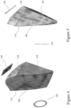
- FIGS. 1B , 4 and 5 respectively there are depicted a 2D optical layout and perspective and plan 3D CAD model views, respectively, of a freeform prism-lens absent any auxiliary optical elements as can be employed within the NR2I system according to an embodiment of the invention.
- a ray emitted from a point on the microdisplay is first refracted by the surface S3 130 next to the microdisplay. After two consecutive reflections by the surfaces S1' 115 and S2 120, the ray is transmitted through the surface S1 110 and reaches the exit pupil 150 of the system.
- the first surface (i.e., S1 110 and S1' 115) of the prism-lens is required to satisfy the condition of total internal reflection for rays reflected by this surface S1' 115.
- the rear surface S2 120 of the prism-lens may, optionally, be coated with a mirror coating for immersive NR2I systems thereby blocking the user's view of the real world scene except as presented upon the microdisplay.
- the surface S2 120 may be coated with a beam-splitting coating if optical see-through capability is desired using the auxiliary lens (not shown for clarity).
- the reference axes are set differently from the existing designs presented within the prior art.
- the Z-axis is along the viewing direction, but the Y-axis is parallel to the horizontal direction aligning with inter-pupillary direction, and the X-axis is in the vertical direction aligning with the head orientation.
- the reference coordinate system is rotated 90-degrees around the Z-axis.
- the overall prism-lens system is symmetric about the horizontal (YOZ) plane, rather than a typical left-right symmetry about the vertical plane.
- the optical surfaces (S1 110, S2 120, and S3 130) are decentered along the horizontal Y-axis and rotated about the vertical X-axis. As a result, the optical path is folded in the horizontal YOZ plane, corresponding to the direction of wider field of view, to form a prism-lens structure.
- This arrangement allows the microdisplay to be mounted on the temple side of the user's head, resulting in a much more balanced and ergonomic system packaging concept than a typical vertical-folding design with the microdisplay located above the eyebrow. It would be further evident that in the embodiments of the invention described within this specification that they differ from a typical vertical-folding design in which the FOV in the folding direction is narrower than the non-folding direction. Rather, embodiments of the invention have a FOV in the folding direction is much wider than the non-folding direction, which makes a high-performance design very challenging.
- the inventor's further targeted an NR2I system with a diagonal full FOV of about 40°, which corresponds therefore to a focal length of approximately 18 mm (0.7").
- This combination offers a reasonable balance between FOV and angular resolution (1.8 arc minutes per pixel).
- a large exit pupil is beneficial to account for the swiveling of the eyes in their sockets without causing vignetting or loss of image.
- a large pupil offers better tolerance also to the inter-pupillary distances (IPD) among different users without the need to mechanically adjust the eyepiece optics, and can allow moderate electronic IPD adjustment by laterally displacing the displayed pixels.
- IPD inter-pupillary distances
- the inventors set the exit pupil diameter to be 12 mm (0 . 5") with no more than 40% vignetting at the maximum field positions, which leads to a system with an F/# of about 1.5 for the center fields.
- a large eye clearance is also desirable to accommodate users wearing eyeglasses, but it affects the compactness of the viewing optics.
- a minimum 20mm (0.8") eye clearance was set to accommodate users wearing eyeglasses etc.
- the modulation transfer function was selected to evaluate the overall image sharpness and was set to be no less than 10% across the entire visual field at a spatial frequency of 50 lps / mm which corresponds to the Nyquist sampling frequency of the microdisplay selected for an embodiment of the invention.
- Table 1 Specifications of one embodiment of the NR2I System Element Parameter Specification Microdisplay Size 12.7mm (0.5") Active Display Area 10.14 ⁇ 7.60 mm (0.4" ⁇ 0.3" ) Resolution 1024 ⁇ 768 pixels Pixel Size 10 ⁇ m Freeform Prism-Lens Type Folded Effective Focal Length ⁇ 18 mm (0.7”) Exit Pupil Diameter 12 mm (0 .
- a suitable representation method should 1) provide adequate degrees of freedom; 2) require a reasonable amount of ray tracing time; 3) offer reliable convergence in the optimization process; and 4) be orthogonal. Many types of orthogonal or non-orthogonal polynomial equations can be utilized to describe a freeform surface.
- a freeform surface could be represented by Equations (1A) and (1B) where z is the sag along the local z -axis, x and y are the coordinates in the local coordinate system, k is the conic constant, c x is radius of curvature of surface in sagittal direction, c y is radius of curvature of surface in tangential direction, and C j is the coefficient for x 2m y n .
- a freeform surface shape symmetric to the X-axis is represented by an axially asymmetric quadratic and a set of orthogonal polynomials as given by Equation (2) where z is the sag along the local z-axis, x and y are the coordinates in the local coordinate system, c xx , c yy , and c xy are the curvature tensor at the origin, ⁇ is a conic-like constant, and r 0 is the radius of the surface.
- the optical performance of the designed system was assessed at representative field angles for these three design wavelengths.
- the distortion results depicted in Figure 6 imply that the system distortion is well controlled, being less than 5% at the edge of the field of view.
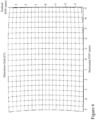
- Simulations and design adjustments included analysis of polychromatic MTF curves which were obtained for the 25-sampled fields depicted in Figure 7 and were evaluated for a centered pupil.
- the target spatial frequency of 50 cycles / mm corresponds to the threshold spatial frequency of the microdisplay with a 10 ⁇ m pixel size.
- the system achieved nearly 20% MTF value for the maximum field angle at the spatial frequency of 50 cycles / mm and an average MTF value of about 50% for the center 60% of the field of view.
- the average MTF is greater than 50% across the entire field of view at the frequency of 33 cycles / mm which would correspond to a microdisplay pixel of 15 ⁇ m.
- the optical resolution of the freeform prism-lens design according to an embodiment of the invention is much higher than the existing prism designs reported within the prior art.
- a further design constraint applied to the design of the freeform prism-lens 100 according to an embodiment of the invention by the inventors was that the freeform prism-lens 100 design should exploit a single type of optical material for lower complexity manufacturing.
- Materials may include, but not be limited to, for instance polymeric materials such as Poly Methyl MethAcrylate (PMMA) or a Cyclo Olefin Polymer (COP), although in other applications glasses and other optically transparent materials in the visible wavelength range may be employed.
- PMMA Poly Methyl MethAcrylate
- COP Cyclo Olefin Polymer
- this design constraint means that the full correction of chromatic aberrations due to optical dispersion is not feasible. This is often a limiting factor for designing a freeform prism-lens with high optical resolution for a broad optical spectrum such as the full human visual spectrum.
- the embodiment of the invention presented within Figure 1B was designed for use in conjunction with an organic light emitting display (OLED) which has a larger color gamut than some of the other common commercial microdisplay technologies. Accordingly, the optical performance needs to be balanced for a broad visible spectrum and as would be evident to one of skill in the art the freeform prism-lens design may be adjusted to the microdisplay or established for a broad visible spectrum allowing flexibility in microdisplay technology and emission characteristics.
- OLED organic light emitting display
- the image formed by each individual wavelength has achieved very high resolution, while the display position of any given image point can be separated from those of other wavelengths originating from the same pixel position on the microdisplay.
- the spatial displacements among different color elements may be digitally corrected by applying a pre-warping operation to each individual color channel such as described by the inventors in US Provisional Patent Application 62/150,911 entitled "Methods and Devices for Optical Aberration Correction".
- This full-field map provides data not only for image distortion correction, but also to correct spatial displacements among different color elements for electronic pre-compensation of chromatic aberration before display.
- FIG. 2 there is depicted a freeform prism-lens according to the embodiments of the invention depicted in respect of Figures 1A and 1B respectively and as described supra in respect of Figures 4 to 8 respectively.
- the surface adjacent to the exit pupil is labeled as S1 110 in the refraction path and as S1' 115 in the reflection path but is now depicted as being divided into three regions along these surfaces S1 110 and S1' 115 which are denoted as Region A 160, Region B 170, and Region C 180.
- Region A 160 all optical paths from the microdisplay, for example MicroDisplay 140 in Figures 1A and 1B respectively, to the exit pupil, for example Exit Pupil 150 in Figures 1A and 1B respectively, are reflected by surface S1 110 and hence are defined by reflection paths on surface S1' 115.
- Region C 180 all optical paths from the microdisplay to the exit pupil are transmitted by surface S1 110 and hence are defined by refraction paths on surface S1 110.
- the middle region, Region B 170, the optical paths from the microdisplay to the exit pupil are a combination of both those reflected by surface S1 110 and hence are defined by reflection paths on surface S1' 115 and those transmitted by surface S1 110 and hence are defined by refraction paths on surface S1 110.
- Region B 170 has a defined length.
- the Freeform Prism-Lens 100 may have no Region B 170 and Regions A 160 and Region C 180 may be either "continuously" adjacent or there may be a gap between regions of the surface S1 110 having internally reflected and transmissive paths.
- the Region A 160 of the Freeform Prism-Lens 100 may be reflective, e.g. silvered, painted, etc. to mask this area from light entry.
- the same may be applied to S2 120 and non-active regions of S3 130.
- stray light is prevented from entering the prism-lens through S2 and S3 by opaque mechanical assemblies, although other means such as silvering, partial silvering, painting etc. are evident alternatives.
- FIGS 9A to 9C respectively there are depicted side perspective, side elevation, and front elevation views of a bioptic immersive NR21 (BI-NR2I) system according to an embodiment of the invention exploiting freeform prism-lenses according to embodiments of the invention such as described and depicted supra in respect of Figures 1A to 8 .
- BI-NR2I bioptic immersive NR21
- the user has the BI-NR2I system pivoted down in front of their eyes.
- FIGs 10A to 10C respectively then there are depicted the same side perspective, side elevation, and front elevation views of the BI-NR2I system wherein the user has raised the BI-NR2I system up and views the external environment directly.
- the BI-NR2I system is attached to a frame that sits onto the bridge of the user's nose and the upper surfaces of their ears in a similar manner to conventional eyeglasses. However, the BI-NR21 system as depicted can be pivoted into and out of the line of sight of the user.
- the NR21 system may be rigidly attached such that it can only be viewed immersive (I-NR21) when worn or the NR21 system may be transmissive (T-NR2I) or bioptic transmissive (BT-NR21) allowing the user to view the external world whilst viewing the NR2I system concurrently.
- the NR21 system may be demountable from the frame such as described by the inventors within World Patent Application PCT/CA2016/000,189 filed July 6, 2016 entitled “Methods and Devices for Demountable Head Mounted Displays.”
- the NR2I system may also support additional positions either discretely or in a continuous manner such as described and depicted in U.S. Patents 8,976,086 and 9,372,348 entitled “Apparatus and Method for a Bioptic Real Time Video System.”
- the NR2I system incorporates a pair of frames and a NR2I display which is controlled by a microprocessor.
- the microprocessor may be a general purpose microcontroller, microprocessor, or computer o some embodiments of the invention but in other embodiments of the invention it may be an application specific integrated circuit (ASIC) or field programmable gate array (FPGA).
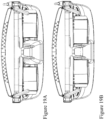
- the frame as depicted in Figures 14A may be a lensless frame solely intended to support the NR2I display and form part of the NR21 system or alternatively it may be a frame with a single prescription lens or a pair of prescription lenses as depicted in Figure 14B .
- the lens within the frames depicted in Figures 14B and 14C may be polarizing sheets such as employed in sunglasses, photochromic glass as employed in sunglasses, and filter(s) either in combination with prescription elements or in isolation.
- a neutral density filter or photochromic glass may be disposed to the side distal from the user to reduce ambient lighting either by a fixed amount or variable amount.
- the NR21 displays / systems have dual optical trains, one for each eye.
- the NR2I displays / systems may be designed / configured for a single eye, e.g. the user's left or right, or may be configured in split design allowing the use of either one of or both of left and right elements.
- Headband 1110 such as depicted in Figure 11A and as described within World Patent Application PCT/ CA2016/000,189 filed July 6, 2016 entitled “Methods and Devices for Demountable Head Mounted Displays.”
- This provides additional support such that the NR2I display load is not all directly borne by the user's nose and ears.
- the headband 1110 is attached using Attachment Clips 1210 which are depicted in Figure 12A but omitted for clarity in Figure 11A .
- An additional strap may be attached around the rear of the user's head, not depicted for clarity, which attaches to the rear portions of the Attachment Clips 1210.
- the NR21 display may include one or more image capture devices such as a CCD camera.
- the NR2I display would include a Camera 1120 facing forward although in other embodiments of the invention two or more cameras may be integrated with different viewpoints relative to the user's line of sight, e.g. lateral, rear, etc.
- a visible camera and an infrared (IR) camera may be integrated allowing the user in some applications to view thermal imagery as well as their normal sight.
- the microdisplays within the NR2I may display information acquired from the camera(s) and / or one or more other sources of content including, but not limited to, other cameras, video cameras, web content, documents, streaming video, etc.
- the NR2I display may include one or more eye and / or pupil tracking sensors with their associated electronics either forming part of the NRI display electronics by design or by addition.
- a configuration is depicted in Figure 3 wherein the Freeform Prism-Lens 100 is depicted with a Freeform Corrector 160 and the MicroDisplay 140.
- NIR Near Infra-Red
- LED 210 providing infra-red illumination of the user's eye
- NIR Sensor 220 which provides NIR detection and spatial signal(s) such that the user's eye is tracked allowing this information to be used either in respect of modifying the image presented to the user, augmentation content provided to the user, etc. It would be evident that if spatial separation of the NIR optical signals from the visible signals from the MicroDisplay 140 can be achieved that placement of the NIR LED 210 and NIR Sensor 220 may be varied from that depicted of either side the MicroDisplay 140.
- a light source / flashlight 1130 disposed within the NR2I display as depicted in Figure 11B is a light source / flashlight 1130 to provide illumination for the user.
- two or more light sources / flashlights may be provided.
- the NR2I system may include a range finder. As depicted in Figure 11B such a range finder, second camera etc. may be fitted as depicted with first and second optical elements 1140 and 1150 respectively within the central portion of the NR2I display depicted in Figure 11B .
- the NR21 display may communicate to another electronic device, e.g. a PED and / or FED, exploiting a wired and / or wireless link.
- a wired link being depicted in Figure 11B via cable 1160 which may exploit industry standard or custom connector interfaces and / or communications standards.
- a common NR21 display Core 1160 may be configured with a wired interface via Cable 1170 as depicted in Figure 11D and / or configured via wireless interfaces via first and second Antennae 1180 and 1190 respectively.
- First and second Antennae 1180 and 1190 may relate to a common wireless interface or they may relate to different wireless interfaces according to the design of the NR21 display and its interfaces to external network / devices etc.
- the NR2I display may support IEEE 802.11 Wi-Fi for accessing local routers, FEDs, digital set-top boxes etc. and Bluetooth to support communications to the user's PED.
- NR2I displays may support a single or multiple display technologies according to the design of the NR21 display and the resulting specifications placed on the microdisplay and therein the design and implementation of the freeform prism-lens such as described supra in respect of Section 1.
- the microdisplay(s) may be liquid crystal, e.g. Liquid Crystal on Silicon (LCOS), Light Emitting Diode (LED) based, or Organic Light Emitting Diode (OLED) technology.
- the freeform prism-lens may be reflective by design and / or exploit a reflective coating.
- the freeform prism-lens may be anti-reflection coated prior to assembly with additional optics such as the Freeform Corrector 160 in Figure 1A .
- the visual image presented to the user may be the same, different, external view acquired with camera, or external content acquired from a PED / FED and / or remote source.
- the image from the Camera 1120 may be presented to both eyes whilst the user's left eye is presented with the digital content overlaid to the image and the user's right eye is not or vice-versa.
- one eye of the user is presented with the image with or without digital content overlay whilst the other eye is presented with a modified image, such as with highlighted edges, for example.
- the user is presented with left and right images with or without digital content overlay, image modification etc. If, for example, the user is employing a NR21 device with visible and infrared cameras or receiving dual camera feeds from visible and infrared cameras then these may be presented to the user in different eyes, for example.
- the Camera 1120 may be a charge coupled device (CCD) camera with high depth-of-field optics such as found in a range of high volume consumer electronic devices such as smartphones, a high quality CCD sensor such as employed in digital SLRs allowing high resolution magnification and / or image stabilisation etc.
- the Camera 1120 may be a Complementary Metal Oxide Semiconductor (CMOS) image sensor with appropriate optics.
- CMOS Complementary Metal Oxide Semiconductor
- the Camera 1120 may be external to the NR2I display and associated with an item of apparel of the user or an item of equipment employed by the user or independent of the user, their clothing and equipment.
- the image capture device is any imaging device with an analog or digital signal output that can be sent to the NR2I display for processing or to the user's PED for processing and display on the NR21 display.
- the optional eye tracking sensor is also in communication with the NR21 processing electronics and determines where in the visual field of view (FoV) the individual is looking. In one embodiment, this sensor operates by following the position of the user's pupil.
- Such eye tracking devices are common in prior art "heads-up-displays" (HUDs) utilized by military pilots.
- An embodiment of pupil-tracking using a horizontally-oriented wedge-shaped freeform prism-lens is shown in Figure 3 .
- the display is augmented with NIR LED 210 and NIR Sensor 220 with their light paths passing through freeform surface S3, and located proximal to the MicroDisplay 140.
- IR light is emitted, bounced off the user's eye, and returns to the IR sensor, whereupon the received image of the eye is digitized, and the pupil's motion tracked using digital motion-tracking algorithms.
- the eye tracking sensor uses a combination of mirrors and prisms such that the optical path for the eye tracking sensor is orthogonal to the pupil. Eye tracking is used to determine the region of interest (ROI) within the FoV and either adjust and / or augment the content being presented to the user.
- ROI region of interest
- the eye tracking can ensure, for example, that damaged areas of the user's retina are avoided for displaying salient content within the image, the modified image, overlay content etc. or a combination thereof.
- the eye-tracking information would typically be averaged, filtered, etc. through software to minimize the sensitivity to random eye movements, blinks, etc., and to optimize the system for various usage models. For example, reading English requires specific eye tracking performance in the left to right direction that is different from that in the right to left direction, and different again from that in the vertical direction.
- FIGS 12A and 12B there are depicted the bioptic immersive NR21 system of Figures 9A to 10C in isolation from a user in side elevation for NR2I down and raised configurations respectively.
- Figures 13A and 13B depict the bioptic immersive NR21 system of Figures 9A to 10C in isolation from a user in bottom and top elevations with the NR21 down.
- the NR2I display is depicted assembled together with a lensless frame such as depicted by first frame 1400A in Figure 14A with Nose Bridge 1410 and Arms 1420 which rest upon the ears of the user.
- Second frame 1400B comprises Lenses 1430, e.g. tinted, polarizing or photochromic, together with Upper Baffles 1440 and Side Baffles 1450 which block extraneous light.
- Third frame 1400C comprises Prescription Lenses 1460. It would be evident that the Lenses 1430 may also be prescription lenses and / or that Prescription Lenses 1460 may be tinted and / or coated. Equally, Upper Baffles 1440 and Side Baffles 1450 may be applied to either first frame 1400A or third frame 1400C.
- FIGs 15A to 15E a NR2I display such as employed within the NR2I systems depicted in Figures 9A to 13B sequentially separated to a subset of its constituent parts.
- the user worn NR21 display is depicted in Figure 15A and is then depicted in Figure 15B with the Top Cover / Heat Spreader 1510 removed which is depicted in Figure 15E .
- the remainder of the upper cover fitting over the region where the electrical feedthrough for the wired interconnection fits.
- the Top Cover / Heat Spreader 1510 allows for heat generated by the electronics associated with the microdisplays, wired interface, wireless interface and image processing etc. are dissipated.
- Top Cover / Heat Spreader 1510 is formed from a thermally conductive material and formed with surface features to increase the overall surface area in contact with air compared to the surface area of the Top Cover / Heat Spreader 1510 itself.
- Top Cover / Heat Spreader 1510 material may be selected from the group comprising metals such as copper, aluminum, zinc, and nickel for example, thermally conductive plastics such a carbon fiber loaded epoxies, alloys such as cemented carbide ( WC -Co ), copper tungsten ( WCu ), copper brass ( Cu 0.7 Ni 0.3 ), and thermally conductive ceramics such as aluminum nitride ( AlN ) or silicon carbide ( SiC ).
- Figure 15C depicts the NR2I Core 1160 and first and second Antennae 1180 and 1190 with the NR2I Case 1520 depicted in Figure 15D removed.
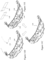
- This assembly is then depicted in Figure 16A wherein removal of the Core 1160 and first and second Antennae 1180 and 1190 yields right hand side (RHS) Prism-Lens Optical Display (POD) depicted in Figure 16B and left hand side (LHS) POD depicted in Figure 16C .
- RHS right hand side
- LHS left hand side
- fixturing includes the provision for independent lateral translation of the two PODs, for instance using rail-shaped Mounting 1640, in order to allow lateral motion to accommodate users of differing inter-pupil distance (IPD).
- Each POD may therefore be laterally moved by sliding the POD Mounting 1640 along a corresponding mounting projection within the Core 1160 and fixing the POD(s) in position when the correct Inter-Pupil Distance (IPD) is achieved.
- MicroDisplay 1620 mounted to the Casing 1610 and Free Form Prism-Lens 1630 disposed within the Casing 1610.
- the Casing 1610 also includes electrical connections for power and data to the MicroDisplay 1620 from the electronics within the NR2I display.
- an identical free-form prism-lens may be used in both left and right POD assemblies.
- the free-form prism-lenses within the left and right POD assemblies are not identical but are in fact symmetrical mirror-images of each other.
- the left and right free-form prism-lenses may be symmetrical mirror-images that are then modified to address specific issues relating to differences between the user's left and right eyes.
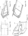
- FIG. 16D Casing 1610 as depicted in Figure 16D is repeated as Figure 17A .
- Figure 17B depicts the front face of the Casing 1610 as a discrete element from the viewing perspective of the user.
- Window 1710 represents the image region within which the MicroDisplay 1620 is projected to the user's pupil via the Free-Form Prism-Lens 1630.
- the portion of surface S1 that is not used for display is covered by the opaque baffle 1720 in order to minimize stray light from entering surface S1, then internally reflecting and corrupting the user's perception of the image.
- This baffling alternately might be applied directly to surface S1 of Prism-Lens 1630 as an opaque, absorbent, silvered, or other coating.
- FIGS 17C and 17D depict cross-sections of the Casing 1610 wherein the external geometry of the Free-Form Prism Lens 1630 is evident. Arrow A depicts the region wherein the MicroDisplay 1620 is positioned. Further, referring to Figure 18A the Casing 1610 is depicted representing an immersive shell for assembly of the MicroDisplay 1620 and Free-Form Prism Lens 1630 where the Casing 1610 has material disposed proximate the surface S2 of the Free-Form Prism Lens 1630.
- FIGS 19A and 19B respectively an NR2I display is presented from the user's perspective allowing the POD adjustment for display Inter-Pupil Distance (IPD) to be visualized, nominally defined as the lateral distance between the centres of the left and right viewing areas, and nominally set to match the distance between the user's pupils, although the user might choose alternate preferred locations, for instance locating the displays closer than their own IPD for consistent close-up use.
- IPD Inter-Pupil Distance
- the PODs are depicted at their maximum IPD of approximately 70mm (approximately 2.75 inches) where the mechanical IPD adjustment is made by sliding the PODs in and out upon their rail-shaped mounts, though any POD attachment scheme that allows lateral translation might be employed.
- the PODs are depicted at their minimum IPD of approximately 40mm (approximately 1.6 inches).
- an initial or average IPD setting for the user is fixed, for example using a set-screw operating on the POD assemblies.
- the NR2I display electronics may further dynamically control the horizontal location of the images displayed to the user's eyes (and thus the effective display IPD) through simple digital translation of the images displayed on each of the two microdisplays. For example, to digitally increase the IPD after the PODs have been mechanically fixed the image displayed by the left POD would be digitally shifted left, and the image displayed by the right POD digitally shifted right.
- Iteration between digital and mechanical IPD adjustment may be employed to reduce fitting time, for example by starting from an initial factory default IPD, digitally adjusting until the user is satisfied with the setting, reading the digital IPD setting from the NR21 system, then mechanically adjusting the IPD to the digital setting as read, in order to maximize usable display area.
- the combination allows pixel-level IPD control. Additional micro-display pixels beyond the desired display resolution may be employed, e.g. "border" pixels which are similarly used to translate images for digital image-stabilization, or if no such information or pixels are available, suitable null data may be presented.
- the user is cross-eyed staring at the bridge of their nose, and the IPD has reduced substantially as the eyes gaze turned inwards.
- Typical NR21 systems provide the image at a fixed focal depth of infinity, and the IPD of the images are fixed, which may result in diplopia (double-vision) or eyestrain when viewing close objects, as the eyes are not operating in a "natural" manner for close objects. Improved usability can be achieved if the electronic IPD adjustment is made dynamic, and according to the distance of the object being viewed.
- the auto-focus features of the image capture system may be used to direct the digital image processing system to laterally translate the images inwards towards the nose as the focus decreases from infinity. This dynamic IPD display can more accurately mimic real-world conditions and behaviours, reducing eyestrain and improving usability.
- the function that relates distance to the object to the number of pixels by which to digitally offset the image may be simple or complex.
- a simple example might be to take distance information from the rangefinder 2220, and for distances L D 2270 less than some threshold T to laterally translate the left and right image pixels towards each other by a function of L D 2270 and T , f ( T,D ), until a second, minimum, distance threshold is reached.
- a more complex example might consider the geometry of the situation as follows in order to take advantage of the small angle approximation sin( x ) ⁇ x , and cos( x ) ⁇ 1 for small x .
- the width of the display areas 2250 are covered by a micro-display of P pixels in width, achieving a horizontal field-of-view angle of V degrees.
- the small-angle approximation here is that there are P / V pixels per degree of viewing angle.
- Equation (5) the number of pixels to shift may be given by Equations (6) or (7) for example where f (*) might be the identity function or alternatively may be one of a number of functions that threshold, limit, scale, etc.
- image translations may be employed alone or in combination in order to minimize a visual degradation of the user, such as double-vision for example.
- An assistant or the user themselves may employ an input device or devices to select and adjust the translations, rotations, corrections etc. applied to improve the user's visual acuity for that particular user.
- These settings may be modified over time through a training program to train one or more aspects of the user's visual system, including, for example, their eye, muscles, nerves, neural processing, towards a specific objective (e.g. "lazy eye” muscle strengthening.
- it may be beneficial to occlude an image continuously, periodically, randomly, presented to one or other eye, or on only portions of a presented image to allow a weaker eye and/or further neural processing to strengthen itself in a training process.
- such training may be invoked when the user is playing a game or performing another predetermined task or it may be continuously applied.
- the portion of an image to one or other eye may be varied over time based upon one or more factors including, for example, current activity, degree of image processing applied, and image source.
- the code snippet of Figure 21B has been augmented relative to that of Figure 21A by the inclusion of a lateral image-shift using the variable uXShift which can be independently programmed for left and right displays such that the effective display IPD can be varied a function of viewed-object distance, thus achieving a degree of bio-mimicry of the natural viewing environment.
- the integrated camera range-finding mechanism depicted for example as first and second optical elements 1140 and 1150 respectively in Figure 11 , via associated electronics and processing may be employed to provide distance information to the image-processing subsystem.
- the induced lateral shift may be a simple function, e.g.
- uXShift x / d
- x is a configurable scaling parameter
- d is the distance established by the NR21 display / system such as via the rangefinder.
- x is a configurable scaling parameter
- d is the distance established by the NR21 display / system such as via the rangefinder.
- alternate means of range-finding, alternate functions for mapping from range to uXShift , etc. are within the scope of the invention.
- an image processing pipeline may be employed to apply the vertical translations and/or offsets, rotational translations and/or offsets, and other mappings / corrections required by the user.
- the NR2I may be adjusted to reflect a particular vision issue for a user in respect of this where the natural retinal motion may be different for the user in one or both eyes.
- the process first checks that the lateral shift is still within the valid image area, and if not, replaces the image data with (0,0,0,1) i.e. an opaque black display.
- An improvement upon this black-filling approach within scope of the current invention is to provide image-sources of greater pixel-width than that of the display so that full display-width is maintained as the users eyes rotate and the display-images are shifted or panned across the source image.
- a portable electronic device 2004 supporting an interface to a NR2I 2070 according to an embodiment of the invention.
- the protocol architecture is also depicted within the PED 2004 that includes a portable electronic device (PED) 2004, such as a smartphone, an Access Point (AP) 2006, such as a Wi-Fi access point or wireless cellular base station, and one or more network devices 2007, such as communication servers, streaming media servers, and routers for example.
- Network devices 2007 may be coupled to AP 2006 via any combination of networks, wired, wireless and/or optical communication.
- the PED 2004 includes one or more processors 2010 and a memory 2012 coupled to processor(s) 2010.
- AP 2006 also includes one or more processors 2011 and a memory 2013 coupled to processor(s) 2011.
- processors 2010 and 2011 includes a central processing unit (CPU), a digital signal processor (DSP), a reduced instruction set computer (RISC), a complex instruction set computer (CISC) and the like.
- processors 2010 and 2011 may be part of application specific integrated circuits (ASICs) or may be a part of application specific standard products (ASSPs).
- a non-exhaustive list of examples for memories 2012 and 2013 includes any combination of the following semiconductor devices such as registers, latches, ROM, EEPROM, flash memory devices, non-volatile random access memory devices (NVRAM), SDRAM, DRAM, double data rate (DDR) memory devices, SRAM, universal serial bus (USB) removable memory, and the like.
- semiconductor devices such as registers, latches, ROM, EEPROM, flash memory devices, non-volatile random access memory devices (NVRAM), SDRAM, DRAM, double data rate (DDR) memory devices, SRAM, universal serial bus (USB) removable memory, and the like.
- PED 2004 may include an audio input element 2014, for example a microphone, and an audio output element 2016, for example, a speaker, coupled to any of processors 2010.
- PED 2004 may include a video input element 2018, for example, a video camera, and a visual output element 2020, for example an LCD display, coupled to any of processors 2010.
- the visual output element 2020 is also coupled to display interface 2020B and display status 2020C.
- PED 2004 includes one or more applications 2022 that are typically stored in memory 2012 and are executable by any combination of processors 2010.
- PED 2004 includes a protocol stack 2024 and AP 2006 includes a communication stack 2025.
- protocol stack 2024 is shown as IEEE 802.11/15 protocol stack but alternatively may exploit other protocol stacks such as an Internet Engineering Task Force (IETF) multimedia protocol stack for example.
- IETF Internet Engineering Task Force
- Protocol stack 2024 exploits a protocol stack but is not expanded for clarity. Elements of protocol stack 2024 and AP stack 2025 may be implemented in any combination of software, firmware and/or hardware.
- Protocol stack 2024 includes an IEEE 802.11/15-compatible PHY module 2026 that is coupled to one or more Front-End Tx/Rx & Antenna 2028, an IEEE 802.11/15-compatible MAC module 2030 coupled to an IEEE 802.2-compatible LLC module 2032.
- Protocol stack 2024 includes a network layer IP module 2034, a transport layer User Datagram Protocol (UDP) module 2036 and a transport layer Transmission Control Protocol (TCP) module 2038. Also shown is WPAN Tx/Rx & Antenna 2060, for example supporting IEEE 802.15.
- UDP User Datagram Protocol
- TCP Transmission Control Protocol
- Protocol stack 2024 also includes a session layer Real Time Transport Protocol (RTP) module 2040, a Session Announcement Protocol (SAP) module 2042, a Session Initiation Protocol (SIP) module 2044 and a Real Time Streaming Protocol (RTSP) module 2046.
- Protocol stack 2024 includes a presentation layer media negotiation module 2048, a call control module 2050, one or more audio codecs 2052 and one or more video codecs 2054.
- Applications 2022 may be able to create maintain and/or terminate communication sessions with any of devices 2007 by way of AP 2006. Typically, applications 2022 may activate any of the SAP, SIP, RTSP, media negotiation and call control modules for that purpose.
- information may propagate from the SAP, SIP, RTSP, media negotiation and call control modules to PHY module 2026 through TCP module 2038, IP module 2034, LLC module 2032 and MAC module 2030.
- elements of the PED 2004 may also be implemented within the AP 2006 including but not limited to one or more elements of the protocol stack 2024, including for example an IEEE 802.11-compatible PHY module, an IEEE 802.11-compatible MAC module, and an IEEE 802.2-compatible LLC module 2032.
- the AP 2006 may additionally include a network layer IP module, a transport layer User Datagram Protocol (UDP) module and a transport layer Transmission Control Protocol (TCP) module as well as a session layer Real Time Transport Protocol (RTP) module, a Session Announcement Protocol (SAP) module, a Session Initiation Protocol (SIP) module and a Real Time Streaming Protocol (RTSP) module, media negotiation module, and a call control module.
- UDP User Datagram Protocol
- TCP Transmission Control Protocol
- RTP Real Time Transport Protocol
- SAP Session Announcement Protocol
- SIP Session Initiation Protocol
- RTSP Real Time Streaming Protocol
- NR21 2070 which is coupled to the PED 2004 through WPAN interface between Antenna 2071 and WPAN Tx/Rx & Antenna 2060.
- Antenna 2071 is connected to NR2I Stack 2072 and therein to processor 2073.
- Processor 2073 is coupled to camera 2076, memory 2075, and display 2074.
- NR2I 2070 being for example NR21 370 described above in respect of Figure 3 .
- NR21 2070 may, for example, utilize the processor 2010 within PED 2004 for processing functionality such that a lower power processor 2073 is deployed within NR2I 2070 controlling acquisition of image data from camera 2076 and presentation of modified image data to user via display 2074 with instruction sets and some algorithms for example stored within the memory 2075. It would be evident that data relating to the particular individual's visual defects may be stored within memory 2012 of PED 2004 and / or memory 2075 of NR2I 2070. This information may be remotely transferred to the PED 2004 and/ or NR2I 2070 from a remote system such as an optometry system characterising the individual's visual defects via Network Device 2007 and AP 2006.
- a remote system such as an optometry system characterising the individual's visual defects via Network Device 2007 and AP 2006.
- the eSight Generation 3 NR2I supports a wired USB connection to the PED / FED as well as a Bluetooth connection. Accordingly, a Wi-Fi connection to the NR21 2070 would be via the PED / FED and either the Bluetooth or wired connection.
- the processing of image data may be solely within the NR2I 2070, solely within the PED 2004, distributed between them, capable of executed independently upon both, or dynamically allocated according to constraints such as processor loading, battery status etc. Accordingly, the image acquired from a camera associated with the NR21 2070 may be processed by the NR21 2070 directly but image data to be displayed acquired from an external source processed by the PED 2004 for combination with that provided by the NR2I 2070 or in replacement thereof.
- processing within the NR2I 2070 may be offloaded to the PED 2004 during instances of low battery of the NR2I 2070, for example, wherein the user may also be advised to make an electrical connection between the NR2I 2070 and PED 20040 in order to remove power drain from the Bluetooth interface or another local PAN etc.
- the NR2I with associated PED may accordingly download original software and / or revisions for a variety of functions including diagnostics, display image generation, and image processing algorithms as well as revised ophthalmic data relating to the individual's eye or eyes. Accordingly, it is possible to conceive of a single generic NR2I being manufactured that is then configured to the individual through software and patient ophthalmic data.
- the elements of the PED required for network interfacing via a wireless network (where implemented), NR21 interfacing through a WPAN protocol, processor, etc. may be implemented in a discrete standalone PED as opposed to exploiting a consumer PED.
- a PED such as described in respect of Figure 20 allows the user to adapt the algorithms employed through selection from internal memory as well as define an ROI through a touchscreen, touchpad, or keypad interface for example.
- the user interface on the PED may be context aware such that the user is provided with different interfaces, software options, and configurations for example based upon factors including but not limited to cellular tower accessed, Wi-Fi / WiMAX transceiver connection, GPS location, and local associated devices.
- the NR2I may be reconfigured upon the determined context of the user based upon the PED determined context.
- the NR2I may determine the context itself based upon any of the preceding techniques where such features are part of the NR2I configuration as well as based upon processing the received image from the camera.
- the NR2I configuration for the user wherein the context is sitting watching television based upon processing the image from the camera may be different to that determined when the user is reading, walking, driving etc.
- the determined context may be overridden by the user such as, for example, the NR2I associates with the Bluetooth interface of the user's vehicle but in this instance the user is a passenger rather than the driver.
- a third party vendor may offer an algorithm not offered by the NR2I vendor or the NR2I vendor may approve third party vendors to develop algorithms addressing particular requirements.
- a third party vendor may develop an information sign set for the Japan, China etc. whereas another third party vendor may provide this for Europe.
- the configuration of the NR2I may be common to multiple electronic devices and their "normal” world engagement or the configuration of the NR2I for their "normal” world engagement and the electronic devices may be different. These differences may for example be different processing variable values for a common algorithm or it may be different algorithms.
Landscapes
- Engineering & Computer Science (AREA)
- Physics & Mathematics (AREA)
- Computer Hardware Design (AREA)
- General Physics & Mathematics (AREA)
- Theoretical Computer Science (AREA)
- Human Computer Interaction (AREA)
- General Engineering & Computer Science (AREA)
- Optics & Photonics (AREA)
Claims (14)
- Ein Near-to-Eye (NR21) - Anzeigesystem, das Folgendes umfasst:eine erste Anordnung, die Folgendes umfasst:
eine erste Freiform-Prismenlinse, die Folgendes umfasst:a: eine erste Freiform-Oberfläche (S3 130), die konfiguriert ist, um Licht von einem ersten Mikrodisplay (140) zu empfangen und das empfangene Licht in den Körper der ersten Freiform-Prismenlinse (100) zu übertragen;b: eine zweite Freiform-Oberfläche (S1 110), die konfiguriert ist, um das von der ersten Freiform-Oberfläche (S3 130) in den Körper der ersten Freiform-Prismenlinse (100) übertragene Licht zu empfangen, und konfiguriert ist, um das empfangene Licht über einen vorbestimmten Abschnitt der zweiten Freiform-Oberfläche (51 110) zu reflektieren; undc: eine dritte Freiform-Oberfläche (S2 120), die konfiguriert ist, um das von der zweiten Freiform-Oberfläche (S1 110) reflektierte Licht zu empfangen und das Licht zumindest teilweise zurück zur zweiten Freiform-Oberfläche (51 110) hin und dann aus der ersten Freiform-Prismenlinse (100) zu reflektieren, unddas erste Mikrodisplay (140) zum Projizieren von Bildlicht auf einen vorbestimmten Bereich der ersten Freiform-Oberfläche (S3 130) der genannten ersten Freiform-Prismenlinse (100) projiziert wird, wobeidas erste Mikrodisplay (140) fest in Position gehalten wird durch die genannte Anordnung relativ zur genannten ersten Freiform-Oberfläche (S3 130) der ersten Freiform-Prismenlinse (100) und in der Nähe einer Schläfe des Benutzers, so nah wie möglich (nearest) am Auge des Benutzers, das das projizierte Bildlicht betrachtet, wobei eine solche Anordnung derartige Befestigungsmerkmale aufweist,dass eine seitliche Bewegung der Anordnung über das horizontale Sichtfeld des Benutzers ermöglicht wird, wenn sie an einem Körper des NR21-Systems befestigt ist,die Reflexionen an jeder der zweiten Freiform-Oberfläche und die zumindest teilweise Reflexion an der dritten Freiform-Oberfläche innerhalb einer ausgewählten Faltungsebene auftreten, und wobei die erste Freiform-Prismenlinse (100) ein Sichtfeld in der Faltungsebene aufweist, das größer ist als das Sichtfeld in einer Ebene senkrecht zur Faltenebene;das NR21-Anzeigesystem ferner Folgendes umfasst:eine zweite Anordnung, umfassend:
eine zweite Freiform-Prismenlinse, umfassend:a: eine weitere erste Freiform-Oberfläche (S3 130), die konfiguriert ist, um Licht von einem zweiten Mikrodisplay (140) zu empfangen und das empfangene Licht in den Körper der zweiten Freiform-Prismenlinse (100) zu übertragen;b: eine weitere zweite Freiform-Oberfläche (S1 110), die konfiguriert ist, um das von der weiteren ersten Freiform-Oberfläche (S3 130) in den Körper der zweiten Freiform-Prismenlinse (100) übertragene Licht zu empfangen, und konfiguriert ist, um das empfangene Licht über einen vorbestimmten Abschnitt der anderen zweiten Freiform-Oberfläche (51 110) zu reflektieren; undc: eine weitere dritte Freiform-Oberfläche (S2 120), die konfiguriert ist, um das von der weiteren zweiten Freiform-Oberfläche (S1 110) reflektierte Licht zu empfangen, und um das Licht zumindest teilweise zurück zur weiteren zweiten Freiform-Oberfläche (51 110) und dann aus der zweiten Freiform-Prismenlinse (100) heraus zu reflektieren, unddas zweite Mikrodisplay (140) zum Projizieren von Bildlicht auf einen vorbestimmten Bereich der genannten weiteren ersten Freiform-Oberfläche (S3 130) der genannten zweiten Freiform-Prismenlinse (100), wobeidas zweite Mikrodisplay (140) fest in Position gehalten wird relativ zur genannten weiteren ersten Freiform-Oberfläche (S3 130) der zweiten Freiform-Prismenlinse und in der Nähe der anderen Schläfe des Benutzers durch die genannte zweite Anordnung, wobei eine solche Anordnung derartige Befestigungsmerkmale aufweist, dass eine seitliche Bewegung der zweiten Anordnung über das horizontale Sichtfeld des Benutzers ermöglicht wird, wenn sie am Körper des NR21-Systems angebracht ist, wodurch die Positionen und der Abstand der ersten Anordnung und der zweiten Anordnung in Abhängigkeit von den Positionen und dem Pupillenabstand der Augen des Benutzers festgelegt werden können. - Das NR21-Anzeigesystem nach Anspruch 1, wobeidie erste Freiform-Oberfläche (S3 130) der ersten Freiform-Prismenlinse (100) durch eine Fläche definiert ist, die mindestens eines von nicht-rotationssymmetrisch ist und nicht-symmetrische Merkmale aufweist und konfiguriert ist, um das empfangene Licht vom ersten Mikrodisplay (140) in den Körper der ersten Freiform-Prismenlinse Linse (100) und in Richtung einer zweiten Freiform-Oberfläche (S1 110) der genannten ersten Freiform-Prismenlinse (100) zu übertragen, wobeidie zweite Freiform-Oberfläche (S1 110) der ersten Freiform-Prismenlinse (100) durch eine Fläche definiert ist, die mindestens eines von nicht-rotationssymmetrisch ist und nicht-symmetrische Merkmale aufweist und konfiguriert ist, um über einen ersten Abschnitt der zweiten Freiform-Oberfläche (S1 110) Licht vom ersten Mikrodisplay (140), das durch die erste Freiform-Oberfläche (S3 130) in die erste Freiform-Prismenlinse (100) eintritt, in Richtung einer dritten Freiform-Oberfläche (S2 120) der ersten Freiform-Prismenlinse (100) intern zu reflektieren, und konfiguriert ist, um über einen zweiten Abschnitt der zweiten Oberfläche Licht, das von der zweiten Freiform-Oberfläche (S1 110) reflektiert wird, in Richtung der Augen des Benutzers zu übertragen; und wobeidie dritte Freiform-Oberfläche (S2 120) der ersten Freiform-Prismenlinse (100) konfiguriert ist, um das vom ersten Abschnitt der zweiten Freiform-Oberfläche (S1 110) reflektierte Licht zu empfangen und das Licht intern zurück zum zweiten Abschnitt der zweiten Freiform-Oberfläche (S1 110) zu reflektieren.
- Das NR21-Anzeigesystem nach Anspruch 2, wobei
mindestens eines von:der erste und der zweite vorbestimmte Bereich der zweiten Freiform-Oberfläche (S1 110) überlappen; unddie erste Freiform-Prismenlinse (100) eine effektive f-Zahl (F/#) des Mittelfelds von weniger als 3,5 und einen Austrittspupillendurchmesser von mindestens 8 mm aufweist. - Das NR21-Anzeigesystem nach Anspruch 1, wobei
mindestens eine der Freiform-Oberflächen der ersten Freiform-Prismenlinse (100) durch ein axial asymmetrisches Quadrat und einen Satz orthogonaler Polynome beschrieben wird:


- Das NR21-Anzeigesystem nach Anspruch 4, wobei
mindestens eines von:ein Teilabschnitt des ersten Abschnitts der zweiten Freiform-Oberfläche (S1 110) der ersten Freiform-Prismenlinse (100), der den zweiten Abschnitt der zweiten Freiform-Oberfläche (S1 110) der ersten Freiform-Prismenlinse (100) nicht überlappt, ist zumindest eines der Folgenden: mit einem reflektierenden Material beschichtet, mit einem Material beschichtet, das externes Licht blockiert, das in die erste Freiform-Prismenlinse eintritt, und durch einen undurchsichtigen Abschnitt einer Anordnung abgedeckt, die die erste Freiform-Prismenlinse (100) enthält, um zu verhindern, dass externes Licht durch den genannten nicht überlappenden Abschnitt in die erste Freiform-Prismenlinse (100) eindringt;die dritte Freiform-Oberfläche (S2 120) der ersten Freiform-Prismenlinse (100) ist verspiegelt, um ihre Reflektivität zu erhöhen; undeine Hilfslinse ist in der Nähe der dritten Freiform-Oberfläche (S2 120) der ersten Freiform-Prismenlinse (100) angeordnet, wobei die Hilfslinse konfiguriert ist, um mindestens eines von optischer Verzerrung und optischer Bildverschiebung einer realen Szene, die vom Benutzer durch die erste Freiform-Prismenlinse (100) und die Hilfslinse betrachtet wird, zu minimieren. - Das NR21-Anzeigesystem nach Anspruch 5, wobei,
wenn das NR2I-Anzeigesystem die Hilfslinse beinhaltet, die Hilfslinse eine Oberfläche zum Auge des Benutzers hin aufweist, die dieselbe Oberflächengeometrie wie die dritte Freiform-Oberfläche (S2 120) der ersten Freiform-Prismenlinse (100) aufweist und in optischem Kontakt mit der dritten Freiform-Oberfläche (S2 120) der ersten Freiform-Prismenlinse (100) angeordnet ist. - Das NR2I-Anzeigesystem nach Anspruch 1, wobei
mindestens eines von:der Augenabstand beträgt mindestens 18 mm, unddas Sichtfeld ist mindestens eines von: größer oder gleich 28 Grad in der Horizontalen und größer oder gleich 21 Grad in der Vertikalen. - Das NR2I-Anzeigesystem nach Anspruch 1, wobei
mindestens eines von:die räumliche Verzerrung bei maximalem Feldwinkel beträgt weniger als 10 %;die effektive Brennweite beträgt weniger als 20 mm,die Vignettierung bei den maximalen Feldpositionen beträgt weniger als 40 %; unddas Mikrodisplay weist einen Pixelabstand von mindestens 7,5 Mikrometern (7,5 µm) auf; unddie Modulationsübertragungsfunktion über das Sichtfeld des Benutzers ist bei einer Ortsfrequenz von 33 Linienpaaren/mm größer als 30 % und bei einer Ortsfrequenz von 50 Linienpaaren/mm größer als 10 %. - Das NR21-Anzeigesystem nach Anspruch 1, wobei
mindestens eines von:das Design der ersten Freiform-Prismenlinse (100) beschränkt die Weißlicht-Verzerrungsgrenze auf einen vorgegebenen Grenzwert, aber die Variation der Verzerrung mit der Wellenlänge wird jedoch nicht eingeschränkt; unddie interne Totalreflexion des Lichts, das von der ersten Freiform-Oberfläche (S3 130) der ersten Freiform-Prismenlinse (100) durch die zweite Freiform-Oberfläche (S1 110) der ersten Freiform-Prismenlinse (100) in Richtung der dritten Freiform-Oberfläche (S2 120) der ersten Freiform-Prismenlinse (100) empfangen wird, wird erreicht ohne Anwendung einer Verspiegelung auf die zweite Freiform-Oberfläche. - Das NR2I-Anzeigesystem nach Anspruch 1, wobei
ein angezeigtes Bild mindestens eines von Folgendem ist:dynamisch digital lateral verschoben nach einem Maß des Abstands vom Benutzer zu einem Objekt in seinem Fokus, um eine Einwärtsdrehung der Augen des Benutzers zu induzieren, wenn sich das Objekt nähert; undverschoben in mindestens einer der horizontalen und der vertikalen Richtung gemäß mindestens einer der Blickrichtungen des Benutzers, die ermittelt werden durch: Eye-Tracking, Entfernungsmessdaten, und durch die angezeigten Bilddaten selbst, - Das NR2I-Anzeigesystem nach Anspruch 1, wobei
die Befestigungsmerkmale ferner eine vertikale Winkelbewegung der Anordnung über das vertikale Sichtfeld des Benutzers ermöglichen, wenn es an einem Körper des NR21-Systems angebracht ist, wodurch die Positionierung der Anzeige über der Sichtlinie des Benutzers ermöglicht wird. - Das NR2I-Anzeigesystem nach Anspruch 1, wobei
externes Licht daran gehindert wird, in im Wesentlichen die gesamte zweite Freiform-Oberfläche (S1 110) einzudringen, mit Ausnahme eines vorbestimmten Bereichs, durch den das Licht, das von der dritten Freiform-Oberfläche (S2 120) zur zweiten Freiform-Oberfläche (S1 110) zurückreflektiert wird, aus der der ersten Freiform-Prismenlinse (100) austritt, und zwar durch mindestens eines von einer aufgebrachten Beschichtung auf der zweiten Freiform-Oberfläche (S1 110) der ersten Freiform-Prismenlinse (100) und undurchsichtigen Strukturen außerhalb der ersten Freiform-Prismenlinse (100). - Das NR2I-Anzeigesystem nach Anspruch 1, wobeidie erste Freiform-Oberfläche (S1 110) in Richtung der Schläfe des Benutzers angeordnet ist, die dem Auge des Benutzers am nächsten ist, das das projizierte Bildlicht betrachtet; und wobeidie erste Freiform-Prismenlinse (100) symmetrisch zu einer horizontalen Ebene ist, die mit einer Interpupillarrichtung des Benutzers ausgerichtet ist.
- Das NR2I-Anzeigesystem nach Anspruch 1, wobei
die dritte Freiform-Oberfläche (S2 120) mindestens eines von Folgendem ist:Beschichtet mit einer Beschichtung, um die Sicht des Benutzers auf eine Szene der realen Welt zu blockieren, außer wie auf dem ersten Mikrodisplay (140) dargestellt; undBeschichtet mit einer strahlteilenden Beschichtung, wenn eine Hilfslinse angrenzend an die dritte Freiform-Oberfläche (S2 120) angeordnet ist, sodass der Benutzer sowohl durch die erste Freiform-Prismenlinse (100) als auch einen Inhalt sehen kann, der auf dem ersten Mikrodisplay (140) dargestellt wird.
Applications Claiming Priority (2)
| Application Number | Priority Date | Filing Date | Title |
|---|---|---|---|
| US201662374208P | 2016-08-12 | 2016-08-12 | |
| PCT/CA2017/000190 WO2018027299A1 (en) | 2016-08-12 | 2017-08-14 | Large exit pupil wearable near-to-eye vision systems exploiting freeform eyepieces |
Publications (3)
| Publication Number | Publication Date |
|---|---|
| EP3497503A1 EP3497503A1 (de) | 2019-06-19 |
| EP3497503A4 EP3497503A4 (de) | 2020-04-01 |
| EP3497503B1 true EP3497503B1 (de) | 2025-04-02 |
Family
ID=61158870
Family Applications (1)
| Application Number | Title | Priority Date | Filing Date |
|---|---|---|---|
| EP17838242.0A Active EP3497503B1 (de) | 2016-08-12 | 2017-08-14 | Am körper tragbare augennahe sichtsysteme mit grosser austrittspupille und ausnutzung von freiformokularen |
Country Status (4)
| Country | Link |
|---|---|
| US (2) | US20180045964A1 (de) |
| EP (1) | EP3497503B1 (de) |
| CA (1) | CA3034713C (de) |
| WO (1) | WO2018027299A1 (de) |
Families Citing this family (30)
| Publication number | Priority date | Publication date | Assignee | Title |
|---|---|---|---|---|
| US11016302B2 (en) | 2015-03-17 | 2021-05-25 | Raytrx, Llc | Wearable image manipulation and control system with high resolution micro-displays and dynamic opacity augmentation in augmented reality glasses |
| US11461936B2 (en) | 2015-03-17 | 2022-10-04 | Raytrx, Llc | Wearable image manipulation and control system with micro-displays and augmentation of vision and sensing in augmented reality glasses |
| EP3387475A4 (de) | 2015-10-20 | 2019-09-18 | Dynaoptics Ltd, A Public Limited Company | Verzerrungsarme linse mit einem symmetrischen element in zwei ebenen |
| US10466481B2 (en) * | 2016-07-14 | 2019-11-05 | Lenovo (Beijing) Co., Ltd. | Electronic device |
| US10466487B2 (en) | 2017-06-01 | 2019-11-05 | PogoTec, Inc. | Releasably attachable augmented reality system for eyewear |
| US10634912B2 (en) | 2017-06-01 | 2020-04-28 | NewSight Reality, Inc. | See-through near eye optical module |
| US10634921B2 (en) | 2017-06-01 | 2020-04-28 | NewSight Reality, Inc. | See-through near eye optical display |
| WO2018222892A1 (en) | 2017-06-01 | 2018-12-06 | Pogotec Inc. | Releasably attachable augmented reality system for eyewear |
| US11119353B2 (en) | 2017-06-01 | 2021-09-14 | E-Vision Smart Optics, Inc. | Switchable micro-lens array for augmented reality and mixed reality |
| JP6516806B2 (ja) * | 2017-08-31 | 2019-05-22 | キヤノン株式会社 | 画像表示装置 |
| CN109782441A (zh) * | 2017-11-14 | 2019-05-21 | 塔普翊海(上海)智能科技有限公司 | 一种近眼可透视头显光学系统 |
| CA3084546C (en) | 2017-12-03 | 2023-01-31 | Frank Jones | Enhancing the performance of near-to-eye vision systems |
| US10802277B2 (en) * | 2018-02-01 | 2020-10-13 | Seiko Epson Corporation | Head-mounted display device |
| WO2020014707A1 (en) * | 2018-07-13 | 2020-01-16 | Raytrx, Llc | Wearable image manipulation and control system with high resolution micro-displays and dynamic opacity augmentation in augmented reality glasses |
| CN114144713A (zh) * | 2018-10-22 | 2022-03-04 | 威动光股份有限公司 | 使用自由形式元件来匹配物体空间和图像空间的镜头系统及其方法 |
| US11099394B2 (en) * | 2019-02-26 | 2021-08-24 | Google Llc | Systems, devices, and methods for aligning a diffractive element in a wearable heads-up display |
| CN110376738B (zh) * | 2019-06-13 | 2020-08-04 | 浙江大学 | 一种大视场轻型自由曲面波导型目视光学成像装置及其近眼显示系统 |
| US11933949B2 (en) * | 2019-09-27 | 2024-03-19 | Apple Inc. | Freeform folded optical system |
| US12142367B2 (en) | 2020-02-21 | 2024-11-12 | Raytrx, Llc | Surgery visualization theatre |
| WO2021168449A1 (en) | 2020-02-21 | 2021-08-26 | Raytrx, Llc | All-digital multi-option 3d surgery visualization system and control |
| US12332455B2 (en) * | 2020-05-01 | 2025-06-17 | Gentex Corporation | Wearable near-to-eye vision systems |
| CN111751914B (zh) * | 2020-06-27 | 2021-09-03 | 同济大学 | 具有双波段和双视场的共口径红外自由曲面棱镜光学系统 |
| EP4196841A1 (de) * | 2020-08-13 | 2023-06-21 | InterDigital CE Patent Holdings, SAS | Kompensierter diffraktiver wellenleiter zur ausseraxialen inkupplung und ansicht |
| EP4202531A4 (de) * | 2020-11-24 | 2024-03-20 | Samsung Electronics Co., Ltd. | Tragbare elektronische vorrichtung mit erweiterter realität mit kamera |
| JP2022083788A (ja) * | 2020-11-25 | 2022-06-06 | セイコーエプソン株式会社 | 表示モジュール、虚像表示装置、および導光光学装置の製造方法 |
| JP2022086237A (ja) * | 2020-11-30 | 2022-06-09 | セイコーエプソン株式会社 | 虚像表示装置 |
| WO2025093135A1 (en) * | 2023-11-03 | 2025-05-08 | Haag-Streit Gmbh | Ophthalmic microscope device with a digital viewing device |
| TWI866709B (zh) * | 2023-12-20 | 2024-12-11 | 佐臻股份有限公司 | 近眼顯示裝置 |
| KR102953032B1 (ko) * | 2023-12-28 | 2026-04-15 | 주식회사 피앤씨솔루션 | 3면 자유곡면 프리즘 증강현실 광학계 및 이를 포함하는 증강현실 글래스 장치 |
| US12573155B2 (en) * | 2024-01-09 | 2026-03-10 | Future Full-Screen Tong Intelligent Technology Group Co., Ltd. | Wearable device system for cross-reality vision |
Family Cites Families (20)
| Publication number | Priority date | Publication date | Assignee | Title |
|---|---|---|---|---|
| US5959780A (en) * | 1996-04-15 | 1999-09-28 | Olympus Optical Co., Ltd. | Head-mounted display apparatus comprising a rotationally asymmetric surface |
| JP2001108935A (ja) | 1999-08-05 | 2001-04-20 | Olympus Optical Co Ltd | 頭部装着型映像表示装置 |
| JP3894546B2 (ja) | 2001-06-27 | 2007-03-22 | キヤノン株式会社 | 携帯型情報端末、情報閲覧方法およびプログラム |
| WO2010123934A1 (en) * | 2009-04-20 | 2010-10-28 | The Arizona Board Of Regents On Behalf Of The University Of Arizona | Optical see-through free-form head-mounted display |
| US9128281B2 (en) * | 2010-09-14 | 2015-09-08 | Microsoft Technology Licensing, Llc | Eyepiece with uniformly illuminated reflective display |
| JP5499854B2 (ja) * | 2010-04-08 | 2014-05-21 | ソニー株式会社 | 頭部装着型ディスプレイにおける光学的位置調整方法 |
| JP5485093B2 (ja) * | 2010-09-16 | 2014-05-07 | オリンパス株式会社 | 頭部装着型画像表示装置 |
| JP2012065242A (ja) | 2010-09-17 | 2012-03-29 | Olympus Corp | 頭部装着型表示装置用シールドおよび頭部装着型表示装置 |
| JP6141584B2 (ja) * | 2012-01-24 | 2017-06-07 | アリゾナ ボード オブ リージェンツ オン ビハーフ オブ ザ ユニバーシティ オブ アリゾナ | 小型視線追従型ヘッドマウントディスプレイ |
| JP6111636B2 (ja) * | 2012-02-24 | 2017-04-12 | セイコーエプソン株式会社 | 虚像表示装置 |
| US9146397B2 (en) * | 2012-05-30 | 2015-09-29 | Microsoft Technology Licensing, Llc | Customized see-through, electronic display device |
| JP2015534108A (ja) * | 2012-09-11 | 2015-11-26 | マジック リープ, インコーポレイテッド | 人間工学的な頭部搭載型ディスプレイデバイスおよび光学システム |
| JP6070259B2 (ja) * | 2013-02-22 | 2017-02-01 | セイコーエプソン株式会社 | 導光装置の製造方法、導光装置及び虚像表示装置 |
| US20140300854A1 (en) * | 2013-04-08 | 2014-10-09 | Mountain Shades, Inc. | Eyeglasses with lens securing mechanism for facilitating removable lenses |
| US9459455B2 (en) * | 2013-12-19 | 2016-10-04 | Google Inc. | See-through eyepiece for head wearable display |
| US20150187115A1 (en) * | 2013-12-27 | 2015-07-02 | Mark A. MacDonald | Dynamically adjustable 3d goggles |
| US9836122B2 (en) * | 2014-01-21 | 2017-12-05 | Osterhout Group, Inc. | Eye glint imaging in see-through computer display systems |
| US20150237338A1 (en) * | 2014-02-14 | 2015-08-20 | Autodesk, Inc | Flip-up stereo viewing glasses |
| WO2016033317A1 (en) * | 2014-08-29 | 2016-03-03 | Arizona Board Of Regent On Behalf Of The University Of Arizona | Ultra-compact head-up displays based on freeform waveguide |
| US20170010471A1 (en) * | 2015-07-06 | 2017-01-12 | ImmersiONVRelia, Inc. | Graphic display adapter device for mobile virtual stereoscopic vision |
-
2017
- 2017-08-14 CA CA3034713A patent/CA3034713C/en active Active
- 2017-08-14 WO PCT/CA2017/000190 patent/WO2018027299A1/en not_active Ceased
- 2017-08-14 EP EP17838242.0A patent/EP3497503B1/de active Active
- 2017-08-14 US US15/676,053 patent/US20180045964A1/en not_active Abandoned
-
2020
- 2020-03-17 US US16/821,026 patent/US11644671B2/en active Active
Also Published As
| Publication number | Publication date |
|---|---|
| WO2018027299A1 (en) | 2018-02-15 |
| CA3034713A1 (en) | 2018-02-15 |
| US20180045964A1 (en) | 2018-02-15 |
| EP3497503A4 (de) | 2020-04-01 |
| US20200225486A1 (en) | 2020-07-16 |
| US11644671B2 (en) | 2023-05-09 |
| CA3034713C (en) | 2024-07-02 |
| WO2018027299A8 (en) | 2019-04-11 |
| EP3497503A1 (de) | 2019-06-19 |
Similar Documents
| Publication | Publication Date | Title |
|---|---|---|
| US11644671B2 (en) | Large exit pupil wearable near-to-eye vision systems exploiting freeform eyepieces | |
| US11669161B2 (en) | Enhancing the performance of near-to-eye vision systems | |
| US20240377639A1 (en) | Wearable pupil-forming display apparatus | |
| US10319154B1 (en) | Methods, systems, and computer readable media for dynamic vision correction for in-focus viewing of real and virtual objects | |
| AU2017204508B2 (en) | Apparatus and Method for Fitting Head Mounted Vision Augmentation Systems | |
| US12455456B2 (en) | Wearable pupil-forming display apparatus | |
| US8159751B2 (en) | Apparatus for head mounted image display | |
| US8786675B2 (en) | Systems using eye mounted displays | |
| CA3001066C (en) | Methods for near-to-eye displays exploiting optical focus and depth information extraction | |
| US20160274364A1 (en) | Microdisplay based immersive headset | |
| WO2009094643A2 (en) | Systems using eye mounted displays | |
| TW201905539A (zh) | 用於眼鏡之可拆卸地可附接擴增實境系統 | |
| US20260079344A1 (en) | Augmented Reality Near-Eye Pupil-Forming Catadioptric Optical Engine in Glasses Format | |
| US10437063B2 (en) | Wearable optical system | |
| KR102572591B1 (ko) | 증강현실 글라스를 위한 시야 정합형 광학 장치 및 이를 포함하는 증강현실 글라스 장치 |
Legal Events
| Date | Code | Title | Description |
|---|---|---|---|
| STAA | Information on the status of an ep patent application or granted ep patent |
Free format text: STATUS: THE INTERNATIONAL PUBLICATION HAS BEEN MADE |
|
| PUAI | Public reference made under article 153(3) epc to a published international application that has entered the european phase |
Free format text: ORIGINAL CODE: 0009012 |
|
| STAA | Information on the status of an ep patent application or granted ep patent |
Free format text: STATUS: REQUEST FOR EXAMINATION WAS MADE |
|
| 17P | Request for examination filed |
Effective date: 20190311 |
|
| AK | Designated contracting states |
Kind code of ref document: A1 Designated state(s): AL AT BE BG CH CY CZ DE DK EE ES FI FR GB GR HR HU IE IS IT LI LT LU LV MC MK MT NL NO PL PT RO RS SE SI SK SM TR |
|
| AX | Request for extension of the european patent |
Extension state: BA ME |
|
| DAV | Request for validation of the european patent (deleted) | ||
| DAX | Request for extension of the european patent (deleted) | ||
| A4 | Supplementary search report drawn up and despatched |
Effective date: 20200228 |
|
| RIC1 | Information provided on ipc code assigned before grant |
Ipc: G02B 27/01 20060101AFI20200224BHEP |
|
| STAA | Information on the status of an ep patent application or granted ep patent |
Free format text: STATUS: EXAMINATION IS IN PROGRESS |
|
| 17Q | First examination report despatched |
Effective date: 20220811 |
|
| P01 | Opt-out of the competence of the unified patent court (upc) registered |
Effective date: 20230523 |
|
| GRAP | Despatch of communication of intention to grant a patent |
Free format text: ORIGINAL CODE: EPIDOSNIGR1 |
|
| STAA | Information on the status of an ep patent application or granted ep patent |
Free format text: STATUS: GRANT OF PATENT IS INTENDED |
|
| INTG | Intention to grant announced |
Effective date: 20240507 |
|
| RIN1 | Information on inventor provided before grant (corrected) |
Inventor name: PAWSON, JON Inventor name: HARRIS, MARK Inventor name: ERSHADI, MEHDI AREZOOMAND Inventor name: HILKES, ROBERT Inventor name: BACQUE, JAMES BENSON Inventor name: JONES, FRANK |
|
| GRAJ | Information related to disapproval of communication of intention to grant by the applicant or resumption of examination proceedings by the epo deleted |
Free format text: ORIGINAL CODE: EPIDOSDIGR1 |
|
| STAA | Information on the status of an ep patent application or granted ep patent |
Free format text: STATUS: EXAMINATION IS IN PROGRESS |
|
| INTC | Intention to grant announced (deleted) | ||
| GRAP | Despatch of communication of intention to grant a patent |
Free format text: ORIGINAL CODE: EPIDOSNIGR1 |
|
| STAA | Information on the status of an ep patent application or granted ep patent |
Free format text: STATUS: GRANT OF PATENT IS INTENDED |
|
| INTG | Intention to grant announced |
Effective date: 20241210 |
|
| GRAS | Grant fee paid |
Free format text: ORIGINAL CODE: EPIDOSNIGR3 |
|
| RAP1 | Party data changed (applicant data changed or rights of an application transferred) |
Owner name: GENTEX CORPORATION |
|
| GRAA | (expected) grant |
Free format text: ORIGINAL CODE: 0009210 |
|
| STAA | Information on the status of an ep patent application or granted ep patent |
Free format text: STATUS: THE PATENT HAS BEEN GRANTED |
|
| AK | Designated contracting states |
Kind code of ref document: B1 Designated state(s): AL AT BE BG CH CY CZ DE DK EE ES FI FR GB GR HR HU IE IS IT LI LT LU LV MC MK MT NL NO PL PT RO RS SE SI SK SM TR |
|
| REG | Reference to a national code |
Ref country code: GB Ref legal event code: FG4D |
|
| REG | Reference to a national code |
Ref country code: CH Ref legal event code: EP |
|
| REG | Reference to a national code |
Ref country code: IE Ref legal event code: FG4D |
|
| REG | Reference to a national code |
Ref country code: DE Ref legal event code: R096 Ref document number: 602017088732 Country of ref document: DE |
|
| REG | Reference to a national code |
Ref country code: NL Ref legal event code: MP Effective date: 20250402 |
|
| PG25 | Lapsed in a contracting state [announced via postgrant information from national office to epo] |
Ref country code: NL Free format text: LAPSE BECAUSE OF FAILURE TO SUBMIT A TRANSLATION OF THE DESCRIPTION OR TO PAY THE FEE WITHIN THE PRESCRIBED TIME-LIMIT Effective date: 20250402 |
|
| REG | Reference to a national code |
Ref country code: AT Ref legal event code: MK05 Ref document number: 1781824 Country of ref document: AT Kind code of ref document: T Effective date: 20250402 |
|
| PG25 | Lapsed in a contracting state [announced via postgrant information from national office to epo] |
Ref country code: PT Free format text: LAPSE BECAUSE OF FAILURE TO SUBMIT A TRANSLATION OF THE DESCRIPTION OR TO PAY THE FEE WITHIN THE PRESCRIBED TIME-LIMIT Effective date: 20250804 Ref country code: ES Free format text: LAPSE BECAUSE OF FAILURE TO SUBMIT A TRANSLATION OF THE DESCRIPTION OR TO PAY THE FEE WITHIN THE PRESCRIBED TIME-LIMIT Effective date: 20250402 Ref country code: FI Free format text: LAPSE BECAUSE OF FAILURE TO SUBMIT A TRANSLATION OF THE DESCRIPTION OR TO PAY THE FEE WITHIN THE PRESCRIBED TIME-LIMIT Effective date: 20250402 |
|
| PGFP | Annual fee paid to national office [announced via postgrant information from national office to epo] |
Ref country code: DE Payment date: 20250724 Year of fee payment: 9 |
|
| REG | Reference to a national code |
Ref country code: LT Ref legal event code: MG9D |
|
| PG25 | Lapsed in a contracting state [announced via postgrant information from national office to epo] |
Ref country code: NO Free format text: LAPSE BECAUSE OF FAILURE TO SUBMIT A TRANSLATION OF THE DESCRIPTION OR TO PAY THE FEE WITHIN THE PRESCRIBED TIME-LIMIT Effective date: 20250702 Ref country code: GR Free format text: LAPSE BECAUSE OF FAILURE TO SUBMIT A TRANSLATION OF THE DESCRIPTION OR TO PAY THE FEE WITHIN THE PRESCRIBED TIME-LIMIT Effective date: 20250703 |
|
| PG25 | Lapsed in a contracting state [announced via postgrant information from national office to epo] |
Ref country code: PL Free format text: LAPSE BECAUSE OF FAILURE TO SUBMIT A TRANSLATION OF THE DESCRIPTION OR TO PAY THE FEE WITHIN THE PRESCRIBED TIME-LIMIT Effective date: 20250402 |
|
| PG25 | Lapsed in a contracting state [announced via postgrant information from national office to epo] |
Ref country code: BG Free format text: LAPSE BECAUSE OF FAILURE TO SUBMIT A TRANSLATION OF THE DESCRIPTION OR TO PAY THE FEE WITHIN THE PRESCRIBED TIME-LIMIT Effective date: 20250402 |
|
| PGFP | Annual fee paid to national office [announced via postgrant information from national office to epo] |
Ref country code: GB Payment date: 20250724 Year of fee payment: 9 |
|
| PG25 | Lapsed in a contracting state [announced via postgrant information from national office to epo] |
Ref country code: HR Free format text: LAPSE BECAUSE OF FAILURE TO SUBMIT A TRANSLATION OF THE DESCRIPTION OR TO PAY THE FEE WITHIN THE PRESCRIBED TIME-LIMIT Effective date: 20250402 |
|
| PG25 | Lapsed in a contracting state [announced via postgrant information from national office to epo] |
Ref country code: AT Free format text: LAPSE BECAUSE OF FAILURE TO SUBMIT A TRANSLATION OF THE DESCRIPTION OR TO PAY THE FEE WITHIN THE PRESCRIBED TIME-LIMIT Effective date: 20250402 |
|
| PGFP | Annual fee paid to national office [announced via postgrant information from national office to epo] |
Ref country code: FR Payment date: 20250723 Year of fee payment: 9 |
|
| PG25 | Lapsed in a contracting state [announced via postgrant information from national office to epo] |
Ref country code: RS Free format text: LAPSE BECAUSE OF FAILURE TO SUBMIT A TRANSLATION OF THE DESCRIPTION OR TO PAY THE FEE WITHIN THE PRESCRIBED TIME-LIMIT Effective date: 20250702 |
|
| PG25 | Lapsed in a contracting state [announced via postgrant information from national office to epo] |
Ref country code: IS Free format text: LAPSE BECAUSE OF FAILURE TO SUBMIT A TRANSLATION OF THE DESCRIPTION OR TO PAY THE FEE WITHIN THE PRESCRIBED TIME-LIMIT Effective date: 20250802 |
|
| PG25 | Lapsed in a contracting state [announced via postgrant information from national office to epo] |
Ref country code: LV Free format text: LAPSE BECAUSE OF FAILURE TO SUBMIT A TRANSLATION OF THE DESCRIPTION OR TO PAY THE FEE WITHIN THE PRESCRIBED TIME-LIMIT Effective date: 20250402 |
|
| REG | Reference to a national code |
Ref country code: DE Ref legal event code: R097 Ref document number: 602017088732 Country of ref document: DE |
|
| PG25 | Lapsed in a contracting state [announced via postgrant information from national office to epo] |
Ref country code: SM Free format text: LAPSE BECAUSE OF FAILURE TO SUBMIT A TRANSLATION OF THE DESCRIPTION OR TO PAY THE FEE WITHIN THE PRESCRIBED TIME-LIMIT Effective date: 20250402 Ref country code: DK Free format text: LAPSE BECAUSE OF FAILURE TO SUBMIT A TRANSLATION OF THE DESCRIPTION OR TO PAY THE FEE WITHIN THE PRESCRIBED TIME-LIMIT Effective date: 20250402 |
|
| PG25 | Lapsed in a contracting state [announced via postgrant information from national office to epo] |
Ref country code: CZ Free format text: LAPSE BECAUSE OF FAILURE TO SUBMIT A TRANSLATION OF THE DESCRIPTION OR TO PAY THE FEE WITHIN THE PRESCRIBED TIME-LIMIT Effective date: 20250402 |
|
| PG25 | Lapsed in a contracting state [announced via postgrant information from national office to epo] |
Ref country code: EE Free format text: LAPSE BECAUSE OF FAILURE TO SUBMIT A TRANSLATION OF THE DESCRIPTION OR TO PAY THE FEE WITHIN THE PRESCRIBED TIME-LIMIT Effective date: 20250402 |
|
| PG25 | Lapsed in a contracting state [announced via postgrant information from national office to epo] |
Ref country code: SK Free format text: LAPSE BECAUSE OF FAILURE TO SUBMIT A TRANSLATION OF THE DESCRIPTION OR TO PAY THE FEE WITHIN THE PRESCRIBED TIME-LIMIT Effective date: 20250402 Ref country code: RO Free format text: LAPSE BECAUSE OF FAILURE TO SUBMIT A TRANSLATION OF THE DESCRIPTION OR TO PAY THE FEE WITHIN THE PRESCRIBED TIME-LIMIT Effective date: 20250402 |
|
| PG25 | Lapsed in a contracting state [announced via postgrant information from national office to epo] |
Ref country code: IT Free format text: LAPSE BECAUSE OF FAILURE TO SUBMIT A TRANSLATION OF THE DESCRIPTION OR TO PAY THE FEE WITHIN THE PRESCRIBED TIME-LIMIT Effective date: 20250402 |
|
| PLBE | No opposition filed within time limit |
Free format text: ORIGINAL CODE: 0009261 |
|
| STAA | Information on the status of an ep patent application or granted ep patent |
Free format text: STATUS: NO OPPOSITION FILED WITHIN TIME LIMIT |
|
| REG | Reference to a national code |
Ref country code: CH Ref legal event code: L10 Free format text: ST27 STATUS EVENT CODE: U-0-0-L10-L00 (AS PROVIDED BY THE NATIONAL OFFICE) Effective date: 20260211 |
|
| 26N | No opposition filed |
Effective date: 20260105 |
|
| REG | Reference to a national code |
Ref country code: CH Ref legal event code: H13 Free format text: ST27 STATUS EVENT CODE: U-0-0-H10-H13 (AS PROVIDED BY THE NATIONAL OFFICE) Effective date: 20260324 |
|
| PG25 | Lapsed in a contracting state [announced via postgrant information from national office to epo] |
Ref country code: MC Free format text: LAPSE BECAUSE OF FAILURE TO SUBMIT A TRANSLATION OF THE DESCRIPTION OR TO PAY THE FEE WITHIN THE PRESCRIBED TIME-LIMIT Effective date: 20250402 |
|
| PG25 | Lapsed in a contracting state [announced via postgrant information from national office to epo] |
Ref country code: LU Free format text: LAPSE BECAUSE OF NON-PAYMENT OF DUE FEES Effective date: 20250814 |
|
| PG25 | Lapsed in a contracting state [announced via postgrant information from national office to epo] |
Ref country code: CH Free format text: LAPSE BECAUSE OF NON-PAYMENT OF DUE FEES Effective date: 20250831 |