EP3496872B1 - Endloses metallband und coil-coating-verfahren zur mehrschichtigen beschichtung dieses endlosen metallbands - Google Patents
Endloses metallband und coil-coating-verfahren zur mehrschichtigen beschichtung dieses endlosen metallbands Download PDFInfo
- Publication number
- EP3496872B1 EP3496872B1 EP17761820.4A EP17761820A EP3496872B1 EP 3496872 B1 EP3496872 B1 EP 3496872B1 EP 17761820 A EP17761820 A EP 17761820A EP 3496872 B1 EP3496872 B1 EP 3496872B1
- Authority
- EP
- European Patent Office
- Prior art keywords
- layer
- electrochromic
- electrolyte
- coil
- coating process
- Prior art date
- Legal status (The legal status is an assumption and is not a legal conclusion. Google has not performed a legal analysis and makes no representation as to the accuracy of the status listed.)
- Active
Links
Images


Classifications
-
- B—PERFORMING OPERATIONS; TRANSPORTING
- B05—SPRAYING OR ATOMISING IN GENERAL; APPLYING FLUENT MATERIALS TO SURFACES, IN GENERAL
- B05D—PROCESSES FOR APPLYING FLUENT MATERIALS TO SURFACES, IN GENERAL
- B05D7/00—Processes, other than flocking, specially adapted for applying liquids or other fluent materials to particular surfaces or for applying particular liquids or other fluent materials
- B05D7/14—Processes, other than flocking, specially adapted for applying liquids or other fluent materials to particular surfaces or for applying particular liquids or other fluent materials to metal, e.g. car bodies
-
- B—PERFORMING OPERATIONS; TRANSPORTING
- B05—SPRAYING OR ATOMISING IN GENERAL; APPLYING FLUENT MATERIALS TO SURFACES, IN GENERAL
- B05D—PROCESSES FOR APPLYING FLUENT MATERIALS TO SURFACES, IN GENERAL
- B05D1/00—Processes for applying liquids or other fluent materials
- B05D1/28—Processes for applying liquids or other fluent materials performed by transfer from the surfaces of elements carrying the liquid or other fluent material, e.g. brushes, pads, rollers
-
- B—PERFORMING OPERATIONS; TRANSPORTING
- B05—SPRAYING OR ATOMISING IN GENERAL; APPLYING FLUENT MATERIALS TO SURFACES, IN GENERAL
- B05D—PROCESSES FOR APPLYING FLUENT MATERIALS TO SURFACES, IN GENERAL
- B05D7/00—Processes, other than flocking, specially adapted for applying liquids or other fluent materials to particular surfaces or for applying particular liquids or other fluent materials
- B05D7/50—Multilayers
- B05D7/56—Three layers or more
- B05D7/57—Three layers or more the last layer being a clear coat
- B05D7/572—Three layers or more the last layer being a clear coat all layers being cured or baked together
-
- G—PHYSICS
- G02—OPTICS
- G02F—OPTICAL DEVICES OR ARRANGEMENTS FOR THE CONTROL OF LIGHT BY MODIFICATION OF THE OPTICAL PROPERTIES OF THE MEDIA OF THE ELEMENTS INVOLVED THEREIN; NON-LINEAR OPTICS; FREQUENCY-CHANGING OF LIGHT; OPTICAL LOGIC ELEMENTS; OPTICAL ANALOGUE/DIGITAL CONVERTERS
- G02F1/00—Devices or arrangements for the control of the intensity, colour, phase, polarisation or direction of light arriving from an independent light source, e.g. switching, gating or modulating; Non-linear optics
- G02F1/01—Devices or arrangements for the control of the intensity, colour, phase, polarisation or direction of light arriving from an independent light source, e.g. switching, gating or modulating; Non-linear optics for the control of the intensity, phase, polarisation or colour
- G02F1/15—Devices or arrangements for the control of the intensity, colour, phase, polarisation or direction of light arriving from an independent light source, e.g. switching, gating or modulating; Non-linear optics for the control of the intensity, phase, polarisation or colour based on an electrochromic effect
- G02F1/153—Constructional details
- G02F1/161—Gaskets; Spacers; Sealing of cells; Filling or closing of cells
-
- B—PERFORMING OPERATIONS; TRANSPORTING
- B05—SPRAYING OR ATOMISING IN GENERAL; APPLYING FLUENT MATERIALS TO SURFACES, IN GENERAL
- B05D—PROCESSES FOR APPLYING FLUENT MATERIALS TO SURFACES, IN GENERAL
- B05D2202/00—Metallic substrate
-
- B—PERFORMING OPERATIONS; TRANSPORTING
- B05—SPRAYING OR ATOMISING IN GENERAL; APPLYING FLUENT MATERIALS TO SURFACES, IN GENERAL
- B05D—PROCESSES FOR APPLYING FLUENT MATERIALS TO SURFACES, IN GENERAL
- B05D2252/00—Sheets
- B05D2252/02—Sheets of indefinite length
-
- B—PERFORMING OPERATIONS; TRANSPORTING
- B05—SPRAYING OR ATOMISING IN GENERAL; APPLYING FLUENT MATERIALS TO SURFACES, IN GENERAL
- B05D—PROCESSES FOR APPLYING FLUENT MATERIALS TO SURFACES, IN GENERAL
- B05D5/00—Processes for applying liquids or other fluent materials to surfaces to obtain special surface effects, finishes or structures
-
- B—PERFORMING OPERATIONS; TRANSPORTING
- B05—SPRAYING OR ATOMISING IN GENERAL; APPLYING FLUENT MATERIALS TO SURFACES, IN GENERAL
- B05D—PROCESSES FOR APPLYING FLUENT MATERIALS TO SURFACES, IN GENERAL
- B05D7/00—Processes, other than flocking, specially adapted for applying liquids or other fluent materials to particular surfaces or for applying particular liquids or other fluent materials
- B05D7/50—Multilayers
- B05D7/56—Three layers or more
- B05D7/58—No clear coat specified
- B05D7/582—No clear coat specified all layers being cured or baked together
-
- G—PHYSICS
- G02—OPTICS
- G02F—OPTICAL DEVICES OR ARRANGEMENTS FOR THE CONTROL OF LIGHT BY MODIFICATION OF THE OPTICAL PROPERTIES OF THE MEDIA OF THE ELEMENTS INVOLVED THEREIN; NON-LINEAR OPTICS; FREQUENCY-CHANGING OF LIGHT; OPTICAL LOGIC ELEMENTS; OPTICAL ANALOGUE/DIGITAL CONVERTERS
- G02F1/00—Devices or arrangements for the control of the intensity, colour, phase, polarisation or direction of light arriving from an independent light source, e.g. switching, gating or modulating; Non-linear optics
- G02F1/01—Devices or arrangements for the control of the intensity, colour, phase, polarisation or direction of light arriving from an independent light source, e.g. switching, gating or modulating; Non-linear optics for the control of the intensity, phase, polarisation or colour
- G02F1/15—Devices or arrangements for the control of the intensity, colour, phase, polarisation or direction of light arriving from an independent light source, e.g. switching, gating or modulating; Non-linear optics for the control of the intensity, phase, polarisation or colour based on an electrochromic effect
- G02F1/1514—Devices or arrangements for the control of the intensity, colour, phase, polarisation or direction of light arriving from an independent light source, e.g. switching, gating or modulating; Non-linear optics for the control of the intensity, phase, polarisation or colour based on an electrochromic effect characterised by the electrochromic material, e.g. by the electrodeposited material
- G02F1/1516—Devices or arrangements for the control of the intensity, colour, phase, polarisation or direction of light arriving from an independent light source, e.g. switching, gating or modulating; Non-linear optics for the control of the intensity, phase, polarisation or colour based on an electrochromic effect characterised by the electrochromic material, e.g. by the electrodeposited material comprising organic material
- G02F1/15165—Polymers
-
- G—PHYSICS
- G02—OPTICS
- G02F—OPTICAL DEVICES OR ARRANGEMENTS FOR THE CONTROL OF LIGHT BY MODIFICATION OF THE OPTICAL PROPERTIES OF THE MEDIA OF THE ELEMENTS INVOLVED THEREIN; NON-LINEAR OPTICS; FREQUENCY-CHANGING OF LIGHT; OPTICAL LOGIC ELEMENTS; OPTICAL ANALOGUE/DIGITAL CONVERTERS
- G02F1/00—Devices or arrangements for the control of the intensity, colour, phase, polarisation or direction of light arriving from an independent light source, e.g. switching, gating or modulating; Non-linear optics
- G02F1/01—Devices or arrangements for the control of the intensity, colour, phase, polarisation or direction of light arriving from an independent light source, e.g. switching, gating or modulating; Non-linear optics for the control of the intensity, phase, polarisation or colour
- G02F1/15—Devices or arrangements for the control of the intensity, colour, phase, polarisation or direction of light arriving from an independent light source, e.g. switching, gating or modulating; Non-linear optics for the control of the intensity, phase, polarisation or colour based on an electrochromic effect
- G02F2001/164—Devices or arrangements for the control of the intensity, colour, phase, polarisation or direction of light arriving from an independent light source, e.g. switching, gating or modulating; Non-linear optics for the control of the intensity, phase, polarisation or colour based on an electrochromic effect the electrolyte is made of polymers
Definitions
- the invention relates to an endless metal strip and a coil coating method for multi-layer coating of an endless metal strip, in which a curable polymer primer is applied to a flat side of the metal strip by means of a roller application to form a primer layer and a curable polymer lacquer is applied to this primer layer by means of a roller application to form a top coat layer and this primer layer and top coat layer are cured.
- a continuous metal strip coating or coil coating process for the multi-layer coating of an endless metal strip in the strip feed is known from the prior art ( DE102005061319A1 ).
- a conversion layer is usually created on a flat side of the metal strip, then a curable polymer primer is applied to this flat side using a roller application to form a primer layer, and then a curable polymer varnish is applied to this primer layer using a roller application to form a varnish layer and then cured.
- Such known processes can also be used to functionalize metal strips.
- the EP2607950A1 discloses a method for electrochemical functionalization of a substrate in which electrolyte segments are printed on a pixel electrode layer.
- EP2605280A1 It is known to provide two endless electrical conductors between an electrically insulating primer on the metal strip and a topcoat layer on the primer, as well as photovoltaic cells contacted with them.
- the primer and topcoat are applied using a roller application.
- the invention has set itself the task of creating a coil coating process that can reproducibly ensure a stable electrochromic functionalization of a metal strip with improved electrochromic and mechanical properties.
- the coil coating process should be particularly simple and therefore cost-effective to use.
- the invention solves the problem by applying at least one electrochromic element between the primer layer and the top coat layer, comprising the process steps of printing an electrochromic polymer, in particular an electrically conductive one, to form an electrochromic layer and/or ion storage layer and providing a solid polymer electrolyte to form an electrolyte layer, wherein the electrolyte layer and the electrochromic layer or the ion storage layer are applied wet-on-wet.
- the metal strip can be given an electrochromic functionality using a coil coating process if this application includes the process steps of printing an electrochromic polymer, in particular an electrically conductive one, to form an electrochromic layer and/or ion storage layer and providing a solid polymer electrolyte to form an electrolyte layer.
- This application requires Process requires particular care in order to ensure the desired electrochromic properties of the electrochromic element with comparatively high reproducibility.
- the invention proposes that the electrolyte layer and the electrochromic layer and/or the ion storage layer are applied wet-on-wet.
- This can ensure, for example, that the electrolyte layer is provided on an uncured electrochromic layer or uncured ion storage layer or that the electrochromic layer or ion storage layer is provided on the uncured electrolyte layer - which allows these layers to bond better at the joining surface.
- An electrochromic element with a comparatively high mechanical load capacity can thus be produced reproducibly.
- any unevenness at the interface between the layers can be smoothed out by the wet-on-wet application - local voltage peaks due to unevenness at the interface can thus be easily avoided.
- the degradation of the layers can be slowed down in this way, which can enable the reproducible production of an electrochromic element with a comparatively large number of switching cycles without a significant drop in the electrochromic properties.
- a smooth interface created by wet-on-wet application can reproducibly allow an electrochromic element with both homogeneous contrast and homogeneous switching behavior.
- the metal strip can be made of iron or aluminum or their alloys.
- This metal strip can be uncoated or coated - e.g. organic/metallic, galvanized or alloy-galvanized.
- This metal strip can also be a galvanized or alloy-galvanized steel strip.
- it can be intended to apply the respective layers wet-on-wet in such a way that the two layers can flow at least at their common interface. This means that a layer that is not completely dried, i.e. possibly dried/aired off, or not yet completely hardened/unhardened layer meets another wet layer to enable a "wet-on-wet" application.
- the process can be further simplified if an electrochromic polymer is printed to form the electrochromic layer and the ion storage layer.
- a vertically constructed electrochromic element can be produced particularly easily if the ion storage layer, the electrolyte layer and the electrochromic layer are applied one above the other. It can be particularly advantageous to print these layers for this purpose. In general, it is mentioned that improved electrochromic functionality can be achieved on the electrochromic element if - viewed from the metal strip - the electrolyte layer is applied, in particular printed, to the ion storage layer and the electrochromic layer is applied, in particular printed, to the electrolyte layer.
- Printing the solid polymer electrolyte can contribute to a simple manufacturing process using the coil coating method.
- a roll-to-roll process can be used to ensure high line speeds.
- the electrochromic polymer is applied with at least one solvent, a sufficiently moist polymer mass can be ensured for a wet-on-wet application in the coil coating process, even at comparatively fast strip speeds.
- H 2 O can be used as a solvent for this purpose.
- NMP N-methyl-2-pyrrolidone
- the manufacturing process for the electrochromic element can be further improved in the coil coating process if the electrochromic layer and/or ion storage layer and/or the electrolyte layer are actively pre-cured before the other layer of the electrochromic element is applied. This can particularly facilitate a printing process with a roll-to-roll application - and thus further increase the reproducibility of the process.
- the printing of a wet layer can be ensured in a reproducible manner, in particular, if pre-curing is carried out to a viscosity in the range of 30 to 125 seconds [s], measured in DIN cup 4 according to DIN 53211 at 20°C (degrees Celsius).
- electrochromic element with excellent electrochromic properties can be created if the electrically conductive, electrochromic polymer comprises PEDOT:PSS [poly(3,4-ethylenedioxythiophene) polystyrene sulfonate].
- PEDOT:PSS poly(3,4-ethylenedioxythiophene) polystyrene sulfonate.
- the application of the polymer electrolyte in the coil coating process can be further facilitated if the solid polymer electrolyte contains PVDF-HFP [poly(vinylidene fluoride-hexafluoropropylene)] or PVC-PMMA [poly(vinyl chloride)-poly(methyl methacrylate)] as the electrolyte carrier.
- PVDF-HFP poly(vinylidene fluoride-hexafluoropropylene)
- PVC-PMMA poly(vinyl chloride)-poly(methyl methacrylate)
- the solid polymer electrolyte contains an alkali metal salt, in particular LiCF3SO3 [lithium trifluoromethanesulfonate], as the electrolyte salt, this can further increase the reproducibility of the process.
- LiCF3SO3 lithium trifluoromethanesulfonate
- the printed electrochromic polymer can result in a layer thickness of 50 nm to 1 ⁇ m, preferably 200 to 500 nm, and in particular 200 nm to 600 nm, to improve the electrochromic functionalization of the metal ribbon.
- the invention solves this problem by means of an endless metal strip with a primer layer, with a top coat layer and with an electrochromic element provided between the primer layer and the top coat layer, which element has a first electrode, an electrochromic layer, a solid electrolyte layer, an ion storage layer and a second electrode, wherein a first electrically conductive, electrochromic polymer forms both the first electrode and the electrochromic layer and a second electrically conductive, electrochromic polymer forms both the ion storage layer and the second electrode.
- the electrolyte layer and the electrochromic layer and/or the ion storage layer of the electrochromic element wet-on-wet not only can the mechanical strength of the layers at the common joining surface be improved, but the interface between these layers can also be advantageously smoothed, which improves the electrochromic properties of the electrochromic element. This means that the layers will degrade less and the electrochromic element will last longer, as well as providing a more homogeneous contrast and switching behavior. This makes it possible to achieve a particularly mechanically stable or improved electrochromic functionalization of a metal strip.
- the electrolyte layer and the electrochromic layer and/or the ion storage layer can be connected, for example, via a smoothed interface formed between these layers by wet-on-wet application.
- the mechanical stability and the electrochromic functionalization can be further improved if the electrically conductive, electrochromic polymer comprises PEDOT:PSS and/or the solid polymer electrolyte as electrolyte carrier PVDF-HFP or PVC-PMMA.
- the solid polymer electrolyte contains an alkali metal salt, in particular LiCF 3 SO 3 , as the electrolyte salt.
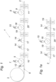
- a device 1 for carrying out the coil coating process according to the invention is shown, in which an endless metal strip 2, for example a steel strip (galvanized/ungalvanized), is unwound from a coil 3 and continuously coated with a multi-layer coating 4 as it passes through the strip (see the Figures 3 ).
- an endless metal strip 2 for example a steel strip (galvanized/ungalvanized)
- a multi-layer coating 4 as it passes through the strip
- a curable polymeric primer 7 is applied to a flat side 6 of the metal strip 2 in order to produce a primer layer 7.1 on this flat side 6.
- the primer 7 can, for example, have a polyester base. This is known to the adhesive strength and/or corrosion protection of the metal strip 2 is increased.
- a curable polymeric lacquer 8 which also has a polyester base, for example, is then applied to the primer layer 7.1 on the flat side 6 of the metal strip 2 to form a top coat layer 8.1.
- This application takes place - in the same way as shown for the primer application - using a roller 9 of a coater (not shown).
- the applied primer 7 and the applied lacquer 8 are each hardened by a dryer 10, 11 and/or hardened by chemical cross-linking.
- the metal strip 2 is electrochromically functionalized.
- an electrochromic element 13 is applied between the primer layer 7.1 and the top coat layer 8.1 in the coil coating process - namely, an electrically conductive, electrochromic polymer 14 and a solid polymer electrolyte 15 are applied in the coil coating process.
- the electrically conductive, electrochromic polymer 14 is printed with a printer 17 (e.g.: by digital printing, screen printing, gravure printing, etc.).
- the electrically conductive, electrochromic polymer 14 forms an electrochromic layer 14.1 or ion storage layer 14.2 on the metal strip 2, each with a layer thickness of 400 nm.
- the solid polymer electrolyte 15 is also printed on the metal strip 2 using the coil coating method - with the help of a coater (not shown) that produces an electrolyte layer 15.1 on the metal strip 2 using a roller 16 using a roll-to-roll method ("roll-to-roll").
- the electrically conductive, electrochromic polymer 14 comprises PEDOT:PSS [poly(3,4-ethylenedioxythiophene) polystyrene sulfonate] and optionally also a solvent (eg: H 2 O and/or isopropanol-based).
- a solvent eg: H 2 O and/or isopropanol-based.
- the solid polymer electrolyte 15 is prepared from a mixture of PVC-PMMA [poly(vinyl chloride)-poly(methyl methacrylate)] as electrolyte carrier and LiCF 3 SO 3 [lithium trifluoromethanesulfonate] as electrolyte salt with 18 weight percent PVC, 42 weight percent PMMA and 40 weight percent LiCF 3 SO 3. This mixture is dissolved in THF (tetrahydrofuran) at a ratio of 1 to 9.
- THF tetrahydrofuran
- PVDF-HFP poly(vinylidene fluoride-hexafluoropropylene)
- LiCF 3 SO 3 lithium trifluoromethanesulfonate
- electrolyte salt with 77 weight percent electrolyte carrier and 23 weight percent electrolyte salt
- solid polymer electrolyte 15 This mixture with 1.3 g can be dissolved in 6 g of NMP (N-methyl-2-pyrrolidone).
- NMP N-methyl-2-pyrrolidone
- an electrochromic polymer 14 is printed for each of the electrochromic layers 14.1 and the ion storage layer 14.2. It is conceivable that only one printer 17 is used to print the two layers 14.1, 14.2. Since the electrochromic polymer 14 is also electrically conductive, the electrochromic layer 14.1 and the ion storage layer 14.2 simultaneously form the electrodes or the first electrode 22.1 and second electrode 22.2 of the electrochromic element 13 - as shown in Fig. 2 can be recognized.
- the Fig. 3 It can be seen that the electrochromic layer 14.1 and the ion storage layer 14.2 are provided next to each other on the metal strip 2.
- the electrolyte layer 15.1 is applied wet to these two layers 14.1, 14.2, whereby the electrochromic layer 14.1 and the ion storage layer 14.2 are still wet in order to be able to guarantee the advantages according to the invention at both boundary layers 18.1, 18.2 or joining surfaces.
- the solid polymer electrolyte 15 also contains a solvent, namely tetrahydrofuran.
- Electrochromic layer 14.1, ion storage layer 14.2 and solid electrolyte layer 15.1 can be pre-cured as done by the dryers 19, 20 in the Figures 1 and 1a is indicated.
- Pre-curing the electrochromic layer 14.1 and/or ion storage layer 14.2 can facilitate the application/printing of the electrolyte layer 15.1 (cf. Fig. 1 ).
- pre-curing of the electrolyte layer 15.1 can facilitate the application/printing of the electrochromic layer 14.1 or ion storage layer 14.2 (cf. Fig. 1a ).
- the layer 14.1, 14.2 or 15.1 is pre-cured before the wet application of the other layer 14.1, 14.2 or 15.1 in such a way that this pre-cured layer has a viscosity measured in DIN cup 4 according to DIN 53211 in the range of 30 to 125 seconds [s] at 20°C.
- this pre-cured layer has a viscosity measured in DIN cup 4 according to DIN 53211 in the range of 30 to 125 seconds [s] at 20°C.
- wet-on-wet application of the respective layers can be ensured in a reproducible manner - and in particular the influence of the interface between the wet-on-wet layers can be further optimized.
- FIG. 4 an alternative embodiment of an electrochromic element 21 is disclosed: This electrochromic element 21 is applied to the metal strip 2 with a device 1, which device 1 in the electrochromic functionalization according to Fig. 1a In contrast to the Fig. 1 The electrochromic functionalization shown is carried out according to Fig. 1a the application of the electrolyte layer 15.1 in the belt passage between the application of the ion storage layer 14.2 and the electrochromic layer 14.1.
- the electrochromic element 21 can be Fig. 4 This vertical structure of the electrochromic element 21 is shown in Fig. 4 This can be seen from the fact that, as seen from the metal strip 2, the electrolyte layer 15.1 is applied or printed onto the ion storage layer 14.2 and the electrochromic layer 14.1 is applied or printed onto the electrolyte layer 15.1.
- both the ion storage layer 14.2 and the electrolyte layer 15.1 as well as the electrolyte layer 15.1 and the electrochromic layer 14.1 are applied or printed wet-on-wet.
Landscapes
- Physics & Mathematics (AREA)
- Nonlinear Science (AREA)
- Life Sciences & Earth Sciences (AREA)
- Engineering & Computer Science (AREA)
- Wood Science & Technology (AREA)
- General Physics & Mathematics (AREA)
- Optics & Photonics (AREA)
- Electrochromic Elements, Electrophoresis, Or Variable Reflection Or Absorption Elements (AREA)
Description
- Die Erfindung betrifft ein endloses Metallband und ein Coil-Coating-Verfahren zur mehrschichtigen Beschichtung eines endlosen Metallbands, bei welchem auf eine Flachseite des Metallbands mithilfe eines Walzenauftrags eine aushärtbare polymere Grundierung zur Ausbildung einer Grundierungsschicht und auf diese Grundierungsschicht mithilfe eines Walzenauftrags ein aushärtbarer polymerer Lack zur Ausbildung einer Decklackschicht aufgebracht und diese Grundierungsschicht und Decklackschicht gehärtet werden.
- Eine kontinuierliche Metallbandbeschichtung bzw. Coil-Coating-Verfahren zur mehrschichtigen Beschichtung eines sich im Banddurchlauf befindlichen endlosen Metallbands ist aus dem Stand der Technik bekannt (
DE102005061319A1 ). Bei solchen Verfahren wird an einer Flachseite des Metallbands meist eine Konversionsschicht erzeugt, nachfolgend auf diese Flachseite mithilfe eines Walzenauftrags eine aushärtbare polymere Grundierung zur Ausbildung einer Grundierungsschicht und auf diese Grundierungsschicht mithilfe eines Walzenauftrags ein aushärtbarer polymerer Lack zur Ausbildung einer Lackschicht aufgebracht und ausgehärtet. Derartige bekannte Verfahren können auch zur Funktionalisierung von Metallbändern dienen. - Die
EP2607950A1 offenbart ein Verfahren zur elektrochemischen Funktionalisierung eines Substrats, bei dem Elektrolytsegmente auf eine Pixelelektrodenschicht gedruckt werden. - Zur elektrischen Funktionalisierung eines Metallbands im Coil-Coating-Verfahren ist es aus der
EP2605280A1 bekannt, zwischen einer elektrisch isolierenden Grundierung auf dem Metallband und einer Decklackschicht auf der Grundierung zwei endlose elektrische Leiterbahnen sowie mit diesen kontaktierte photovoltaische Zellen vorzusehen. Grundierung und Decklacksicht werden mithilfe eines Walzenauftrags aufgetragen. - Ausgehend vom eingangs geschilderten Stand der Technik hat sich die Erfindung die Aufgabe gestellt, ein Coil-Coating-Verfahren zu schaffen, das reproduzierbar eine standfeste elektrochrome Funktionalisierung eines Metallbands mit verbesserten elektrochromen und mechanischen Eigenschaften sicherstellen kann. Zudem soll das Coil-Coating-Verfahren besonders einfach und daher kostengünstig anwendbar sein.
- Die Erfindung löst die gestellte Aufgabe dadurch, dass zwischen Grundierungsschicht und Decklackschicht mindestens ein elektrochromes Element aufgebracht wird, umfassend die Verfahrensschritte Drucken eines, insbesondere elektrisch leitfähigen, elektrochromen Polymers zur Ausbildung einer elektrochromen Schicht und/oder lonenspeicherschicht und Vorsehen eines festen Polymerelektrolyten zur Ausbildung einer Elektrolytschicht, wobei die Elektrolytschicht und die elektrochrome Schicht oder die ionenspeicherschicht nass-in-nass aufgebracht werden.
- Wird zwischen Grundierungsschicht und Lackschicht mindestens ein elektrochromes Element aufgebracht, kann dem Metallband bereits mit einem Coil-Coating Verfahren eine elektrochrome Funktionalität gegeben werden, wenn dieses Aufbringen die Verfahrensschritte Drucken eines, insbesondere elektrisch leitfähigen, elektrochromen Polymers zur Ausbildung einer elektrochromen Schicht und/oder lonenspeicherschicht und Vorsehen eines festen Polymerelektrolyten zur Ausbildung einer Elektrolytschicht umfasst. Das Aufbringen dieser Schichten bedarf beim Coil-Coating Verfahren besonderer Sorgfalt, um mit vergleichsweise hoher Reproduzierbarkeit die gewünschten elektrochromen Eigenschaften am elektrochromen Element sicherstellen zu können.
- Um diese Reproduzierbarkeit zu ermöglichen, schlägt die Erfindung vor, dass die Elektrolytschicht und die elektrochrome Schicht und/oder die ionenspeicherschicht nass-in-nass aufgebracht werden. Damit kann beispielsweise gewährleistet werden, die Elektrolytschicht an einer unausgehärteten elektrochromen Schicht oder unausgehärteten lonenspeicherschicht bzw. die elektrochrome Schicht oder lonenspeicherschicht an der unausgehärteten Elektrolytschicht vorzusehen - wodurch sich diese Schichten an der Fügefläche verbessert verbinden können. Ein elektrochromes Element mit vergleichsweise hoher mechanischer Belastbarkeit kann damit reproduzierbar hergestellt werden. Zudem können durch das Nass-in-nass-Aufbringen eventuelle Unebenheiten an der Grenzfläche zwischen den Schichten geglättet werden - lokale Spannungsspitzen durch Unebenheiten an der Grenzfläche sind somit einfach vermeidbar. Die Degradation der Schichten kann auf diese Weise verlangsamt werden, was die reproduzierbare Herstellung eines elektrochromen Elements mit vergleichsweise großer Zahl von Schaltzyklen ohne nennenswerten Abfall der elektrochromen Eigenschaften ermöglichen kann. Zudem kann solch eine durch das nass-in-nass Aufbringen entstehende glatte Grenzfläche reproduzierbar ein elektrochromes Element sowohl mit homogenem Kontrast als auch mit homogenem Umschaltverhalten zulassen.
- Im Allgemeinen wird erwähnt, dass das Metallband aus Eisen oder Aluminium bzw. aus deren Legierungen bestehen kann. Dieses Metallband kann unbeschichtet oder beschichten - z. B. organisch/metallisch, verzinkt oder legierungsverzinkt - sein. Auch kann dieses Metallband ein verzinktes oder legierungsverzinktes Stahlband sein. Im Allgemeinen wird weiter erwähnt, dass vorgesehen sein kann, die jeweiligen Schichten derart nass-in-nass aufzubringen, dass dabei ein Fließen der beiden Schichten zumindest an ihren gemeinsamen Grenzfläche zugelassen wird. Dies bedeutet, dass auf eine nicht vollständig getrocknete, also eventuell zwischengetrocknete/abgelüftete, bzw. noch nicht vollständig ausgehärtete / unausgehärtete Schicht eine andere nasse Schicht trifft, um damit ein "nass-in-nass"-Aufragen zu ermöglichen.
- Das Verfahren kann weiter vereinfacht werden, wenn zur Ausbildung der elektrochromen Schicht und der lonenspeicherschicht jeweils ein elektrochromes Polymer gedruckt werden.
- Ein vertikal aufgebautes elektrochromes Element kann besonders einfach hergestellt werden, wenn die lonenspeicherschicht, die Elektrolytschicht und die die elektrochrome Schicht übereinander aufgebracht werden. Als besonders vorteilhaft kann sich zeigen, diese Schichten hierzu zu drucken. Im Allgemeinen wird erwähnt, dass eine verbesserte elektrochrome Funktionalität am elektrochromen Element erreicht werden kann, wenn - vom Metallband aus gesehen - auf die lonenspeicherschicht die Elektrolytschicht und auf die Elektrolytschicht die elektrochrome Schicht aufgebracht, insbesondere gedruckt, werden.
- Zu einem einfachen Fertigungsprozess im Coil-Coating-Verfahren kann beitragen, wenn der feste Polymerelektrolyt gedruckt wird. Vorzugsweise kann hierzu ein Rolle-zu-Rolle-Verfahren Anwendung finden, um hohe Bandgeschwindigkeiten sicherstellen zu können.
- Wird das elektrochrome Polymer mit mindestens einem Lösungsmittel aufgetragen, kann selbst bei vergleichsweise schnellen Bandlaufgeschwindigkeiten eine ausreichend feuchte Polymermasse für einen nass-in-nass Auftrag im Coil-Coating Verfahren sichergestellt werden. Verfahrenstechnisch einfach gelöst, kann zu diesem Zweck H2O als Lösungsmittel verwendet werden.
- Vorstehend Erwähntes kann auch bei einem festen Polymerelektrolyt ermöglicht werden, wenn dieser feste Polymerelektrolyt mit mindestens einem Lösungsmittel, insbesondere Tetrahydrofuran, aufgetragen wird. Auch NMP (N-Methyl-2-pyrrolidon) kann sich diesbezüglich auszeichnen.
- Der Fertigungsprozess zum elektrochromen Element kann im Coil-Coating-Verfahren weiter verbessert werden, wenn die elektrochrome Schicht und/oder lonenspeicherschicht und/oder die Elektrolytschicht aktiv vorgehärtet werden, bevor die jeweils andere Schicht des elektrochromen Elements aufgebracht wird. Dies kann insbesondere ein Druckverfahren mit einem Rolle-zu-Rolle-Auftrag erleichtern - und damit die Reproduzierbarkeit des Verfahrens weiter erhöhen.
- Das Aufdrucken einer nassen Schicht kann insbesondere dann reproduzierbar sichergestellt werden, wenn bis zu einer Viskosität im Bereich von 30 bis 125 Sekunden [s], gemessen im DIN-Becher 4 gemäß DIN 53211 bei 20°C (Grad Celsius), vorgehärtet wird.
- Ein besonders einfach herzustellendes elektrochromes Element mit hervorragenden elektrochromen Eigenschaften kann geschaffen werden, wenn das elektrisch leitfähige, elektrochrome Polymer PEDOT:PSS [poly(3,4-ethylenedioxythiophene) polystyrene sulfonate] aufweist.
- Die Applikation des Polymerelektrolyts im Coil-Coating Verfahren kann weiter erleichtert werden, wenn der feste Polymerelektrolyt als Elektrolytträger PVDF-HFP [poly(vinylidenefluorid-hexafluoropropylen)] oder PVC-PMMA [poly(vinylchlorid)-poly(methylmethacrylat)] aufweist.
- Weist der feste Polymerelektrolyt als Elektrolytsalz ein Alkalimetallsalz, insbesondere LiCF3SO3 [Lithiumtrifluoromethansulfonat], auf, kann dies die Reproduzierbarkeit des Verfahrens zusätzlich erhöhen.
- Das gedruckte elektrochrome Polymer kann zu einer Schichtdicke von 50 nm bis 1 µm, vorzugsweise 200 bis 500 nm, und insbesondere 200 nm bis 600 nm führen, um die elektrochrome Funktionalisierung des Metallbands zu verbessern.
- Es ist zudem Aufgabe der Erfindung, ein endloses Metallband mit einem elektrochromen Element zu schaffen, das eine hohe mechanische und elektrochrome Eigenschaften aufweist.
- Die Erfindung löst diese gestellte Aufgabe durch ein endloses Metallband mit einer Grundierungsschicht, mit einer Decklackschicht und mit einem zwischen Grundierungsschicht und Decklackschicht vorgesehenen elektrochromen Element, das eine erste Elektrode, eine elektrochrome Schicht, eine feste Elektrolytschicht, eine lonenspeicherschicht und eine zweite Elektrode aufweist, wobei ein erstes elektrisch leitfähiges, elektrochromes Polymer sowohl die erste Elektrode als auch die elektrochrome Schicht und ein zweites elektrisch leitfähiges, elektrochromes Polymer sowohl die lonenspeicherschicht als auch die zweite Elektrode ausbildet.
- Indem die Elektrolytschicht und die elektrochrome Schicht und/oder die lonenspeicherschicht des elektrochromen Elements nass-in-nass aufgebracht werden, kann nicht nur die mechanische Festigkeit der Schichten an der gemeinsamen Fügefläche verbessert, sondern auch vorteilhaft die Grenzfläche zwischen diesen Schichten geglättet werden, was die elektrochromen Eigenschaften des elektrochromen Elements verbessert. So ist mit einer verminderten Degradation der Schichten und damit einer erhöhten Lebensdauer des elektrochromen Elements als auch mit einem homogeneren Kontrast und einem homogenen Umschaltverhalten zu rechnen. Eine mechanisch besonders standfeste bzw. eine verbesserte elektrochrome Funktionalisierung eines Metallbands kann damit ermöglicht werden.
- Im Allgemeinen wird erwähnt, dass die Elektrolytschicht und die elektrochrome Schicht und/oder die lonenspeicherschicht beispielsweise über eine sich durch ein Nass-in-nass-Aufbringen dieser Schichten zwischen diesen ausbildenden, geglätteten Grenzfläche anschließen können.
- Die mechanische Standfestigkeit und die elektrochrome Funktionalisierung können weiter verbessert werden, wenn das elektrisch leitfähige, elektrochrome Polymer PEDOT:PSS aufweist und/oder der feste Polymerelektrolyt als Elektrolytträger PVDF-HFP oder PVC-PMMA aufweist. Hierzu kann beitragen, wenn der feste Polymerelektrolyt als Elektrolytsalz ein Alkalimetallsatz, insbesondere LiCF3SO3, aufweist.
- In den Figuren ist beispielsweise der Erfindungsgegenstand anhand mehrerer Ausführungsvarianten näher dargestellt. Es zeigen
- Fig. 1
- eine schematische Ansicht auf eine Vorrichtung für ein Coil-Coating-Verfahren,
- Fig. 1a
- eine alternative Ausbildung der nach
Fig. 1 dargestellten Vorrichtung, - Fig. 2
- eine ab- und aufgerissene Draufsicht auf ein endloses Metallband nach einem ersten Ausführungsbeispiel - hergestellt nach dem nach
Fig. 1 dargestellten Coil-Coating-Verfahren, - Fig. 3
- eine Schnittansicht nach III-III der
Fig. 2 und - Fig. 4
- eine Schnittansicht eines anderen endloses Metallbands nach einem zweiten Ausführungsbeispiel.
- Gemäß
Fig. 1 wird eine Vorrichtung 1 zur Durchführung des erfindungsgemäßen Coil-Coating-Verfahrens gezeigt, bei welchem ein endloses Metallband 2, beispielsweise ein Stahlband (verzinkt/unverzinkt), von einem Coil 3 abgewickelt und im Banddurchlauf kontinuierlich mit einer mehrschichtigen Beschichtung 4 (siehe hierzu dieFiguren 3 ) versehen wird. - Mithilfe einer Walze 5 eines nicht dargestellten Coaters, wird auf eine Flachseite 6 des Metallbands 2 eine aushärtbare polymere Grundierung 7 bzw. Primer aufgebracht, um auf dieser Flachseite 6 eine Grundierungsschicht 7.1 zu erzeugen. Die Grundierung 7 kann beispielsweise eine Polyesterbasis aufweisen. Damit wird bekanntermaßen die Haftfestigkeit am und/oder der Korrosionsschutz des Metallbands 2 erhöht.
- Auf die Grundierungsschicht 7.1 auf der Flachseite 6 des Metallbands 2 wird in weiterer Folge ein aushärtbarer polymerer Lack 8, der beispielsweise ebenso eine Polyesterbasis aufweist, zur Ausbildung einer Decklackschicht 8.1 aufgebracht. Dieses Aufbringen erfolgt - gleichwie beim Grundierungsauftrag dargestellt - mithilfe einer Walze 9 eines nicht dargestellten Coaters. Die aufgetragene Grundierung 7 und der aufgetragene Lack 8 werden jeweils durch einen Trockner 10, 11 gehärtet und/oder durch chemisches Vernetzen gehärtet.
- Vor dem Aufbringen der Grundierungsschicht 7.1 auf der oberen Flachseite 6 des Metallbands 2, ist es vorstellbar, dass ein Sol-Gel 12 aufgesprüht wird, um eine Konversionssicht zu erzeugen.
- Erfindungsgemäße wird das Metallband 2 elektrochrom funktionalisiert. Hierzu wird im Coil-Coating-Verfahren zwischen Grundierungsschicht 7.1 und Decklackschicht 8.1 ein elektrochromes Element 13 appliziert - und zwar wird ein elektrisch leitfähiges, elektrochromes Polymer 14 und ein festes Polymerelektrolyt 15 im Coil-Coating-Verfahren aufgetragen.
- Hierbei wird das elektrisch leitfähige, elektrochrome Polymer 14 mit einem Drucker 17 aufgedruckt (z.B.: durch Digitaldruck, Siebdruck, Tiefdruck etc.). Das elektrisch leitfähige, elektrochrome Polymer 14 bildet auf dem Metallband 2 eine elektrochromen Schicht 14.1 oder lonenspeicherschicht 14.2 aus, je mit einer Schichtdicke von 400 nm. Ebenso wird der feste Polymerelektrolyt 15 im Coil-Coating-Verfahren auf das Metallband 2 gedruckt - und zwar mithilfe eines nicht dargestellten Coaters, der mit einer Walze 16 über ein Rolle-zu-Rolle-Verfahren ("Roll-to-Roll") auf dem Metallband 2 eine Elektrolytschicht 15.1 erzeugt.
- Das elektrisch leitfähige, elektrochrome Polymer 14 weist PEDOT:PSS [poly(3,4-ethylenedioxythiophene) polystyrene sulfonate] und gegebenenfalls auch ein Lösungsmittel (z.B.: H2O und/oder Isopropanolbasis) auf. Die Druckbarkeit solch eines elektrisch leitfähigen, elektrochromen Polymers 14 kann verbessert werden, wenn PEDOT:PSS als wässrige und/oder Isopropanol-basierte Dispersion aufgetragen wird.
- Der feste Polymerelektrolyt 15 wird aus einer Mischung von PVC-PMMA [poly(vinylchlorid)-poly(methylmethacrylat)] als Elektrolytträger und LiCF3SO3 [Lithiumtrifluoromethansulfonat] als Elektrolytsalz mit 18 Gewichtsprozent PVC, 42 Gewichtsprozent PMMA und 40 Gewichtsprozent LiCF3SO3 hergestellt. Diese Mischung wird mit einem Verhältnis von 1 zu 9 in THF (Tetrahydrofuran) gelöst.
- Als festes Polymerelektrolyt 15 ist außerdem eine Mischung von PVDF-HFP [poly(vinylidenefluorid-hexafluoropropylen)] als Elektrolytträger und LiCF3SO3 [Lithiumtrifluoromethansulfonat] als Elektrolytsalz mit 77 Gewichtsprozent Elektrolytträger und 23 Gewichtsprozent Elektrolytsalz vorstellbar. Diese Mischung mit 1,3 g kann in 6g in NMP (N-Methyl-2-pyrrolidon) gelöst sein. Der aufgebrachte feste Polymerelektrolyt 15 führt zu einer Schichtdicke im Bereich zwischen 2,7 und 13,5 µm.
- Hervorragende elektrochrome und mechanische Eigenschaften am elektrochromen Element 13 werden dadurch sicherstellt, dass die Elektrolytschicht 15.1 und die elektrochrome Schicht 14.1 oder die lonenspeicherschicht 14.2 nass-in-nass aufgebracht werden. Um dies zu erreichen, ist eine dieser Schichten 14.1, 14.2 oder 15.1 noch feucht bzw. nass und damit nicht vollständig gehärtet - auf welche die jeweils andere nasse Schicht 14.1, 14.2 oder 15.1 appliziert wird. Auf diese Weise kann ein Fließen zumindest jener Schichten, auf welche nass aufgebracht wird, ermöglicht werden, wodurch eventuelle Unebenheiten geglättet und eine glatte Grenzfläche 18.1 bzw. 18.2 zwischen den betreffenden Schichten 14.1, 14.2 oder 15.1 sichergestellt wird. Dies reduziert die Degradation am elektrochromen Element 13, wodurch sich eine vergleichsweise große Zahl von Schaltzyklen ohne nennenswerten Abfall der elektrochromen Eigenschaften ergibt. Auch können damit am elektrochromen Element 13 ein homogener Kontrast und ein homogenes Umschaltverhalten ermöglicht werden - wobei diese Art des stoffschlüssigen Fügens an der Grenzfläche 18.1 bzw. 18.2 bzw. damit auch der Fügefläche eine hohe Haftfestigkeit gewährleistet und zu einer hohen Standfestigkeit am elektrochromen Element 13 führt.
- Wie insbesondere in
Fig. 1 zu erkennen, wird je ein elektrochromes Polymer 14 für die elektrochromen Schicht 14.1 und der lonenspeicherschicht 14.2 gedruckt. Hierbei ist vorstellbar, dass zum Drucken der beiden Sichten 14.1, 14.2 nur ein Drucker 17 verwendet wird. Da das elektrochrome Polymer 14 auch elektrisch leitend ist, bilden die elektrochrome Schicht 14.1 und die lonenspeicherschicht 14.2 auch gleichzeitig die Elektroden bzw. die erste Elektrode 22.1 und zweite Elektrode 22.2 des elektrochromen Elements 13 aus - wie dies inFig. 2 zu erkennen ist. - Der
Fig. 3 ist zu entnehmen, dass die elektrochrome Schicht 14.1 und die lonenspeicherschicht 14.2 nebeneinander auf dem Metallband 2 vorgesehen sind. Die Elektrolytschicht 15.1 wird auf diese beiden Schichten 14.1, 14.2 nass appliziert, wobei dabei die elektrochrome Schicht 14.1 und die lonenspeicherschicht 14.2 noch nass sind, um an beiden Grenzschichten 18.1, 18.2 bzw. Fügeflächen die erfindungsgemäßen Vorteile gewährleisten zu können. - Der feste Polymerelektrolyt 15 weist ebenso ein Lösungsmittel, nämlich Tetrahydrofuran, auf.
- Elektrochrome Schicht 14.1, lonenspeicherschicht 14.2 und feste Elektrolytschicht 15.1 können vorgehärtet werden, wie dies durch die Trockner 19, 20 in den
Figuren 1 und 1a angedeutet ist. - Das Vorhärten der elektrochromen Schicht 14.1 und/oder lonenspeicherschicht 14.2 kann das Aufbringen/Drucken der Elektrolytschicht 15.1 erleichtern (vgl.
Fig. 1 ). - Zudem kann ein Vorhärten der Elektrolytschicht 15.1 das Aufbringen/Drucken der elektrochrome Schicht 14.1 oder lonenspeicherschicht 14.2 erleichtern (vgl.
Fig. 1a ). - Die Schicht 14.1, 14.2 bzw. 15.1 wird vor dem nassen Aufbringen der jeweils anderen Schicht 14.1, 14.2 bzw. 15.1 derart vorgehärtet, dass diese vorgehärtete Schicht eine im DIN-Becher 4 gemäß DIN 53211 gemessene Viskosität im Bereich von 30 bis 125 Sekunden [s] bei 20°C aufweist. Auf diese Weise kann reproduzierbar ein Nass-in-nass-Aufbringen der jeweiligen Schichten gewährleistet - und ganz besonders der Einfluss der Grenzfläche zwischen den nass-in-nass aufgebrachten Schichten weiter optimiert werden. Zudem ist es damit möglich, ein nasses Aufdrucken der jeweiligen anderen Schicht (elektrochrome Schicht 14.1, lonenspeicherschicht 14.2 und feste Elektrolytschicht 15.1) reproduzierbar zu ermöglichen.
- In der
Fig. 4 ist eine alternative Ausführung eines elektrochromen Elements 21 geoffenbart: Dieses elektrochrome Element 21 wird mit einer Vorrichtung 1 auf das Metallband 2 appliziert, welche Vorrichtung 1 in der elektrochromen Funktionalisierung entsprechendFig. 1a konstruktiv verändert ist. Zum Unterschied zur nachFig. 1 dargestellten elektrochromen Funktionalisierung erfolgt gemäßFig. 1a der Auftrag der Elektrolytschicht 15.1 im Banddurchlauf zwischen dem Auftrag der lonenspeicherschicht 14.2 und der elektrochrome Schicht 14.1. - Durch diese konstruktive Änderung an der Vorrichtung bzw. durch diese Verfahrensänderung kann das elektrochrome Element 21 nach
Fig. 4 vertikal hergestellt werden. Dieser vertikale Aufbau des elektrochromen Elements 21 ist inFig. 4 daran zu erkennen, dass vom Metallband 2 aus gesehen auf die lonenspeicherschicht 14.2 die Elektrolytschicht 15.1 und auf die Elektrolytschicht 15.1 die elektrochrome Schicht 14.1 aufgebracht bzw. gedruckt wird. - Vorzugsweise werden sowohl lonenspeicherschicht 14.2 als auch die Elektrolytschicht 15.1 sowie die Elektrolytschicht 15.1 und die elektrochrome Schicht 14.1 nass-in-nass aufgebracht bzw. gedruckt.
Claims (16)
- Coil-Coating-Verfahren zur mehrschichtigen Beschichtung eines endlosen Metallbands (2), bei welchemauf eine Flachseite (6) des Metallbands (2) mithilfe eines Walzenauftrags eine aushärtbare polymere Grundierung (7) zur Ausbildung einer Grundierungsschicht (7.1) undauf diese Grundierungsschicht (7.1) mithilfe eines Walzenauftrags ein aushärtbarer polymerer Lack (8) zur Ausbildung einer Decklackschicht (8.1) aufgebracht und diese Grundierungsschicht (7.1) und Decklackschicht (8.1) gehärtet werden,
dadurch gekennzeichnet, dasszwischen Grundierungsschicht (7.1) und Decklackschicht (8.1) mindestens ein elektrochromes Element (13, 21) aufgebracht wird, umfassend die VerfahrensschritteDrucken eines, insbesondere elektrisch leitfähigen, elektrochromen Polymers (14) zur Ausbildung einer elektrochromen Schicht (14.1) und/oder lonenspeicherschicht (14.2) undVorsehen eines festen Polymerelektrolyten (15) zur Ausbildung einer Elektrolytschicht (15.1), wobei die Elektrolytschicht (15.1) und die elektrochrome Schicht (14.1) oder die lonenspeicherschicht (14.2) nass-in-nass aufgebracht werden. - Coil-Coating-Verfahren nach Anspruch 1, dadurch gekennzeichnet, dass zur Ausbildung der elektrochromen Schicht (14.1) und der lonenspeicherschicht (14.2) jeweils ein elektrochromes Polymer (14) gedruckt werden.
- Coil-Coating-Verfahren nach Anspruch 1 oder 2, dadurch gekennzeichnet, dass die lonenspeicherschicht (14.2), die Elektrolytschicht (15.1) und die die elektrochrome Schicht (14.1) übereinander aufgebracht, insbesondere gedruckt, werden.
- Coil-Coating-Verfahren nach Anspruch 1, 2 oder 3, dadurch gekennzeichnet, dass der feste Polymerelektrolyt (15), insbesondere mithilfe eines Rolle-zu-Rolle-Verfahrens, gedruckt wird.
- Coil-Coating-Verfahren nach einem der Ansprüche 1 bis 4, dadurch gekennzeichnet, dass das elektrochrome Polymer (14) mit mindestens einem Lösungsmittel, insbesondere H2O, aufgetragen wird.
- Coil-Coating-Verfahren nach einem der Ansprüche 1 bis 5, dadurch gekennzeichnet, dass der feste Polymerelektrolyt (15) mit mindestens einem Lösungsmittel, insbesondere THF (Tetrahydrofuran) oder NMP (N-Methyl-2-pyrrolidon), aufgetragen wird.
- Coil-Coating-Verfahren nach Anspruch 5 oder 6, dadurch gekennzeichnet, dass die elektrochrome Schicht (14.1) und/oder lonenspeicherschicht (14.2) und/oder die Elektrolytschicht (15.1) aktiv vorgehärtet werden, bevor die jeweils andere Schicht des elektrochromen Elements (13, 21) aufgebracht wird.
- Coil-Coating-Verfahren nach Anspruch 7, dadurch gekennzeichnet, dass bis zu einer Viskosität im Bereich von 30 bis 125 Sekunden [s], gemessen im DIN-Becher 4 gemäß DIN 53211, vorgehärtet wird.
- Coil-Coating-Verfahren nach einem der Ansprüche 1 bis 8, dadurch gekennzeichnet, dass das elektrisch leitfähige, elektrochrome Polymer (14) PEDOT:PSS aufweist.
- Coil-Coating-Verfahren nach einem der Ansprüche 1 bis 9, dadurch gekennzeichnet, dass der feste Polymerelektrolyt (15) als Elektrolytträger PVDF-HFP oder PVC-PMMA aufweist.
- Coil-Coating-Verfahren nach Anspruch 10, dadurch gekennzeichnet, dass der feste Polymerelektrolyt (15) als Elektrolytsalz ein Alkalimetallsatz, insbesondere LiCF3SO3, aufweist.
- Coil-Coating-Verfahren nach einem der Ansprüche 1 bis 11, dadurch gekennzeichnet, dass das gedruckte elektrochrome Polymer (14) zu einer Schichtdicke von 50 nm bis 1 µm, vorzugsweise 200 bis 500 nm, und insbesondere 200 nm bis 600 nm führt.
- Endloses Metallband, hergestellt durch ein Verfahren nach einem der Ansprüche 1 bis 12 mit einer Grundierungsschicht (7.1), mit einer Decklackschicht (8.1) und mit einem zwischen Grundierungsschicht (7.1) und Decklackschicht (8.1) vorgesehenen elektrochromen Element (13, 21), das eine erste Elektrode (22.1), eine elektrochrome Schicht (14.1), eine feste Elektrolytschicht (15.1), eine lonenspeicherschicht (14.2) und eine zweite Elektrode (22.2) aufweist, wobei ein erstes elektrisch leitfähiges, elektrochromes Polymer (14) sowohl die erste Elektrode (22.1) als auch die elektrochrome Schicht (14.1) und ein zweites elektrisch leitfähiges, elektrochromes Polymer (14) sowohl die lonenspeicherschicht (14.2) als auch die zweite Elektrode (22.2) ausbildet.
- Endloses Metallband nach Anspruch 13, dadurch gekennzeichnet, dass das elektrisch leitfähige, elektrochrome Polymer (14) PEDOT:PSS aufweist.
- Endloses Metallband nach Anspruch 13 oder 14, dadurch gekennzeichnet, dass der feste Polymerelektrolyt (15) als Elektrolytträger PVDF-HFP oder PVC-PMMA aufweist.
- Endloses Metallband nach Anspruch 15, dadurch gekennzeichnet, dass der feste Polymerelektrolyt (15) als Elektrolytsalz ein Alkalimetallsatz, insbesondere LiCF3SO3, aufweist.
Applications Claiming Priority (2)
| Application Number | Priority Date | Filing Date | Title |
|---|---|---|---|
| EP16183649.9A EP3281710A1 (de) | 2016-08-10 | 2016-08-10 | Coil-coating-verfahren und metallband |
| PCT/EP2017/070389 WO2018029323A1 (de) | 2016-08-10 | 2017-08-10 | Endloses metallband und coil-coating-verfahren zur mehrschichtigen beschichtung dieses endlosen metallbands |
Publications (2)
| Publication Number | Publication Date |
|---|---|
| EP3496872A1 EP3496872A1 (de) | 2019-06-19 |
| EP3496872B1 true EP3496872B1 (de) | 2024-12-11 |
Family
ID=56799247
Family Applications (2)
| Application Number | Title | Priority Date | Filing Date |
|---|---|---|---|
| EP16183649.9A Withdrawn EP3281710A1 (de) | 2016-08-10 | 2016-08-10 | Coil-coating-verfahren und metallband |
| EP17761820.4A Active EP3496872B1 (de) | 2016-08-10 | 2017-08-10 | Endloses metallband und coil-coating-verfahren zur mehrschichtigen beschichtung dieses endlosen metallbands |
Family Applications Before (1)
| Application Number | Title | Priority Date | Filing Date |
|---|---|---|---|
| EP16183649.9A Withdrawn EP3281710A1 (de) | 2016-08-10 | 2016-08-10 | Coil-coating-verfahren und metallband |
Country Status (3)
| Country | Link |
|---|---|
| EP (2) | EP3281710A1 (de) |
| PL (1) | PL3496872T3 (de) |
| WO (1) | WO2018029323A1 (de) |
Families Citing this family (1)
| Publication number | Priority date | Publication date | Assignee | Title |
|---|---|---|---|---|
| US10983408B2 (en) | 2018-12-17 | 2021-04-20 | Furcifer Inc. | Display device with electrochromic material |
Family Cites Families (7)
| Publication number | Priority date | Publication date | Assignee | Title |
|---|---|---|---|---|
| US6936761B2 (en) * | 2003-03-29 | 2005-08-30 | Nanosolar, Inc. | Transparent electrode, optoelectronic apparatus and devices |
| DE102005061319A1 (de) | 2005-12-20 | 2007-06-21 | Basf Ag | Verfahren zum Aufbringen von Korrosionsschutzschichten umfassend Thioamide auf metallische Oberflächen |
| US20100015329A1 (en) * | 2008-07-16 | 2010-01-21 | National Semiconductor Corporation | Methods and systems for packaging integrated circuits with thin metal contacts |
| US20110143019A1 (en) * | 2009-12-14 | 2011-06-16 | Amprius, Inc. | Apparatus for Deposition on Two Sides of the Web |
| DE102011121165A1 (de) | 2011-12-16 | 2013-06-20 | Thyssenkrupp Steel Europe Ag | Metallisches Bauelement oder Flacherzeugnis mit photovoltaisch wirksamer Beschichtung, Verfahren zu dessen Herstellung und aus solchen, miteinander elektrisch verschalteten Bauelementen gebildete Verkleidung |
| EP2607950B1 (de) * | 2011-12-22 | 2014-05-21 | Acreo Swedish ICT AB | Standbildanzeigevorrichtung und Verfahren zu ihrer Herstellung |
| PT106070A (pt) * | 2011-12-23 | 2013-06-24 | Yd Ynvisible S A | Solução de electrólito, método de impressão da mesma e electrólito sólido resultante |
-
2016
- 2016-08-10 EP EP16183649.9A patent/EP3281710A1/de not_active Withdrawn
-
2017
- 2017-08-10 EP EP17761820.4A patent/EP3496872B1/de active Active
- 2017-08-10 PL PL17761820.4T patent/PL3496872T3/pl unknown
- 2017-08-10 WO PCT/EP2017/070389 patent/WO2018029323A1/de not_active Ceased
Also Published As
| Publication number | Publication date |
|---|---|
| WO2018029323A1 (de) | 2018-02-15 |
| EP3281710A1 (de) | 2018-02-14 |
| EP3496872A1 (de) | 2019-06-19 |
| PL3496872T3 (pl) | 2025-03-31 |
Similar Documents
| Publication | Publication Date | Title |
|---|---|---|
| DE2741417A1 (de) | Grundplatte fuer eine gedruckte schaltung | |
| DE3700910A1 (de) | Verfahren zum aufbau elektrischer schaltungen auf einer grundplatte | |
| DE202018006859U1 (de) | Leitfähige Zusammensetzung und Leiter | |
| DE102008030441B3 (de) | Lichtventilanordnung mit schaltbarer Transparenz und Verfahren zu deren Herstellung | |
| DE2227751B2 (de) | Elektrischer Kondensator und Verfahren zu seiner Herstellung | |
| EP3594969B1 (de) | Verfahren zur herstellung eines mit elektroisolierlack beschichteten leiterdrahtes und elektroisolierlack | |
| DE102017001276B4 (de) | Verfahren und Vorrichtung zum Herstellen eines dreidimensionalen Formgegenstands mittels schichtweisem Materialauftrag | |
| EP3060031B1 (de) | Coil-coating-verfahren | |
| WO2006048041A1 (de) | Flexibler träger mit elektrisch leitfähiger struktur | |
| DE19718859C2 (de) | Leitfähige bedruckbare Bahnen aus Kunststoff | |
| WO2018029323A1 (de) | Endloses metallband und coil-coating-verfahren zur mehrschichtigen beschichtung dieses endlosen metallbands | |
| EP1516375A2 (de) | Material für eine dünne und niedrig leitfähige funktionsschicht für eine oled und herstellungsverfahren dazu | |
| EP0554798A2 (de) | Beschichtungsmittel für Kunststofffolien | |
| WO2015104015A2 (de) | Sensorelement zur bestimmung von dehnungen | |
| AT516829B1 (de) | Coil-Coating-Verfahren | |
| DE102011004543B4 (de) | Widerstand, Leiterplatte und elektrisches oder elektronisches Gerät | |
| EP3395130B1 (de) | Metallband und coil-coating-verfahren | |
| DE102018004616B4 (de) | Biegbarer eletrischer Leiter in einem warmgeformten Gegenstand | |
| DE102020207597A1 (de) | Elektroaktive Faser, deren Herstellung und deren Anwendung in Textilien | |
| EP3454631B1 (de) | Verfahren zur herstellung eines elektrischen anschlusskontakts an einem beschichteten blech | |
| WO2024133951A1 (de) | Metallblech oder -band sowie verfahren zu dessen herstellung | |
| DE102023109417A1 (de) | Sensor | |
| DE102005035590A1 (de) | Elektronisches Bauelement | |
| AT510079A1 (de) | Verfahren zur herstellung von mehrschichtigen schaltungen und mehrschichtige schaltung | |
| EP4468818A1 (de) | Elektrische heizschicht und verfahren zu deren herstellung |
Legal Events
| Date | Code | Title | Description |
|---|---|---|---|
| STAA | Information on the status of an ep patent application or granted ep patent |
Free format text: STATUS: UNKNOWN |
|
| STAA | Information on the status of an ep patent application or granted ep patent |
Free format text: STATUS: THE INTERNATIONAL PUBLICATION HAS BEEN MADE |
|
| PUAI | Public reference made under article 153(3) epc to a published international application that has entered the european phase |
Free format text: ORIGINAL CODE: 0009012 |
|
| STAA | Information on the status of an ep patent application or granted ep patent |
Free format text: STATUS: REQUEST FOR EXAMINATION WAS MADE |
|
| 17P | Request for examination filed |
Effective date: 20190311 |
|
| AK | Designated contracting states |
Kind code of ref document: A1 Designated state(s): AL AT BE BG CH CY CZ DE DK EE ES FI FR GB GR HR HU IE IS IT LI LT LU LV MC MK MT NL NO PL PT RO RS SE SI SK SM TR |
|
| AX | Request for extension of the european patent |
Extension state: BA ME |
|
| DAV | Request for validation of the european patent (deleted) | ||
| DAX | Request for extension of the european patent (deleted) | ||
| STAA | Information on the status of an ep patent application or granted ep patent |
Free format text: STATUS: EXAMINATION IS IN PROGRESS |
|
| 17Q | First examination report despatched |
Effective date: 20201119 |
|
| P01 | Opt-out of the competence of the unified patent court (upc) registered |
Effective date: 20230515 |
|
| RIC1 | Information provided on ipc code assigned before grant |
Ipc: G02F 1/15 20060101ALN20240426BHEP Ipc: B05D 5/00 20060101ALN20240426BHEP Ipc: G02F 1/161 20060101ALI20240426BHEP Ipc: B05D 1/28 20060101ALI20240426BHEP Ipc: B05D 7/00 20060101ALI20240426BHEP Ipc: B05D 7/14 20060101AFI20240426BHEP |
|
| GRAP | Despatch of communication of intention to grant a patent |
Free format text: ORIGINAL CODE: EPIDOSNIGR1 |
|
| STAA | Information on the status of an ep patent application or granted ep patent |
Free format text: STATUS: GRANT OF PATENT IS INTENDED |
|
| INTG | Intention to grant announced |
Effective date: 20240607 |
|
| GRAS | Grant fee paid |
Free format text: ORIGINAL CODE: EPIDOSNIGR3 |
|
| GRAA | (expected) grant |
Free format text: ORIGINAL CODE: 0009210 |
|
| STAA | Information on the status of an ep patent application or granted ep patent |
Free format text: STATUS: THE PATENT HAS BEEN GRANTED |
|
| RAP3 | Party data changed (applicant data changed or rights of an application transferred) |
Owner name: VOESTALPINE STAHL GMBH |
|
| RIN1 | Information on inventor provided before grant (corrected) |
Inventor name: JAKOBY, BERNHARD Inventor name: HILBER, WOLFGANG Inventor name: KNOLL, MARCEL Inventor name: ENSER, HERBERT Inventor name: SELL, JOHANNES Inventor name: BRAIDT, ROLAND Inventor name: SCHATZL-LINDER, MICHAELA |
|
| AK | Designated contracting states |
Kind code of ref document: B1 Designated state(s): AL AT BE BG CH CY CZ DE DK EE ES FI FR GB GR HR HU IE IS IT LI LT LU LV MC MK MT NL NO PL PT RO RS SE SI SK SM TR |
|
| REG | Reference to a national code |
Ref country code: GB Ref legal event code: FG4D Free format text: NOT ENGLISH |
|
| REG | Reference to a national code |
Ref country code: CH Ref legal event code: EP |
|
| REG | Reference to a national code |
Ref country code: IE Ref legal event code: FG4D Free format text: LANGUAGE OF EP DOCUMENT: GERMAN |
|
| REG | Reference to a national code |
Ref country code: DE Ref legal event code: R096 Ref document number: 502017016606 Country of ref document: DE |
|
| REG | Reference to a national code |
Ref country code: LT Ref legal event code: MG9D |
|
| PG25 | Lapsed in a contracting state [announced via postgrant information from national office to epo] |
Ref country code: HR Free format text: LAPSE BECAUSE OF FAILURE TO SUBMIT A TRANSLATION OF THE DESCRIPTION OR TO PAY THE FEE WITHIN THE PRESCRIBED TIME-LIMIT Effective date: 20241211 |
|
| PG25 | Lapsed in a contracting state [announced via postgrant information from national office to epo] |
Ref country code: FI Free format text: LAPSE BECAUSE OF FAILURE TO SUBMIT A TRANSLATION OF THE DESCRIPTION OR TO PAY THE FEE WITHIN THE PRESCRIBED TIME-LIMIT Effective date: 20241211 |
|
| PG25 | Lapsed in a contracting state [announced via postgrant information from national office to epo] |
Ref country code: BG Free format text: LAPSE BECAUSE OF FAILURE TO SUBMIT A TRANSLATION OF THE DESCRIPTION OR TO PAY THE FEE WITHIN THE PRESCRIBED TIME-LIMIT Effective date: 20241211 |
|
| REG | Reference to a national code |
Ref country code: NL Ref legal event code: MP Effective date: 20241211 |
|
| PG25 | Lapsed in a contracting state [announced via postgrant information from national office to epo] |
Ref country code: ES Free format text: LAPSE BECAUSE OF FAILURE TO SUBMIT A TRANSLATION OF THE DESCRIPTION OR TO PAY THE FEE WITHIN THE PRESCRIBED TIME-LIMIT Effective date: 20241211 |
|
| PG25 | Lapsed in a contracting state [announced via postgrant information from national office to epo] |
Ref country code: NO Free format text: LAPSE BECAUSE OF FAILURE TO SUBMIT A TRANSLATION OF THE DESCRIPTION OR TO PAY THE FEE WITHIN THE PRESCRIBED TIME-LIMIT Effective date: 20250311 |
|
| PG25 | Lapsed in a contracting state [announced via postgrant information from national office to epo] |
Ref country code: LV Free format text: LAPSE BECAUSE OF FAILURE TO SUBMIT A TRANSLATION OF THE DESCRIPTION OR TO PAY THE FEE WITHIN THE PRESCRIBED TIME-LIMIT Effective date: 20241211 Ref country code: GR Free format text: LAPSE BECAUSE OF FAILURE TO SUBMIT A TRANSLATION OF THE DESCRIPTION OR TO PAY THE FEE WITHIN THE PRESCRIBED TIME-LIMIT Effective date: 20250312 |
|
| PG25 | Lapsed in a contracting state [announced via postgrant information from national office to epo] |
Ref country code: RS Free format text: LAPSE BECAUSE OF FAILURE TO SUBMIT A TRANSLATION OF THE DESCRIPTION OR TO PAY THE FEE WITHIN THE PRESCRIBED TIME-LIMIT Effective date: 20250311 |
|
| PG25 | Lapsed in a contracting state [announced via postgrant information from national office to epo] |
Ref country code: NL Free format text: LAPSE BECAUSE OF FAILURE TO SUBMIT A TRANSLATION OF THE DESCRIPTION OR TO PAY THE FEE WITHIN THE PRESCRIBED TIME-LIMIT Effective date: 20241211 |
|
| PG25 | Lapsed in a contracting state [announced via postgrant information from national office to epo] |
Ref country code: SM Free format text: LAPSE BECAUSE OF FAILURE TO SUBMIT A TRANSLATION OF THE DESCRIPTION OR TO PAY THE FEE WITHIN THE PRESCRIBED TIME-LIMIT Effective date: 20241211 |
|
| PG25 | Lapsed in a contracting state [announced via postgrant information from national office to epo] |
Ref country code: IS Free format text: LAPSE BECAUSE OF FAILURE TO SUBMIT A TRANSLATION OF THE DESCRIPTION OR TO PAY THE FEE WITHIN THE PRESCRIBED TIME-LIMIT Effective date: 20250411 |
|
| PG25 | Lapsed in a contracting state [announced via postgrant information from national office to epo] |
Ref country code: PT Free format text: LAPSE BECAUSE OF FAILURE TO SUBMIT A TRANSLATION OF THE DESCRIPTION OR TO PAY THE FEE WITHIN THE PRESCRIBED TIME-LIMIT Effective date: 20250411 |
|
| PG25 | Lapsed in a contracting state [announced via postgrant information from national office to epo] |
Ref country code: EE Free format text: LAPSE BECAUSE OF FAILURE TO SUBMIT A TRANSLATION OF THE DESCRIPTION OR TO PAY THE FEE WITHIN THE PRESCRIBED TIME-LIMIT Effective date: 20241211 |
|
| PG25 | Lapsed in a contracting state [announced via postgrant information from national office to epo] |
Ref country code: RO Free format text: LAPSE BECAUSE OF FAILURE TO SUBMIT A TRANSLATION OF THE DESCRIPTION OR TO PAY THE FEE WITHIN THE PRESCRIBED TIME-LIMIT Effective date: 20241211 |
|
| PG25 | Lapsed in a contracting state [announced via postgrant information from national office to epo] |
Ref country code: SK Free format text: LAPSE BECAUSE OF FAILURE TO SUBMIT A TRANSLATION OF THE DESCRIPTION OR TO PAY THE FEE WITHIN THE PRESCRIBED TIME-LIMIT Effective date: 20241211 |
|
| PG25 | Lapsed in a contracting state [announced via postgrant information from national office to epo] |
Ref country code: CZ Free format text: LAPSE BECAUSE OF FAILURE TO SUBMIT A TRANSLATION OF THE DESCRIPTION OR TO PAY THE FEE WITHIN THE PRESCRIBED TIME-LIMIT Effective date: 20241211 |
|
| PG25 | Lapsed in a contracting state [announced via postgrant information from national office to epo] |
Ref country code: IT Free format text: LAPSE BECAUSE OF FAILURE TO SUBMIT A TRANSLATION OF THE DESCRIPTION OR TO PAY THE FEE WITHIN THE PRESCRIBED TIME-LIMIT Effective date: 20241211 |
|
| PG25 | Lapsed in a contracting state [announced via postgrant information from national office to epo] |
Ref country code: SE Free format text: LAPSE BECAUSE OF FAILURE TO SUBMIT A TRANSLATION OF THE DESCRIPTION OR TO PAY THE FEE WITHIN THE PRESCRIBED TIME-LIMIT Effective date: 20241211 |
|
| REG | Reference to a national code |
Ref country code: DE Ref legal event code: R097 Ref document number: 502017016606 Country of ref document: DE |
|
| PG25 | Lapsed in a contracting state [announced via postgrant information from national office to epo] |
Ref country code: DK Free format text: LAPSE BECAUSE OF FAILURE TO SUBMIT A TRANSLATION OF THE DESCRIPTION OR TO PAY THE FEE WITHIN THE PRESCRIBED TIME-LIMIT Effective date: 20241211 |
|
| PGFP | Annual fee paid to national office [announced via postgrant information from national office to epo] |
Ref country code: DE Payment date: 20250827 Year of fee payment: 9 |
|
| PGFP | Annual fee paid to national office [announced via postgrant information from national office to epo] |
Ref country code: PL Payment date: 20250724 Year of fee payment: 9 |
|
| PLBE | No opposition filed within time limit |
Free format text: ORIGINAL CODE: 0009261 |
|
| STAA | Information on the status of an ep patent application or granted ep patent |
Free format text: STATUS: NO OPPOSITION FILED WITHIN TIME LIMIT |
|
| PGFP | Annual fee paid to national office [announced via postgrant information from national office to epo] |
Ref country code: FR Payment date: 20250825 Year of fee payment: 9 Ref country code: AT Payment date: 20250827 Year of fee payment: 9 |
|
| REG | Reference to a national code |
Ref country code: CH Ref legal event code: L10 Free format text: ST27 STATUS EVENT CODE: U-0-0-L10-L00 (AS PROVIDED BY THE NATIONAL OFFICE) Effective date: 20251022 |
|
| 26N | No opposition filed |
Effective date: 20250912 |
|
| REG | Reference to a national code |
Ref country code: CH Ref legal event code: H13 Free format text: ST27 STATUS EVENT CODE: U-0-0-H10-H13 (AS PROVIDED BY THE NATIONAL OFFICE) Effective date: 20260324 |
|
| PG25 | Lapsed in a contracting state [announced via postgrant information from national office to epo] |
Ref country code: MC Free format text: LAPSE BECAUSE OF FAILURE TO SUBMIT A TRANSLATION OF THE DESCRIPTION OR TO PAY THE FEE WITHIN THE PRESCRIBED TIME-LIMIT Effective date: 20241211 |
|
| PG25 | Lapsed in a contracting state [announced via postgrant information from national office to epo] |
Ref country code: LU Free format text: LAPSE BECAUSE OF NON-PAYMENT OF DUE FEES Effective date: 20250810 |
|
| PG25 | Lapsed in a contracting state [announced via postgrant information from national office to epo] |
Ref country code: CH Free format text: LAPSE BECAUSE OF NON-PAYMENT OF DUE FEES Effective date: 20250831 |
|
| GBPC | Gb: european patent ceased through non-payment of renewal fee |
Effective date: 20250810 |