EP3496665B1 - Appareils de support au moins partiel de feuillet de valvule d'une valvule cardiaque à régurgitation - Google Patents
Appareils de support au moins partiel de feuillet de valvule d'une valvule cardiaque à régurgitation Download PDFInfo
- Publication number
- EP3496665B1 EP3496665B1 EP17764930.8A EP17764930A EP3496665B1 EP 3496665 B1 EP3496665 B1 EP 3496665B1 EP 17764930 A EP17764930 A EP 17764930A EP 3496665 B1 EP3496665 B1 EP 3496665B1
- Authority
- EP
- European Patent Office
- Prior art keywords
- subvalvular
- anchor
- leaflet
- supporter
- supporting portion
- Prior art date
- Legal status (The legal status is an assumption and is not a legal conclusion. Google has not performed a legal analysis and makes no representation as to the accuracy of the status listed.)
- Active
Links
- 210000003709 heart valve Anatomy 0.000 title claims description 33
- 230000000747 cardiac effect Effects 0.000 claims description 10
- 210000004115 mitral valve Anatomy 0.000 description 24
- 238000000034 method Methods 0.000 description 22
- 238000001356 surgical procedure Methods 0.000 description 17
- 239000000463 material Substances 0.000 description 16
- 238000013459 approach Methods 0.000 description 13
- 206010067171 Regurgitation Diseases 0.000 description 11
- 230000002861 ventricular Effects 0.000 description 11
- 238000004873 anchoring Methods 0.000 description 10
- 238000002513 implantation Methods 0.000 description 9
- 230000007246 mechanism Effects 0.000 description 9
- 230000006870 function Effects 0.000 description 8
- 210000005003 heart tissue Anatomy 0.000 description 8
- 210000001519 tissue Anatomy 0.000 description 7
- 210000001765 aortic valve Anatomy 0.000 description 5
- 238000010009 beating Methods 0.000 description 4
- 238000011065 in-situ storage Methods 0.000 description 4
- 239000004810 polytetrafluoroethylene Substances 0.000 description 4
- 229920001343 polytetrafluoroethylene Polymers 0.000 description 4
- 230000009467 reduction Effects 0.000 description 4
- 210000003484 anatomy Anatomy 0.000 description 3
- 210000001367 artery Anatomy 0.000 description 3
- 230000001746 atrial effect Effects 0.000 description 3
- 238000002594 fluoroscopy Methods 0.000 description 3
- 210000002837 heart atrium Anatomy 0.000 description 3
- 238000012978 minimally invasive surgical procedure Methods 0.000 description 3
- 229910001000 nickel titanium Inorganic materials 0.000 description 3
- HLXZNVUGXRDIFK-UHFFFAOYSA-N nickel titanium Chemical compound [Ti].[Ti].[Ti].[Ti].[Ti].[Ti].[Ti].[Ti].[Ti].[Ti].[Ti].[Ni].[Ni].[Ni].[Ni].[Ni].[Ni].[Ni].[Ni].[Ni].[Ni].[Ni].[Ni].[Ni].[Ni] HLXZNVUGXRDIFK-UHFFFAOYSA-N 0.000 description 3
- 208000024891 symptom Diseases 0.000 description 3
- 238000012360 testing method Methods 0.000 description 3
- 238000012800 visualization Methods 0.000 description 3
- 206010027727 Mitral valve incompetence Diseases 0.000 description 2
- 241000237509 Patinopecten sp. Species 0.000 description 2
- FAPWRFPIFSIZLT-UHFFFAOYSA-M Sodium chloride Chemical compound [Na+].[Cl-] FAPWRFPIFSIZLT-UHFFFAOYSA-M 0.000 description 2
- 239000011248 coating agent Substances 0.000 description 2
- 238000000576 coating method Methods 0.000 description 2
- 230000000694 effects Effects 0.000 description 2
- 230000004217 heart function Effects 0.000 description 2
- 238000003384 imaging method Methods 0.000 description 2
- 239000007943 implant Substances 0.000 description 2
- 210000005240 left ventricle Anatomy 0.000 description 2
- 238000007726 management method Methods 0.000 description 2
- 230000005226 mechanical processes and functions Effects 0.000 description 2
- 230000000149 penetrating effect Effects 0.000 description 2
- 235000020637 scallop Nutrition 0.000 description 2
- 125000006850 spacer group Chemical group 0.000 description 2
- 230000001225 therapeutic effect Effects 0.000 description 2
- 210000000591 tricuspid valve Anatomy 0.000 description 2
- 241000283690 Bos taurus Species 0.000 description 1
- 241000282472 Canis lupus familiaris Species 0.000 description 1
- 241000283707 Capra Species 0.000 description 1
- OKTJSMMVPCPJKN-UHFFFAOYSA-N Carbon Chemical compound [C] OKTJSMMVPCPJKN-UHFFFAOYSA-N 0.000 description 1
- 241000282693 Cercopithecidae Species 0.000 description 1
- 206010010356 Congenital anomaly Diseases 0.000 description 1
- 241000283086 Equidae Species 0.000 description 1
- HTTJABKRGRZYRN-UHFFFAOYSA-N Heparin Chemical compound OC1C(NC(=O)C)C(O)OC(COS(O)(=O)=O)C1OC1C(OS(O)(=O)=O)C(O)C(OC2C(C(OS(O)(=O)=O)C(OC3C(C(O)C(O)C(O3)C(O)=O)OS(O)(=O)=O)C(CO)O2)NS(O)(=O)=O)C(C(O)=O)O1 HTTJABKRGRZYRN-UHFFFAOYSA-N 0.000 description 1
- 241001272567 Hominoidea Species 0.000 description 1
- 241000282414 Homo sapiens Species 0.000 description 1
- 206010061216 Infarction Diseases 0.000 description 1
- 241001465754 Metazoa Species 0.000 description 1
- 241000699670 Mus sp. Species 0.000 description 1
- 241000283973 Oryctolagus cuniculus Species 0.000 description 1
- 241001494479 Pecora Species 0.000 description 1
- 241000700159 Rattus Species 0.000 description 1
- 241000282887 Suidae Species 0.000 description 1
- 208000002847 Surgical Wound Diseases 0.000 description 1
- 208000007536 Thrombosis Diseases 0.000 description 1
- RTAQQCXQSZGOHL-UHFFFAOYSA-N Titanium Chemical compound [Ti] RTAQQCXQSZGOHL-UHFFFAOYSA-N 0.000 description 1
- 201000001943 Tricuspid Valve Insufficiency Diseases 0.000 description 1
- 206010044640 Tricuspid valve incompetence Diseases 0.000 description 1
- 238000009825 accumulation Methods 0.000 description 1
- 230000009471 action Effects 0.000 description 1
- 239000000853 adhesive Substances 0.000 description 1
- 230000001070 adhesive effect Effects 0.000 description 1
- 239000000956 alloy Substances 0.000 description 1
- 230000002965 anti-thrombogenic effect Effects 0.000 description 1
- 239000000560 biocompatible material Substances 0.000 description 1
- 239000003124 biologic agent Substances 0.000 description 1
- 230000015572 biosynthetic process Effects 0.000 description 1
- 239000008280 blood Substances 0.000 description 1
- 210000004369 blood Anatomy 0.000 description 1
- 230000017531 blood circulation Effects 0.000 description 1
- 229910052799 carbon Inorganic materials 0.000 description 1
- 239000003795 chemical substances by application Substances 0.000 description 1
- 230000001684 chronic effect Effects 0.000 description 1
- 238000010276 construction Methods 0.000 description 1
- 238000012937 correction Methods 0.000 description 1
- 238000013461 design Methods 0.000 description 1
- 230000004069 differentiation Effects 0.000 description 1
- 230000010339 dilation Effects 0.000 description 1
- 201000010099 disease Diseases 0.000 description 1
- 208000037265 diseases, disorders, signs and symptoms Diseases 0.000 description 1
- 238000006073 displacement reaction Methods 0.000 description 1
- 238000002592 echocardiography Methods 0.000 description 1
- 229910000701 elgiloys (Co-Cr-Ni Alloy) Inorganic materials 0.000 description 1
- 230000008030 elimination Effects 0.000 description 1
- 238000003379 elimination reaction Methods 0.000 description 1
- 238000005516 engineering process Methods 0.000 description 1
- 210000001105 femoral artery Anatomy 0.000 description 1
- 239000012530 fluid Substances 0.000 description 1
- 238000005755 formation reaction Methods 0.000 description 1
- 208000019622 heart disease Diseases 0.000 description 1
- 229960002897 heparin Drugs 0.000 description 1
- 229920000669 heparin Polymers 0.000 description 1
- 230000007574 infarction Effects 0.000 description 1
- 230000005764 inhibitory process Effects 0.000 description 1
- 238000009434 installation Methods 0.000 description 1
- 208000028867 ischemia Diseases 0.000 description 1
- 230000000302 ischemic effect Effects 0.000 description 1
- 210000005246 left atrium Anatomy 0.000 description 1
- 244000144972 livestock Species 0.000 description 1
- 230000007774 longterm Effects 0.000 description 1
- 239000003550 marker Substances 0.000 description 1
- 238000005259 measurement Methods 0.000 description 1
- 229910052751 metal Inorganic materials 0.000 description 1
- 239000002184 metal Substances 0.000 description 1
- 238000002324 minimally invasive surgery Methods 0.000 description 1
- 208000005907 mitral valve insufficiency Diseases 0.000 description 1
- 239000002831 pharmacologic agent Substances 0.000 description 1
- 230000000144 pharmacologic effect Effects 0.000 description 1
- 230000000704 physical effect Effects 0.000 description 1
- 239000004033 plastic Substances 0.000 description 1
- 229920003023 plastic Polymers 0.000 description 1
- 229920000642 polymer Polymers 0.000 description 1
- -1 polytetrafluoroethylene Polymers 0.000 description 1
- 229920002635 polyurethane Polymers 0.000 description 1
- 239000004814 polyurethane Substances 0.000 description 1
- 238000011176 pooling Methods 0.000 description 1
- 230000002265 prevention Effects 0.000 description 1
- 208000002815 pulmonary hypertension Diseases 0.000 description 1
- 230000001105 regulatory effect Effects 0.000 description 1
- 238000007634 remodeling Methods 0.000 description 1
- 238000002271 resection Methods 0.000 description 1
- 210000005245 right atrium Anatomy 0.000 description 1
- 239000000523 sample Substances 0.000 description 1
- 229910001285 shape-memory alloy Inorganic materials 0.000 description 1
- 238000004904 shortening Methods 0.000 description 1
- 239000011780 sodium chloride Substances 0.000 description 1
- 239000010935 stainless steel Substances 0.000 description 1
- 229910001220 stainless steel Inorganic materials 0.000 description 1
- 239000003106 tissue adhesive Substances 0.000 description 1
- 239000010936 titanium Substances 0.000 description 1
- 229910052719 titanium Inorganic materials 0.000 description 1
- 230000009466 transformation Effects 0.000 description 1
- 230000001960 triggered effect Effects 0.000 description 1
Images


Classifications
-
- A—HUMAN NECESSITIES
- A61—MEDICAL OR VETERINARY SCIENCE; HYGIENE
- A61F—FILTERS IMPLANTABLE INTO BLOOD VESSELS; PROSTHESES; DEVICES PROVIDING PATENCY TO, OR PREVENTING COLLAPSING OF, TUBULAR STRUCTURES OF THE BODY, e.g. STENTS; ORTHOPAEDIC, NURSING OR CONTRACEPTIVE DEVICES; FOMENTATION; TREATMENT OR PROTECTION OF EYES OR EARS; BANDAGES, DRESSINGS OR ABSORBENT PADS; FIRST-AID KITS
- A61F2/00—Filters implantable into blood vessels; Prostheses, i.e. artificial substitutes or replacements for parts of the body; Appliances for connecting them with the body; Devices providing patency to, or preventing collapsing of, tubular structures of the body, e.g. stents
- A61F2/02—Prostheses implantable into the body
- A61F2/24—Heart valves ; Vascular valves, e.g. venous valves; Heart implants, e.g. passive devices for improving the function of the native valve or the heart muscle; Transmyocardial revascularisation [TMR] devices; Valves implantable in the body
- A61F2/2442—Annuloplasty rings or inserts for correcting the valve shape; Implants for improving the function of a native heart valve
- A61F2/2454—Means for preventing inversion of the valve leaflets, e.g. chordae tendineae prostheses
-
- A—HUMAN NECESSITIES
- A61—MEDICAL OR VETERINARY SCIENCE; HYGIENE
- A61F—FILTERS IMPLANTABLE INTO BLOOD VESSELS; PROSTHESES; DEVICES PROVIDING PATENCY TO, OR PREVENTING COLLAPSING OF, TUBULAR STRUCTURES OF THE BODY, e.g. STENTS; ORTHOPAEDIC, NURSING OR CONTRACEPTIVE DEVICES; FOMENTATION; TREATMENT OR PROTECTION OF EYES OR EARS; BANDAGES, DRESSINGS OR ABSORBENT PADS; FIRST-AID KITS
- A61F2/00—Filters implantable into blood vessels; Prostheses, i.e. artificial substitutes or replacements for parts of the body; Appliances for connecting them with the body; Devices providing patency to, or preventing collapsing of, tubular structures of the body, e.g. stents
- A61F2/02—Prostheses implantable into the body
- A61F2/24—Heart valves ; Vascular valves, e.g. venous valves; Heart implants, e.g. passive devices for improving the function of the native valve or the heart muscle; Transmyocardial revascularisation [TMR] devices; Valves implantable in the body
- A61F2/2442—Annuloplasty rings or inserts for correcting the valve shape; Implants for improving the function of a native heart valve
- A61F2/2466—Delivery devices therefor
-
- A—HUMAN NECESSITIES
- A61—MEDICAL OR VETERINARY SCIENCE; HYGIENE
- A61F—FILTERS IMPLANTABLE INTO BLOOD VESSELS; PROSTHESES; DEVICES PROVIDING PATENCY TO, OR PREVENTING COLLAPSING OF, TUBULAR STRUCTURES OF THE BODY, e.g. STENTS; ORTHOPAEDIC, NURSING OR CONTRACEPTIVE DEVICES; FOMENTATION; TREATMENT OR PROTECTION OF EYES OR EARS; BANDAGES, DRESSINGS OR ABSORBENT PADS; FIRST-AID KITS
- A61F2210/00—Particular material properties of prostheses classified in groups A61F2/00 - A61F2/26 or A61F2/82 or A61F9/00 or A61F11/00 or subgroups thereof
- A61F2210/0014—Particular material properties of prostheses classified in groups A61F2/00 - A61F2/26 or A61F2/82 or A61F9/00 or A61F11/00 or subgroups thereof using shape memory or superelastic materials, e.g. nitinol
-
- A—HUMAN NECESSITIES
- A61—MEDICAL OR VETERINARY SCIENCE; HYGIENE
- A61F—FILTERS IMPLANTABLE INTO BLOOD VESSELS; PROSTHESES; DEVICES PROVIDING PATENCY TO, OR PREVENTING COLLAPSING OF, TUBULAR STRUCTURES OF THE BODY, e.g. STENTS; ORTHOPAEDIC, NURSING OR CONTRACEPTIVE DEVICES; FOMENTATION; TREATMENT OR PROTECTION OF EYES OR EARS; BANDAGES, DRESSINGS OR ABSORBENT PADS; FIRST-AID KITS
- A61F2210/00—Particular material properties of prostheses classified in groups A61F2/00 - A61F2/26 or A61F2/82 or A61F9/00 or A61F11/00 or subgroups thereof
- A61F2210/0076—Particular material properties of prostheses classified in groups A61F2/00 - A61F2/26 or A61F2/82 or A61F9/00 or A61F11/00 or subgroups thereof multilayered, e.g. laminated structures
-
- A—HUMAN NECESSITIES
- A61—MEDICAL OR VETERINARY SCIENCE; HYGIENE
- A61F—FILTERS IMPLANTABLE INTO BLOOD VESSELS; PROSTHESES; DEVICES PROVIDING PATENCY TO, OR PREVENTING COLLAPSING OF, TUBULAR STRUCTURES OF THE BODY, e.g. STENTS; ORTHOPAEDIC, NURSING OR CONTRACEPTIVE DEVICES; FOMENTATION; TREATMENT OR PROTECTION OF EYES OR EARS; BANDAGES, DRESSINGS OR ABSORBENT PADS; FIRST-AID KITS
- A61F2220/00—Fixations or connections for prostheses classified in groups A61F2/00 - A61F2/26 or A61F2/82 or A61F9/00 or A61F11/00 or subgroups thereof
- A61F2220/0008—Fixation appliances for connecting prostheses to the body
-
- A—HUMAN NECESSITIES
- A61—MEDICAL OR VETERINARY SCIENCE; HYGIENE
- A61F—FILTERS IMPLANTABLE INTO BLOOD VESSELS; PROSTHESES; DEVICES PROVIDING PATENCY TO, OR PREVENTING COLLAPSING OF, TUBULAR STRUCTURES OF THE BODY, e.g. STENTS; ORTHOPAEDIC, NURSING OR CONTRACEPTIVE DEVICES; FOMENTATION; TREATMENT OR PROTECTION OF EYES OR EARS; BANDAGES, DRESSINGS OR ABSORBENT PADS; FIRST-AID KITS
- A61F2230/00—Geometry of prostheses classified in groups A61F2/00 - A61F2/26 or A61F2/82 or A61F9/00 or A61F11/00 or subgroups thereof
- A61F2230/0002—Two-dimensional shapes, e.g. cross-sections
- A61F2230/0004—Rounded shapes, e.g. with rounded corners
- A61F2230/0013—Horseshoe-shaped, e.g. crescent-shaped, C-shaped, U-shaped
-
- A—HUMAN NECESSITIES
- A61—MEDICAL OR VETERINARY SCIENCE; HYGIENE
- A61F—FILTERS IMPLANTABLE INTO BLOOD VESSELS; PROSTHESES; DEVICES PROVIDING PATENCY TO, OR PREVENTING COLLAPSING OF, TUBULAR STRUCTURES OF THE BODY, e.g. STENTS; ORTHOPAEDIC, NURSING OR CONTRACEPTIVE DEVICES; FOMENTATION; TREATMENT OR PROTECTION OF EYES OR EARS; BANDAGES, DRESSINGS OR ABSORBENT PADS; FIRST-AID KITS
- A61F2230/00—Geometry of prostheses classified in groups A61F2/00 - A61F2/26 or A61F2/82 or A61F9/00 or A61F11/00 or subgroups thereof
- A61F2230/0063—Three-dimensional shapes
- A61F2230/0065—Three-dimensional shapes toroidal, e.g. ring-shaped, doughnut-shaped
-
- A—HUMAN NECESSITIES
- A61—MEDICAL OR VETERINARY SCIENCE; HYGIENE
- A61F—FILTERS IMPLANTABLE INTO BLOOD VESSELS; PROSTHESES; DEVICES PROVIDING PATENCY TO, OR PREVENTING COLLAPSING OF, TUBULAR STRUCTURES OF THE BODY, e.g. STENTS; ORTHOPAEDIC, NURSING OR CONTRACEPTIVE DEVICES; FOMENTATION; TREATMENT OR PROTECTION OF EYES OR EARS; BANDAGES, DRESSINGS OR ABSORBENT PADS; FIRST-AID KITS
- A61F2230/00—Geometry of prostheses classified in groups A61F2/00 - A61F2/26 or A61F2/82 or A61F9/00 or A61F11/00 or subgroups thereof
- A61F2230/0063—Three-dimensional shapes
- A61F2230/0095—Saddle-shaped
-
- A—HUMAN NECESSITIES
- A61—MEDICAL OR VETERINARY SCIENCE; HYGIENE
- A61F—FILTERS IMPLANTABLE INTO BLOOD VESSELS; PROSTHESES; DEVICES PROVIDING PATENCY TO, OR PREVENTING COLLAPSING OF, TUBULAR STRUCTURES OF THE BODY, e.g. STENTS; ORTHOPAEDIC, NURSING OR CONTRACEPTIVE DEVICES; FOMENTATION; TREATMENT OR PROTECTION OF EYES OR EARS; BANDAGES, DRESSINGS OR ABSORBENT PADS; FIRST-AID KITS
- A61F2250/00—Special features of prostheses classified in groups A61F2/00 - A61F2/26 or A61F2/82 or A61F9/00 or A61F11/00 or subgroups thereof
- A61F2250/0003—Special features of prostheses classified in groups A61F2/00 - A61F2/26 or A61F2/82 or A61F9/00 or A61F11/00 or subgroups thereof having an inflatable pocket filled with fluid, e.g. liquid or gas
-
- A—HUMAN NECESSITIES
- A61—MEDICAL OR VETERINARY SCIENCE; HYGIENE
- A61F—FILTERS IMPLANTABLE INTO BLOOD VESSELS; PROSTHESES; DEVICES PROVIDING PATENCY TO, OR PREVENTING COLLAPSING OF, TUBULAR STRUCTURES OF THE BODY, e.g. STENTS; ORTHOPAEDIC, NURSING OR CONTRACEPTIVE DEVICES; FOMENTATION; TREATMENT OR PROTECTION OF EYES OR EARS; BANDAGES, DRESSINGS OR ABSORBENT PADS; FIRST-AID KITS
- A61F2250/00—Special features of prostheses classified in groups A61F2/00 - A61F2/26 or A61F2/82 or A61F9/00 or A61F11/00 or subgroups thereof
- A61F2250/0058—Additional features; Implant or prostheses properties not otherwise provided for
- A61F2250/0096—Markers and sensors for detecting a position or changes of a position of an implant, e.g. RF sensors, ultrasound markers
- A61F2250/0097—Visible markings, e.g. indicia
-
- A—HUMAN NECESSITIES
- A61—MEDICAL OR VETERINARY SCIENCE; HYGIENE
- A61F—FILTERS IMPLANTABLE INTO BLOOD VESSELS; PROSTHESES; DEVICES PROVIDING PATENCY TO, OR PREVENTING COLLAPSING OF, TUBULAR STRUCTURES OF THE BODY, e.g. STENTS; ORTHOPAEDIC, NURSING OR CONTRACEPTIVE DEVICES; FOMENTATION; TREATMENT OR PROTECTION OF EYES OR EARS; BANDAGES, DRESSINGS OR ABSORBENT PADS; FIRST-AID KITS
- A61F2250/00—Special features of prostheses classified in groups A61F2/00 - A61F2/26 or A61F2/82 or A61F9/00 or A61F11/00 or subgroups thereof
- A61F2250/0058—Additional features; Implant or prostheses properties not otherwise provided for
- A61F2250/0096—Markers and sensors for detecting a position or changes of a position of an implant, e.g. RF sensors, ultrasound markers
- A61F2250/0098—Markers and sensors for detecting a position or changes of a position of an implant, e.g. RF sensors, ultrasound markers radio-opaque, e.g. radio-opaque markers
Definitions
- This disclosure relates to apparatuses and methods for at least partially supporting a valve leaflet of a regurgitant heart valve and, more particularly, to apparatuses and methods for at least partially supporting a valve leaflet of a regurgitant mitral heart valve.
- FMR and STR are conditions resulting from anatomic dilatation in the shape of the heart caused by ischemia, infarctions, left-sided heart disease, or pulmonary hypertension.
- FMR and STR are not diseases affecting the cardiac valve leaflets or the valves themselves, but rather involve a ventricle dilation, deformation, and/or displacement which causes the chordae to tether the leaflet and misplaces the normal leaflet coaptation, therefore allowing for bloodflow back into the left or right atrium (i.e., regurgitation).
- US 2016/030176 discloses an implant and a method for improving coaptation of an atrioventricular valve, the atrioventricular valve having a native first leaflet, a native second leaflet and an annulus.
- the invention as defined by claim 1, relates to an apparatus for at least partially supporting a leaflet of a regurgitant heart valve.
- the apparatus comprises at least one subvalvular device defining a longitudinal axis and including a subvalvular supporting portion including a leaflet-contacting upper supporter surface longitudinally spaced from an oppositely facing lower supporter surface.
- a supporter perimeter wall extends longitudinally between, and is integrally and contiguously formed with both of, the upper and lower supporter surfaces. At least a portion of the supporter perimeter wall contacts a subvalvular cardiac wall adjacent to the heart valve.
- An anchor portion is adjacent to, and longitudinally spaced from, the upper supporter surface.
- the anchor portion includes a leaflet-contacting lower anchor surface longitudinally spaced from an oppositely facing upper anchor surface.
- An anchor perimeter wall extends longitudinally between, and is integrally and contiguously formed with both of, the upper and lower anchor surfaces.
- a connector neck is interposed longitudinally between, and is directly attached to both of, the upper supporter surface and the lower anchor surface.
- the connector neck penetrates longitudinally through at least one of a base of the leaflet and an annulus of the heart valve at a manufactured puncture site.
- the subvalvular supporting portion (104), anchor portion (106), and connector neck (108) collectively enclose a single contiguous interior volume.
- a method for at least partially supporting a leaflet of a regurgitant heart valve is provided.
- a guidewire is placed into a heart of a patient.
- the guidewire is advanced longitudinally through at least one of a base of the leaflet and an annulus of the heart valve.
- the guidewire penetrates completely through at least one of a base of the leaflet and an annulus of the heart valve to create a manufactured puncture site.
- a subvalvular device is provided.
- the subvalvular device includes a subvalvular supporting portion including a leaflet-contacting upper supporter surface longitudinally spaced from an oppositely facing lower supporter surface.
- a supporter perimeter wall extends longitudinally between, and is integrally and contiguously formed with both of, the upper and lower supporter surfaces.
- An anchor portion is adjacent to, and longitudinally spaced from, the upper supporter surface.
- the anchor portion includes a leaflet-contacting lower anchor surface longitudinally spaced from an oppositely facing upper anchor surface.
- An anchor perimeter wall extends longitudinally between, and is integrally and contiguously formed with both of, the upper and lower anchor surfaces.
- a connector neck is interposed longitudinally between, and is directly attached to both of, the upper supporter surface and the lower anchor surface.
- the subvalvular device is maintained with the connector neck penetrating longitudinally through at least one of the base of the leaflet and the annulus of the heart valve at the manufactured puncture site.
- the subvalvular supporting portion is deployed longitudinally adjacent the manufactured puncture site at a location on a lower side of the leaflet, with at least a portion of the supporter perimeter wall contacting a subvalvular cardiac wall adjacent to the valve.
- At least one of the base of the leaflet in the annulus the heart valve is interposed longitudinally between the anchor portion and the subvalvular supporting portion to locate the subvalvular device in an operating position with respect to the valve.
- an apparatus for at least partially supporting a posterior leaflet of a regurgitant mitral heart valve comprises at least one subvalvular device including a subvalvular supporting portion including a leaflet-contacting upper supporter surface longitudinally spaced from an oppositely facing lower supporter surface. At least one of the upper and lower supporter surfaces includes a convex outer edge and a concave inner edge.
- a supporter perimeter wall extends longitudinally between, and is integrally and contiguously formed with both of, the upper and lower supporter surfaces. At least a portion of the supporter perimeter wall contacts a subvalvular cardiac wall adjacent to the mitral heart valve concurrently with the concave inner edge coextending with a posterior leaflet.
- An anchoring feature permanently attaches the subvalvular supporting portion to cardiac tissue such that the subvalvular supporting portion substantially prevents movement of the posterior leaflet during heart function.
- an apparatus for at least partially supporting a posterior leaflet of a regurgitant mitral heart valve comprises at least one subvalvular device including a subvalvular supporting portion including a leaflet-contacting upper supporter surface longitudinally spaced from an oppositely facing lower supporter surface. At least one of the upper and lower supporter surfaces includes a convex outer edge and a concave inner edge.
- a supporter perimeter wall extends longitudinally between, and is integrally and contiguously formed with both of, the upper and lower supporter surfaces. At least a portion of each of the upper and lower supporter surfaces and the supporter perimeter wall is formed from a plurality of radially extending struts which extend substantially parallel to each other along at least a portion of the length thereof.
- a first anchor portion is adjacent to, and is longitudinally spaced from, the upper supporter surface.
- the first anchor portion includes a leaflet-contacting lower first anchor surface longitudinally spaced from an oppositely facing upper first anchor surface.
- a first anchor perimeter wall extends longitudinally between, and is integrally and contiguously formed with both of, the upper and lower first anchor surfaces.
- a first connector neck is interposed longitudinally between, and is directly attached to both of, the upper supporter surface and the lower first anchor surface.
- the first connector neck penetrates longitudinally through at least one of the base of the posterior leaflet and the annulus of the mitral heart valve at a manufactured puncture site adjacent an anterior valve commissure.
- a second anchor portion is adjacent to, and is longitudinally spaced from, the upper supporter surface. The second anchor portion is spaced radially from the first anchor portion. The second anchor portion includes a leaflet-contacting lower second anchor surface longitudinally spaced from an oppositely facing upper second anchor surface.
- a second anchor perimeter wall extends longitudinally between, and is integrally and contiguously formed with both of, the upper and lower second anchor surfaces.
- a second connector neck is interposed longitudinally between, and is directly attached to both of, the upper supporter surface and the lower second anchor surface. The second connector neck penetrates longitudinally through at least one of the base of the posterior leaflet and the annulus of the mitral heart valve at a manufactured puncture site adjacent a posterior valve commissure.
- the term "subject” can be used interchangeably with the term “patient” and refer to any warm-blooded organism including, but not limited to, human beings, pigs, rats, mice, dogs, goats, sheep, horses, monkeys, apes, rabbits, cattle, farm animals, livestock, etc.
- treat can refer to therapeutically regulating, preventing, improving, alleviating the symptoms of and/or reducing the effects of FMR and STR.
- treatment also includes situations where FMR and STR, or at least a symptom associated therewith, is completely inhibited, e.g ., prevented from happening or stopped ( e.g ., terminated) such that the subject no longer suffers from the FMR and STR, or at least the symptom(s) associated therewith.
- phrases such as "between X and Y” and “between about X and Y” can be interpreted to include X and Y.
- phrases such as "between about X and Y” can mean “between about X and about Y.”
- phrases such as “from about X to Y” can mean “from about X to about Y.”
- references to a structure or feature that is disposed "directly adjacent" another feature may have portions that overlap or underlie the adjacent feature, whereas a structure or feature that is disposed "adjacent" another feature might not have portions that overlap or underlie the adjacent feature.
- spatially relative terms such as “under,” “below,” “lower,” “over,” “upper” and the like, may be used herein for ease of description to describe one element or feature's relationship to another element(s) or feature(s) as illustrated in the figures. It will be understood that the spatially relative terms can encompass different orientations of a device in use or operation, in addition to the orientation depicted in the figures. For example, if a device in the figures is inverted, elements described as “under” or “beneath” other elements or features would then be oriented “over” the other elements or features.
- the invention is defined by the features of claim 1. Though the mitral valve is used herein as an example use environment, one of ordinary skill in the art could readily provide a suitable apparatus for use in the tricuspid and/or aortic valves, following the teachings herein.
- At least one transcatheter device for percutaneous treatment of patients with FMR and STR comprising a support system for co-apting cardiac leaflet with the purpose of reducing or eliminating regurgitation leading to reverse remodeling of the ventricular anatomy, which dwells behind the chordae within a subvalvular location, pushing the leaflet (which may be, but is not limited to, a posterior leaflet) from the subvalvular location of the cardiac valve toward the interventricular septum and anterior leaflet.
- the disclosure focuses on correcting the "tipping point" mechanism of the FMR and STR without removing leaflet tissue, placating or deforming the valve annulus, implanting artificial chordae, or transposing native chordae.
- the lack of direct leaflet coaptation is particularly relevant and may be the root cause of the regurgitation.
- One function of the device may be to counter tethering of the valve leaflet by supporting the leaflet.
- Devices according to the invention can be fixed or adjustable by mechanical or electromagnetic action during minimally invasive surgery or by transcatheter or percutaneous approach, under echocardiographic and/or fluoroscopy guidance, and also can be provided singly or in multiples, depending on the patient's needs.
- One goal of this invention is restoring the valve's function instead of removing the leaflet's tissue: "respect rather than resect" using the devices shown and described herein to untether or support the leaflet and thus promote leaflet coaptation of a regurgitant heart valve using a subvalvular support device acting as a prosthesis with a therapeutic effect from the ventricular side.
- the device may be at least partially made of a malleable Nitinol or other shape memory alloy material, polyurethane, polytetrafluoroethylene (PTFE), and/or expanded PTFE (ePTFE), or any other material or combination of materials (though it is contemplated that most materials use should be biocompatible) that allows soft deformation or reshaping of the subvalvular apparatus.
- PTFE polytetrafluoroethylene
- ePTFE expanded PTFE
- the devices will be stiff enough to withstand further deformation once implanted and subjected to normal physiologic stresses.
- the devices can be introduced and delivered under echocardiographic and/or fluoroscopic guidance through a transcatheter or percutaneous approach with a flexible mechanical adjustment catheter transeptally or transfemorally; by transatrial, transapical, transaortic, transcarotid, and/or transsubclavian artery approaches; by open-heart surgery; by robotically assisted surgery; and/or by minimally invasive surgical procedure through direct visualization.
- the devices can be fixed to the valve annulus by sutures, hooks, barbs, screw, flexible discs, loop members, bands, rings, adhesives, or any other desired fixation structure or technique to provide adequate support with or without the option for the device to slide or otherwise move relative to these fixation mechanisms.
- the system can also be supported by one or more additional anchoring mechanisms that are suspended from any of the above structures.
- the devices may be made at least partially of metal, plastic, elgiloy, Nitinol, stainless steel, titanium, pyrrolitic carbon, any other desired material, and/or any combination thereof, and can be covered with synthetic, biological, and/or biocompatible materials.
- the devices include an expandable balloon
- that balloon can be made of any desired material and can be inflated with saline, a polymer, physiologically triggered material that hardens over time to create a fixed structure, any other suitable material, and or any combination thereof.
- the devices also can be coated and/or impregnated with one or more pharmacologic and/or biologic agents, for immediate and/or time release provision of the agents to the surrounding tissue.
- the devices of the present invention may act to normalize and remodel the leaflet shape and function, correct the leaflet mobility, coapted by improving the leaflet closure movement during systole, and corrects the unbalance angle of leaflet coaptation and sub-valvular apparatus position for valve regurgitation, without removing leaflet tissue, chordal shortening, transposing or replacement, placating and deforming the valve annulus, or using other surgical techniques or sophisticated procedures for making the valve competent.
- the devices can be adjustable depending on the anatomic leaflet and sub-valvular apparatus configuration, to obtain normal correction by mechanical or electromagnetic adjustment through a flexible catheter by echo guidance.
- This adjustment could be accomplished, for example, under echocardiographic and/or fluoroscopic guidance through a transcatheter or percutaneous approach with a flexible mechanical adjustment catheter transeptally or transfemorally; by transatrial, transapical, transaortic, transcarotid, and/or transsubclavian artery approaches; by open-heart surgery; by robotically assisted surgery; and/or by minimally invasive surgical procedure through direct visualization.
- the devices of the present invention can be implanted and anchored as an independent single device at the level of P1, P2, and/or P3 mitral leaflets, as well as in analogous positions for the anterior, septal, and/or posterior tricuspid leaflets. It is also contemplated that the devices could be adjusted, removed, and/or replaced with other devices in a separate surgical procedure, accomplished at a different time than the initial implantation surgical procedure.
- an implantable device placed within the subvalvular space and mechanically supporting a lull and tethered mitral valve leaflet due to an ischemic event.
- the device is placed between the ventricular surface of the posterior leaflet and the left ventricle posterior wall location--i.e., under the leaflet in the ventricular space and on the posterior wall location.
- Transfemoral retrograde approach may be utilized, whereby the access is through the femoral artery and device navigated across the aortic valve in the left ventricle.
- the device may have an anchoring mechanism, with single and/or multiple anchors perforating the mitral annulus at the level of P1, P2, and/or P3 from the ventricular to the atrial direction.
- the device may be anchored to the valve annulus, deployed, and functionally tested within a beating heart. Responsive to the size of the valve, amount of regurgitation present, or any other desired factors, the user might elect to deploy single or multiple devices for a particular patient.
- the device may be built with an adjustment mechanism allowing it to have different shapes to help increase the coaptation surface between the posterior and anterior leaflets.
- the device may be designed to remain for the entire patient's life span.
- the devices according to the present invention may assist with reducing or eliminating cardiac valve regurgitation by pushing or moving forward the tethering posterior leaflet and increasing the surface of leaflet coaptation between the posterior and the anterior leaflet.
- a repositionable and retrievable sub-valvular structure may be anchored onto a specific anatomy of the mitral annulus such as P1, P2, and/or P3 leaflet scallop levels.
- Repositionable and “retrievable” attributes could be interpreted as follows. Repositionability may be a desired feature to adjust the location of the devices in situ as to tune its anatomical position to achieve an increased leaflet surface co-aptation. The repositionable feature will often be carried out before any permanent or semi-permanent anchor mechanism is deployed, which can be considered a "coarse repositioning".
- the device may have the ability to engage in a "fine repositioning" as the last in situ adjustment to achieve the desired functionality.
- Retrieveability may be a desired feature to remove the device from the ventricle. During implantation procedure, if the device is not performing as intended, it could then be collapsed and retrieved immediately. During functional testing after implantation, if the device is not sized properly and does not achieve the intended performance, it could be removed after the anchor has been deployed. In this case, the structure is retrieved and the anchor safely removed if possible, otherwise the anchor may be "safely buried". During chronic or long-term follow-up and/or under extremely urgent conditions, it may be possible to surgically or percutaneously remove the device.
- Some example features of a device according to the present invention include:
- the device could be placed with one or more of the following, or any other suitable, image modalities, and/or any other suitable imaging technologies: Fluoroscopy, which may be helpful with catheter navigation and device placement prior to device anchoring; Transesophageal echocardiogram, or TEE, for help with anchoring; and Intracardiac echocardiography (ICE).
- Fluoroscopy which may be helpful with catheter navigation and device placement prior to device anchoring
- TEE Transesophageal echocardiogram
- ICE Intracardiac echocardiography
- the device may be deployed and repositioned in any desired manner, including but not limited to (1) Device is deployed first (without any anchoring) and functional performance is assessed prior to deploying the first anchor. In case clinical performance is poor, the device could be retrieved and procedure aborted; and (2) First, an anchor is deployed, followed by the device. Should the performance be poor, then the device is recovered and the initially placed anchor may be either left behind or retrieved.
- the device may be retrievable during the initial implantation procedure until released by the physician at the end of the implantation procedure.
- the device may be retrievable and/or repositionable in a later surgical procedure.
- Figs. 1-15 depict a first embodiment of an apparatus 100 for at least partially supporting a heart valve leaflet, such as a posterior leaflet of a regurgitant mitral heart valve.
- the apparatus 100 as shown in Figs. 1-3 includes at least one subvalvular device 102 defining a longitudinal axis L and including a subvalvular supporting portion 104, an anchor portion 106 (e.g., an atrially-located anchor portion 106), and a connector neck 108.
- the term "longitudinal” is used herein to indicate a direction substantially perpendicular to the longitudinal axis L, such as the vertical direction in the orientation of at least Figs. 2-3 .
- the subvalvular supporting portion 104 includes a leaflet-contacting upper supporter surface 210 longitudinally spaced from an oppositely facing lower supporter surface 212.
- a supporter perimeter wall 214 extends longitudinally between the upper and lower supporter surfaces 210 and 212.
- the supporter perimeter wall 214 is integrally and contiguously formed with both of the upper and lower supporter surfaces 210 and 212.
- the phrase "is integrally and contiguously formed with” indicates a situation wherein the structures described as such are manufactured and used as a single piece, not assembled from subcomponents.
- the upper and lower supporter surfaces 210 and 212 can have any desired dimensions and shapes.
- the supporter perimeter wall 214 extends somewhat continuously with the upper and lower supporter surfaces 210 and 212, due to the relative curvatures of those surfaces.
- the supporter perimeter wall 214 could be extremely narrow, almost linear, and define an inflection point between the upper and lower supporter surfaces 210 and 212 along the side contour of the subvalvular supporting portion 104.
- the anchor portion 106 is adjacent to, and longitudinally spaced from, the upper supporter surface 210.
- the anchor portion 106 includes a leaflet-contacting lower anchor surface 218 longitudinally spaced from an oppositely facing upper anchor surface 216.
- An anchor perimeter wall 220 extends longitudinally between the upper and lower anchor surfaces 216 and 218.
- the anchor perimeter wall 220 is integrally and contiguously formed with both of, the upper and lower anchor surfaces 216 and 218.
- the upper and lower anchor surfaces 216 and 218, as well as the anchor perimeter wall 220 can have any desired dimensions and shapes.
- the anchor perimeter wall 220 extends somewhat continuously with the upper and lower anchor surfaces 216 and 218, due to the relative curvatures of those surfaces.
- the anchor perimeter wall 220 could be extremely narrow, almost linear, and define an inflection point between the upper and lower anchor surfaces 216 and 218 along the side contour of the anchor portion 106.
- a connector neck 108 is interposed longitudinally between, and directly attached to both of, the upper supporter surface 210 and the lower anchor surface 218.
- the connector neck 108 penetrates longitudinally through the valve annulus (e.g., a mitral valve annulus) and/or a base of the posterior leaflet at a manufactured puncture site.
- valve annulus e.g., a mitral valve annulus
- manufactured puncture site is used herein to reference an artificially created, not naturally occurring (congenital or otherwise), opening in the patient tissue which is created and used specifically in conjunction with the apparatus 100.
- the subvalvular supporting portion 104, anchor portion 106, and connector neck 108 collectively enclose a single contiguous interior volume 322. This may be particularly desirable when at least a portion of the subvalvular device 102 is a balloon.
- the subvalvular device 102 may include, as shown in Figs. 1-3 , at least one of a top cap 124 and a bottom cap 326.
- the top and bottom caps 124 and 326 may protrude away from the connector neck 108 in the longitudinal direction from the upper anchor surface 218 and lower supporter surface 212, respectively, or may be recessed into those respective surfaces.
- the subvalvular device 102 is at least partially formed of a braided structure, the top and/or bottom caps 124 and 326 may serve to hold the braided structure together at the termination points thereof.
- the top and bottom caps 124 and 326 can have any desired structure and can be provided for any desired reason, such as, but not limited to, selective attachment to one or more structures that aid in delivery and placement of the apparatus 100.
- the top and/or bottom caps 124 and/or 326 could be configured to selectively interface with an inflation fluid source.
- the top and/or bottom caps 124 and 326 could serve a "marker band" function, in that, when these caps are radiopaque, they can serve to assist with placement of the device. It is also contemplated that one or more other radiopaque markers (not shown) could be placed in any desired position with respect the apparatus 100, to assist with achieving a desired placement thereof.
- both of the upper and lower supporter surfaces 210 and 212 may include a longitudinally varying contour along a radial dimension thereof.
- the "radial" direction as referenced herein, is substantially perpendicular to the longitudinal direction, and is the horizontal direction, in the orientation of at least Figs. 2-3 .
- the contours of the upper and lower supporter surfaces 210 and 212 are substantially mirrored with respect to each other about a radially-oriented plane R.
- the upper and lower supporter surfaces 210 and 212 and supporter perimeter wall 214 may collectively define a substantially torus-shaped subvalvular supporting portion 104.
- a "torus”, as used herein, is a doughnut-shaped surface generated by a circle rotated about an axis in its plane that does not intersect the circle.
- a torus -shaped subvalvular supporting portion 104 has been found by the inventors to exhibit particular, potentially desirable mechanical properties when the subvalvular device 102 is in the operating position.
- the torus -shaped subvalvular supporting portion 104 when made of certain materials, has a tendency to transform from at least partially flexible to substantially rigid under pressure. Therefore, when the heart is beating, a torus-shaped subvalvular supporting portion 104 may be helpful in resisting motion of a valve leaflet with which it is associated. This torus-shaped subvalvular supporting portion 104 may thus help improve antegrade motion of the valve leaflet via an "untethering" function to create a competent mitral valve function by substantially eliminating mitral regurgitation.
- the subvalvular device 102 could have any desired configuration.
- both of the upper and lower supporter surfaces 210 and 212 could be substantially planar and mutually parallel.
- the subvalvular supporting portion 104 could be substantially circularly symmetrical about the longitudinal axis L.
- the term "circularly symmetrical" is used herein to reference a type of continuous symmetry for a planar object that can be rotated by any arbitrary angle and map onto itself.
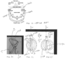
- the subvalvular supporting portion 104 when viewed from the radial direction, could have a profile substantially in the shape of at least one of a rectangle ( Fig. 4 ), an oval ( Fig. 5 ), and a trapezoid ( Fig. 6 ).
- the subvalvular supporting portion 104 when viewed from the radial direction, may have a profile substantially in the shape of a rectangle, but, when viewed from the longitudinal direction, the subvalvular supporting portion 104 may have a profile substantially in the shape of an ellipse.
- the subvalvular supporting portion 104 could be shaped like an elliptical cylinder, for certain use environments of the present invention.
- the subvalvular supporting portion 104 and the anchor portion 106 could have any of a number of different configurations, both absolute and relative. Several of these example configurations are shown in Figs. 7-10 , though these figures, like all figures in the present application, are not drawn to scale. (It should be understood that the anchor portion 106 and the subvalvular supporting portion 104 themselves could have any desired shape or profile, but are shown as being disk -shaped and cylindrical, respectively, for the sake of example.)
- the anchor portion 106 could have a maximum radial dimension (i.e., a maximum measurement in the radial direction R) that is larger than a maximum radial dimension of the subvalvular supporting portion 104. As shown in Fig.
- the anchor portion 106 could have a maximum radial dimension that is the same as a maximum radial dimension of the subvalvular supporting portion 104. As shown in Figs. 8-10 , the anchor portion 106 could have a maximum radial dimension that smaller than a maximum radial dimension of the subvalvular supporting portion 104.
- the subvalvular supporting portion 104, connector neck 108, and anchor portion 106 could also have any desired relative positions in the radial direction.
- the subvalvular supporting portion 104 and the anchor portion 106 can both be substantially circularly symmetrical about the connector neck 108.
- at least one of the subvalvular supporting portion 104 and the anchor portion 106 can be circularly asymmetrical with respect to the connector neck 108. That is, the subvalvular supporting portion 104 and/or the anchor portion 106 could be "offset" in the radial direction from the connector neck 108. This may be desirable for a particular patient's heart structure arrangement.
- the anchor portion 106 In many use environments of the apparatus 100 it will be desirable to have the anchor portion 106 in close proximity to an atrial wall, for example.
- a subvalvular device 102 having a subvalvular supporting portion 104, a connector neck 108, an anchor portion 106 with any desired longitudinal and radial shapes, dimensions, relative arrangements, or other configurations.
- Fig. 11 is a labeled anatomic drawing of a mitral valve portion of a heart, taken from above, and these structures will be referenced herein.
- At least one of the subvalvular supporting portion 104 (shown here) and the anchor portion 106 may be substantially formed of a plurality of longitudinally oriented struts 1228, arranged radially with respect to the longitudinal axis L.
- a body portion of each strut 1228 is selectively bowed radially outward from the longitudinal axis L, during transformation of the subvalvular supporting portion 104 from a transport position (T, in Fig. 14 ) to an operating position (O, in Fig. 14 ).
- the struts 1228 could be subject to a compressive force C in the longitudinal direction.
- both ends of the struts 1228 are anchored, such as via hubs 1230 to a central shaft 1232, the central portions of the struts 1228 will thereby splay outward in a "cocktail umbrella” type manner and can be “locked” there to provide a three-dimensional construct which serves the function of at least one of the subvalvular supporting portion 104 and an anchor portion 106.
- Fig. 14 therefore represents another potential asymmetrical configuration of a subvalvular supporting portion 104, which could be accomplished with the strut 1228 arrangement shown in that figure, or with any other configuration or embodiment of the subvalvular supporting portion 104.
- Fig. 15 schematically illustrates a number of different options, which can be used (singly or in combination) for various use environments of the apparatus 100, as desired.
- the options laid out in Fig. 15 are not exhaustive or exclusive, and an apparatus 100 according to the present invention could include any number, combination, or arrangement of these options.
- the apparatus 100 shown and/or described herein can be introduced and delivered under echocardiographic and/or fluoroscopic guidance through a transcatheter or percutaneous approach with a flexible mechanical adjustment catheter transeptally or transfemorally; by transatrial, transapical, transaortic, transcarotid, and/or transsubclavian artery approaches; by open-heart surgery; by robotically assisted surgery; and/or by minimally invasive surgical procedure through direct visualization.
- Figs. 16-21 show a variety of views of an example apparatus 100 in place within a heart 1634, and particularly in a mitral valve 1636 position of the heart 1634.
- the apparatus 100 of Figs. 16- 21 includes a plurality of subvalvular devices 102.
- both the subvalvular supporting portion 104 and the anchor portion 106 are substantially formed of braided mesh strands.
- one of the subvalvular supporting portion 104 and the anchor portion 106 (here, the subvalvular supporting portion 104) is substantially formed of braided mesh strands and the other of the subvalvular supporting portion 104 and the anchor portion 106 (here, the anchor portion 106) is a balloon.
- the subvalvular supporting portions 104 of both of the subvalvular devices 102 A and 102B of Figs. 16-21 are of the "elliptical cylinder" configuration previously mentioned.
- any number and type(s) of subvalvular devices 102 having any desired physical properties or combinations thereof, could be provided in a single apparatus 100--of any embodiment of the present invention--as desired to reinforce, support, or "bolster" the valve leaflet, and thus achieve desired regurgitation reduction for all the heart valve.
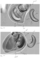
- Figs. 22-31 illustrate a second embodiment of an apparatus 100'.
- the apparatus 100' of Figs. 22-31 is similar to the apparatus 100 of Figs. 1-21 and therefore, structures of Figs. 22-31 that are the same as or similar to those described with reference to Figs. 1-21 have the same reference numbers with the addition of a "prime" mark. Description of common elements and operation similar to those in the previously described first embodiment will not be repeated with respect to the second embodiment.
- Figs. 22-31 illustrate an apparatus 100' which includes at least one subvalvular device 102' having a subvalvular supporting portion 104' with a leaflet-contacting upper supporter surface 210' longitudinally spaced from an oppositely facing lower supporter surface 212'. (In Figs.
- the subvalvular device 102' is shown twice in each picture in substantially the same orientation, once on its own and once in situ in a heart 1634', to better show the shapes and contours being described.)
- At least one of the upper and lower supporter surfaces 210' and 212' includes a convex outer edge 2238 and a concave inner edge 2240, though once again, it is contemplated that these surfaces may not be strictly delineated from one another because of the rounded contours of the subvalvular supporting portion 104' shown and provided for particular use environments.
- a supporter perimeter wall 214' extends longitudinally between, and is integrally and contiguously formed with both of, the upper and lower supporter surfaces 210' and 212'. At least a portion of the supporter perimeter wall 214' contacts a subvalvular cardiac wall 2242 adjacent to the mitral heart valve 1636' concurrently with the concave inner edge 2240 coextending with a posterior leaflet 2244. That is, the concave inner edge 2240 has the same length and contour as a supermajority of, if not substantially an entirety of, the posterior leaflet 2244.
- An anchoring feature (shown schematically at 2246) permanently attaches the subvalvular supporting portion 104' to cardiac tissue such that the subvalvular supporting portion 104' substantially prevents movement of the posterior leaflet 2244 during heart function.
- the anchoring feature 2246 may include at least one of adhesive, tissue ingrowth facilitators, sutures (represented by the "x" marks in Fig. 22 ), staples, and frictional fit (i.e., a dimensional mismatch such that the heart tissue exerts a compressive force sufficient to resist motion of the subvalvular supporting portion 104').
- the anchoring feature 2246 includes an anchor portion 106' and a connector neck 108' similar to those discussed above with respect to the first embodiment of the apparatus 100.
- the anchor portion 106' is a first anchor portion 106'A
- the subvalvular device 102' includes at least one additional anchor portion (here, second anchor portion 106'B) spaced radially from the first anchor portion 106'A.
- both the subvalvular supporting portion 104' and at least one of the anchor portions 106' are balloons, which can be placed and inflated in any desired manner.
- At least a chosen one of the anchor portions 106' may be located at an anterior commissure 2848 of the mitral valve1636 and at least an other one of the anchor portions 106' may be located at a posterior commissure 2850 of the mitral valve 1636.
- the first anchor portion 106'A is located at the posterior commissure 2850 and the second anchor portion 106'B is located at the anterior commissure 2848.
- the subvalvular device 102' of Figs. 20-31 may extend continuously underneath the mitral valve 1636 annulus between the anterior commissure 2848 of the mitral valve 1636 and the posterior commissure 2850 of the mitral valve 1636.
- At least one of the first and second anchor portions 106'A and 106'B may be substantially formed of braided mesh strands. At least one of the first and second anchor portions 106'A and 106'B may be a balloon. One of the first and second anchor portions 106'A and 106'B may be substantially formed of braided mesh strands and the other of the first and second anchor portions 106'A and 106'B may be a balloon.
- At least one of the subvalvular supporting portion 104' and the anchor portion 106' is a balloon, as shown here.
- the subvalvular device 102' shown as an example in Fig. 31 includes a separately provided covering material (shown schematically at 3152 as a mesh material) attached to a majority of an outer surface of the subvalvular device 102'.
- This covering material 3152 could be of any type and could be provided for any desired reason such as, but not limited to, promotion or inhibition of tissue ingrowth and/or prevention of rejection of the apparatus 100' by the body.
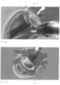
- Figs. 32-35 illustrate a third embodiment of a device 100".
- the device 100" of Figs. 32-35 is similar to the devices 100, 100' of Figs. 1-31 and therefore, structures of Figs. 32-35 that are the same as or similar to those described with reference to Figs. 1- 31 have the same reference numbers with the addition of a double "prime” mark. Description of common elements and operation similar to those in the previously described first and second embodiments will not be repeated with respect to the third embodiment.
- Figs. 32-35 illustrate an apparatus 100" which includes at least one subvalvular device 102" having a subvalvular supporting portion 104" with a leaflet-contacting upper supporter surface 210" longitudinally spaced from an oppositely facing lower supporter surface 212". (In Figs.
- the subvalvular device 102" is shown twice in each picture in substantially the same orientation, once on its own and once in situ in a heart 1634", to better show the shapes and contours being described.)
- At least one of the upper and lower supporter surfaces 210" and 212" includes a convex outer edge 2238" and a concave inner edge 2240", though once again, it is contemplated that these surfaces may not be strictly delineated from one another because of the rounded contours of the subvalvular supporting portion 104" shown and provided for particular use environments.
- each of the upper and lower supporter surfaces 210" and 212" and the supporter perimeter wall 214" are formed from a plurality of radially extending struts 3254 which extend substantially parallel to each other along at least a portion of the length thereof. At least a portion of the supporter perimeter wall 214" contacts a subvalvular cardiac wall 2242" adjacent to the mitral heart valve 1636" concurrently with the concave inner edge 2240" coextending with a posterior leaflet.
- the third embodiment of the apparatus 100" shown in Figs. 32-35 includes a first anchor portion 106"A located at the posterior commissure 2850 and a second anchor portion 106"B is located at the anterior commissure 2848. Accordingly, the subvalvular device 102" of Figs. 32-35 extends continuously underneath the mitral valve 1636" annulus between the anterior commissure 2848" of the mitral valve 1636" and the posterior commissure 2850" of the mitral valve 1636".
- At least one of the first and second anchor portions 106"A and 106"B may be substantially formed of braided mesh strands. At least one of the first and second anchor portions 106"A and 106"B may be a balloon. One of the first and second anchor portions 106"A and 106"B may be substantially formed of braided mesh strands and the other of the first and second anchor portions 106"A and 106"B may be a balloon.
- the subvalvular supporting portion 104" may include a separately provided covering material attached to a majority of an outer surface thereof, for any desired reason.
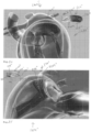
- FIGs. 36-48 a method for at least partially supporting or untethering a leaflet of a regurgitant heart valve using an apparatus 100 according to any aspect or embodiment of the present invention will be described.
- One subvalvular device 102 of the type shown in Figs. 16-21 , is shown in Figs. 36-48 for the sake of discussion. However, it is contemplated that any number or type of subvalvular devices 102 could be used in apparatus 100 via the method described below, such as, but not limited to, any one or more of the structures shown and described in Figs. 1-35 .
- FIG. 36-37 An example flowchart of a method incorporating the below description is shown in Figs. 36-37 , where the circled "1" represents a continuation of the flowchart from Fig. 36 to Fig. 37 .
- the flowchart of Figs. 36-37 illustrates one potential approach (a transfemoral approach) for providing a patient with an apparatus 100 according to the present invention.
- Figs. 38-48 depict another, potentially related, example approach.
- One of ordinary skill in the art will be able to provide a suitable surgical approach and corresponding apparatus 100, configured as desired, for a particular use environment without harm to the present invention.
- a variable-dimension sizer 4164 may be placed adjacent the manufactured puncture site 4060 at a location on a lower side of the leaflet 2244.
- the sizer 4164 could be, for example, a balloon, as shown, with a shape mimicking that of the subvalvular supporting portion 104 of a corresponding subvalvular device 102 to be implanted in the heart 1634.
- At least one dimension of the sizer 4164 could be varied, as shown in Fig. 39 , to ascertain the presence of a predetermined effect upon the leaflet 2240 responsive to the at least one sizer 4164 dimension.
- the sizer 4164 could be deflated and retracted from the heart 1634.
- the sizer 4164 can be delivered in a retrograde fashion through a transfemoral, transbrachial, or transradial access, or in any other desired manner, for both subvalvular mitral spacer device implantation approaches.
- the sizer 4164 can go through a beating aortic valve and flex toward the ventricular side of mitral valve 1636 annulus, for placement under the mitral valve leaflet 2244 in the ventricular subvalvular space location surrounding by the left ventricular posterior wall.
- the physician can navigate the sizer 4164 inside the subvalvular space by fluoroscopy and/or TEE guidance, such as via a catheter 3858, until the sizer 4164 reaches the desired location (e.g., P1, P2, and/or P3 leaflet scallop levels) and is oriented at a desired vector pointing the sizer 4164 from the ventricle toward the atrium.
- the sizer 4164 may be inflated in the preselected anatomical position.
- any desired imaging means such as, but not limited to, 2D or 3D real time echocardiograph, the physician can assess the reduction or elimination of mitral valve regurgitation by pushing or moving forward the tethering posterior leaflet 2244 by the sizer 4164 expansion.
- This "test" sizer 4164 inflation can help to show the surface of leaflet 2244 coaptation between the posterior 2244 and the anterior leaflets before the implantation of an at least semi-permanent subvalvular device 102.
- the size of the sizer 4164 inflation also can be measured by increasing the saline solution volume from small, to medium, to large or even extra-large size, as desired.
- the operator can assess and calibrate the final subvalvular device 102 size appropriate to achieve the desirable competent mitral valve 1636 function, as well as the proper positioning for that subvalvular device 102, through the use of the sizer 4164.
- a guidewire 3856 may be placed into the patient's heart 1634, at any desired time during the procedure, where it will remain throughout the majority of the method described herein.
- the guidewire 3856 is shown as being placed and used as in the sequence of Figs. 41-43 , after the sizer 4164 has been employed. However, it is contemplated that the guidewire 3856 could also or instead be used in conjunction with the sizer 4164, as desired.
- the guidewire may be placed in any suitable manner, such as, but not limited to minimally invasive surgical techniques.
- a catheter 3858 may be guided into the patient's heart 1634 via the guidewire 3856.
- the catheter 3858 can then be used to introduce various structures into the heart 1634, for temporary or permanent location they are in conjunction with installation of the apparatus 100.
- the guidewire 3856 and/or a subvalvular device 102 could be advanced through a catheter 3858 and into the heart 1634.
- the guidewire 3856 may be advanced longitudinally through the valve-adjacent heart tissue, shown and described herein as being at least one of a base of a posterior leaflet 2244 and an annulus of the mitral valve 1636.
- the apparatus 100 could be installed, using a similar technique, in relationship with a tricuspid and/or aortic valve of a heart 1634.
- the guidewire 3856 and/or any other desired surgical tool may penetrate completely through at least one of a base of a posterior leaflet 2244 and an annulus of the mitral valve 1636 to create a manufactured puncture site 4060.
- the guidewire 3856 could be fed through the heart tissue itself, or another surgical tool could be used to help pierce the heart tissue.
- the manufactured puncture site 4060 could be created by mechanically cutting through the heart tissue with a physically sharp puncture device 4062, like the depicted needle, and/or by electrosurgically cutting through the heart tissue with an electrically-powered cutting device, such as a Bovie knife or cauterizing probe, or application of local RF energy.
- an electrically-powered cutting device such as a Bovie knife or cauterizing probe, or application of local RF energy.
- a subvalvular device 102 is provided, such as any of those depicted and described herein, or any other subvalvular devices 102 configured by one of ordinary skill in the art with reference to the teachings of the present application.
- a particular subvalvular device 102 for implantation could be selected from a plurality of provided subvalvular devices responsive to the varying of the at least one dimension of the sizer 4164.
- a "medium” sized subvalvular device 102 could be selected for use with that patient.
- the subvalvular device 102 can be advanced into the heart 1634.
- the anchor portion 106 can be advanced through the manufactured puncture site 4060 to a predetermined anchor location on an upper side of at least one of a base of a posterior leaflet 2244 and an annulus of the mitral valve 1636.
- the anchor portion 106 can then be deployed at the predetermined anchor location, as shown in Fig. 44 .
- the subvalvular device 102 is maintained with the connector neck 108 penetrating longitudinally through at least one of a base of a posterior leaflet 2244 and an annulus of the mitral valve 1636 at the manufactured puncture site 4060. Then, as shown in Figs. 45-48 , the subvalvular supporting portion 104 is deployed longitudinally adjacent the manufactured puncture site 4060 at a location on a lower side of the leaflet 2244, with at least a portion of the supporter perimeter wall 214 contacting a subvalvular cardiac wall 2242 adjacent to the valve 1636.
- At least one of a base of a posterior leaflet 2244 and an annulus of the mitral valve 1636 is interposed longitudinally between the anchor portion 106 and the subvalvular supporting portion 104 to locate the subvalvular device 102 in an operating position with respect to the valve 1636, as shown in Figs. 46-48 .
- deployment of the anchor portion 106 and/or the subvalvular supporting portion 104 can occur in any suitable manner, and will depend upon the nature of those components.
- deployment may include expanding the braided mesh strand construct comprising at least a portion of the anchor portion 106 and/or the subvalvular supporting portion 104.
- deployment of the anchor portion 106 and/or the subvalvular supporting portion 104 may include inflating a balloon comprising at least a portion of the anchor portion 106 and/or the subvalvular supporting portion 104; or bowing radially outward from each other a body portion of each strut of a plurality of longitudinally oriented struts comprising at least a portion of the anchor portion 106 and/or the subvalvular supporting portion 104.
- the anchor portion 106 and/or the subvalvular supporting portion 104 are deployed, though, once the subvalvular device 102 is in place in the operating position, movement of the leaflet 2244 is resisted during heart operation to substantially support the leaflet.
- mechanical function of the valve 1636 could be tested with the subvalvular device 102 maintained in the operating position. At least one of a position of the subvalvular device 102 and at least one dimension of the subvalvular device 102 could be adjusted, such as by deploying the subvalvular device, or components thereof, more fully responsive to results of the mechanical function testing. As a result, the user can "fine tune" the apparatus 100 to achieve desired results upon the regurgitation characteristics of the valve 1636.
- the guidewire 3856 may be removed from the heart 1634 of the patient at any desired time during the surgical procedure, though it is contemplated that the guidewire 3856 will be removed (optionally including releasing at least a portion of the apparatus 100 therefrom) at the final conclusion of the surgical procedure, in most cases.
- the surgical incision can then be closed and the surgical procedure concluded in a known manner. While the method shown in Figs.
- Any component could be provided with a user-perceptible marking to indicate a material, configuration, at least one dimension, or the like pertaining to that component, the user-perceptible marking potentially aiding a user in selecting one component from an array of similar components for a particular use environment.
- a "predetermined" status may be determined at any time before the structures being manipulated actually reach that status, the “predetermination” being made as late as immediately before the structure achieves the predetermined status.
- the term “substantially” is used herein to indicate a quality that is largely, but not necessarily wholly, that which is specified--a "substantial” quality admits of the potential for some relatively minor inclusion of a non-quality item.
Claims (10)
- Appareil de support au moins partiel d'un feuillet d'une valvule cardiaque à régurgitation, l'appareil comprenant au moins un dispositif sous-valvulaire (102) définissant un axe longitudinal et comportant :une partie de support sous-valvulaire (104) comportant une surface de support supérieure (210) en contact avec le feuillet, espacée longitudinalement d'une surface de support inférieure (212) faisant face de manière opposée, une paroi périmétrique de support (214) s'étendant longitudinalement entre les deux des surfaces de support supérieure et inférieure (210, 212), et formée d'un seul tenant et de manière contiguë avec elles, au moins une partie de la paroi périmétrique de support (214) étant configurée pour entrer en contact avec une paroi cardiaque sous-valvulaire adjacente à la valvule cardiaque ;une partie d'ancrage (106) adjacente à la surface de support supérieure (210) et espacée longitudinalement de celle-ci, la partie d'ancrage (106) comportant une surface d'ancrage inférieure (218) en contact avec le feuillet espacée longitudinalement d'une surface d'ancrage supérieure (216) faisant face de manière opposée, une paroi périmétrique d'ancrage (220) s'étendant longitudinalement entre les deux des surfaces d'ancrage supérieure et inférieure (218 et 216) et formée d'un seul tenant et de manière contiguë avec elles ; etun col de connecteur (108) interposé longitudinalement entre, et directement fixé aux deux de la surface de support supérieure (210) et de la surface d'ancrage inférieure (218), le col de connecteur (108) étant conçu pour pénétrer longitudinalement à travers au moins l'un d'une base du feuillet et d'un anneau de la valvule cardiaque au niveau d'un site de ponction fabriqué ;dans lequel la partie de support sous-valvulaire (104), la partie d'ancrage (106) et le col de connecteur (108) enferment collectivement un seul volume intérieur contigu.
- Appareil selon la revendication 1, dans lequel les deux des surfaces de support supérieure et inférieure (210, 212) sont sensiblement planes et mutuellement parallèles.
- Appareil selon la revendication 1, dans lequel les deux des surfaces de support supérieure et inférieure (210, 212) comportent un contour variable longitudinalement le long d'une dimension radiale de celles-ci, les contours des surfaces de support supérieure et inférieure (210, 212) étant sensiblement reflétés l'un par rapport à l'autre autour d'un plan orienté radialement, et les surfaces de support supérieure et inférieure (210, 212) et la paroi périphérique de support (214) définissent collectivement une partie de support sous-valvulaire sensiblement torique (102).
- Appareil selon la revendication 1, dans lequel la partie d'ancrage (106) a une dimension radiale maximale plus petite qu'une dimension radiale maximale de la partie de support sous-valvulaire (104).
- Appareil selon la revendication 1, dans lequel la partie de support sous-valvulaire (104) et la partie d'ancrage (106) sont toutes deux symétriques de révolution autour du col du connecteur.
- Appareil selon la revendication 1, dans lequel le dispositif sous-valvulaire (102) comporte au moins un d'un capuchon supérieur (124) et d'un capuchon inférieur (326), les capuchons supérieur et inférieur (124 et 326) dépassant du col du connecteur (108) dans la direction longitudinale à partir de la surface d'ancrage supérieure (216) et de la surface de support inférieure (212), respectivement.
- Appareil selon la revendication 1, dans lequel la partie de support sous-valvulaire (104) et la partie d'ancrage (106) sont sensiblement formées de brins de maille tressés.
- Appareil selon la revendication 1, dans lequel la partie de support sous-valvulaire (104) et la partie d'ancrage (106) sont des ballons.
- Appareil selon la revendication 1, dans lequel l'une de la partie de support sous-valvulaire (104) et de la partie d'ancrage (106) est sensiblement formée de brins de maille tressés et l'autre de la partie de support sous-valvulaire (104) et la partie d'ancrage (106) est un ballon.
- Appareil selon la revendication 1, dans lequel au moins l'une de la partie de support sous-valvulaire (104) et de la partie d'ancrage (106) est sensiblement formée d'une pluralité d'entretoises (1228) orientées longitudinalement, disposées radialement par rapport à l'axe longitudinal, une partie de corps de chaque entretoise (1228) étant sélectivement courbée radialement vers l'extérieur à partir de l'axe longitudinal.
Applications Claiming Priority (2)
| Application Number | Priority Date | Filing Date | Title |
|---|---|---|---|
| US201662375146P | 2016-08-15 | 2016-08-15 | |
| PCT/US2017/046912 WO2018035105A1 (fr) | 2016-08-15 | 2017-08-15 | Appareils et procédés de support au moins partiel de feuillet de valvule d'une valvule cardiaque à régurgitation |
Publications (2)
| Publication Number | Publication Date |
|---|---|
| EP3496665A1 EP3496665A1 (fr) | 2019-06-19 |
| EP3496665B1 true EP3496665B1 (fr) | 2023-11-15 |
Family
ID=59846631
Family Applications (1)
| Application Number | Title | Priority Date | Filing Date |
|---|---|---|---|
| EP17764930.8A Active EP3496665B1 (fr) | 2016-08-15 | 2017-08-15 | Appareils de support au moins partiel de feuillet de valvule d'une valvule cardiaque à régurgitation |
Country Status (4)
| Country | Link |
|---|---|
| US (2) | US10537432B2 (fr) |
| EP (1) | EP3496665B1 (fr) |
| JP (1) | JP7199344B2 (fr) |
| WO (1) | WO2018035105A1 (fr) |
Families Citing this family (21)
| Publication number | Priority date | Publication date | Assignee | Title |
|---|---|---|---|---|
| US20220031456A1 (en) * | 2016-08-15 | 2022-02-03 | The Cleveland Clinic Foundation | Apparatuses and methods for at least partially supporting a valve leaflet of a regurgitant heart valve |
| US11083581B2 (en) | 2017-12-04 | 2021-08-10 | Edwards Lifesciences Corporation | Expandable heart valve coaptation device |
| WO2019195860A2 (fr) | 2018-04-04 | 2019-10-10 | Vdyne, Llc | Dispositifs et procédés d'ancrage d'une valvule cardiaque transcathéter |
| US11071627B2 (en) | 2018-10-18 | 2021-07-27 | Vdyne, Inc. | Orthogonally delivered transcatheter heart valve frame for valve in valve prosthesis |
| US11344413B2 (en) | 2018-09-20 | 2022-05-31 | Vdyne, Inc. | Transcatheter deliverable prosthetic heart valves and methods of delivery |
| US10321995B1 (en) | 2018-09-20 | 2019-06-18 | Vdyne, Llc | Orthogonally delivered transcatheter heart valve replacement |
| US11278437B2 (en) | 2018-12-08 | 2022-03-22 | Vdyne, Inc. | Compression capable annular frames for side delivery of transcatheter heart valve replacement |
| US10595994B1 (en) | 2018-09-20 | 2020-03-24 | Vdyne, Llc | Side-delivered transcatheter heart valve replacement |
| US11109969B2 (en) | 2018-10-22 | 2021-09-07 | Vdyne, Inc. | Guidewire delivery of transcatheter heart valve |
| US11253359B2 (en) | 2018-12-20 | 2022-02-22 | Vdyne, Inc. | Proximal tab for side-delivered transcatheter heart valves and methods of delivery |
| US11273032B2 (en) | 2019-01-26 | 2022-03-15 | Vdyne, Inc. | Collapsible inner flow control component for side-deliverable transcatheter heart valve prosthesis |
| US11185409B2 (en) | 2019-01-26 | 2021-11-30 | Vdyne, Inc. | Collapsible inner flow control component for side-delivered transcatheter heart valve prosthesis |
| WO2020181154A2 (fr) | 2019-03-05 | 2020-09-10 | Vdyne, Inc. | Dispositifs de régulation de régurgitation tricuspide pour prothèse de valvule cardiaque transcathéter orthogonale |
| US11173027B2 (en) | 2019-03-14 | 2021-11-16 | Vdyne, Inc. | Side-deliverable transcatheter prosthetic valves and methods for delivering and anchoring the same |
| US11076956B2 (en) | 2019-03-14 | 2021-08-03 | Vdyne, Inc. | Proximal, distal, and anterior anchoring tabs for side-delivered transcatheter mitral valve prosthesis |
| JP2022530764A (ja) | 2019-05-04 | 2022-07-01 | ブイダイン,インコーポレイテッド | 生来の弁輪での側方送達される人工心臓弁を展開するための締め付けデバイス及び方法 |
| EP4017442A4 (fr) | 2019-08-20 | 2023-07-26 | Vdyne, Inc. | Dispositifs d'administration et de récupération et procédés pour valvules prothétiques transcathéter à pose latérale |
| CN114630665A (zh) | 2019-08-26 | 2022-06-14 | 维迪内股份有限公司 | 可侧面输送的经导管假体瓣膜及其输送和锚定方法 |
| US11234813B2 (en) | 2020-01-17 | 2022-02-01 | Vdyne, Inc. | Ventricular stability elements for side-deliverable prosthetic heart valves and methods of delivery |
| WO2022035728A1 (fr) * | 2020-08-12 | 2022-02-17 | The Cleveland Clinic Foundation | Appareils et procédés de support au moins partiel de feuillet de valvule d'une valvule cardiaque à régurgitation |
| WO2023141132A1 (fr) | 2022-01-18 | 2023-07-27 | The Cleveland Clinic Foundation | Appareils permettant de réparer, au moins partiellement, une valvule cardiaque à régurgitation |
Citations (2)
| Publication number | Priority date | Publication date | Assignee | Title |
|---|---|---|---|---|
| EP2591755A1 (fr) * | 2011-11-12 | 2013-05-15 | Medtentia International Ltd Oy | Dispositif et procédé d'amélioration de la fixation d'un dispositif médical |
| US20160030176A1 (en) * | 2014-08-04 | 2016-02-04 | Medizinische Universität Wien | Implant and method for improving coaptation of an atrioventricular valve |
Family Cites Families (36)
| Publication number | Priority date | Publication date | Assignee | Title |
|---|---|---|---|---|
| US5725552A (en) | 1994-07-08 | 1998-03-10 | Aga Medical Corporation | Percutaneous catheter directed intravascular occlusion devices |
| US6123715A (en) | 1994-07-08 | 2000-09-26 | Amplatz; Curtis | Method of forming medical devices; intravascular occlusion devices |
| US5846261A (en) | 1994-07-08 | 1998-12-08 | Aga Medical Corp. | Percutaneous catheter directed occlusion devices |
| US5944738A (en) | 1998-02-06 | 1999-08-31 | Aga Medical Corporation | Percutaneous catheter directed constricting occlusion device |
| ATE484241T1 (de) | 1999-04-09 | 2010-10-15 | Evalve Inc | Verfahren und vorrichtung zur herzklappenreperation |
| US6454799B1 (en) * | 2000-04-06 | 2002-09-24 | Edwards Lifesciences Corporation | Minimally-invasive heart valves and methods of use |
| US20020107531A1 (en) * | 2001-02-06 | 2002-08-08 | Schreck Stefan G. | Method and system for tissue repair using dual catheters |
| US8641727B2 (en) | 2002-06-13 | 2014-02-04 | Guided Delivery Systems, Inc. | Devices and methods for heart valve repair |
| US20070255396A1 (en) | 2003-06-20 | 2007-11-01 | Medtronic Vascular, Inc. | Chrodae Tendinae Girdle |
| US20060015178A1 (en) | 2004-07-15 | 2006-01-19 | Shahram Moaddeb | Implants and methods for reshaping heart valves |
| WO2006041877A2 (fr) | 2004-10-05 | 2006-04-20 | Ample Medical, Inc. | Systemes et procedes de reparation d'un anneau de valvule auriculo-ventriculaire faisant appel a des ancrages retro-chordaux |
| CA2597066C (fr) | 2005-02-07 | 2014-04-15 | Evalve, Inc. | Procedes, systemes et dispositifs pour reparer une valvule cardiaque |
| WO2006097931A2 (fr) | 2005-03-17 | 2006-09-21 | Valtech Cardio, Ltd. | Techniques de traitement de la valve mitrale |
| US7785366B2 (en) | 2005-10-26 | 2010-08-31 | Maurer Christopher W | Mitral spacer |
| US20070100439A1 (en) | 2005-10-31 | 2007-05-03 | Medtronic Vascular, Inc. | Chordae tendinae restraining ring |
| US7635386B1 (en) | 2006-03-07 | 2009-12-22 | University Of Maryland, Baltimore | Methods and devices for performing cardiac valve repair |
| DE102006013770A1 (de) * | 2006-03-24 | 2007-09-27 | Occlutech Gmbh | Occlusionsinstrument und Verfahren zu dessen Herstellung |
| US20080039935A1 (en) | 2006-08-14 | 2008-02-14 | Wally Buch | Methods and apparatus for mitral valve repair |
| US20100137999A1 (en) | 2007-03-15 | 2010-06-03 | Bioprotect Led. | Soft tissue fixation devices |
| WO2008149355A2 (fr) | 2007-06-04 | 2008-12-11 | Mor Research Applications Ltd. | Augmentation de feuillet de valvule cardiaque |
| US8430927B2 (en) * | 2008-04-08 | 2013-04-30 | Medtronic, Inc. | Multiple orifice implantable heart valve and methods of implantation |
| CA3035048C (fr) | 2010-12-23 | 2021-05-04 | Mark Deem | Systeme de reparation et remplacement de valvule mitrale |
| WO2012127309A1 (fr) * | 2011-03-21 | 2012-09-27 | Ontorfano Matteo | Appareil pour valvule à disques et procédé de traitement du dysfonctionnement de la valvule |
| US8562643B2 (en) | 2011-04-21 | 2013-10-22 | Cook Medical Technologies Llc | Self closing occulsion device with a twist |
| WO2013003228A1 (fr) | 2011-06-27 | 2013-01-03 | University Of Maryland, Baltimore | Dispositif de réparation par voie apicale de valvule mitrale |
| US9011515B2 (en) * | 2012-04-19 | 2015-04-21 | Caisson Interventional, LLC | Heart valve assembly systems and methods |
| CN108294846A (zh) | 2013-05-20 | 2018-07-20 | 托尔福公司 | 可植入心脏瓣膜装置、二尖瓣修复装置以及相关系统和方法 |
| EP3030161A4 (fr) * | 2013-08-06 | 2017-03-22 | LC Therapeutics, Inc. | Cordon synthétique pour applications de réparation de valvules cardiaques |
| US9393111B2 (en) * | 2014-01-15 | 2016-07-19 | Sino Medical Sciences Technology Inc. | Device and method for mitral valve regurgitation treatment |
| US9839511B2 (en) * | 2013-10-05 | 2017-12-12 | Sino Medical Sciences Technology Inc. | Device and method for mitral valve regurgitation treatment |
| US9050188B2 (en) * | 2013-10-23 | 2015-06-09 | Caisson Interventional, LLC | Methods and systems for heart valve therapy |
| US10166098B2 (en) * | 2013-10-25 | 2019-01-01 | Middle Peak Medical, Inc. | Systems and methods for transcatheter treatment of valve regurgitation |
| US9532870B2 (en) * | 2014-06-06 | 2017-01-03 | Edwards Lifesciences Corporation | Prosthetic valve for replacing a mitral valve |
| US10080660B2 (en) | 2014-12-19 | 2018-09-25 | Paradox Medical Limited | Implantable intracardiac device and methods thereof |
| ES2906137T3 (es) * | 2017-04-18 | 2022-04-13 | Edwards Lifesciences Corp | Dispositivos de sellado de válvula cardíaca y dispositivos de suministro para los mismos |
| US11065117B2 (en) * | 2017-09-08 | 2021-07-20 | Edwards Lifesciences Corporation | Axisymmetric adjustable device for treating mitral regurgitation |
-
2017
- 2017-08-15 EP EP17764930.8A patent/EP3496665B1/fr active Active
- 2017-08-15 JP JP2019508209A patent/JP7199344B2/ja active Active
- 2017-08-15 WO PCT/US2017/046912 patent/WO2018035105A1/fr unknown
- 2017-08-15 US US15/677,470 patent/US10537432B2/en active Active
-
2019
- 2019-12-12 US US16/712,059 patent/US11241313B2/en active Active
Patent Citations (2)
| Publication number | Priority date | Publication date | Assignee | Title |
|---|---|---|---|---|
| EP2591755A1 (fr) * | 2011-11-12 | 2013-05-15 | Medtentia International Ltd Oy | Dispositif et procédé d'amélioration de la fixation d'un dispositif médical |
| US20160030176A1 (en) * | 2014-08-04 | 2016-02-04 | Medizinische Universität Wien | Implant and method for improving coaptation of an atrioventricular valve |
Also Published As
| Publication number | Publication date |
|---|---|
| US20200113687A1 (en) | 2020-04-16 |
| US11241313B2 (en) | 2022-02-08 |
| US20180071093A1 (en) | 2018-03-15 |
| JP2019524335A (ja) | 2019-09-05 |
| EP3496665A1 (fr) | 2019-06-19 |
| JP7199344B2 (ja) | 2023-01-05 |
| US10537432B2 (en) | 2020-01-21 |
| WO2018035105A1 (fr) | 2018-02-22 |
Similar Documents
| Publication | Publication Date | Title |
|---|---|---|
| US11241313B2 (en) | Apparatuses and methods for at least partially supporting a valve leaflet of a regurgitant heart valve | |
| US11925553B2 (en) | Valve docking devices, systems and methods | |
| US20220257377A1 (en) | Heart valve anchoring device | |
| US20210030538A1 (en) | Methods of implantation of transcatheter atrial sealing skirt, anchor, and tether | |
| CA3004418C (fr) | Dispositif, systeme et procede pour le traitement, par transcatheter, d'une regurgitation valvulaire | |
| US10213304B2 (en) | Apparatus, system, and method for treating a regurgitant heart valve | |
| EP3017792B1 (fr) | Systèmes de thérapie de valvule cardiaque | |
| AU2021282497A1 (en) | Systems and methods for heart valve leaflet repair | |
| US20120035703A1 (en) | Truncated Conical Heart Valve Stent with Anchoring Threads and Methods of Use | |
| EP3269328A2 (fr) | Implant de valvule cardiaque | |
| EP3154476A1 (fr) | Ensemble valve mitrale à ancre à implanter en deux étapes | |
| CN113164253A (zh) | 用于二尖瓣的经导管锚固组件、二尖瓣和相关方法 | |
| CN107920862B (zh) | 用于心脏瓣膜疗法的系统和方法 | |
| US20220031456A1 (en) | Apparatuses and methods for at least partially supporting a valve leaflet of a regurgitant heart valve | |
| US20200188109A1 (en) | Coaptation zone curtain | |
| WO2022035728A1 (fr) | Appareils et procédés de support au moins partiel de feuillet de valvule d'une valvule cardiaque à régurgitation | |
| CN117015357A (zh) | 瓣环成形术装置 |
Legal Events
| Date | Code | Title | Description |
|---|---|---|---|
| STAA | Information on the status of an ep patent application or granted ep patent |
Free format text: STATUS: UNKNOWN |
|
| STAA | Information on the status of an ep patent application or granted ep patent |
Free format text: STATUS: THE INTERNATIONAL PUBLICATION HAS BEEN MADE |
|
| PUAI | Public reference made under article 153(3) epc to a published international application that has entered the european phase |
Free format text: ORIGINAL CODE: 0009012 |
|
| STAA | Information on the status of an ep patent application or granted ep patent |
Free format text: STATUS: REQUEST FOR EXAMINATION WAS MADE |
|
| 17P | Request for examination filed |
Effective date: 20190228 |
|
| AK | Designated contracting states |
Kind code of ref document: A1 Designated state(s): AL AT BE BG CH CY CZ DE DK EE ES FI FR GB GR HR HU IE IS IT LI LT LU LV MC MK MT NL NO PL PT RO RS SE SI SK SM TR |
|
| AX | Request for extension of the european patent |
Extension state: BA ME |
|
| DAV | Request for validation of the european patent (deleted) | ||
| DAX | Request for extension of the european patent (deleted) | ||
| STAA | Information on the status of an ep patent application or granted ep patent |
Free format text: STATUS: EXAMINATION IS IN PROGRESS |
|
| 17Q | First examination report despatched |
Effective date: 20200917 |
|
| STAA | Information on the status of an ep patent application or granted ep patent |
Free format text: STATUS: EXAMINATION IS IN PROGRESS |
|
| GRAP | Despatch of communication of intention to grant a patent |
Free format text: ORIGINAL CODE: EPIDOSNIGR1 |
|
| STAA | Information on the status of an ep patent application or granted ep patent |
Free format text: STATUS: GRANT OF PATENT IS INTENDED |
|
| INTG | Intention to grant announced |
Effective date: 20230609 |
|
| GRAS | Grant fee paid |
Free format text: ORIGINAL CODE: EPIDOSNIGR3 |
|
| GRAA | (expected) grant |
Free format text: ORIGINAL CODE: 0009210 |
|
| STAA | Information on the status of an ep patent application or granted ep patent |
Free format text: STATUS: THE PATENT HAS BEEN GRANTED |
|
| P01 | Opt-out of the competence of the unified patent court (upc) registered |
Effective date: 20230928 |
|
| AK | Designated contracting states |
Kind code of ref document: B1 Designated state(s): AL AT BE BG CH CY CZ DE DK EE ES FI FR GB GR HR HU IE IS IT LI LT LU LV MC MK MT NL NO PL PT RO RS SE SI SK SM TR |
|
| REG | Reference to a national code |
Ref country code: CH Ref legal event code: EP Ref country code: GB Ref legal event code: FG4D |
|
| REG | Reference to a national code |
Ref country code: DE Ref legal event code: R096 Ref document number: 602017076528 Country of ref document: DE |
|
| REG | Reference to a national code |
Ref country code: IE Ref legal event code: FG4D |
|
| REG | Reference to a national code |
Ref country code: LT Ref legal event code: MG9D |
|
| REG | Reference to a national code |
Ref country code: NL Ref legal event code: MP Effective date: 20231115 |
|
| PG25 | Lapsed in a contracting state [announced via postgrant information from national office to epo] |
Ref country code: GR Free format text: LAPSE BECAUSE OF FAILURE TO SUBMIT A TRANSLATION OF THE DESCRIPTION OR TO PAY THE FEE WITHIN THE PRESCRIBED TIME-LIMIT Effective date: 20240216 |
|
| PG25 | Lapsed in a contracting state [announced via postgrant information from national office to epo] |
Ref country code: IS Free format text: LAPSE BECAUSE OF FAILURE TO SUBMIT A TRANSLATION OF THE DESCRIPTION OR TO PAY THE FEE WITHIN THE PRESCRIBED TIME-LIMIT Effective date: 20240315 |
|
| PG25 | Lapsed in a contracting state [announced via postgrant information from national office to epo] |
Ref country code: LT Free format text: LAPSE BECAUSE OF FAILURE TO SUBMIT A TRANSLATION OF THE DESCRIPTION OR TO PAY THE FEE WITHIN THE PRESCRIBED TIME-LIMIT Effective date: 20231115 |
|
| REG | Reference to a national code |
Ref country code: AT Ref legal event code: MK05 Ref document number: 1631078 Country of ref document: AT Kind code of ref document: T Effective date: 20231115 |
|
| PG25 | Lapsed in a contracting state [announced via postgrant information from national office to epo] |
Ref country code: NL Free format text: LAPSE BECAUSE OF FAILURE TO SUBMIT A TRANSLATION OF THE DESCRIPTION OR TO PAY THE FEE WITHIN THE PRESCRIBED TIME-LIMIT Effective date: 20231115 |
|
| PG25 | Lapsed in a contracting state [announced via postgrant information from national office to epo] |
Ref country code: AT Free format text: LAPSE BECAUSE OF FAILURE TO SUBMIT A TRANSLATION OF THE DESCRIPTION OR TO PAY THE FEE WITHIN THE PRESCRIBED TIME-LIMIT Effective date: 20231115 |