EP3496257A1 - Three-level circuit and control method for balancing neutral point voltage of the same - Google Patents
Three-level circuit and control method for balancing neutral point voltage of the same Download PDFInfo
- Publication number
- EP3496257A1 EP3496257A1 EP18207313.0A EP18207313A EP3496257A1 EP 3496257 A1 EP3496257 A1 EP 3496257A1 EP 18207313 A EP18207313 A EP 18207313A EP 3496257 A1 EP3496257 A1 EP 3496257A1
- Authority
- EP
- European Patent Office
- Prior art keywords
- level
- bridge arm
- phase
- voltage
- neutral point
- Prior art date
- Legal status (The legal status is an assumption and is not a legal conclusion. Google has not performed a legal analysis and makes no representation as to the accuracy of the status listed.)
- Granted
Links
Images


Classifications
-
- H—ELECTRICITY
- H02—GENERATION; CONVERSION OR DISTRIBUTION OF ELECTRIC POWER
- H02M—APPARATUS FOR CONVERSION BETWEEN AC AND AC, BETWEEN AC AND DC, OR BETWEEN DC AND DC, AND FOR USE WITH MAINS OR SIMILAR POWER SUPPLY SYSTEMS; CONVERSION OF DC OR AC INPUT POWER INTO SURGE OUTPUT POWER; CONTROL OR REGULATION THEREOF
- H02M7/00—Conversion of AC power input into DC power output; Conversion of DC power input into AC power output
- H02M7/42—Conversion of DC power input into AC power output without possibility of reversal
- H02M7/44—Conversion of DC power input into AC power output without possibility of reversal by static converters
- H02M7/48—Conversion of DC power input into AC power output without possibility of reversal by static converters using discharge tubes with control electrode or semiconductor devices with control electrode
- H02M7/483—Converters with outputs that each can have more than two voltages levels
- H02M7/487—Neutral point clamped inverters
-
- H—ELECTRICITY
- H02—GENERATION; CONVERSION OR DISTRIBUTION OF ELECTRIC POWER
- H02M—APPARATUS FOR CONVERSION BETWEEN AC AND AC, BETWEEN AC AND DC, OR BETWEEN DC AND DC, AND FOR USE WITH MAINS OR SIMILAR POWER SUPPLY SYSTEMS; CONVERSION OF DC OR AC INPUT POWER INTO SURGE OUTPUT POWER; CONTROL OR REGULATION THEREOF
- H02M7/00—Conversion of AC power input into DC power output; Conversion of DC power input into AC power output
- H02M7/42—Conversion of DC power input into AC power output without possibility of reversal
- H02M7/44—Conversion of DC power input into AC power output without possibility of reversal by static converters
- H02M7/48—Conversion of DC power input into AC power output without possibility of reversal by static converters using discharge tubes with control electrode or semiconductor devices with control electrode
- H02M7/483—Converters with outputs that each can have more than two voltages levels
- H02M7/4833—Capacitor voltage balancing
-
- H—ELECTRICITY
- H02—GENERATION; CONVERSION OR DISTRIBUTION OF ELECTRIC POWER
- H02M—APPARATUS FOR CONVERSION BETWEEN AC AND AC, BETWEEN AC AND DC, OR BETWEEN DC AND DC, AND FOR USE WITH MAINS OR SIMILAR POWER SUPPLY SYSTEMS; CONVERSION OF DC OR AC INPUT POWER INTO SURGE OUTPUT POWER; CONTROL OR REGULATION THEREOF
- H02M7/00—Conversion of AC power input into DC power output; Conversion of DC power input into AC power output
- H02M7/42—Conversion of DC power input into AC power output without possibility of reversal
- H02M7/44—Conversion of DC power input into AC power output without possibility of reversal by static converters
- H02M7/48—Conversion of DC power input into AC power output without possibility of reversal by static converters using discharge tubes with control electrode or semiconductor devices with control electrode
- H02M7/53—Conversion of DC power input into AC power output without possibility of reversal by static converters using discharge tubes with control electrode or semiconductor devices with control electrode using devices of a triode or transistor type requiring continuous application of a control signal
- H02M7/537—Conversion of DC power input into AC power output without possibility of reversal by static converters using discharge tubes with control electrode or semiconductor devices with control electrode using devices of a triode or transistor type requiring continuous application of a control signal using semiconductor devices only, e.g. single switched pulse inverters
- H02M7/5387—Conversion of DC power input into AC power output without possibility of reversal by static converters using discharge tubes with control electrode or semiconductor devices with control electrode using devices of a triode or transistor type requiring continuous application of a control signal using semiconductor devices only, e.g. single switched pulse inverters in a bridge configuration
- H02M7/53871—Conversion of DC power input into AC power output without possibility of reversal by static converters using discharge tubes with control electrode or semiconductor devices with control electrode using devices of a triode or transistor type requiring continuous application of a control signal using semiconductor devices only, e.g. single switched pulse inverters in a bridge configuration with automatic control of output voltage or current
- H02M7/53873—Conversion of DC power input into AC power output without possibility of reversal by static converters using discharge tubes with control electrode or semiconductor devices with control electrode using devices of a triode or transistor type requiring continuous application of a control signal using semiconductor devices only, e.g. single switched pulse inverters in a bridge configuration with automatic control of output voltage or current with digital control
-
- H—ELECTRICITY
- H02—GENERATION; CONVERSION OR DISTRIBUTION OF ELECTRIC POWER
- H02M—APPARATUS FOR CONVERSION BETWEEN AC AND AC, BETWEEN AC AND DC, OR BETWEEN DC AND DC, AND FOR USE WITH MAINS OR SIMILAR POWER SUPPLY SYSTEMS; CONVERSION OF DC OR AC INPUT POWER INTO SURGE OUTPUT POWER; CONTROL OR REGULATION THEREOF
- H02M7/00—Conversion of AC power input into DC power output; Conversion of DC power input into AC power output
- H02M7/42—Conversion of DC power input into AC power output without possibility of reversal
- H02M7/44—Conversion of DC power input into AC power output without possibility of reversal by static converters
- H02M7/48—Conversion of DC power input into AC power output without possibility of reversal by static converters using discharge tubes with control electrode or semiconductor devices with control electrode
- H02M7/53—Conversion of DC power input into AC power output without possibility of reversal by static converters using discharge tubes with control electrode or semiconductor devices with control electrode using devices of a triode or transistor type requiring continuous application of a control signal
- H02M7/537—Conversion of DC power input into AC power output without possibility of reversal by static converters using discharge tubes with control electrode or semiconductor devices with control electrode using devices of a triode or transistor type requiring continuous application of a control signal using semiconductor devices only, e.g. single switched pulse inverters
- H02M7/539—Conversion of DC power input into AC power output without possibility of reversal by static converters using discharge tubes with control electrode or semiconductor devices with control electrode using devices of a triode or transistor type requiring continuous application of a control signal using semiconductor devices only, e.g. single switched pulse inverters with automatic control of output wave form or frequency
- H02M7/5395—Conversion of DC power input into AC power output without possibility of reversal by static converters using discharge tubes with control electrode or semiconductor devices with control electrode using devices of a triode or transistor type requiring continuous application of a control signal using semiconductor devices only, e.g. single switched pulse inverters with automatic control of output wave form or frequency by pulse-width modulation
Definitions
- the present invention relates to the technical field of power electronics, and in particular, the present invention relates to a control method for balancing a neutral point voltage of a three-level circuit, and a three-level circuit using the same.
- Inverter is a device converting a DC current into an AC current, and has a plurality of topological structures, among which three-level topological structure has advantages of large output capacity, high output voltage and small current harmonic content, and is widely applied in the fields of AC motor speed regulation, new energy power generation, energy storage, static var compensation and flexible power transmission.
- Neutral Point Clamped (NPC) three-level inverter is a common inverter with three-level topological structure, including diode-clamped NPC, T-type NPC, Active Neutral Point Clamped (ANPC) and the like.
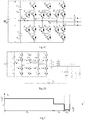
- FIG. 1A shows a three-phase diode-clamped NPC three-level topological structure, of which a DC side is a capacitance bridge arm consisting of two (groups) of capacitors connected in series and having a capacity of C, wherein the upper and lower capacitors may be formed of one or more capacitor devices.
- the three-level topological structure has a phenomenon of an unbalance of the neutral point voltage, i.e., the voltages of the upper and lower capacitors are not the same.
- the unbalance issue of the neutral point voltage is always difficult to be solved, and especially under the working conditions of pure reactive, unbalanced and non-linear AC load, the unbalance of the neutral point voltage on the DC side easily occurs.
- the present invention designs a control method for balancing neutral point voltage of a three-level circuit.
- the present invention relates to a control method for balancing neutral point voltage of a neutral point clamped three-level circuit, wherein the three-level circuit is for converting a DC voltage into a three-phase AC voltage, wherein the three-level circuit comprises a capacitance bridge arm including upper and lower capacitors connected in series and three switch bridge arms electrically connected to the capacitance bridge arm and being a, b and c phase switch bridge arms, respectively, each of the a, b and c phase switch bridge arms includes at least four switch devices to output a positive level, a zero level, or a negative level, characterized in that the method comprises:
- the present invention further relates to a three-level circuit for converting a DC voltage into a three-phase AC voltage
- the three-level circuit comprises a capacitance bridge arm including upper and lower capacitors connected in series and three switch bridge arms electrically connected the capacitance bridge arm and being a, b and c phase switch bridge arms, respectively, wherein each of the a, b and c phase switch bridge arms includes at least four switch devices to output a positive level, a zero level, or a negative level, and wherein the three-level circuit adopts a control method for balancing neutral point voltage of a three-level circuit.
- the present invention further relates to a control method for balancing a neutral point voltage of a neutral point clamped three-level circuit, wherein the three-level circuit is for converting a DC voltage into a three-phase AC voltage and comprises a capacitance bridge arm including upper and lower capacitors connected in series and three switch bridge arms electrically connected the capacitance bridge arm and being a, b and c phase switch bridge arms, respectively, each of which includes at least four switch devices to output a positive level, a zero level, or a negative level, characterized in that it comprises:
- the present invention further relates to a three-level circuit for converting a DC voltage into a three-phase AC voltage, wherein the three-level circuit comprises a capacitance bridge arm including upper and lower capacitors connected in series, and three switch bridge arms electrically connected the capacitance bridge arm and being a, b and c phase switch bridge arms, respectively, each of which includes at least four switch devices to output a positive level, a zero level, or a negative level, and wherein the three-level circuit adopts a control method for balancing a neutral point voltage of a three-level circuit.
- the three-level control method of the present invention can obtain an optimum performance of controlling an unbalance of the neutral point can be acquired and is convenient for implementing, such that it facilitates application of the three-level topology in various operating environments.
- the conventional three-level control methods relate to space vector-based control methods and carrier-wave-based control methods.
- the space vector methods are complex in implementing, and are poor in modulation effect under the circumstance of large modulation degree and low power factor.
- a common used carrier-wave-based control method is zero sequence voltage injection, which is simple in implementing as compared to the space vector methods.
- the space vector methods and the zero sequence voltage injection are not suitable for a three-phase four-wire electrical system as the zero sequence voltage injection may cause neutral current out of control.
- the present invention discloses a control method for balancing a neutral point voltage of a three-level circuit. But the present invention is not limited to be used in three-phase four-wire electrical system.
- the hardware circuit topology suitable for the control method of the present invention may be a neutral point clamped three-level circuit, for example, a DNPC (Diode Neutral Point Clamped) three-level circuit topology shown in FIG. 1A .
- the three-level circuit is for converting a DC voltage into a three-phase AC voltage.
- the three-level circuit comprises a capacitance bridge arm on a DC side including upper and lower capacitors connected in series, and at least three switch bridge arms on an AC side, each of the switch bridge arms of the three-level circuit including at least four switch devices to output a positive level, a zero level, or a negative level.
- the upper and lower capacitors may include one or more capacitor devices, respectively.
- the present invention is not limited thereto.
- the upper and lower capacitors C d 1 and C d 2 may have the same capacity, and the phenomenon of unbalance of the neutral point voltage refers to the phenomenon that a voltage of the upper capacitor is not the same as a voltage of the lower capacitor.
- a variant x represents one of the a, b and c phases
- a duty ratio of the zero level of the x phase in a modulation period (or a switch period) T is d xo
- a duty ratio of the positive level is d xp
- a duty ratio of the negative level is d xn
- a sum thereof is 1.
- d xo + d xp + d xn 1
- u xref represents a modulating reference voltage of the x phase.
- the modulating reference voltage may be predesigned by the control system, and also may be obtained by receiving calculation of an external feedback, or by receiving an external instruction.
- u d represents a DC voltage.
- u d may also equal to a sum of voltages of the upper and lower capacitors.
- the three-level inverter When the duty ratio d xo of the zero level is zero, the three-level inverter is completely degraded to a two-level inverter, and does not have advantages of the three-level inverter such as small harmonic wave and small amplitude of level jump.
- the present invention does not set the duty ratio d xo of the zero level to be zero.
- d xo , d xp and d xn are three unknown numbers, and d xo > 0, d xp ⁇ 0 and d xn ⁇ 0, so the duty ratio d xo of the zero level is adjustable within a value range.
- the neutral point voltage u o is often used to represent an unbalanced degree of the three-level circuit, and may be used to represent a voltage difference between the upper and lower capacitors.
- the neutral point voltage u o can be adjusted by adjusting a size of the duty ratio d xo of the zero level, i.e., the duty ratio d xo of the zero level is adjusted to suppress the phenomenon of the unbalance of the neutral point voltage.
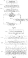
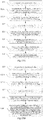
- FIG. 3A is a flow chart of the control method for balancing a neutral point voltage of a three-level circuit in the first embodiment of the present invention. Please refer to FIG. 3A , this embodiment comprises:
- steps S13, S14 and S15 may be merged to one step S13', as shown in FIG. 3B , i.e., when the absolute value of the first neutral point voltage is larger than the first threshold value, adjusting the first set value to be within the first value range, distributing the second set value for the duty ratio of the positive level of the x phase switch bridge arm and the third set value for the duty ratio of the negative level of the x phase switch bridge arm on the basis of the adjusted first set value, and modulating switch devices of the x phase switch bridge arm according to the adjusted first, second and third set values, such that, in one or more cycles or even in the long run, the absolute value of the first neutral point voltage is smaller than the first threshold value.
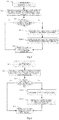
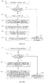
- FIG. 4A is a flow chart of the control method for balancing a neutral point voltage of a three-level circuit according to the second embodiment of the present invention.
- the steps S11, S13, S14 and S15 are the same as the corresponding steps in the first embodiment, and the steps S13, S14 and S15 may also be merged to the step S13', as shown in FIG. 4B , so the details will not be described here.
- step S12-2 is executed to preset the first set value d xo as the maximum value d xo max of the first value range.
- decreasing the duty ratio d xo of the zero level may reduce switching time among the three levels, thereby reducing switch loss.
- FIG. 5 is a flow chart of the control method for balancing neutral point voltage of a three-level circuit according to the third embodiment of the present invention.
- the steps S11, S12, S13 and S15 are the same as the corresponding steps in the first embodiment, and the steps S13, S14 and S15 may also be merged, so the details will not be described here.
- This embodiment differs from the first embodiment in that the step 14 may be further refined.
- step S14-1 is executed to adjust the first set value d xo of the duty ratio of the zero level of the x phase switch bridge arm on the basis of the first neutral point voltage and a flow direction of a current of the x phase, specifically, when it is determined that the voltage of the upper capacitor of the capacitance bridge arm is larger than the voltage of the lower capacitor: decreasing the first set value d xo of the duty ratio of the zero level of the x phase when the current of the x phase flows from the three-level circuit to the load, and increasing the first set value d xo of the duty ratio of the zero level of the x phase when the current of the x phase flows from the load to the three-level circuit; when the voltage of the upper capacitor of the capacitance bridge arm is smaller than the voltage of the lower capacitor: increasing the first set value d xo of the duty ratio of the zero level of the x phase when the current of the x phase flows from the three-
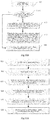
- FIG. 6 is a flow chart of the control method for balancing neutral point voltage of a three-level circuit according to the fourth embodiment of the present invention.
- the steps S11, S12, S13 and S15 are the same as the corresponding steps in the first embodiment, and the steps S13, S14 and S15 may also be merged, so the details will not be described here.
- This embodiment differs from the first embodiment in that the step 14 may be further refined.
- step S14-3 may be executed to distribute the second set value d xp of the x phase and the third set value d xn of the x phase on the basis of the adjusted first set value d xo , and modulate the switch devices of the x phase switch bridge arm according to the adjusted first, second and third set values d xo , d xp and d xn .
- k p is a proportioncontrol parameter.
- the first set value d xo of the duty ratio of the zero level may be further adjusted using, such as, proportional-integral and proportional-resonant controllers.
- the preferable formula may decrease the duty ratio d xo of the zero level on the basis of presetting the duty ratio d xo of the zero level as the maximum value d xo max , and when the output current i x of the x phase and the neutral point voltage u o have different signs, the duty ratio d xo of the zero level of the x phase may not change, such that only adjusting the duty ratio d xp of the positive level and the duty ratio d xn of the negative level of the x phase can reduce the switching times among the three levels, thereby reducing switch loss.
- FIG. 7 is a flow chart of the control method for balancing neutral point voltage of a three-level circuit according to the fifth embodiment of the present invention.
- the steps S11, S12, S13, S14-1 and S15 are the same as the corresponding steps in the above embodiments, and the steps S13 to S15 may also be merged, so the details will not be described here.
- This embodiment differs from the first embodiment in that the step 14 may be further refined.
- step S14-5 may be executed to modulate the switch devices of the x phase switch bridge arm according to the adjusted first, second and third set values d xo , d xp and d xn .
- an output voltage of at least one bridge arm may include a positive level, a negative level and a zero level in at least one switch period, as shown in (a) and (c) of FIG. 9 , where output voltages of the two bridge arms include positive, negative and zero levels in one switch period.
- FIG. 9 in one to more switch periods, when the modulating reference voltages of the a, b and c phases are different, the duty ratios of the zero levels of the a, b and c phases are different.
- FIG. 8 is a flow chart of the control method for balancing neutral point voltage of a three-level circuit according to the sixth embodiment of the present invention.
- the steps S11, S12, S13, S14 and S15 are the same as the corresponding steps in the first embodiment, so the details will not be described here.
- the first set value d xo is adjusted, the second set value d xp and the third set value d xn are distributed on the basis of the adjusted first set value d xo , and the switch devices of the x phase switch bridge arm are modulated correspondingly.
- the adjusted first, second and third set values d xo , d xp and d xn of the x phase switch bridge arm do not equal to zero, such that the output voltage of the x phase switch bridge arm includes the positive level, the negative level and the zero level in at least one switch period.
- the sixed embodiment is continued in the seventh embodiment. As shown in the dashed box of FIG.
- step S14-6 i.e., when the adjusted first, second and third set values d xo , d xp and d xn of the x phase switch bridge arm do not equal to zero, such that the output voltage of the x phase switch bridge arm includes the positive level, the negative level and the zero level in at least one switch period, as described in step S14-7, output voltages of at least two of the a, b and c phase switch bridge arms including the x phase switch bridge arm of the three-level circuit include the positive level, the negative level and the zero level in at least one switch period, and the results are shown in FIG. 9 .
- control method for balancing neutral point voltage of a three-level circuit modulates by use of positive, negative and zero levels, such that the duty ratio of the zero level of the x phase voltage is adjustable, suppresses the unbalance of the neutral point with the adjustable zero level, may not inject the zero sequence voltage, and may be applied to a three-phase three wire system and a three-phase four wire system.
- zero sequence voltage injection may also be adopted, such that the present invention produces more significant technical effect in the three-phase three wire electrical system, such as, reducing switching times, reducing loss, etc.
- FIG. 10A is a flow chart of the control method for balancing neutral point voltage of a three-level circuit according to the eighth embodiment of the present invention.
- the steps S11, S12, S13, S14 and S15 are the same as the corresponding steps in the first embodiment, and the steps S13, S14 and S15 may also be merged to the step S13', as shown in FIG. 10B , so the details will not be described here.
- This embodiment differs from the first embodiment in executing step S11-1 to set a second threshold value after obtaining the first neutral point voltage u o in the step S11.
- step S12 is executed, and if the first neutral point voltage u o is smaller than the second threshold value, and the unbalanced degree of the neutral point is low, step S16 is executed to inject the zero sequence voltage to control the balance of the neutral point voltage.
- the second threshold value is smaller than or equals to the first threshold value in the step S13.
- the step S11-1 may be further merged to the step S13; when the first neutral point voltage u o is smaller than the first threshold value, the step S16 is executed to inject the zero sequence voltage; and when the first neutral point voltage u o is larger than the first threshold value, the step S14 is executed. Since the zero sequence voltage may be injected, this embodiment is suitable for the three-phase three wire electrical system. The zero sequence voltage injection in this embodiment belongs to the prior art, so the details will not be described here.
- FIG. 11A is a flow chart of the control method for balancing neutral point voltage of a three-level circuit according to the ninth embodiment of the present invention. As shown in FIG. 11A , this embodiment comprises:
- the steps S22 and S23 are listed separately for convenience of expression, and may be merged to step S22', and the steps S24, S25 and S26 may also be merged to step S24', as shown in FIG. 11B .
- the second set value of the duty ratio of the positive level of the x phase switch bridge arm and the third set value of the duty ratio of the negative level of the x phase switch bridge arm are distributed on the basis of the first set value, and the switch devices of the x phase switch bridge arm are modulated according to the first, second and third set values, such that an output voltage of the x phase switch bridge arm includes positive, negative and zero levels in at least one switch period, and an absolute value of the first neutral point voltage is smaller than a first threshold value.
- FIG. 13A is a flow chart of the control method for balancing neutral point voltage of a three-level circuit according to the tenth embodiment of the present invention.
- the steps S21, S23, S24, S25 and S26 are the same as the corresponding steps in the ninth embodiment, the steps S22 and S23 may be merged, and the steps S24, S25 and S26 may also be merged to the step S24', as shown in FIG. 13B , so the details will not be described here.
- This embodiment differs from the ninth embodiment in that the step S22 may be further refined.
- step S22-1 acquires the maximum value d xo max of the first value range (0, d xo max ] of the duty ratio d xo of the zero level of the x phase switch bridge arm by use of the above formula (4), thereby selecting one value in the acquired first value range (0, d xo max ] as a preset value of the first set value d xo , and then the step S23 is executed.
- Another embodiment is a continuation of the tenth embodiment, as shown in the dashed box of FIG. 13A .
- the step S22-1 completes, i.e., after acquiring the maximum value d xo max of the first value range (0, d xo max ] of the duty ratio d xo of the zero level of the x phase switch bridge arm, it further comprises step S22-2 to preset the first set value d xo as the maximum value d xo max of the first value range, and then the step S23 is executed.
- FIG. 14A is a flow chart of the control method for balancing neutral point voltage of a three-level circuit according to the eleventh embodiment of the present invention.
- the steps S21, S22, S23, S24, S25 and S26 are the same as the corresponding steps in the ninth embodiment, the steps S22 and S23 may be merged to the step S22', and the steps S24, S25 and S26 may also be merged to the step S24', as shown in FIG. 14B , so the details will not be described here.
- This embodiment differs from the ninth embodiment in that the step S21-1 may be executed to set a second threshold value after obtaining the first neutral point voltage u o in the step S21.
- step S22 is executed, and if the first neutral point voltage u o is smaller than the second threshold value, step S27 may be executed to inject the zero sequence voltage to control the balance of the neutral point voltage.
- the method of this embodiment is suitable for a three-phase three wire electrical system.
- the zero sequence voltage injection in this embodiment belongs to the prior art, so the details will not be described here.
- the control method for balancing neutral point voltage of a three-level circuit disclosed in respective embodiments of the present invention is suitable for a three-level circuit, which is for converting a DC voltage into a three-phase AC voltage and comprises a capacitance bridge arm including upper and lower capacitors connected in series, and three switch bridge arms electrically connected the capacitance bridge arm and being a, b and c phase switch bridge arms, respectively, each of which includes at least four switch devices to output a positive level, a zero level, or a negative level.
- the three-level circuit may be applied to a three-phase four wire electrical system, and also may be applied to a three-phase three wire electrical system.
- the three-level circuit is connected to a LC filter including at least three filter capacitors in star connection, and a neutral point of connection of the filter capacitors is electrically connected to a connection point of the upper and lower capacitors of the three-level circuit.
- the three-level circuit further comprises a fourth switch bridge arm electrically connected to the capacitance bridge arm and having the same topology as the a, b and c phase switch bridge arms.
- control method for balancing neutral point voltage of a three-level circuit disclosed in the embodiments is suitable for a plurality of NPC (neutral point clamped) three-level circuits, as shown in FIGS. 1A, 1B , 1C and ID.
- FIG. 1A, 1B , 1C and ID the control method for balancing neutral point voltage of a three-level circuit disclosed in the embodiments.
- the capacitance bridge arm includes an upper capacitor C d 1 and a lower capacitor C d 2 connected in series, a first end of the upper capacitor is electrically connected to a first DC input end, a second end of the upper capacitor is electrically connected to a neutral point level end, a first end of the lower capacitor is electrically connected to the neutral point level end, and a second end of the lower capacitor is electrically connected to a second DC input end; the first and second DC input ends of the capacitance bridge arm are electrically connected to the input voltage u d on the DC side; it further comprises a, b and c switch bridge arms to output a positive level or a zero level or a negative level.
- the a phase switch bridge arm has four switch devices, and these switch devices in this embodiment are IGBT, which are respectively S a 1 , S a 2 , S a 3 , S a 4 , and two clamped diodes, which are respectively D a 1 , D a 2 , wherein S a 1 , S a 2 , S a 3 and S a 4 are connected to the capacitance bridge arm in parallel after being sequentially connected in series, D a 1 and D a 2 are connected to S a 2 and S a 3 in parallel after being sequentially connected in series, connecting ends of D a 1 and D a 2 are electrically connected to a neutral point (i.e., a neutral point level end) O of the capacitance bridge arm, and connecting ends of S a 2 and S a 3 are AC output ends of the a phase switch bridge arm.
- IGBT IGBT
- S a 1 , S a 2 , S a 3 , S a 4 IGBT
- the b and c phase switch bridge arms may have the same structure as the a phase switch bridge arm, as shown in FIG. 1A , the switch devices and the diodes of the b phase switch bridge arm are shown by S b 1 , S b 2 , S b 3 , S b 4 , and D b 1 , D b 2 , and the switch devices and the diodes of the c phase switch bridge arm are shown by S c 1 , S c 2 , S c 3 , S c 4 , and D c 1 , D c2 .
- any one of the a, b and c phase switch bridge arms includes a first switch device, a second switch device, a third switch device, a fourth switch device, a first diode and a second diode; a first end of the first switch device is electrically connected to the first end of the upper capacitor, a second end of the first switch device is electrically connected to a first end of the second switch device, a second end of the second switch device is electrically connected to a first end of the third switch device, a second end of the third switch device is electrically connected to a first end of the fourth switch device, a second end of the fourth switch device is electrically connected to the second end of the lower capacitor; an anode of the first diode and a cathode of the second diode are electrically connected to the neutral point level end, a cathode of the first diode is electrically connected to the second end of the first switch device, and an anode of the second diode is electrically connected to the second end of
- the DNPC three-level circuit topology shown in FIG. 1A further comprises an analog-to-digital sampling module and a digital signal processing module for signal sampling and PWM generation.
- the analog-to-digital sampling module is for collecting parameters of the voltage u d 1 of upper capacitor, the voltage u d 2 of the lower capacitor, the output voltage i x of the x phase and the like
- the digital signal processing module is for modulating an instruction of driving the switch devices of the x phase switch bridge arm.
- the DNPC three-level circuit topology shown in FIG. 1A further comprises a LC filter.
- the LC filter includes at least three filter capacitors C in star connection, and an inductor L on the AC output end of each phase.
- Neutral point of connection n c of these filter capacitors C may be electrically connected to the neutral point level end O and applied to the three-phase four wire electrical system, and may also not be connected and applied to the three-phase three wire electrical system.
- the present invention is not limited thereto.
- the three-phase four wire electrical system may also electrically connect the neutral point n of the load Z to the neutral point level end O.
- the control method for balancing neutral point voltage of a three-level circuit disclosed in the embodiment may also be applied to a T-type three-level circuit topology, as shown in FIG. 1B , of which the capacitance bridge arm is the same as the DNPC three-level circuit topology, and further comprises a, b and c switch bridge arms.
- the a phase bridge arm has four switch devices, for example, IGBT, which are respectively S a 1 , S a 2 , S a 3 , S a 4 , wherein S a 1 and S a 4 are connected to the capacitance bridge arm in parallel after being sequentially connected in series, and after S a 2 and S a 3 are connected in series reversely, one end is electrically connected to the neutral point level end O, the other end is electrically connected to connecting ends of S a 1 and S a 4 , and the connecting ends of S a 1 and S a 4 are AC output ends of the a phase switch bridge arm.
- IGBT switch devices
- the b and c phase switch bridge arms may have the same structure as the a phase switch bridge arm, as shown in FIG. 1B , the switch devices of the b phase switch bridge arm are shown by S b 1 , S b 2 , S b 3 , S b 4 , and the switch devices of the c phase switch bridge arm are shown by S c 1 , S c 2 , S c 3 , S c 4 .
- any one of the a, b and c phase switch bridge arms includes a first switch device, a second switch device, a third switch device and a fourth switch device; a first end of the first switch device is electrically connected to the first end of the upper capacitor, a second end of the first switch device is electrically connected to a first end of the fourth switch device and a second end of the third switch device, a first end of the second switch device is electrically connected to a first end of the third switch device, a second end of the second switch device is electrically connected to the neutral point level end, and a second end of the fourth switch device is electrically connected to the second end of the lower capacitor.
- the control method for balancing neutral point voltage of a three-level circuit disclosed in the embodiment may also be applied to an ANPC three-level circuit topology, as shown in FIG. 1C , of which the capacitance bridge arm is the same as the DNPC three-level circuit topology, and further comprises a, b and c switch bridge arms.
- the a phase bridge arm has six switch devices, for example, IGBT, which are respectively S a 1 , S a 2 , S a 3 , S a 4 , S a 5 , S a 6 , wherein S a 1 , S a 2 , S a 3 and S a 4 are connected to the capacitance bridge arm in parallel after being sequentially connected in series, S a 5 and S a 6 are connected to S a 2 and S a 3 in parallel after being sequentially connected in series, connecting ends of S a 5 and S a 6 are electrically connected to the neutral point level end O, and connecting ends of S a 2 and S a 3 are AC output ends of the a phase bridge arm.
- IGBT six switch devices, for example, IGBT, which are respectively S a 1 , S a 2 , S a 3 , S a 4 , S a 5 , S a 6 , wherein S a 1 , S a 2 , S a 3 and S
- the b and c phase switch bridge arms may have the same structure as the a phase switch bridge arm, as shown in FIG. 1B , the switch devices of the b phase switch bridge arm are shown by S b 1 , S b 2 , S b 3 , S b 4 , S b 5 , S a 6 , and the switch devices of the c phase switch bridge arm are shown by S c 1 , S c 2 , S c 3 , S c 4 , S c 5 , S c 6 .
- any one of the a, b and c phase switch bridge arms includes a first switch device, a second switch device, a third switch device, a fourth switch device, a fifth switch device and a sixth switch device; a first end of the first switch device is electrically connected to the first end of the upper capacitor, a second end of the first switch device is electrically connected to a first end of the second switch device and a first end of the fifth switch device, a second end of the second switch device is electrically connected to a first end of the third switch device, a second end of the third switch device is electrically connected to a first end of the fourth switch device and a second end of the sixth switch device, a second end of the fourth switch device is electrically connected to the second end of the lower capacitor, a second end of the fifth switch device is electrically connected to a first end of the sixth switch device and the neutral point level end.
- control method for balancing neutral point voltage of a three-level circuit disclosed in the present may be applied to a three-phase four bridge arm three-level circuit topology, which may be suitable for the three-phase four wire electrical system.
- a three-phase four bridge arm three-level circuit topology which may be suitable for the three-phase four wire electrical system.
- the a phase bridge arm has four IGBT, which are respectively S a 1 , S a 2 , S a 3 , S a 4 , and two clamped diodes, which are respectively D a 1 , D a 2 , wherein S a 1 , S a 2 , S a 3 and S a 4 are connected to the capacitance bridge arm in parallel after being sequentially connected in series, D a 1 and D a 2 are connected to S a 2 and S a 3 in parallel after being sequentially connected in series, connecting ends of D a 1 and D a 2 are electrically connected to the neutral point level end O, and connecting ends of S a 2 and S a 3 are AC output ends of the a phase bridge arm.
- the b and c phase switch bridge arms are the same as the a phase switch bridge arm.
- the n phase switch bridge arm has four IGBT, which are respectively S n 1 , S n 2 , S n 3 , S n 4 , and two clamped diodes, which are respectively D n 1 and D n 2 , wherein S n 1 , S n 2 , S n 3 and S n 4 are connected to the capacitance bridge arm in parallel after being sequentially connected in series, D n 1 and D n 2 are connected to S n 2 and S n 3 in parallel after being sequentially connected in series, connecting ends of D n 1 and D n 2 are electrically connected to the neutral point level end O, and connecting ends of S n 2 and S n 3 are electrically connected to neutral wires of the three-phase four wire system.
- This embodiment is applied to, but not limited to the DNPC three-level circuit topology, and may also be applied to the T-type and the ANPC three-level circuits. This embodiment may also further add a LC filter and a neutral wire inductor L '.
Landscapes
- Engineering & Computer Science (AREA)
- Power Engineering (AREA)
- Inverter Devices (AREA)
Abstract
Description
- The present invention relates to the technical field of power electronics, and in particular, the present invention relates to a control method for balancing a neutral point voltage of a three-level circuit, and a three-level circuit using the same.
- Inverter is a device converting a DC current into an AC current, and has a plurality of topological structures, among which three-level topological structure has advantages of large output capacity, high output voltage and small current harmonic content, and is widely applied in the fields of AC motor speed regulation, new energy power generation, energy storage, static var compensation and flexible power transmission. Neutral Point Clamped (NPC) three-level inverter is a common inverter with three-level topological structure, including diode-clamped NPC, T-type NPC, Active Neutral Point Clamped (ANPC) and the like.
FIG. 1A shows a three-phase diode-clamped NPC three-level topological structure, of which a DC side is a capacitance bridge arm consisting of two (groups) of capacitors connected in series and having a capacity of C, wherein the upper and lower capacitors may be formed of one or more capacitor devices. The three-level topological structure has a phenomenon of an unbalance of the neutral point voltage, i.e., the voltages of the upper and lower capacitors are not the same. The unbalance issue of the neutral point voltage is always difficult to be solved, and especially under the working conditions of pure reactive, unbalanced and non-linear AC load, the unbalance of the neutral point voltage on the DC side easily occurs. If this phenomenon is not suppressed, then an output voltage becomes poorer, and an output current becomes worse, causing a DC overvoltage or an AC overcurrent, and a shutdown with failure. Therefore, it is of great importance for wide application of the three-level topology to design a reasonable control method to suppress an unbalance of the neutral point voltage. - In order to solve the above problem, the present invention designs a control method for balancing neutral point voltage of a three-level circuit.
- To be specific, the present invention relates to a control method for balancing neutral point voltage of a neutral point clamped three-level circuit, wherein the three-level circuit is for converting a DC voltage into a three-phase AC voltage, wherein the three-level circuit comprises a capacitance bridge arm including upper and lower capacitors connected in series and three switch bridge arms electrically connected to the capacitance bridge arm and being a, b and c phase switch bridge arms, respectively, each of the a, b and c phase switch bridge arms includes at least four switch devices to output a positive level, a zero level, or a negative level, characterized in that the method comprises:
-
step 11, obtaining a first neutral point voltage to represent a voltage difference between the upper and lower capacitors; -
step 12, acquiring a first value range of a duty ratio of a zero level of x phase switch bridge arm through a modulating reference voltage of the x phase switch bridge arm and the DC voltage, wherein x represents a, b and c phase switch bridge arms included in the three-level circuit, and presetting a first set value of the duty ratio of zero level of the x phase switch bridge arm within the first value range; -
step 13, when an absolute value of the first neutral point voltage is larger than a first threshold value, adjusting the first set value to be within the first value range, distributing a second set value for a duty ratio of the positive level of the x phase switch bridge arm and a third set value for a duty ratio of the negative level of the x phase switch bridge arm on the basis of the adjusted first set value, and modulating the switch devices of the x phase switch bridge arm according to the adjusted first, second and third set values, such that the absolute value of the first neutral point voltage is smaller than the first threshold value. - The present invention further relates to a three-level circuit for converting a DC voltage into a three-phase AC voltage, wherein the three-level circuit comprises a capacitance bridge arm including upper and lower capacitors connected in series and three switch bridge arms electrically connected the capacitance bridge arm and being a, b and c phase switch bridge arms, respectively, wherein each of the a, b and c phase switch bridge arms includes at least four switch devices to output a positive level, a zero level, or a negative level, and wherein the three-level circuit adopts a control method for balancing neutral point voltage of a three-level circuit.
- The present invention further relates to a control method for balancing a neutral point voltage of a neutral point clamped three-level circuit, wherein the three-level circuit is for converting a DC voltage into a three-phase AC voltage and comprises a capacitance bridge arm including upper and lower capacitors connected in series and three switch bridge arms electrically connected the capacitance bridge arm and being a, b and c phase switch bridge arms, respectively, each of which includes at least four switch devices to output a positive level, a zero level, or a negative level, characterized in that it comprises:
-
step 21, obtaining a first neutral point voltage to represent a voltage difference between the upper and lower capacitors; -
step 22, adjusting a first set value of a duty ratio of zero level of the x phase switch bridge arm, such that in a same switch period, when modulating reference voltages of the a, b and c phase switch bridge arms are different, duty ratios of the zero levels of the a, b and c phase switch bridge arms are different, wherein x represents the a, b and c phase switch bridge arms included in the three-level circuit; -
step 23, distributing a second set value for a duty ratio of the positive level of the x phase switch bridge arm and a third set value for a duty ratio of the negative level of the x phase switch bridge arm on the basis of the first set value, and modulating the switch devices of the x phase switch bridge arm according to the first, second and third set values, such that an output voltage of the x phase switch bridge arm includes positive, negative and zero levels in at least one switch period, and an absolute value of the first neutral point voltage is smaller than a first threshold value. - The present invention further relates to a three-level circuit for converting a DC voltage into a three-phase AC voltage, wherein the three-level circuit comprises a capacitance bridge arm including upper and lower capacitors connected in series, and three switch bridge arms electrically connected the capacitance bridge arm and being a, b and c phase switch bridge arms, respectively, each of which includes at least four switch devices to output a positive level, a zero level, or a negative level, and wherein the three-level circuit adopts a control method for balancing a neutral point voltage of a three-level circuit.
- In conclusion, as compared to the prior art, the three-level control method of the present invention can obtain an optimum performance of controlling an unbalance of the neutral point can be acquired and is convenient for implementing, such that it facilitates application of the three-level topology in various operating environments.
-
-
FIG. 1A is a topological diagram of a DNPC three-level circuit used in the embodiment of the present invention. -
FIG. 1B is a topological diagram of a T-type NPC three-level circuit used in the embodiment of the present invention. -
FIG. 1C is a topological diagram of an ANPC three-level circuit used in the embodiment of the present invention. - FIG. ID is a topological diagram of a three-phase four bridge arm NPC three-level circuit used in the embodiment of the present invention.
-
FIG. 2 is a schematic diagram of duty ratios of positive, negative and zero levels of x phase in the method of controlling a balance of a neutral point voltage of a three-level circuit in the embodiment of the present invention. -
FIGS. 3A and 3B are flow charts of the first embodiment of the present invention. -
FIGS. 4A and 4B are flow charts of the second embodiment of the present invention. -
FIG. 5 is a flow chart of the third embodiment of the present invention. -
FIG. 6 is a flow chart of the fourth embodiment of the present invention. -
FIG. 7 is a flow chart of the fifth embodiment of the present invention. -
FIG. 8 is a flow chart of the sixth embodiment of the present invention. -
FIG. 9 is a schematic diagram when output voltages of two of the a, b and c phase switch bridge arms include the positive level, the negative level and the zero level in one switch period of the sixth embodiment of the present invention. -
FIGS. 10A and10B are flow charts of the eighth embodiment of the present invention. -
FIGS. 11A and11B are flow charts of the ninth embodiment of the present invention. -
FIG. 12A is a schematic diagram of changes of modulating reference voltages of the a, b and c phase switch bridge arms in the ninth embodiment of the present invention. -
FIG. 12B is a schematic diagram of changes of the duty ratios of the zero levels of the a, b and c phase switch bridge arms in the ninth embodiment of the present invention. -
FIGS. 13A and 13B are flow charts of the tenth embodiment of the present invention. -
FIGS. 14A and 14B are flow charts of the eleventh embodiment of the present invention. - The present invention is further described in detail below with reference to the drawings.
- With respect to the phenomenon of an unbalance of the neutral point voltage, the conventional three-level control methods relate to space vector-based control methods and carrier-wave-based control methods. The space vector methods are complex in implementing, and are poor in modulation effect under the circumstance of large modulation degree and low power factor. A common used carrier-wave-based control method is zero sequence voltage injection, which is simple in implementing as compared to the space vector methods. However, the space vector methods and the zero sequence voltage injection are not suitable for a three-phase four-wire electrical system as the zero sequence voltage injection may cause neutral current out of control. In order to remedy some deficiencies of the existing algorithms, the present invention discloses a control method for balancing a neutral point voltage of a three-level circuit. But the present invention is not limited to be used in three-phase four-wire electrical system.
- The hardware circuit topology suitable for the control method of the present invention may be a neutral point clamped three-level circuit, for example, a DNPC (Diode Neutral Point Clamped) three-level circuit topology shown in
FIG. 1A . The three-level circuit is for converting a DC voltage into a three-phase AC voltage. The three-level circuit comprises a capacitance bridge arm on a DC side including upper and lower capacitors connected in series, and at least three switch bridge arms on an AC side, each of the switch bridge arms of the three-level circuit including at least four switch devices to output a positive level, a zero level, or a negative level. The upper and lower capacitors may include one or more capacitor devices, respectively. The present invention is not limited thereto. The upper and lower capacitors C d1 and C d2 may have the same capacity, and the phenomenon of unbalance of the neutral point voltage refers to the phenomenon that a voltage of the upper capacitor is not the same as a voltage of the lower capacitor. - The switch bridge arms on the AC side of the NPC three-level circuit are referred to as a, b and c phases. A variant x represents one of the a, b and c phases, a duty ratio of the zero level of the x phase in a modulation period (or a switch period) T is dxo , a duty ratio of the positive level is dxp , a duty ratio of the negative level is dxn , and a sum thereof is 1. As shown in
FIG. 2 , i.e., they satisfy:
FIG. 1A , ud may also equal to a sum of voltages of the upper and lower capacitors. According to the area equivalence principle, the duty ratios of the positive, negative and zero levels of each phase satisfy:
- When the duty ratio dxo of the zero level is zero, the three-level inverter is completely degraded to a two-level inverter, and does not have advantages of the three-level inverter such as small harmonic wave and small amplitude of level jump. The present invention does not set the duty ratio dxo of the zero level to be zero.
- In the formulas (1) and (2), dxo , dxp and dxn are three unknown numbers, and dxo > 0, dxp ≥0 and dxn ≥0, so the duty ratio dxo of the zero level is adjustable within a value range.
- The neutral point voltage uo is often used to represent an unbalanced degree of the three-level circuit, and may be used to represent a voltage difference between the upper and lower capacitors. In the corresponding circuit topology shown in the figures, generally, the neutral point voltage uo satisfies a mathematic model:

- Right of the formula (3) is an average current iNP flowing out from the neutral point O of the capacitance bridge arm in one switch period, ix is an AC output current of the x phase bridge arm, the definition ix >0 represents that the current flows from the inverter to the load, ix <0 represents that the current flows from the load to the inverter, in represents a current in a neutral wire, and if the neutral wire does not exist, in =0. According to the formula (3), the neutral point voltage uo can be adjusted by adjusting a size of the duty ratio dxo of the zero level, i.e., the duty ratio dxo of the zero level is adjusted to suppress the phenomenon of the unbalance of the neutral point voltage.
-
FIG. 3A is a flow chart of the control method for balancing a neutral point voltage of a three-level circuit in the first embodiment of the present invention. Please refer toFIG. 3A , this embodiment comprises: - step S11, acquiring a first neutral point voltage uo. The first neutral point voltage uo may be acquired through several methods, for example, sampling voltages u d1 and u d2 of the upper and lower capacitors on the DC end, and obtaining the first neutral point voltage uo =(u d1-u d2)/2. The first neutral point voltage uo may also be acquired through other method, for example, uo = u d1 - u d2, uo = ud - 2*u d2, etc., which can represent a voltage difference between the upper and lower capacitors, i.e., which represent the unbalanced degree of the three-level circuit;
- step S12, acquiring a value range of the first set value dxo of a duty ratio of a zero level of x phase switch bridge arm through the modulating reference voltage uxref and the DC voltage ud of the x phase, and preselecting one value in the value range as a preset value of the first set value dxo ;
- step S13, determining whether a balance of the first neutral point voltage uo has to be balance-controlled, particularly determining whether the first neutral point voltage uo is larger than a first threshold value uth, and when an absolute value of the first neutral point voltage uo is smaller than the first threshold value uth, it may be viewed that the first neutral point voltage uo reaches a balanced state. At this time, it may not be processed or may be controlled using the conventional zero sequence voltage injection. The present invention is not limited thereto. When the absolute value of the first neutral point voltage uo is larger than the first threshold value uth, the balance of the first neutral point voltage uo is controlled according to subsequent control method;
- step S14, when the absolute value of the first neutral point voltage uo is larger than the first threshold value uth, adjusting the first set value dxo of the x phase within the first value range, the adjusted first set value being still within the first value range, distributing the second set value dxp of the duty ratio of the positive level of the x phase and the third set value dxn of the duty ratio of the negative level of the x phase on the basis of the adjusted first set value, and modulating switch devices of the x phase according to the adjusted first, second and third set values dxo , dxp and dxn in one or more switch periods, so as to reduce the absolute value of the first neutral point voltage uo ;
- step S15, when the absolute value of the first neutral point voltage uo is smaller than the first threshold value uth, it may be viewed as reaching a balanced state of the first neutral point voltage uo.
- The above steps may be merged or split to be viewed still as the same method contents. For examples, the steps S13, S14 and S15, which are listed separately for convenience of expression, may be merged to one step S13', as shown in
FIG. 3B , i.e., when the absolute value of the first neutral point voltage is larger than the first threshold value, adjusting the first set value to be within the first value range, distributing the second set value for the duty ratio of the positive level of the x phase switch bridge arm and the third set value for the duty ratio of the negative level of the x phase switch bridge arm on the basis of the adjusted first set value, and modulating switch devices of the x phase switch bridge arm according to the adjusted first, second and third set values, such that, in one or more cycles or even in the long run, the absolute value of the first neutral point voltage is smaller than the first threshold value. -
FIG. 4A is a flow chart of the control method for balancing a neutral point voltage of a three-level circuit according to the second embodiment of the present invention. Please refer toFIG. 4A , in this embodiment, the steps S11, S13, S14 and S15 are the same as the corresponding steps in the first embodiment, and the steps S13, S14 and S15 may also be merged to the step S13', as shown inFIG. 4B , so the details will not be described here. This embodiment differs from the first embodiment in executing step S12-1, specifically, i.e., acquiring the maximum value d xomax of the first value range (0, d xomax] of the duty ratio dxo of the zero level of the x phase switch bridge arm using formula (4), after the step S11, i.e., after obtaining the first neutral point voltage uo,
- Another embodiment is a continuation of the second embodiment, as shown in the dashed box of
FIG. 4A . As compared to the second embodiment, after the step S12-1 completes, i.e., after acquiring the maximum value d xomax in the first value range (0, d xomax] of the duty ratio dxo of the zero level of the x phase switch bridge arm, step S12-2 is executed to preset the first set value dxo as the maximum value d xomax of the first value range. As compared to optionally select one value in the adjustable range as a preset value, on the basis of presetting the duty ratio dxo of the zero level as the maximum value d xomax, decreasing the duty ratio dxo of the zero level may reduce switching time among the three levels, thereby reducing switch loss. -
FIG. 5 is a flow chart of the control method for balancing neutral point voltage of a three-level circuit according to the third embodiment of the present invention. Please refer toFIG. 5 , in this embodiment, the steps S11, S12, S13 and S15 are the same as the corresponding steps in the first embodiment, and the steps S13, S14 and S15 may also be merged, so the details will not be described here. This embodiment differs from the first embodiment in that thestep 14 may be further refined. When the first neutral point voltage uo is larger than the first threshold value uth, step S14-1 is executed to adjust the first set value dxo of the duty ratio of the zero level of the x phase switch bridge arm on the basis of the first neutral point voltage and a flow direction of a current of the x phase, specifically, when it is determined that the voltage of the upper capacitor of the capacitance bridge arm is larger than the voltage of the lower capacitor: decreasing the first set value dxo of the duty ratio of the zero level of the x phase when the current of the x phase flows from the three-level circuit to the load, and increasing the first set value dxo of the duty ratio of the zero level of the x phase when the current of the x phase flows from the load to the three-level circuit; when the voltage of the upper capacitor of the capacitance bridge arm is smaller than the voltage of the lower capacitor: increasing the first set value dxo of the duty ratio of the zero level of the x phase when the current of the x phase flows from the three-level circuit to the load, and decreasing the first set value dxo of the duty ratio of the zero level of the x phase when the current of the x phase flows from the load to the three-level circuit; after the step S14-1, step S14-3 may be executed to distribute the second set value dxp of the x phase and the third set value dxn of the x phase on the basis of the adjusted first set value dxo , and modulate the switch devices of the x phase switch bridge arm according to the adjust first, second and third set values dxo , dxp and dxn. -
FIG. 6 is a flow chart of the control method for balancing neutral point voltage of a three-level circuit according to the fourth embodiment of the present invention. Please refer toFIG. 6 , in this embodiment, the steps S11, S12, S13 and S15 are the same as the corresponding steps in the first embodiment, and the steps S13, S14 and S15 may also be merged, so the details will not be described here. This embodiment differs from the first embodiment in that thestep 14 may be further refined. When the first neutral point voltage uo is larger than the first threshold value uth, step S14-2 may be executed to adjust the first set value dxo of the duty ratio of the zero level of the x phase switch bridge arm according to formula (5):
- Then, step S14-3 may be executed to distribute the second set value dxp of the x phase and the third set value dxn of the x phase on the basis of the adjusted first set value dxo , and modulate the switch devices of the x phase switch bridge arm according to the adjusted first, second and third set values dxo , dxp and dxn.
- In this embodiment, kp is a proportioncontrol parameter. The larger the proportioncontrol parameter kp is, the faster the speed for suppressing the unbalance will be. Generally, it is selected as a compromise betweenstability and rapidity of suppressing the neutral point voltage, so in some embodiments, it may be selected as

- The benefit of using the formula (5) is that, as compared to optically select one value in the adjustable range as a preset value, the preferable formula may decrease the duty ratio dxo of the zero level on the basis of presetting the duty ratio dxo of the zero level as the maximum value d xomax, and when the output current ix of the x phase and the neutral point voltage uo have different signs, the duty ratio dxo of the zero level of the x phase may not change, such that only adjusting the duty ratio dxp of the positive level and the duty ratio dxn of the negative level of the x phase can reduce the switching times among the three levels, thereby reducing switch loss.
-
FIG. 7 is a flow chart of the control method for balancing neutral point voltage of a three-level circuit according to the fifth embodiment of the present invention. Please refer toFIG. 7 , in this embodiment, the steps S11, S12, S13, S14-1 and S15 are the same as the corresponding steps in the above embodiments, and the steps S13 to S15 may also be merged, so the details will not be described here. This embodiment differs from the first embodiment in that thestep 14 may be further refined. After the step S14-1, i.e., after adjusting the first set value dxo of the duty ratio of the zero level of the x phase switch bridge arm, step S14-4 is executed to distribute the second set value dxp of the duty ratio of the positive level of the x phase switch bridge arm and the third set value dxn of the duty ratio of the negative level of the x phase switch bridge arm according to the area equivalence principle through formula (6),
- After the step S14-4, step S14-5 may be executed to modulate the switch devices of the x phase switch bridge arm according to the adjusted first, second and third set values dxo , dxp and dxn.
- When using the methods in respective embodiments of the present invention, on the basis of the different first set value, and the different distributed second and third set values, an output voltage of at least one bridge arm may include a positive level, a negative level and a zero level in at least one switch period, as shown in (a) and (c) of
FIG. 9 , where output voltages of the two bridge arms include positive, negative and zero levels in one switch period. As also can be seen fromFIG. 9 , in one to more switch periods, when the modulating reference voltages of the a, b and c phases are different, the duty ratios of the zero levels of the a, b and c phases are different. These features may also be further described in the form of method steps. -
FIG. 8 is a flow chart of the control method for balancing neutral point voltage of a three-level circuit according to the sixth embodiment of the present invention. Please refer toFIG. 8 , in this embodiment, the steps S11, S12, S13, S14 and S15 are the same as the corresponding steps in the first embodiment, so the details will not be described here. In one switch period, after the step S14, when the first neutral point voltage uo is larger than the first threshold value uth, the first set value dxo is adjusted, the second set value dxp and the third set value dxn are distributed on the basis of the adjusted first set value dxo , and the switch devices of the x phase switch bridge arm are modulated correspondingly. As described in step S14-6, the adjusted first, second and third set values dxo , dxp and dxn of the x phase switch bridge arm do not equal to zero, such that the output voltage of the x phase switch bridge arm includes the positive level, the negative level and the zero level in at least one switch period. Further, the sixed embodiment is continued in the seventh embodiment. As shown in the dashed box ofFIG. 8 , after the step S14-6, i.e., when the adjusted first, second and third set values dxo , dxp and dxn of the x phase switch bridge arm do not equal to zero, such that the output voltage of the x phase switch bridge arm includes the positive level, the negative level and the zero level in at least one switch period, as described in step S14-7, output voltages of at least two of the a, b and c phase switch bridge arms including the x phase switch bridge arm of the three-level circuit include the positive level, the negative level and the zero level in at least one switch period, and the results are shown inFIG. 9 . - In addition, the control method for balancing neutral point voltage of a three-level circuit disclosed in the above embodiments of the present invention modulates by use of positive, negative and zero levels, such that the duty ratio of the zero level of the x phase voltage is adjustable, suppresses the unbalance of the neutral point with the adjustable zero level, may not inject the zero sequence voltage, and may be applied to a three-phase three wire system and a three-phase four wire system. In some embodiments of the present invention, when the unbalanced degree of the neutral point is low, zero sequence voltage injection may also be adopted, such that the present invention produces more significant technical effect in the three-phase three wire electrical system, such as, reducing switching times, reducing loss, etc.
-
FIG. 10A is a flow chart of the control method for balancing neutral point voltage of a three-level circuit according to the eighth embodiment of the present invention. In this embodiment, the steps S11, S12, S13, S14 and S15 are the same as the corresponding steps in the first embodiment, and the steps S13, S14 and S15 may also be merged to the step S13', as shown inFIG. 10B , so the details will not be described here. This embodiment differs from the first embodiment in executing step S11-1 to set a second threshold value after obtaining the first neutral point voltage uo in the step S11. If the first neutral point voltage uo is larger than the second threshold value, the step S12 is executed, and if the first neutral point voltage uo is smaller than the second threshold value, and the unbalanced degree of the neutral point is low, step S16 is executed to inject the zero sequence voltage to control the balance of the neutral point voltage. Generally speaking, the second threshold value is smaller than or equals to the first threshold value in the step S13. In particular, when the second threshold value equals to the first threshold value, the step S11-1 may be further merged to the step S13; when the first neutral point voltage uo is smaller than the first threshold value, the step S16 is executed to inject the zero sequence voltage; and when the first neutral point voltage uo is larger than the first threshold value, the step S14 is executed. Since the zero sequence voltage may be injected, this embodiment is suitable for the three-phase three wire electrical system. The zero sequence voltage injection in this embodiment belongs to the prior art, so the details will not be described here. -
FIG. 11A is a flow chart of the control method for balancing neutral point voltage of a three-level circuit according to the ninth embodiment of the present invention. As shown inFIG. 11A , this embodiment comprises: - step S21, obtaining a first neutral point voltage representing a voltage difference between the upper and lower capacitors, wherein the first neutral point voltage uo may be acquired through several methods, so the details will not be described here;
- step S22, adjusting the first set value dxo of the duty ratio of the zero level of the x phase switch bridge arm according to a value range of the duty ratio of the zero level of the x phase switch bridge arm. For example, the first set value dxo of the duty ratio of the zero level of the x phase switch bridge arm may be adjusted on the basis of the first neutral point voltage and a flow direction of a current of the x phase. To be specific, when the voltage of the upper capacitor of the capacitance bridge arm is larger than the voltage of the lower capacitor: decreasing the first set value dxo of the duty ratio of the zero level of the x phase when the current of the x phase flows from the three-level circuit to the load, and increasing the first set value dxo of the duty ratio of the zero level of the x phase when the current of the x phase flows from the load to the three-level circuit; when the voltage of the upper capacitor of the capacitance bridge arm is smaller than the voltage of the lower capacitor: increasing the first set value dxo of the duty ratio of the zero level of the x phase when the current of the x phase flows from the three-level circuit to the load, and decreasing the first set value dxo of the duty ratio of the zero level of the x phase when the current of the x phase flows from the load to the three-level circuit;
- step S23, adjusting the first set value dxo in the same switch period, such that when the modulating reference voltages uaref, ubref and ucref of the a, b and c phases are different, as shown in
FIG. 12A , the duty ratios of the zero levels of the three phases in this switch period are different, as shown inFIG. 12B . The steps S22 and S23 are listed separately for convenience of expression, and may be merged to one step; - step S24, distributing the second set value dxp of the duty ratio of the positive level of the x phase switch bridge arm and the third set value dxn of the duty ratio of the negative level of the x phase switch bridge arm on the basis of the first set value dxo , and modulating the switch devices of the x phase switch bridge arm correspondingly; for example, according to the area equivalence principle, the second set value dxp of the duty ratio of the positive level of the x phase switch bridge arm and the third set value dxn of the duty ratio of the negative level of the x phase switch bridge arm may be distributed through formula (6), and then step S25 is executed;
- step S25, making an output voltage of the x phase switch bridge arm to include positive, negative and zero levels in at least one switch period, which means dxp, dxn, and dxo do not equal to zero in such switch period(s);
- step S26, making an absolute value of the first neutral point voltage to be smaller than a first threshold value.
- The steps S22 and S23 are listed separately for convenience of expression, and may be merged to step S22', and the steps S24, S25 and S26 may also be merged to step S24', as shown in
FIG. 11B . For example, the second set value of the duty ratio of the positive level of the x phase switch bridge arm and the third set value of the duty ratio of the negative level of the x phase switch bridge arm are distributed on the basis of the first set value, and the switch devices of the x phase switch bridge arm are modulated according to the first, second and third set values, such that an output voltage of the x phase switch bridge arm includes positive, negative and zero levels in at least one switch period, and an absolute value of the first neutral point voltage is smaller than a first threshold value. -
FIG. 13A is a flow chart of the control method for balancing neutral point voltage of a three-level circuit according to the tenth embodiment of the present invention. Please refer toFIG. 13A , in this embodiment, the steps S21, S23, S24, S25 and S26 are the same as the corresponding steps in the ninth embodiment, the steps S22 and S23 may be merged, and the steps S24, S25 and S26 may also be merged to the step S24', as shown inFIG. 13B , so the details will not be described here. This embodiment differs from the ninth embodiment in that the step S22 may be further refined. Specifically, step S22-1 acquires the maximum value d xomax of the first value range (0, d xomax] of the duty ratio dxo of the zero level of the x phase switch bridge arm by use of the above formula (4), thereby selecting one value in the acquired first value range (0, d xomax] as a preset value of the first set value dxo , and then the step S23 is executed. - Another embodiment is a continuation of the tenth embodiment, as shown in the dashed box of
FIG. 13A . As compared to the tenth embodiment, after the step S22-1 completes, i.e., after acquiring the maximum value d xomax of the first value range (0, d xomax] of the duty ratio dxo of the zero level of the x phase switch bridge arm, it further comprises step S22-2 to preset the first set value dxo as the maximum value d xomax of the first value range, and then the step S23 is executed. -
FIG. 14A is a flow chart of the control method for balancing neutral point voltage of a three-level circuit according to the eleventh embodiment of the present invention. Please refer toFIG. 14A , in this embodiment, the steps S21, S22, S23, S24, S25 and S26 are the same as the corresponding steps in the ninth embodiment, the steps S22 and S23 may be merged to the step S22', and the steps S24, S25 and S26 may also be merged to the step S24', as shown inFIG. 14B , so the details will not be described here. This embodiment differs from the ninth embodiment in that the step S21-1 may be executed to set a second threshold value after obtaining the first neutral point voltage uo in the step S21. If the first neutral point voltage uo is larger than the second threshold value, the step S22 is executed, and if the first neutral point voltage uo is smaller than the second threshold value, step S27 may be executed to inject the zero sequence voltage to control the balance of the neutral point voltage. The method of this embodiment is suitable for a three-phase three wire electrical system. The zero sequence voltage injection in this embodiment belongs to the prior art, so the details will not be described here. - The control method for balancing neutral point voltage of a three-level circuit disclosed in respective embodiments of the present invention is suitable for a three-level circuit, which is for converting a DC voltage into a three-phase AC voltage and comprises a capacitance bridge arm including upper and lower capacitors connected in series, and three switch bridge arms electrically connected the capacitance bridge arm and being a, b and c phase switch bridge arms, respectively, each of which includes at least four switch devices to output a positive level, a zero level, or a negative level. According to specific applications of different embodiments, the three-level circuit may be applied to a three-phase four wire electrical system, and also may be applied to a three-phase three wire electrical system.
- In one embodiment, the three-level circuit is connected to a LC filter including at least three filter capacitors in star connection, and a neutral point of connection of the filter capacitors is electrically connected to a connection point of the upper and lower capacitors of the three-level circuit.
- In one embodiment, the three-level circuit further comprises a fourth switch bridge arm electrically connected to the capacitance bridge arm and having the same topology as the a, b and c phase switch bridge arms.
- To be specific, the control method for balancing neutral point voltage of a three-level circuit disclosed in the embodiments is suitable for a plurality of NPC (neutral point clamped) three-level circuits, as shown in
FIGS. 1A, 1B ,1C and ID.FIG. 1A illustrates a DNPC three-level circuit topology in one embodiment, of which the capacitance bridge arm includes an upper capacitor C d1 and a lower capacitor C d2 connected in series, a first end of the upper capacitor is electrically connected to a first DC input end, a second end of the upper capacitor is electrically connected to a neutral point level end, a first end of the lower capacitor is electrically connected to the neutral point level end, and a second end of the lower capacitor is electrically connected to a second DC input end; the first and second DC input ends of the capacitance bridge arm are electrically connected to the input voltage ud on the DC side; it further comprises a, b and c switch bridge arms to output a positive level or a zero level or a negative level. Taking the a phase switch bridge arm for example, the a phase switch bridge arm has four switch devices, and these switch devices in this embodiment are IGBT, which are respectively S a1, S a2, S a3, S a4, and two clamped diodes, which are respectively D a1, D a2, wherein S a1, S a2, S a3 and S a4 are connected to the capacitance bridge arm in parallel after being sequentially connected in series, D a1 and D a2 are connected to S a2 and S a3 in parallel after being sequentially connected in series, connecting ends of D a1 and D a2 are electrically connected to a neutral point (i.e., a neutral point level end) O of the capacitance bridge arm, and connecting ends of S a2 and S a3 are AC output ends of the a phase switch bridge arm. The b and c phase switch bridge arms may have the same structure as the a phase switch bridge arm, as shown inFIG. 1A , the switch devices and the diodes of the b phase switch bridge arm are shown by S b1, S b2, S b3, S b4, and D b1, D b2, and the switch devices and the diodes of the c phase switch bridge arm are shown by S c1, S c2, S c3, S c4, and D c1, Dc2 . In other words, any one of the a, b and c phase switch bridge arms includes a first switch device, a second switch device, a third switch device, a fourth switch device, a first diode and a second diode; a first end of the first switch device is electrically connected to the first end of the upper capacitor, a second end of the first switch device is electrically connected to a first end of the second switch device, a second end of the second switch device is electrically connected to a first end of the third switch device, a second end of the third switch device is electrically connected to a first end of the fourth switch device, a second end of the fourth switch device is electrically connected to the second end of the lower capacitor; an anode of the first diode and a cathode of the second diode are electrically connected to the neutral point level end, a cathode of the first diode is electrically connected to the second end of the first switch device, and an anode of the second diode is electrically connected to the second end of the third switch device. - In some embodiment, the DNPC three-level circuit topology shown in
FIG. 1A further comprises an analog-to-digital sampling module and a digital signal processing module for signal sampling and PWM generation. Please refer toFIG. 1A , the analog-to-digital sampling module is for collecting parameters of the voltage u d1 of upper capacitor, the voltage u d2 of the lower capacitor, the output voltage ix of the x phase and the like, and the digital signal processing module is for modulating an instruction of driving the switch devices of the x phase switch bridge arm. - In some embodiments, the DNPC three-level circuit topology shown in
FIG. 1A further comprises a LC filter. Please refer toFIG. 1A , the LC filter includes at least three filter capacitors C in star connection, and an inductor L on the AC output end of each phase. Neutral point of connection nc of these filter capacitors C may be electrically connected to the neutral point level end O and applied to the three-phase four wire electrical system, and may also not be connected and applied to the three-phase three wire electrical system. However, the present invention is not limited thereto. For example, the three-phase four wire electrical system may also electrically connect the neutral point n of the load Z to the neutral point level end O. - The control method for balancing neutral point voltage of a three-level circuit disclosed in the embodiment may also be applied to a T-type three-level circuit topology, as shown in
FIG. 1B , of which the capacitance bridge arm is the same as the DNPC three-level circuit topology, and further comprises a, b and c switch bridge arms. Taking the a phase bridge arm for example, the a phase bridge arm has four switch devices, for example, IGBT, which are respectively S a1, S a2, S a3, S a4, wherein S a1 and S a4 are connected to the capacitance bridge arm in parallel after being sequentially connected in series, and after S a2 and S a3 are connected in series reversely, one end is electrically connected to the neutral point level end O, the other end is electrically connected to connecting ends of S a1 and S a4, and the connecting ends of S a1 and S a4 are AC output ends of the a phase switch bridge arm. The b and c phase switch bridge arms may have the same structure as the a phase switch bridge arm, as shown inFIG. 1B , the switch devices of the b phase switch bridge arm are shown by S b1, S b2, S b3, S b4, and the switch devices of the c phase switch bridge arm are shown by S c1, S c2, S c3, S c4. In other words, any one of the a, b and c phase switch bridge arms includes a first switch device, a second switch device, a third switch device and a fourth switch device; a first end of the first switch device is electrically connected to the first end of the upper capacitor, a second end of the first switch device is electrically connected to a first end of the fourth switch device and a second end of the third switch device, a first end of the second switch device is electrically connected to a first end of the third switch device, a second end of the second switch device is electrically connected to the neutral point level end, and a second end of the fourth switch device is electrically connected to the second end of the lower capacitor. - The control method for balancing neutral point voltage of a three-level circuit disclosed in the embodiment may also be applied to an ANPC three-level circuit topology, as shown in
FIG. 1C , of which the capacitance bridge arm is the same as the DNPC three-level circuit topology, and further comprises a, b and c switch bridge arms. Taking the a phase bridge arm for example, the a phase bridge arm has six switch devices, for example, IGBT, which are respectively S a1, S a2, S a3, S a4, S a5, S a6, wherein S a1, S a2, S a3 and S a4 are connected to the capacitance bridge arm in parallel after being sequentially connected in series, S a5 and S a6 are connected to S a2 and S a3 in parallel after being sequentially connected in series, connecting ends of S a5 and S a6 are electrically connected to the neutral point level end O, and connecting ends of S a2 and S a3 are AC output ends of the a phase bridge arm. The b and c phase switch bridge arms may have the same structure as the a phase switch bridge arm, as shown inFIG. 1B , the switch devices of the b phase switch bridge arm are shown by S b1, S b2, S b3, S b4, S b5, S a6, and the switch devices of the c phase switch bridge arm are shown by S c1, S c2, S c3, S c4, S c5, S c6. In other words, any one of the a, b and c phase switch bridge arms includes a first switch device, a second switch device, a third switch device, a fourth switch device, a fifth switch device and a sixth switch device; a first end of the first switch device is electrically connected to the first end of the upper capacitor, a second end of the first switch device is electrically connected to a first end of the second switch device and a first end of the fifth switch device, a second end of the second switch device is electrically connected to a first end of the third switch device, a second end of the third switch device is electrically connected to a first end of the fourth switch device and a second end of the sixth switch device, a second end of the fourth switch device is electrically connected to the second end of the lower capacitor, a second end of the fifth switch device is electrically connected to a first end of the sixth switch device and the neutral point level end. - In some embodiments, the control method for balancing neutral point voltage of a three-level circuit disclosed in the present may be applied to a three-phase four bridge arm three-level circuit topology, which may be suitable for the three-phase four wire electrical system. Taking the DNPC three-level circuit topology for example, as shown in FIG. ID, it comprises a, b, c and n switch bridge arms, the a phase bridge arm has four IGBT, which are respectively S a1, S a2, S a3, S a4, and two clamped diodes, which are respectively D a1, D a2, wherein S a1, S a2, S a3 and S a4 are connected to the capacitance bridge arm in parallel after being sequentially connected in series, D a1 and D a2 are connected to S a2 and S a3 in parallel after being sequentially connected in series, connecting ends of D a1 and D a2 are electrically connected to the neutral point level end O, and connecting ends of S a2 and S a3 are AC output ends of the a phase bridge arm. The b and c phase switch bridge arms are the same as the a phase switch bridge arm. The n phase switch bridge arm has four IGBT, which are respectively S n1, S n2, S n3, S n4, and two clamped diodes, which are respectively D n1 and D n2, wherein S n1, S n2, S n3 and S n4 are connected to the capacitance bridge arm in parallel after being sequentially connected in series, D n1 and D n2 are connected to S n2 and S n3 in parallel after being sequentially connected in series, connecting ends of D n1 and D n2 are electrically connected to the neutral point level end O, and connecting ends of S n2 and S n3 are electrically connected to neutral wires of the three-phase four wire system. This embodiment is applied to, but not limited to the DNPC three-level circuit topology, and may also be applied to the T-type and the ANPC three-level circuits. This embodiment may also further add a LC filter and a neutral wire inductor L'.
Claims (15)
- A control method for balancing neutral point voltage of a neutral point clamped three-level circuit, wherein the three-level circuit is for converting a DC voltage into a three-phase AC voltage, wherein the three-level circuit comprises a capacitance bridge arm including upper and lower capacitors connected in series and three switch bridge arms electrically connected to the capacitance bridge arm and being a, b and c phase switch bridge arms, respectively, each of the a, b and c phase switch bridge arms includes at least four switch devices to output a positive level, a zero level, or a negative level, characterized in that the method comprises:step 11, obtaining a first neutral point voltage to represent a voltage difference between the upper and lower capacitors;step 12, acquiring a first value range of a duty ratio of a zero level of x phase switch bridge arm through a modulating reference voltage of the x phase switch bridge arm and the DC voltage, wherein x represents a, b and c phase switch bridge arms included in the three-level circuit, and presetting a first set value of the duty ratio of the zero level of the x phase switch bridge arm within the first value range;step 13, when an absolute value of the first neutral point voltage is larger than a first threshold value, adjusting the first set value to be within the first value range, distributing a second set value for a duty ratio of the positive level of the x phase switch bridge arm and a third set value for a duty ratio of the negative level of the x phase switch bridge arm on the basis of the adjusted first set value, and modulating the switch devices of the x phase switch bridge arm according to the adjusted first, second and third set values, such that the absolute value of the first neutral point voltage is smaller than the first threshold value.
- The method according to claim 1, characterized in that the step 12 further includes:step 121, obtaining the maximum value d xomax of the first value range of the duty ratio of the zero level of the x phase switch bridge arm through
 step 122, presetting the first set value as the maximum value d xomax of the first value range of the x phase switch bridge arm.
 - The method according to claim 1, characterized in that the three-level circuit outputs the three-phase AC voltage to a load, and the step 13 further includes:step 131, on the basis of the first neutral point voltage, when it is determined that a voltage of the upper capacitor is larger than a voltage of the lower capacitor:decreasing the first set value of the duty ratio of the zero level of the x phase switch bridge arm when a current of the x phase switch bridge arm flows from the three-level circuit to the load, and increasing the first set value of the duty ratio of the zero level of the x phase switch bridge arm when the current of the x phase switch bridge arm flows from the load to the three-level circuit; oron the basis of the first neutral point voltage, when it is determined that the voltage of the upper capacitor is smaller than the voltage of the lower capacitor:increasing the first set value of the duty ratio of the zero level of the x phase switch bridge arm when the current of the x phase switch bridge arm flows from the three-level circuit to the load, and decreasing the first set value of the duty ratio of the zero level of the x phase switch bridge arm when the current of the x phase switch bridge arm flows from the load to the three-level circuit.
- The method according to claim 1, characterized in that the step 13 further includes:step 132, modulating the first set value dxo through the following formula:
 step 133, distributing the second set value dxp for the duty ratio of the positive level of the x phase switch bridge arm and the third set value dxn for the duty ratio of the negative level of the x phase switch bridge arm as:
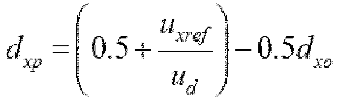

- The method according to claim 1, characterized in that the first, second and third set values of the x phase switch bridge arm do not equal to zero in at least one switch period, such that an output voltage of the x phase switch bridge arm includes the positive level, the negative level and the zero level in the at least one switch period; output voltages of at least two of the a, b and c phase switch bridge arms of the three-level circuit include the positive level, the negative level and the zero level in at least one switch period; when the modulating reference voltages of the a, b and c phase switch bridge arms are different, duty ratios of the zero level of the a, b and c phase switch bridge arms are different.
- The method according to claim 1, characterized in that when the three-level circuit is applied to a three-phase three wire electrical system, the method further comprises:step 14, when the absolute value of the first neutral point voltage is smaller than a second threshold value, injecting a zero sequence voltage, wherein the second threshold value is smaller than or equals to the first threshold value.
- A three-level circuit for converting a DC voltage into a three-phase AC voltage, wherein the three-level circuit comprises a capacitance bridge arm including upper and lower capacitors connected in series and three switch bridge arms electrically connected the capacitance bridge arm and being a, b and c phase switch bridge arms, respectively, wherein each of the a, b and c phase switch bridge arms includes at least four switch devices to output a positive level, a zero level, or a negative level, characterized in that the three-level circuit adopts the method according to claim 1.
- The three-level circuit according to claim 7, characterized in that the capacitance bridge arm includes a first DC input end, a neutral point level end and a second DC input end, wherein a first end of the upper capacitor is electrically connected to the first DC input end, a second end of the upper capacitor is electrically connected to the neutral point level end, a first end of the lower capacitor is electrically connected to the neutral point level end, and a second end of the lower capacitor is electrically connected to the second DC input end;
any one of the a, b and c phase switch bridge arms includes a first switch device, a second switch device, a third switch device, a fourth switch device, a first diode and a second diode; a first end of the first switch device is electrically connected to the first end of the upper capacitor, a second end of the first switch device is electrically connected to a first end of the second switch device, a second end of the second switch device is electrically connected to a first end of the third switch device, a second end of the third switch device is electrically connected to a first end of the fourth switch device, a second end of the fourth switch device is electrically connected to the second end of the lower capacitor; an anode of the first diode and a cathode of the second diode are electrically connected to the neutral point level end, a cathode of the first diode is electrically connected to the second end of the first switch device, and an anode of the second diode is electrically connected to the second end of the third switch device. - The three-level circuit according to claim 7, characterized in that the capacitance bridge arm includes a first DC input end, a neutral point level end and a second DC input end, wherein a first end of the upper capacitor is electrically connected to the first DC input end, a second end of the upper capacitor is electrically connected to the neutral point level end, a first end of the lower capacitor is electrically connected to the neutral point level end, and a second end of the lower capacitor is electrically connected to the second DC input end;
any one of the a, b and c phase switch bridge arms includes a first switch device, a second switch device, a third switch device and a fourth switch device; a first end of the first switch device is electrically connected to the first end of the upper capacitor, a second end of the first switch device is electrically connected to a first end of the fourth switch device and a second end of the third switch device, a first end of the second switch device is electrically connected to a first end of the third switch device, a second end of the second switch device is electrically connected to the neutral point level end, and a second end of the fourth switch device is electrically connected to the second end of the lower capacitor. - The three-level circuit according to claim 7, characterized in that the capacitance bridge arm includes a first DC input end, a neutral point level end and a second DC input end, wherein a first end of the upper capacitor is electrically connected to the first DC input end, a second end of the upper capacitor is electrically connected to the neutral point level end, a first end of the lower capacitor is electrically connected to the neutral point level end, and a second end of the lower capacitor is electrically connected to the second DC input end;
any one of the a, b and c phase switch bridge arms includes a first switch device, a second switch device, a third switch device, a fourth switch device, a fifth switch device and a sixth switch device; a first end of the first switch device is electrically connected to the first end of the upper capacitor, a second end of the first switch device is electrically connected to a first end of the second switch device and a first end of the fifth switch device, a second end of the second switch device is electrically connected to a first end of the third switch device, a second end of the third switch device is electrically connected to a first end of the fourth switch device and a second end of the sixth switch device, a second end of the fourth switch device is electrically connected to the second end of the lower capacitor, and a second end of the fifth switch device is electrically connected to a first end of the sixth switch device and the neutral point level end. - The three-level circuit according to claim 7, characterized in that the three-level circuit is electrically connected to a LC filter including at least three filter capacitors in star connection, wherein a neutral point of connection of the filter capacitors is electrically connected to a connection points of the upper and lower capacitors of the three-level circuit.
- A control method for balancing neutral point voltage of a neutral point clamped three-level circuit, wherein the three-level circuit is for converting a DC voltage into a three-phase AC voltage and comprises a capacitance bridge arm including upper and lower capacitors connected in series and three switch bridge arms electrically connected the capacitance bridge arm and being a, b and c phase switch bridge arms, respectively, each of which includes at least four switch devices to output a positive level, a zero level, or a negative level, characterized in that it comprises:step 21, obtaining a first neutral point voltage to represent a voltage difference between the upper and lower capacitors;step 22, adjusting a first set value of a duty ratio of the zero level of the x phase switch bridge arm, such that in a same switch period, when modulating reference voltages of the a, b and c phase switch bridge arms are different, duty ratios of the zero levels of the a, b and c phase switch bridge arms are different, wherein x represents the a, b and c phase switch bridge arms included in the three-level circuit;step 23, distributing a second set value for a duty ratio of the positive level of the x phase switch bridge arm and a third set value for a duty ratio of the negative level of the x phase switch bridge arm on the basis of the first set value, and modulating the switch devices of the x phase switch bridge arm according to the first, second and third set values, such that an output voltage of the x phase switch bridge arm includes positive, negative and zero levels in at least one switch period, and an absolute value of the first neutral point voltage is smaller than a first threshold value.
- The method according to claim 12, characterized in that the step 22 further includes:step 221, obtaining the maximum value d xomax within an adjustable range of the duty ratio of the zero level of the x phase switch bridge arm through
 step 222, presetting the first set value of the x phase switch bridge arm as the maximum value d xomax of the value range.
 - The method according to claim 12, characterized in that distributing the second set value for a duty ratio of the positive level of the x phase switch bridge arm and the third set value for a duty ratio of the negative level of the x phase switch bridge arm on the basis of the first set value in the step 23 includes:step 231, distributing the second set value dxp for a duty ratio of the positive level of the x phase switch bridge arm and the third set value dxn for a duty ratio of the negative level of the x phase switch bridge arm:


- The method according to claim 12, characterized in that when the three-level circuit is applied to a three-phase three wire electrical system, the method further comprises:step 24, when the absolute value of the first neutral point voltage is smaller than a second threshold value, injecting a zero sequence voltage, wherein the second threshold value is smaller than the first threshold value.
Applications Claiming Priority (1)
| Application Number | Priority Date | Filing Date | Title |
|---|---|---|---|
| CN201711294507.2A CN109905048B (en) | 2017-12-08 | 2017-12-08 | Neutral point voltage balance control method for three-level circuit |
Publications (2)
| Publication Number | Publication Date |
|---|---|
| EP3496257A1 true EP3496257A1 (en) | 2019-06-12 |
| EP3496257B1 EP3496257B1 (en) | 2022-01-05 |
Family
ID=64402115
Family Applications (1)
| Application Number | Title | Priority Date | Filing Date |
|---|---|---|---|
| EP18207313.0A Active EP3496257B1 (en) | 2017-12-08 | 2018-11-20 | Three-level circuit and control method for balancing neutral point voltage of the same |
Country Status (4)
| Country | Link |
|---|---|
| US (1) | US10374522B2 (en) |
| EP (1) | EP3496257B1 (en) |
| JP (1) | JP6609685B2 (en) |
| CN (1) | CN109905048B (en) |
Cited By (6)
| Publication number | Priority date | Publication date | Assignee | Title |
|---|---|---|---|---|
| CN112039362A (en) * | 2020-08-31 | 2020-12-04 | 深圳市盛弘电气股份有限公司 | Inversion control method and system, controller, inverter and readable storage medium |
| WO2021148617A1 (en) * | 2020-01-24 | 2021-07-29 | Bucher Hydraulics Ag | Power converter, charging post and vehicle |
| US20220329176A1 (en) * | 2021-04-13 | 2022-10-13 | Sungrow Power Supply Co., Ltd. | Inverter circuit control method and device thereof |
| CN115800328A (en) * | 2022-12-08 | 2023-03-14 | 成都天通电子科技有限公司 | Method, device and medium for controlling unbalance of three-phase four-leg full-bridge inverter |
| CN115811246A (en) * | 2022-12-02 | 2023-03-17 | 东北大学 | A three-level TNPC zero-voltage soft-switching inverter circuit and its modulation method |
| CN118054688A (en) * | 2024-04-12 | 2024-05-17 | 深圳力高新能技术有限公司 | Circuit and method for regulating and balancing positive and negative bus voltage |
Families Citing this family (39)
| Publication number | Priority date | Publication date | Assignee | Title |
|---|---|---|---|---|
| EP3467987B1 (en) * | 2017-10-06 | 2023-12-20 | General Electric Technology GmbH | Converter scheme |
| CN110146751B (en) * | 2019-07-01 | 2024-11-22 | 浙江华采科技有限公司 | Grid voltage detection circuit with zero-sequence voltage balance adjustment function |
| WO2021016382A1 (en) * | 2019-07-22 | 2021-01-28 | Brek Electronics Inc. | High density interleaved inverter |
| CN110445409B (en) * | 2019-07-30 | 2020-04-21 | 东北大学秦皇岛分校 | An Optimal Sequence Modulation Method for Converters with Midpoint Potential Control Capability |
| CN111371337B (en) * | 2020-04-09 | 2021-01-15 | 中南大学 | Neutral point potential balance control method of diode clamping type three-level inverter |
| CN111371338A (en) * | 2020-04-14 | 2020-07-03 | 上海宝准电源科技有限公司 | Neutral point potential balance control strategy of self-adaptive NPC three-level converter |
| JP7522865B2 (en) * | 2020-05-25 | 2024-07-25 | ヒタチ・エナジー・リミテッド | Auxiliary power device for a power grid including at least three groups of phase arms - Patent 7523633 |
| CN111814305B (en) * | 2020-06-03 | 2022-04-26 | 中国人民解放军海军工程大学 | Modeling Method for Uneven Capacitor Voltage of Pulse-jump NPC Cascade Inverter |
| CN112003490B (en) * | 2020-07-31 | 2021-06-04 | 北京金风科创风电设备有限公司 | Power components of three-level converters and three-level converters |
| CN111953223B (en) * | 2020-08-12 | 2022-10-18 | 合肥工业大学 | A method of neutral point voltage balance of three-phase four-wire three-level converter |
| CN112202353B (en) * | 2020-08-25 | 2022-07-01 | 远景能源有限公司 | Doubly-fed frequency converter and its modulation method |
| CN112271949B (en) * | 2020-11-12 | 2025-07-25 | 江西清华泰豪三波电机有限公司 | Three-phase four-bridge arm midpoint balance control device and power supply equipment |
| US11791710B2 (en) * | 2021-02-23 | 2023-10-17 | Apple Inc. | Switching sequence controlled current steering for stacked half bridge converters |
| CN114583989B (en) * | 2021-03-22 | 2023-09-22 | 上海正泰电源系统有限公司 | Three-level inverter modulation mode switching method, device, equipment and storage medium |
| CN113410829B (en) * | 2021-05-08 | 2023-05-16 | 新天绿色能源股份有限公司 | True bipolar direct current micro-grid busbar voltage balancing device and control method thereof |
| US11552551B2 (en) * | 2021-05-25 | 2023-01-10 | City University Of Hong Kong | Method of control of a system comprising a single-phase three-level T type quasi-Z source inverter connected to an LC filter which is in turn connected to a load |
| CN113258752B (en) * | 2021-06-07 | 2021-10-01 | 深圳市永联科技股份有限公司 | A kind of dynamic control method, system and power supply module of circuit signal |
| CN113541170B (en) * | 2021-06-16 | 2023-11-24 | 武汉理工大学 | Fuel cell emergency power supply grid-connected inverter control method and system |
| CN113381628B (en) * | 2021-07-27 | 2022-08-30 | 盾石磁能科技有限责任公司 | Midpoint balance control method of flywheel energy storage motor driving circuit in discharging process |
| CN114172401B (en) * | 2021-11-12 | 2023-08-29 | 合肥工业大学 | NPC three-level inverter multi-class fault diagnosis method based on reduced order observer |
| CN114337313B (en) * | 2021-11-12 | 2024-05-14 | 中车永济电机有限公司 | Integrated power supply and multichannel auxiliary transmission system |
| CN114675212B (en) * | 2022-03-25 | 2024-06-04 | 江苏方天电力技术有限公司 | Method for studying and judging abnormal connection of neutral point of distribution transformer |
| DE112022006901T5 (en) * | 2022-03-25 | 2025-01-09 | Tmeic Corporation | ENERGY CONVERSION DEVICE |
| CN114665734B (en) * | 2022-04-29 | 2025-05-20 | 深圳市英威腾电气股份有限公司 | Control method and system for balancing midpoint voltage and related components |
| CN114640264B (en) * | 2022-05-20 | 2022-09-02 | 锦浪科技股份有限公司 | Three-phase four-wire three-level circuit bus midpoint current control method and device |
| CN115528940B (en) * | 2022-09-21 | 2025-07-18 | 易事特储能科技有限公司 | Neutral point balance and circulation control method and system for staggered parallel three-level converter |
| CN115642825A (en) * | 2022-11-02 | 2023-01-24 | 江苏科曜能源科技有限公司 | Three-phase five-level PWM inverter and application |
| CN116191917A (en) * | 2022-11-21 | 2023-05-30 | 国电南瑞科技股份有限公司 | A three-level DC transformer midpoint potential control loop, method and system |
| CN118199434A (en) * | 2022-12-12 | 2024-06-14 | 台达电子企业管理(上海)有限公司 | Power conversion device and control method thereof |
| CN115982999B (en) * | 2022-12-29 | 2025-07-18 | 中车永济电机有限公司 | Loss calculation method for NPC three-level converter |
| CN116032144B (en) * | 2023-03-29 | 2023-06-16 | 成都希望电子研究所有限公司 | Synchronous overmodulation algorithm for cooperative control of harmonic wave and midpoint potential |
| CN116526883A (en) * | 2023-05-16 | 2023-08-01 | 江苏科曜能源科技有限公司 | Three-phase three-level four-bridge arm energy storage inverter and inverter system |
| US20250141369A1 (en) * | 2023-10-27 | 2025-05-01 | Infineon Technologies Ag | Multi-phase inverter |
| CN117394708B (en) * | 2023-12-13 | 2024-02-20 | 四川大学 | Current-mode PWM rectifier control system and method suitable for input unbalance |
| CN117937965B (en) * | 2024-03-25 | 2024-06-04 | 西安图为电气技术有限公司 | Neutral point potential balance control method, electronic device, and computer-readable storage medium |
| CN118300115B (en) * | 2024-04-22 | 2024-11-19 | 兴储世纪科技(深圳)有限公司 | A DQ axis decoupling NPC midpoint voltage control method and system |
| CN118381365B (en) * | 2024-06-24 | 2024-08-23 | 西安图为电气技术有限公司 | Three-level inverter modulation method, electronic device, and computer-readable storage medium |
| CN118868654B (en) | 2024-09-25 | 2025-01-14 | 上海思格源智能科技有限公司 | Voltage modulation method and three-level inverter |
| CN119742801B (en) * | 2025-03-04 | 2025-06-24 | 苏州腾冉电气设备股份有限公司 | Direct-current neutral line stable control method and control system for NPC three-level three-phase four-wire system PCS |
Citations (2)
| Publication number | Priority date | Publication date | Assignee | Title |
|---|---|---|---|---|
| KR20160101034A (en) * | 2013-12-18 | 2016-08-24 | 오티스 엘리베이터 컴파니 | Multilevel drive half dc bus power supplies |
| CN107317500A (en) * | 2017-08-28 | 2017-11-03 | 清华大学 | A kind of bus capacitor voltage balancing control method of the level converter of neutral point clamp four |
Family Cites Families (10)
| Publication number | Priority date | Publication date | Assignee | Title |
|---|---|---|---|---|
| JP2884880B2 (en) * | 1992-02-12 | 1999-04-19 | 株式会社日立製作所 | Control device for power converter |
| AU651034B2 (en) * | 1992-04-24 | 1994-07-07 | Hitachi Limited | Power converter for converting DC voltage into AC phase voltage having three levels of positive, zero and negative voltage |
| JP2888104B2 (en) * | 1993-09-01 | 1999-05-10 | 株式会社日立製作所 | Power converter |
| JP3856689B2 (en) * | 2001-11-30 | 2006-12-13 | 東芝三菱電機産業システム株式会社 | Neutral point clamp type power converter controller |
| JP5822732B2 (en) * | 2012-01-11 | 2015-11-24 | 東芝三菱電機産業システム株式会社 | 3-level power converter |
| US20150003134A1 (en) * | 2012-02-16 | 2015-01-01 | Alstom Technology Ltd | Modular multilevel converter using asymmetry |
| JP5664819B1 (en) * | 2014-09-16 | 2015-02-04 | 富士電機株式会社 | Uninterruptible power supply controller |
| JP6131360B1 (en) * | 2016-03-28 | 2017-05-17 | 三菱電機エンジニアリング株式会社 | Power converter |
| CN206117535U (en) | 2016-10-14 | 2017-04-19 | 华南理工大学 | To independent average current control circuit of three -phase of three -sphase four -wire system VIENNA rectifier |
| CN109391161A (en) * | 2017-08-10 | 2019-02-26 | 台达电子企业管理(上海)有限公司 | Technics of Power Electronic Conversion unit and system |
-
2017
- 2017-12-08 CN CN201711294507.2A patent/CN109905048B/en active Active
-
2018
- 2018-11-07 US US16/183,715 patent/US10374522B2/en active Active
- 2018-11-15 JP JP2018214973A patent/JP6609685B2/en active Active
- 2018-11-20 EP EP18207313.0A patent/EP3496257B1/en active Active
Patent Citations (3)
| Publication number | Priority date | Publication date | Assignee | Title |
|---|---|---|---|---|
| KR20160101034A (en) * | 2013-12-18 | 2016-08-24 | 오티스 엘리베이터 컴파니 | Multilevel drive half dc bus power supplies |
| CN107317500A (en) * | 2017-08-28 | 2017-11-03 | 清华大学 | A kind of bus capacitor voltage balancing control method of the level converter of neutral point clamp four |
| US20190068080A1 (en) * | 2017-08-28 | 2019-02-28 | Tsinghua University | Method and device for voltage balancing of dc bus capacitors of neutral-point clamped four-level inverter |
Cited By (9)
| Publication number | Priority date | Publication date | Assignee | Title |
|---|---|---|---|---|
| WO2021148617A1 (en) * | 2020-01-24 | 2021-07-29 | Bucher Hydraulics Ag | Power converter, charging post and vehicle |
| US12451795B2 (en) | 2020-01-24 | 2025-10-21 | Bucher Hydraulics Ag | Power converter, charging post and vehicle |
| CN112039362A (en) * | 2020-08-31 | 2020-12-04 | 深圳市盛弘电气股份有限公司 | Inversion control method and system, controller, inverter and readable storage medium |
| US20220329176A1 (en) * | 2021-04-13 | 2022-10-13 | Sungrow Power Supply Co., Ltd. | Inverter circuit control method and device thereof |
| EP4075659A1 (en) * | 2021-04-13 | 2022-10-19 | Sungrow Power Supply Co., Ltd. | Inverter circuit control method and device thereof |
| US11722072B2 (en) | 2021-04-13 | 2023-08-08 | Sungrow Power Supply Co., Ltd. | Inverter circuit control method and device thereof |
| CN115811246A (en) * | 2022-12-02 | 2023-03-17 | 东北大学 | A three-level TNPC zero-voltage soft-switching inverter circuit and its modulation method |
| CN115800328A (en) * | 2022-12-08 | 2023-03-14 | 成都天通电子科技有限公司 | Method, device and medium for controlling unbalance of three-phase four-leg full-bridge inverter |
| CN118054688A (en) * | 2024-04-12 | 2024-05-17 | 深圳力高新能技术有限公司 | Circuit and method for regulating and balancing positive and negative bus voltage |
Also Published As
| Publication number | Publication date |
|---|---|
| CN109905048A (en) | 2019-06-18 |
| US10374522B2 (en) | 2019-08-06 |
| JP2019106874A (en) | 2019-06-27 |
| JP6609685B2 (en) | 2019-11-20 |
| EP3496257B1 (en) | 2022-01-05 |
| CN109905048B (en) | 2021-01-26 |
| US20190181774A1 (en) | 2019-06-13 |
Similar Documents
| Publication | Publication Date | Title |
|---|---|---|
| EP3496257B1 (en) | Three-level circuit and control method for balancing neutral point voltage of the same | |
| CN109787498B (en) | Method and system for midpoint balance control of full power factor range three-level converters | |
| CN107317500B (en) | A bus capacitor voltage balance control method for a midpoint clamped four-level converter | |
| CA3005146C (en) | Medium voltage transformerless multilevel converter and method for controlling a medium voltage transformerless multilevel converter | |
| US7518893B2 (en) | Method for operation of a converter circuit, as well as an apparatus for carrying out the method | |
| Chebabhi et al. | A new balancing three level three dimensional space vector modulation strategy for three level neutral point clamped four leg inverter based shunt active power filter controlling by nonlinear back stepping controllers | |
| EP2876793A1 (en) | Method and arrangement for reducing current stress in intermediate circuit of three-level inverter | |
| CN105071679A (en) | Five-level self-balanced inverter based on bridge switched capacitor module | |
| CN107947599A (en) | Electronic power convertor | |
| CN105024569A (en) | Branched structure modular multilevel converter suitable for low modulation ratio application | |
| EP3506474A1 (en) | Single-phase converter control method and apparatus | |
| CN102684533A (en) | Neutral point voltage control method for neutral point clamped (NPC) type three-level inverter based on carrier amplitude shift | |
| CN115800790A (en) | Three-level converter parallel system control method considering both circulating current suppression and midpoint balance | |
| Silva et al. | Analysis and proposal of capacitor voltage control for an asymmetric cascaded inverter | |
| Anuradha et al. | Neutral point voltage level stabilization and DC link capacitors voltage balance in neutral point clamped multilevel inverters | |
| CN106941324A (en) | The DC voltage balance control method of neutral point clamp type three-level voltage source current transformer | |
| CN109546877A (en) | A kind of static synchronous compensating device | |
| CN104753378A (en) | Three-level inverter midpoint potential balance control method | |
| Pribadi et al. | A novel six-level inverter topology with capacitor voltage self-balancing | |
| CN110504853A (en) | Improved circulation control method based on flexible direct current transmission | |
| Reddy et al. | Simulation and Comparison of Twenty Five Level Diode Clamped & Cascaded H-Bridge Multilevel Inverter | |
| Divan et al. | Control of multilevel direct ac converters | |
| Farhadi et al. | Predictive control of neutral-point clamped indirect matrix converter | |
| Sundararajan et al. | Comparison of current controllers for a five-level cascaded H-bridge multilevel inverter | |
| EP2725696A1 (en) | Power conversion device and device for controlling same |
Legal Events
| Date | Code | Title | Description |
|---|---|---|---|
| PUAI | Public reference made under article 153(3) epc to a published international application that has entered the european phase |
Free format text: ORIGINAL CODE: 0009012 |
|
| STAA | Information on the status of an ep patent application or granted ep patent |
Free format text: STATUS: REQUEST FOR EXAMINATION WAS MADE |
|
| 17P | Request for examination filed |
Effective date: 20181120 |
|
| AK | Designated contracting states |
Kind code of ref document: A1 Designated state(s): AL AT BE BG CH CY CZ DE DK EE ES FI FR GB GR HR HU IE IS IT LI LT LU LV MC MK MT NL NO PL PT RO RS SE SI SK SM TR |
|
| AX | Request for extension of the european patent |
Extension state: BA ME |
|
| RBV | Designated contracting states (corrected) |
Designated state(s): AL AT BE BG CH CY CZ DE DK EE ES FI FR GB GR HR HU IE IS IT LI LT LU LV MC MK MT NL NO PL PT RO RS SE SI SK SM TR |
|
| STAA | Information on the status of an ep patent application or granted ep patent |
Free format text: STATUS: EXAMINATION IS IN PROGRESS |
|
| 17Q | First examination report despatched |
Effective date: 20200323 |
|
| GRAP | Despatch of communication of intention to grant a patent |
Free format text: ORIGINAL CODE: EPIDOSNIGR1 |
|
| STAA | Information on the status of an ep patent application or granted ep patent |
Free format text: STATUS: GRANT OF PATENT IS INTENDED |
|
| RIC1 | Information provided on ipc code assigned before grant |
Ipc: H02M 7/487 20070101AFI20210604BHEP Ipc: H02M 7/5395 20060101ALI20210604BHEP Ipc: H02M 7/483 20070101ALI20210604BHEP |
|
| INTG | Intention to grant announced |
Effective date: 20210625 |
|
| GRAS | Grant fee paid |
Free format text: ORIGINAL CODE: EPIDOSNIGR3 |
|
| GRAA | (expected) grant |
Free format text: ORIGINAL CODE: 0009210 |
|
| STAA | Information on the status of an ep patent application or granted ep patent |
Free format text: STATUS: THE PATENT HAS BEEN GRANTED |
|
| AK | Designated contracting states |
Kind code of ref document: B1 Designated state(s): AL AT BE BG CH CY CZ DE DK EE ES FI FR GB GR HR HU IE IS IT LI LT LU LV MC MK MT NL NO PL PT RO RS SE SI SK SM TR |
|
| REG | Reference to a national code |
Ref country code: GB Ref legal event code: FG4D |
|
| REG | Reference to a national code |
Ref country code: CH Ref legal event code: EP |
|
| REG | Reference to a national code |
Ref country code: AT Ref legal event code: REF Ref document number: 1461482 Country of ref document: AT Kind code of ref document: T Effective date: 20220115 |
|
| REG | Reference to a national code |
Ref country code: DE Ref legal event code: R096 Ref document number: 602018029060 Country of ref document: DE |
|
| REG | Reference to a national code |
Ref country code: IE Ref legal event code: FG4D |
|
| REG | Reference to a national code |
Ref country code: NL Ref legal event code: FP |
|
| REG | Reference to a national code |
Ref country code: LT Ref legal event code: MG9D |
|
| REG | Reference to a national code |
Ref country code: AT Ref legal event code: MK05 Ref document number: 1461482 Country of ref document: AT Kind code of ref document: T Effective date: 20220105 |
|
| PG25 | Lapsed in a contracting state [announced via postgrant information from national office to epo] |
Ref country code: SE Free format text: LAPSE BECAUSE OF FAILURE TO SUBMIT A TRANSLATION OF THE DESCRIPTION OR TO PAY THE FEE WITHIN THE PRESCRIBED TIME-LIMIT Effective date: 20220105 Ref country code: RS Free format text: LAPSE BECAUSE OF FAILURE TO SUBMIT A TRANSLATION OF THE DESCRIPTION OR TO PAY THE FEE WITHIN THE PRESCRIBED TIME-LIMIT Effective date: 20220105 Ref country code: PT Free format text: LAPSE BECAUSE OF FAILURE TO SUBMIT A TRANSLATION OF THE DESCRIPTION OR TO PAY THE FEE WITHIN THE PRESCRIBED TIME-LIMIT Effective date: 20220505 Ref country code: NO Free format text: LAPSE BECAUSE OF FAILURE TO SUBMIT A TRANSLATION OF THE DESCRIPTION OR TO PAY THE FEE WITHIN THE PRESCRIBED TIME-LIMIT Effective date: 20220405 Ref country code: LT Free format text: LAPSE BECAUSE OF FAILURE TO SUBMIT A TRANSLATION OF THE DESCRIPTION OR TO PAY THE FEE WITHIN THE PRESCRIBED TIME-LIMIT Effective date: 20220105 Ref country code: HR Free format text: LAPSE BECAUSE OF FAILURE TO SUBMIT A TRANSLATION OF THE DESCRIPTION OR TO PAY THE FEE WITHIN THE PRESCRIBED TIME-LIMIT Effective date: 20220105 Ref country code: ES Free format text: LAPSE BECAUSE OF FAILURE TO SUBMIT A TRANSLATION OF THE DESCRIPTION OR TO PAY THE FEE WITHIN THE PRESCRIBED TIME-LIMIT Effective date: 20220105 Ref country code: BG Free format text: LAPSE BECAUSE OF FAILURE TO SUBMIT A TRANSLATION OF THE DESCRIPTION OR TO PAY THE FEE WITHIN THE PRESCRIBED TIME-LIMIT Effective date: 20220405 |
|
| PG25 | Lapsed in a contracting state [announced via postgrant information from national office to epo] |
Ref country code: PL Free format text: LAPSE BECAUSE OF FAILURE TO SUBMIT A TRANSLATION OF THE DESCRIPTION OR TO PAY THE FEE WITHIN THE PRESCRIBED TIME-LIMIT Effective date: 20220105 Ref country code: LV Free format text: LAPSE BECAUSE OF FAILURE TO SUBMIT A TRANSLATION OF THE DESCRIPTION OR TO PAY THE FEE WITHIN THE PRESCRIBED TIME-LIMIT Effective date: 20220105 Ref country code: GR Free format text: LAPSE BECAUSE OF FAILURE TO SUBMIT A TRANSLATION OF THE DESCRIPTION OR TO PAY THE FEE WITHIN THE PRESCRIBED TIME-LIMIT Effective date: 20220406 Ref country code: FI Free format text: LAPSE BECAUSE OF FAILURE TO SUBMIT A TRANSLATION OF THE DESCRIPTION OR TO PAY THE FEE WITHIN THE PRESCRIBED TIME-LIMIT Effective date: 20220105 Ref country code: AT Free format text: LAPSE BECAUSE OF FAILURE TO SUBMIT A TRANSLATION OF THE DESCRIPTION OR TO PAY THE FEE WITHIN THE PRESCRIBED TIME-LIMIT Effective date: 20220105 |
|
| PG25 | Lapsed in a contracting state [announced via postgrant information from national office to epo] |
Ref country code: IS Free format text: LAPSE BECAUSE OF FAILURE TO SUBMIT A TRANSLATION OF THE DESCRIPTION OR TO PAY THE FEE WITHIN THE PRESCRIBED TIME-LIMIT Effective date: 20220505 |
|
| REG | Reference to a national code |
Ref country code: DE Ref legal event code: R097 Ref document number: 602018029060 Country of ref document: DE |
|
| PG25 | Lapsed in a contracting state [announced via postgrant information from national office to epo] |
Ref country code: SM Free format text: LAPSE BECAUSE OF FAILURE TO SUBMIT A TRANSLATION OF THE DESCRIPTION OR TO PAY THE FEE WITHIN THE PRESCRIBED TIME-LIMIT Effective date: 20220105 Ref country code: SK Free format text: LAPSE BECAUSE OF FAILURE TO SUBMIT A TRANSLATION OF THE DESCRIPTION OR TO PAY THE FEE WITHIN THE PRESCRIBED TIME-LIMIT Effective date: 20220105 Ref country code: RO Free format text: LAPSE BECAUSE OF FAILURE TO SUBMIT A TRANSLATION OF THE DESCRIPTION OR TO PAY THE FEE WITHIN THE PRESCRIBED TIME-LIMIT Effective date: 20220105 Ref country code: EE Free format text: LAPSE BECAUSE OF FAILURE TO SUBMIT A TRANSLATION OF THE DESCRIPTION OR TO PAY THE FEE WITHIN THE PRESCRIBED TIME-LIMIT Effective date: 20220105 Ref country code: DK Free format text: LAPSE BECAUSE OF FAILURE TO SUBMIT A TRANSLATION OF THE DESCRIPTION OR TO PAY THE FEE WITHIN THE PRESCRIBED TIME-LIMIT Effective date: 20220105 Ref country code: CZ Free format text: LAPSE BECAUSE OF FAILURE TO SUBMIT A TRANSLATION OF THE DESCRIPTION OR TO PAY THE FEE WITHIN THE PRESCRIBED TIME-LIMIT Effective date: 20220105 |
|
| PLBE | No opposition filed within time limit |
Free format text: ORIGINAL CODE: 0009261 |
|
| STAA | Information on the status of an ep patent application or granted ep patent |
Free format text: STATUS: NO OPPOSITION FILED WITHIN TIME LIMIT |
|
| PG25 | Lapsed in a contracting state [announced via postgrant information from national office to epo] |
Ref country code: AL Free format text: LAPSE BECAUSE OF FAILURE TO SUBMIT A TRANSLATION OF THE DESCRIPTION OR TO PAY THE FEE WITHIN THE PRESCRIBED TIME-LIMIT Effective date: 20220105 |
|
| 26N | No opposition filed |
Effective date: 20221006 |
|
| PG25 | Lapsed in a contracting state [announced via postgrant information from national office to epo] |
Ref country code: SI Free format text: LAPSE BECAUSE OF FAILURE TO SUBMIT A TRANSLATION OF THE DESCRIPTION OR TO PAY THE FEE WITHIN THE PRESCRIBED TIME-LIMIT Effective date: 20220105 |
|
| PG25 | Lapsed in a contracting state [announced via postgrant information from national office to epo] |
Ref country code: MC Free format text: LAPSE BECAUSE OF FAILURE TO SUBMIT A TRANSLATION OF THE DESCRIPTION OR TO PAY THE FEE WITHIN THE PRESCRIBED TIME-LIMIT Effective date: 20220105 |
|
| REG | Reference to a national code |
Ref country code: CH Ref legal event code: PL |
|
| GBPC | Gb: european patent ceased through non-payment of renewal fee |
Effective date: 20221120 |
|
| REG | Reference to a national code |
Ref country code: BE Ref legal event code: MM Effective date: 20221130 |
|
| PG25 | Lapsed in a contracting state [announced via postgrant information from national office to epo] |
Ref country code: LI Free format text: LAPSE BECAUSE OF NON-PAYMENT OF DUE FEES Effective date: 20221130 Ref country code: IT Free format text: LAPSE BECAUSE OF FAILURE TO SUBMIT A TRANSLATION OF THE DESCRIPTION OR TO PAY THE FEE WITHIN THE PRESCRIBED TIME-LIMIT Effective date: 20220105 Ref country code: CH Free format text: LAPSE BECAUSE OF NON-PAYMENT OF DUE FEES Effective date: 20221130 |
|
| PG25 | Lapsed in a contracting state [announced via postgrant information from national office to epo] |
Ref country code: LU Free format text: LAPSE BECAUSE OF NON-PAYMENT OF DUE FEES Effective date: 20221120 |
|
| PG25 | Lapsed in a contracting state [announced via postgrant information from national office to epo] |
Ref country code: IE Free format text: LAPSE BECAUSE OF NON-PAYMENT OF DUE FEES Effective date: 20221120 Ref country code: GB Free format text: LAPSE BECAUSE OF NON-PAYMENT OF DUE FEES Effective date: 20221120 |
|
| PG25 | Lapsed in a contracting state [announced via postgrant information from national office to epo] |
Ref country code: FR Free format text: LAPSE BECAUSE OF NON-PAYMENT OF DUE FEES Effective date: 20221130 Ref country code: BE Free format text: LAPSE BECAUSE OF NON-PAYMENT OF DUE FEES Effective date: 20221130 |
|
| PG25 | Lapsed in a contracting state [announced via postgrant information from national office to epo] |
Ref country code: HU Free format text: LAPSE BECAUSE OF FAILURE TO SUBMIT A TRANSLATION OF THE DESCRIPTION OR TO PAY THE FEE WITHIN THE PRESCRIBED TIME-LIMIT; INVALID AB INITIO Effective date: 20181120 |
|
| PG25 | Lapsed in a contracting state [announced via postgrant information from national office to epo] |
Ref country code: CY Free format text: LAPSE BECAUSE OF FAILURE TO SUBMIT A TRANSLATION OF THE DESCRIPTION OR TO PAY THE FEE WITHIN THE PRESCRIBED TIME-LIMIT Effective date: 20220105 |
|
| PG25 | Lapsed in a contracting state [announced via postgrant information from national office to epo] |
Ref country code: MK Free format text: LAPSE BECAUSE OF FAILURE TO SUBMIT A TRANSLATION OF THE DESCRIPTION OR TO PAY THE FEE WITHIN THE PRESCRIBED TIME-LIMIT Effective date: 20220105 |
|
| PG25 | Lapsed in a contracting state [announced via postgrant information from national office to epo] |
Ref country code: MT Free format text: LAPSE BECAUSE OF FAILURE TO SUBMIT A TRANSLATION OF THE DESCRIPTION OR TO PAY THE FEE WITHIN THE PRESCRIBED TIME-LIMIT Effective date: 20220105 |
|
| PGFP | Annual fee paid to national office [announced via postgrant information from national office to epo] |
Ref country code: NL Payment date: 20251003 Year of fee payment: 8 |
|
| PG25 | Lapsed in a contracting state [announced via postgrant information from national office to epo] |
Ref country code: TR Free format text: LAPSE BECAUSE OF FAILURE TO SUBMIT A TRANSLATION OF THE DESCRIPTION OR TO PAY THE FEE WITHIN THE PRESCRIBED TIME-LIMIT Effective date: 20220105 |
|
| PGFP | Annual fee paid to national office [announced via postgrant information from national office to epo] |
Ref country code: DE Payment date: 20250923 Year of fee payment: 8 |