EP3496223A1 - Control device - Google Patents
Control device Download PDFInfo
- Publication number
- EP3496223A1 EP3496223A1 EP17836649.8A EP17836649A EP3496223A1 EP 3496223 A1 EP3496223 A1 EP 3496223A1 EP 17836649 A EP17836649 A EP 17836649A EP 3496223 A1 EP3496223 A1 EP 3496223A1
- Authority
- EP
- European Patent Office
- Prior art keywords
- ecu
- control device
- case
- body section
- lcr
- Prior art date
- Legal status (The legal status is an assumption and is not a legal conclusion. Google has not performed a legal analysis and makes no representation as to the accuracy of the status listed.)
- Granted
Links
Images

Classifications
-
- B—PERFORMING OPERATIONS; TRANSPORTING
- B60—VEHICLES IN GENERAL
- B60R—VEHICLES, VEHICLE FITTINGS, OR VEHICLE PARTS, NOT OTHERWISE PROVIDED FOR
- B60R16/00—Electric or fluid circuits specially adapted for vehicles and not otherwise provided for; Arrangement of elements of electric or fluid circuits specially adapted for vehicles and not otherwise provided for
- B60R16/02—Electric or fluid circuits specially adapted for vehicles and not otherwise provided for; Arrangement of elements of electric or fluid circuits specially adapted for vehicles and not otherwise provided for electric constitutive elements
- B60R16/023—Electric or fluid circuits specially adapted for vehicles and not otherwise provided for; Arrangement of elements of electric or fluid circuits specially adapted for vehicles and not otherwise provided for electric constitutive elements for transmission of signals between vehicle parts or subsystems
- B60R16/0239—Electronic boxes
-
- B—PERFORMING OPERATIONS; TRANSPORTING
- B60—VEHICLES IN GENERAL
- B60R—VEHICLES, VEHICLE FITTINGS, OR VEHICLE PARTS, NOT OTHERWISE PROVIDED FOR
- B60R16/00—Electric or fluid circuits specially adapted for vehicles and not otherwise provided for; Arrangement of elements of electric or fluid circuits specially adapted for vehicles and not otherwise provided for
- B60R16/02—Electric or fluid circuits specially adapted for vehicles and not otherwise provided for; Arrangement of elements of electric or fluid circuits specially adapted for vehicles and not otherwise provided for electric constitutive elements
-
- H—ELECTRICITY
- H02—GENERATION; CONVERSION OR DISTRIBUTION OF ELECTRIC POWER
- H02G—INSTALLATION OF ELECTRIC CABLES OR LINES, OR OF COMBINED OPTICAL AND ELECTRIC CABLES OR LINES
- H02G3/00—Installations of electric cables or lines or protective tubing therefor in or on buildings, equivalent structures or vehicles
- H02G3/02—Details
- H02G3/08—Distribution boxes; Connection or junction boxes
- H02G3/16—Distribution boxes; Connection or junction boxes structurally associated with support for line-connecting terminals within the box
Definitions
- the present invention relates to a control device that is preferably applied to an engine control unit (ECU) mounted on an automobile, for example.
- ECU engine control unit
- an ECU has been mounted as a control device that executes basic engine control such as ignition timing and fuel injection.
- basic engine control such as ignition timing and fuel injection.
- an ECU that has functions of executing automatic transmission (AT) control and control related to a drive system, a brake system, a steering system, and the like, in addition to the engine control, has been available (for example, see PTL 1) .
- AT automatic transmission
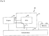
- an ECU 20 of this type is configured that an ECU body section 22 is accommodated in an ECU case 21 formed from a conductive material such as a metal material, and the ECU body section 22 is connected to an engine 23 as a control target via a wire harness 24.
- the engine 23 and the ECU case 21 are each connected to a ground via a vehicle body 25.
- the applicant of the present application conducted an electrical stress test, in which noise was injected into the wire harness 24, on the ECU 20 with such a configuration, and it was acknowledged that a loop current I 11 at a particular frequency was generated in the ECU 20, the loop current I 11 repeatedly flowing from the ECU body section 22 and flowing back to the ECU body section 22 through the coupling capacitors 26, the ECU case 21, and the coupling capacitors 26.
- the frequency of such a loop current I 11 depends on a shape of the ECU 20 and the like.
- the present invention has been made in consideration of the points that have been described so far and therefore proposes a control device capable of realizing high reliability by suppressing occurrence of an erroneous operation.
- an LCR circuit that electrically connects the control device body and the case is provided.
- this loop current can be attenuated by the LCR circuit.
- the highly reliable control device can be realized.
- the reference sign 1 denotes an entire ECU 1 in a first embodiment.
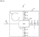
- This ECU 1 is a control device that is mounted on an automobile or the like instead of the conventional ECU 20 that has been described above with reference to Fig. 3 , and the ECU body section 22 and the ECU case 21 are electrically connected by one or plural LCR series circuits 5. In addition, it is configured that insulation between the ECU body section 22 and the ECU case 21 is provided.
- the LCR series circuit 5 is configured to include a resistor 2, a coil 3, and a capacitor 4 that are connected in series in such an order.
- a resistance value of the resistor 2 is set as R[ ⁇ ]
- self-inductance of the coil 3 is set as L[H]
- capacity of the capacitor 4 is set as C[F]
- each of the resistance value R of the resistor 2, the self-inductance L of the coil 3, and the capacity C of the capacitor 4 is selected such that the resistance value Z 1 becomes a maximum value.
- the at least one LCR series circuit 5 is arranged near the wire harness 24 in the ECU case 21. Accordingly, in this ECU 1, the loop current I 1 , which is generated by the noise flowing into the ECU 1 via the wire harness 24, can promptly be attenuated by the LCR series circuit 5 disposed near the wire harness 24.
- the LCR series circuits 5 are arranged in an equally distributed manner in the ECU case 21. In this way, in this ECU 1, the loop current I 1 , which is generated in the entire ECU 1, can efficiently be attenuated by each of the LCR series circuits 5.
- the ECU 1 of this embodiment even when the loop current I 1 is generated by the noise flowing thereinto via the wire harness 24, the loop current I 1 can promptly be attenuated by the LCR series circuit 5. Therefore, an erroneous operation of the ECU body section 22 and the like can effectively be prevented. In this way, the highly reliable ECU can be realized.
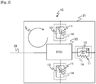
- the reference sign 10 denotes an entire ECU in a second embodiment.
- This ECU 10 is configured in a similar manner to the ECU 1 in the first embodiment except for a point that the ECU body section 22 and the ECU case 21 are electrically connected by one or plural LCR parallel circuits 14 instead of the LCR series circuit 5.
- the LCR parallel circuit 14 is configured to include a resistor 11, a coil 12, and a capacitor 13 that are connected in parallel.
- the resistance value of the resistor is set as R[ ⁇ ]
- the self-inductance of the coil is set as L[H]
- the capacity of the capacitor is set as C[F]
- each of the resistance value R of the resistor 11, the self-inductance L of the coil 12, and the capacity C of the capacitor 13 is selected such that the resistance value Z 2 becomes a maximum value.
- the resistance value Z 2 is acquired from the formula (3) by setting a frequency of the loop current I 2 , which is generated in the ECU 10 when the noise is injected into the wire harness 24, as f and assigning ⁇ , which is defined by the above-described formula (2), to the formula (3).
- the ECU 10 of this embodiment similar to the first embodiment, even when the loop current I 2 is generated by the noise flowing thereinto via the wire harness 24, the loop current I 2 can promptly be attenuated by the LCR parallel circuit 14. Therefore, the erroneous operation of the ECU body section 22 and the like can effectively be prevented. In this way, the highly reliable ECU can be realized.
Landscapes
- Engineering & Computer Science (AREA)
- Mechanical Engineering (AREA)
- Architecture (AREA)
- Civil Engineering (AREA)
- Structural Engineering (AREA)
- Ignition Installations For Internal Combustion Engines (AREA)
- Emergency Protection Circuit Devices (AREA)
- Direct Current Feeding And Distribution (AREA)
- Connection Or Junction Boxes (AREA)
- Shielding Devices Or Components To Electric Or Magnetic Fields (AREA)
Abstract
Description
- The present invention relates to a control device that is preferably applied to an engine control unit (ECU) mounted on an automobile, for example.
- Conventionally, on an automobile, an ECU has been mounted as a control device that executes basic engine control such as ignition timing and fuel injection. In recent years, an ECU that has functions of executing automatic transmission (AT) control and control related to a drive system, a brake system, a steering system, and the like, in addition to the engine control, has been available (for example, see PTL 1) .
- As illustrated in
Fig. 3 , anECU 20 of this type is configured that anECU body section 22 is accommodated in anECU case 21 formed from a conductive material such as a metal material, and theECU body section 22 is connected to anengine 23 as a control target via awire harness 24. In addition, theengine 23 and theECU case 21 are each connected to a ground via avehicle body 25. - Here, it has been known that, even when the
engine 23 and theECU case 21 are each electrically connected to thevehicle body 25, an electric potential of theengine 23 and an electric potential of thevehicle body 25 do not always match each other. In the case where the electric potential of theengine 23 is higher than the electric potential of thevehicle body 25, an unexpected current I10 possibly flows from theengine 23 into theECU body section 22 in theECU 20 via thewire harness 24. - For this reason, in the
ECU 20, electrical insulation between theECU body section 22 and theECU case 21 is provided, which prevents the unexpected current I10 from flowing into theECU body section 22. - PTL 1:
JP-A-2015-182711 - By the way, of the
ECUs 20, such anECU 20 has been available that theECU body section 22 and theECU case 21 are electrically connected bycoupling capacitors 26 as illustrated inFig. 4 (A) , so as to release static electricity that is applied to theECU body section 22 in an electrostatic test to theECU case 21, the electrostatic test being conducted to examine resistance of theECU body section 22 to the static electricity. - As illustrated in
Fig. 4 (B) , the applicant of the present application conducted an electrical stress test, in which noise was injected into thewire harness 24, on theECU 20 with such a configuration, and it was acknowledged that a loop current I11 at a particular frequency was generated in theECU 20, the loop current I11 repeatedly flowing from theECU body section 22 and flowing back to theECU body section 22 through thecoupling capacitors 26, theECU case 21, and thecoupling capacitors 26. Note that the frequency of such a loop current I11 depends on a shape of theECU 20 and the like. In addition, there is a problem of an erroneous actuation of theECU body section 22 due to an influence of such a loop current I11 in the case where this loop current I11 is generated. - The present invention has been made in consideration of the points that have been described so far and therefore proposes a control device capable of realizing high reliability by suppressing occurrence of an erroneous operation.
- In order to solve such a problem, in the present invention, in a control device in which a control device body is accommodated in an insulated state in a case formed from a conductive material and in which the control device body is connected to a control target via a harness, an LCR circuit that electrically connects the control device body and the case is provided.
- According to the control device of the present invention, even in the case where a loop current is generated due to an inflow of noise into a control device body via the harness, this loop current can be attenuated by the LCR circuit. Thus, it is possible to efficiently prevent occurrence of failure of the control device body section such as an erroneous operation due to an influence of such a loop circuit.
- According to the present invention, the highly reliable control device can be realized.
-
-
Fig. 1 is a block diagram that illustrates a schematic configuration of an ECU in a first embodiment. -
Fig. 2 is a block diagram that illustrates a schematic configuration of an ECU in a second embodiment. -
Fig. 3 is a block diagram for illustrating a problem of a conventional ECU. -
Figs. 4 (A) and (B) are block diagrams illustrating a loop current. - A detailed description will hereinafter be made on an embodiment of the present invention with reference to the drawings.
- In
Fig. 1 in which portions corresponding to those inFig. 3 are denoted by the same reference signs, thereference sign 1 denotes anentire ECU 1 in a first embodiment. ThisECU 1 is a control device that is mounted on an automobile or the like instead of theconventional ECU 20 that has been described above with reference toFig. 3 , and theECU body section 22 and theECU case 21 are electrically connected by one or pluralLCR series circuits 5. In addition, it is configured that insulation between theECU body section 22 and theECU case 21 is provided. - In this case, the LCR
series circuit 5 is configured to include aresistor 2, acoil 3, and acapacitor 4 that are connected in series in such an order. In the case where a resistance value of theresistor 2 is set as R[Ω], self-inductance of thecoil 3 is set as L[H], and capacity of thecapacitor 4 is set as C[F], a resistance value Z1 of thisLCR series circuit 5 as an entire circuit can be acquired by the following formula:
[Formula 1]
- Accordingly, in this embodiment, each of the resistance value R of the
resistor 2, the self-inductance L of thecoil 3, and the capacity C of thecapacitor 4 is selected such that the resistance value Z1 becomes a maximum value. The resistance value Z1 is acquired from the formula (1) by setting a frequency of the loop current I1, which is generated in theECU 1 when noise is injected into thewire harness 24, as f and assigning ω to the formula (1), ω being defined by the following formula:
[Formula 2]
- In this way, in the
ECU 1 of this embodiment, even in the case where the loop current I1, which repeatedly flows from theECU body section 22 and flows back to theECU body section 22 through theLCR series circuit 5, theECU case 21, and theLCR series circuit 5 as illustrated inFig. 1 , is generated in theECU 1 due to the inflow of the noise into theECU body section 22 via thewire harness 24, this loop current I1 can efficiently be attenuated by the LCRseries circuit 5 that works as resistance to said loop current I1. - Note that, in the case of this embodiment, the at least one
LCR series circuit 5 is arranged near thewire harness 24 in theECU case 21. Accordingly, in thisECU 1, the loop current I1, which is generated by the noise flowing into theECU 1 via thewire harness 24, can promptly be attenuated by theLCR series circuit 5 disposed near thewire harness 24. - Alternatively, in the case of this embodiment, the
LCR series circuits 5 are arranged in an equally distributed manner in theECU case 21. In this way, in thisECU 1, the loop current I1, which is generated in theentire ECU 1, can efficiently be attenuated by each of theLCR series circuits 5. - As it has been described so far, according to the
ECU 1 of this embodiment, even when the loop current I1 is generated by the noise flowing thereinto via thewire harness 24, the loop current I1 can promptly be attenuated by theLCR series circuit 5. Therefore, an erroneous operation of theECU body section 22 and the like can effectively be prevented. In this way, the highly reliable ECU can be realized. - In
Fig. 2 in which portions corresponding to those inFig. 1 are denoted by the same reference signs, thereference sign 10 denotes an entire ECU in a second embodiment. ThisECU 10 is configured in a similar manner to theECU 1 in the first embodiment except for a point that theECU body section 22 and theECU case 21 are electrically connected by one or plural LCRparallel circuits 14 instead of theLCR series circuit 5. - In this case, the LCR
parallel circuit 14 is configured to include aresistor 11, acoil 12, and acapacitor 13 that are connected in parallel. In the case where the resistance value of the resistor is set as R[Ω], the self-inductance of the coil is set as L[H], and the capacity of the capacitor is set as C[F], a resistance value Z2 of this LCRparallel circuit 14 as an entire circuit can be acquired by the following formula:
[Formula 3]
- Accordingly, in this embodiment, each of the resistance value R of the
resistor 11, the self-inductance L of thecoil 12, and the capacity C of thecapacitor 13 is selected such that the resistance value Z2 becomes a maximum value. The resistance value Z2 is acquired from the formula (3) by setting a frequency of the loop current I2, which is generated in theECU 10 when the noise is injected into thewire harness 24, as f and assigning ω, which is defined by the above-described formula (2), to the formula (3). - In this way, in the
ECU 10 of this embodiment, similar to the first embodiment, even in the case where the loop current I2, which repeatedly flows from theECU body section 22 and flows back to theECU body section 22 through the LCRparallel circuit 14, theECU case 21, and the LCRparallel circuit 14, is generated in theECU 10 due to the inflow of the noise via thewire harness 24, this loop current I2 can efficiently be attenuated by the LCRparallel circuit 14 that works as the resistance to said loop current I2. - As it has been described so far, according to the
ECU 10 of this embodiment, similar to the first embodiment, even when the loop current I2 is generated by the noise flowing thereinto via thewire harness 24, the loop current I2 can promptly be attenuated by the LCRparallel circuit 14. Therefore, the erroneous operation of theECU body section 22 and the like can effectively be prevented. In this way, the highly reliable ECU can be realized. - Note that the description has been made on the case where the present invention is applied to the
ECUs - In addition, in the above-described first and second embodiments, the description has been made on the case where either one type of the LCR circuit of the
LCR series circuit 5 and the LCRparallel circuit 14 is applied as the LCR circuit that electrically connects theECU body section 22 and theECU case 21; however, the present invention is not limited thereto, and theLCR series circuit 5 and the LCRparallel circuit 14 may be used concurrently as the LCR circuits, each of which electrically connects theECU body section 22 and theECU case 21. In this case, in accordance with a shape of or a space inside theECU case 21, the twocircuits -
- 1, 10: ECU
- 2, 11: Resistor
- 3, 12: Coil
- 4, 13: Capacitor
- 5: LCR series circuit
- 14: LCR parallel circuit
- 21: ECU case
- 22: ECU body section
- 24: Wire harness
Claims (5)
- A control device (1, 10) in which a control device body section (22) is accommodated in an insulated state in a case (21) formed from a conductive material and in which the control device body section (22) is connected to a control target (23) via a harness (24), the control device (1, 10) comprising:
an LCR circuit (5, 14) that electrically connects the control device body section (22) and the case (21). - The control device according to claim 1, wherein
the LCR circuit (5, 14) is formed by connecting a resistor (2, 11), a coil (3, 12), and a capacitor (4, 13) in series or parallel. - The control device according to claim 2, wherein
each of a resistance value (R) of the resistor (2, 11), self-inductance (L) of the coil (3, 12), and capacity (C) of the capacitor (4, 13) is selected such that a resistance value (Z1, Z2) as said entire LCR circuit (5, 14) with respect to a frequency of a loop current (I1, I2) becomes the maximum, the loop current (I1, I2) being generated when noise flows into the control device body section (22) via the harness (24). - The control device according to claim 1, wherein
the LCR circuit (5, 14) is disposed near the harness (24) in the case (21). - The control device according to claim 1, wherein
the LCR circuits (5, 14) are arranged in an equally distributed manner in the case (21).
Applications Claiming Priority (2)
| Application Number | Priority Date | Filing Date | Title |
|---|---|---|---|
| JP2016152378 | 2016-08-03 | ||
| PCT/JP2017/023832 WO2018025542A1 (en) | 2016-08-03 | 2017-06-29 | Control device |
Publications (3)
| Publication Number | Publication Date |
|---|---|
| EP3496223A1 true EP3496223A1 (en) | 2019-06-12 |
| EP3496223A4 EP3496223A4 (en) | 2019-08-14 |
| EP3496223B1 EP3496223B1 (en) | 2021-11-10 |
Family
ID=61074103
Family Applications (1)
| Application Number | Title | Priority Date | Filing Date |
|---|---|---|---|
| EP17836649.8A Active EP3496223B1 (en) | 2016-08-03 | 2017-06-29 | Control device |
Country Status (4)
| Country | Link |
|---|---|
| EP (1) | EP3496223B1 (en) |
| JP (1) | JPWO2018025542A1 (en) |
| CN (1) | CN109565176A (en) |
| WO (1) | WO2018025542A1 (en) |
Family Cites Families (15)
| Publication number | Priority date | Publication date | Assignee | Title |
|---|---|---|---|---|
| JPS57130842A (en) * | 1981-02-06 | 1982-08-13 | Nippon Denso Co Ltd | Electronic system for mounting on vehicle |
| DE19516918A1 (en) * | 1995-05-09 | 1996-11-14 | Bosch Gmbh Robert | Control device, in particular for controlling functions of a motor vehicle |
| JP3097495B2 (en) * | 1995-05-31 | 2000-10-10 | 松下電器産業株式会社 | Noise suppression circuit |
| JP3581971B2 (en) * | 1996-05-22 | 2004-10-27 | 株式会社ボッシュオートモーティブシステム | EMI grounding structure for in-vehicle control unit |
| JPH10242601A (en) * | 1997-02-25 | 1998-09-11 | Canon Inc | Connection method between printed wiring board and housing, and electronic device |
| US6016084A (en) * | 1996-12-27 | 2000-01-18 | Canon Kabushiki Kaisha | Method for connecting printed circuit board with housing, and electronic instrument having connection structure according to the connecting method |
| JP3559706B2 (en) * | 1998-03-06 | 2004-09-02 | キヤノン株式会社 | Electronics |
| US6181571B1 (en) * | 1998-03-06 | 2001-01-30 | Canon Kabushiki Kaisha | Printed-wiring board and electronic device having the same wiring board |
| AU2002346003A1 (en) * | 2001-06-29 | 2003-03-03 | Inductive Signature Technologies, Inc. | Inductive signature measurement circuit |
| JP2007050012A (en) * | 2005-08-12 | 2007-03-01 | Toshiba Tec Corp | Electrical equipment and rotary cooking equipment |
| JP5437558B2 (en) * | 2006-11-16 | 2014-03-12 | 三菱電機株式会社 | Electromagnetic noise countermeasure structure for printed circuit boards |
| JP2011096871A (en) * | 2009-10-30 | 2011-05-12 | Denso Corp | Printed board |
| JP6128028B2 (en) * | 2014-03-26 | 2017-05-17 | 住友電装株式会社 | Automotive voltage drop suppression device |
| CN104485917B (en) * | 2015-01-04 | 2017-12-15 | 上海交通大学 | A kind of impedance bootstrapping frequency conversion bandpass filter |
| CN105301385A (en) * | 2015-09-22 | 2016-02-03 | 东莞市奥海电源科技有限公司 | Method, circuit and fixture for detecting EMC performance of charger transformer |
-
2017
- 2017-06-29 WO PCT/JP2017/023832 patent/WO2018025542A1/en not_active Ceased
- 2017-06-29 JP JP2018531775A patent/JPWO2018025542A1/en active Pending
- 2017-06-29 EP EP17836649.8A patent/EP3496223B1/en active Active
- 2017-06-29 CN CN201780048226.0A patent/CN109565176A/en active Pending
Also Published As
| Publication number | Publication date |
|---|---|
| EP3496223B1 (en) | 2021-11-10 |
| EP3496223A4 (en) | 2019-08-14 |
| CN109565176A (en) | 2019-04-02 |
| WO2018025542A1 (en) | 2018-02-08 |
| JPWO2018025542A1 (en) | 2019-04-25 |
Similar Documents
| Publication | Publication Date | Title |
|---|---|---|
| JP2012242330A (en) | Electric leakage detection device | |
| CN103874927B (en) | For the diagnostic equipment of multivoltage onboard power system, multivoltage onboard power system and for the method running multivoltage onboard power system | |
| EP2905452B1 (en) | Asil B-compliant implementation of automotive safety-related functions by means of a high diagnosability, quality managed-compliant integrated circuit | |
| CN104698330B (en) | Method and apparatus for diagnosing the disconnection failure in motor vehicle electric circuit | |
| US11300633B2 (en) | Device for protecting an electronic computer against a short circuit | |
| EP3364202B1 (en) | Diagnostic system for dc-dc voltage converter | |
| CN101431251B (en) | Vehicle-use power generation control device | |
| DE102011106297A1 (en) | Battery assembly for a motor vehicle | |
| JP7186703B2 (en) | Circuit device and temperature sensing system | |
| WO2020126509A1 (en) | Measurement system | |
| CN108398615A (en) | Electric vehicle controller signal converting test device | |
| EP3802228B1 (en) | Controller device for a motor vehicle, and motor vehicle | |
| CN106926703A (en) | For the system and method for the startup of auxiliary electric vehicle | |
| CN107431348A (en) | It is protected against the control electronics of overvoltage | |
| EP3496223B1 (en) | Control device | |
| US20130241281A1 (en) | Electrical circuit and method of manufacturing said electrical circuit | |
| JP2014010106A (en) | Insulation deterioration detection device | |
| DE102013204573A1 (en) | Circuit arrangement for the diagnosis of a switching output and method for operating the circuit arrangement | |
| CN108352830A (en) | Electronic devices with secondary failure prevention circuits | |
| BR112020023533A2 (en) | communication network segment of a land motor vehicle and associated land motor vehicle | |
| DE102010001582A1 (en) | Power supply for a by-wire system in a vehicle | |
| CN107219422B (en) | Vehicle-mounted electrical appliance electrified test system and method | |
| US9915509B2 (en) | Claymore mine on which device for preventing breakdown attributable to power noise has been mounted | |
| DE102013201470A1 (en) | N-phase inverter and N-phase electric machine integrated vehicle, has phase conductors connected with electrical leading conductor system, which is electrically isolated from phase conductors and parallely arranged to phase conductors | |
| US11269007B2 (en) | Method for diagnosing a bias supply for an acquiring system comprising a matrix-array interface device |
Legal Events
| Date | Code | Title | Description |
|---|---|---|---|
| STAA | Information on the status of an ep patent application or granted ep patent |
Free format text: STATUS: THE INTERNATIONAL PUBLICATION HAS BEEN MADE |
|
| PUAI | Public reference made under article 153(3) epc to a published international application that has entered the european phase |
Free format text: ORIGINAL CODE: 0009012 |
|
| STAA | Information on the status of an ep patent application or granted ep patent |
Free format text: STATUS: REQUEST FOR EXAMINATION WAS MADE |
|
| 17P | Request for examination filed |
Effective date: 20190304 |
|
| AK | Designated contracting states |
Kind code of ref document: A1 Designated state(s): AL AT BE BG CH CY CZ DE DK EE ES FI FR GB GR HR HU IE IS IT LI LT LU LV MC MK MT NL NO PL PT RO RS SE SI SK SM TR |
|
| AX | Request for extension of the european patent |
Extension state: BA ME |
|
| REG | Reference to a national code |
Ref country code: DE Ref legal event code: R079 Ref document number: 602017049225 Country of ref document: DE Free format text: PREVIOUS MAIN CLASS: H02J0001000000 Ipc: B60R0016020000 |
|
| A4 | Supplementary search report drawn up and despatched |
Effective date: 20190711 |
|
| RIC1 | Information provided on ipc code assigned before grant |
Ipc: B60R 16/023 20060101ALI20190705BHEP Ipc: H05K 9/00 20060101ALI20190705BHEP Ipc: B60R 16/02 20060101AFI20190705BHEP Ipc: H02J 1/00 20060101ALI20190705BHEP Ipc: H02G 3/16 20060101ALI20190705BHEP |
|
| DAV | Request for validation of the european patent (deleted) | ||
| DAX | Request for extension of the european patent (deleted) | ||
| STAA | Information on the status of an ep patent application or granted ep patent |
Free format text: STATUS: EXAMINATION IS IN PROGRESS |
|
| 17Q | First examination report despatched |
Effective date: 20200720 |
|
| GRAP | Despatch of communication of intention to grant a patent |
Free format text: ORIGINAL CODE: EPIDOSNIGR1 |
|
| STAA | Information on the status of an ep patent application or granted ep patent |
Free format text: STATUS: GRANT OF PATENT IS INTENDED |
|
| INTG | Intention to grant announced |
Effective date: 20210601 |
|
| GRAS | Grant fee paid |
Free format text: ORIGINAL CODE: EPIDOSNIGR3 |
|
| GRAA | (expected) grant |
Free format text: ORIGINAL CODE: 0009210 |
|
| STAA | Information on the status of an ep patent application or granted ep patent |
Free format text: STATUS: THE PATENT HAS BEEN GRANTED |
|
| AK | Designated contracting states |
Kind code of ref document: B1 Designated state(s): AL AT BE BG CH CY CZ DE DK EE ES FI FR GB GR HR HU IE IS IT LI LT LU LV MC MK MT NL NO PL PT RO RS SE SI SK SM TR |
|
| REG | Reference to a national code |
Ref country code: GB Ref legal event code: FG4D |
|
| REG | Reference to a national code |
Ref country code: AT Ref legal event code: REF Ref document number: 1445797 Country of ref document: AT Kind code of ref document: T Effective date: 20211115 Ref country code: CH Ref legal event code: EP |
|
| REG | Reference to a national code |
Ref country code: DE Ref legal event code: R096 Ref document number: 602017049225 Country of ref document: DE |
|
| REG | Reference to a national code |
Ref country code: IE Ref legal event code: FG4D |
|
| REG | Reference to a national code |
Ref country code: LT Ref legal event code: MG9D |
|
| REG | Reference to a national code |
Ref country code: NL Ref legal event code: MP Effective date: 20211110 |
|
| REG | Reference to a national code |
Ref country code: AT Ref legal event code: MK05 Ref document number: 1445797 Country of ref document: AT Kind code of ref document: T Effective date: 20211110 |
|
| PG25 | Lapsed in a contracting state [announced via postgrant information from national office to epo] |
Ref country code: RS Free format text: LAPSE BECAUSE OF FAILURE TO SUBMIT A TRANSLATION OF THE DESCRIPTION OR TO PAY THE FEE WITHIN THE PRESCRIBED TIME-LIMIT Effective date: 20211110 Ref country code: LT Free format text: LAPSE BECAUSE OF FAILURE TO SUBMIT A TRANSLATION OF THE DESCRIPTION OR TO PAY THE FEE WITHIN THE PRESCRIBED TIME-LIMIT Effective date: 20211110 Ref country code: FI Free format text: LAPSE BECAUSE OF FAILURE TO SUBMIT A TRANSLATION OF THE DESCRIPTION OR TO PAY THE FEE WITHIN THE PRESCRIBED TIME-LIMIT Effective date: 20211110 Ref country code: BG Free format text: LAPSE BECAUSE OF FAILURE TO SUBMIT A TRANSLATION OF THE DESCRIPTION OR TO PAY THE FEE WITHIN THE PRESCRIBED TIME-LIMIT Effective date: 20220210 Ref country code: AT Free format text: LAPSE BECAUSE OF FAILURE TO SUBMIT A TRANSLATION OF THE DESCRIPTION OR TO PAY THE FEE WITHIN THE PRESCRIBED TIME-LIMIT Effective date: 20211110 |
|
| PG25 | Lapsed in a contracting state [announced via postgrant information from national office to epo] |
Ref country code: IS Free format text: LAPSE BECAUSE OF FAILURE TO SUBMIT A TRANSLATION OF THE DESCRIPTION OR TO PAY THE FEE WITHIN THE PRESCRIBED TIME-LIMIT Effective date: 20220310 Ref country code: SE Free format text: LAPSE BECAUSE OF FAILURE TO SUBMIT A TRANSLATION OF THE DESCRIPTION OR TO PAY THE FEE WITHIN THE PRESCRIBED TIME-LIMIT Effective date: 20211110 Ref country code: PT Free format text: LAPSE BECAUSE OF FAILURE TO SUBMIT A TRANSLATION OF THE DESCRIPTION OR TO PAY THE FEE WITHIN THE PRESCRIBED TIME-LIMIT Effective date: 20220310 Ref country code: PL Free format text: LAPSE BECAUSE OF FAILURE TO SUBMIT A TRANSLATION OF THE DESCRIPTION OR TO PAY THE FEE WITHIN THE PRESCRIBED TIME-LIMIT Effective date: 20211110 Ref country code: NO Free format text: LAPSE BECAUSE OF FAILURE TO SUBMIT A TRANSLATION OF THE DESCRIPTION OR TO PAY THE FEE WITHIN THE PRESCRIBED TIME-LIMIT Effective date: 20220210 Ref country code: NL Free format text: LAPSE BECAUSE OF FAILURE TO SUBMIT A TRANSLATION OF THE DESCRIPTION OR TO PAY THE FEE WITHIN THE PRESCRIBED TIME-LIMIT Effective date: 20211110 Ref country code: LV Free format text: LAPSE BECAUSE OF FAILURE TO SUBMIT A TRANSLATION OF THE DESCRIPTION OR TO PAY THE FEE WITHIN THE PRESCRIBED TIME-LIMIT Effective date: 20211110 Ref country code: HR Free format text: LAPSE BECAUSE OF FAILURE TO SUBMIT A TRANSLATION OF THE DESCRIPTION OR TO PAY THE FEE WITHIN THE PRESCRIBED TIME-LIMIT Effective date: 20211110 Ref country code: GR Free format text: LAPSE BECAUSE OF FAILURE TO SUBMIT A TRANSLATION OF THE DESCRIPTION OR TO PAY THE FEE WITHIN THE PRESCRIBED TIME-LIMIT Effective date: 20220211 Ref country code: ES Free format text: LAPSE BECAUSE OF FAILURE TO SUBMIT A TRANSLATION OF THE DESCRIPTION OR TO PAY THE FEE WITHIN THE PRESCRIBED TIME-LIMIT Effective date: 20211110 |
|
| PG25 | Lapsed in a contracting state [announced via postgrant information from national office to epo] |
Ref country code: SM Free format text: LAPSE BECAUSE OF FAILURE TO SUBMIT A TRANSLATION OF THE DESCRIPTION OR TO PAY THE FEE WITHIN THE PRESCRIBED TIME-LIMIT Effective date: 20211110 Ref country code: SK Free format text: LAPSE BECAUSE OF FAILURE TO SUBMIT A TRANSLATION OF THE DESCRIPTION OR TO PAY THE FEE WITHIN THE PRESCRIBED TIME-LIMIT Effective date: 20211110 Ref country code: RO Free format text: LAPSE BECAUSE OF FAILURE TO SUBMIT A TRANSLATION OF THE DESCRIPTION OR TO PAY THE FEE WITHIN THE PRESCRIBED TIME-LIMIT Effective date: 20211110 Ref country code: EE Free format text: LAPSE BECAUSE OF FAILURE TO SUBMIT A TRANSLATION OF THE DESCRIPTION OR TO PAY THE FEE WITHIN THE PRESCRIBED TIME-LIMIT Effective date: 20211110 Ref country code: DK Free format text: LAPSE BECAUSE OF FAILURE TO SUBMIT A TRANSLATION OF THE DESCRIPTION OR TO PAY THE FEE WITHIN THE PRESCRIBED TIME-LIMIT Effective date: 20211110 Ref country code: CZ Free format text: LAPSE BECAUSE OF FAILURE TO SUBMIT A TRANSLATION OF THE DESCRIPTION OR TO PAY THE FEE WITHIN THE PRESCRIBED TIME-LIMIT Effective date: 20211110 |
|
| REG | Reference to a national code |
Ref country code: DE Ref legal event code: R097 Ref document number: 602017049225 Country of ref document: DE |
|
| PLBE | No opposition filed within time limit |
Free format text: ORIGINAL CODE: 0009261 |
|
| STAA | Information on the status of an ep patent application or granted ep patent |
Free format text: STATUS: NO OPPOSITION FILED WITHIN TIME LIMIT |
|
| 26N | No opposition filed |
Effective date: 20220811 |
|
| PG25 | Lapsed in a contracting state [announced via postgrant information from national office to epo] |
Ref country code: AL Free format text: LAPSE BECAUSE OF FAILURE TO SUBMIT A TRANSLATION OF THE DESCRIPTION OR TO PAY THE FEE WITHIN THE PRESCRIBED TIME-LIMIT Effective date: 20211110 |
|
| PG25 | Lapsed in a contracting state [announced via postgrant information from national office to epo] |
Ref country code: SI Free format text: LAPSE BECAUSE OF FAILURE TO SUBMIT A TRANSLATION OF THE DESCRIPTION OR TO PAY THE FEE WITHIN THE PRESCRIBED TIME-LIMIT Effective date: 20211110 |
|
| PG25 | Lapsed in a contracting state [announced via postgrant information from national office to epo] |
Ref country code: MC Free format text: LAPSE BECAUSE OF FAILURE TO SUBMIT A TRANSLATION OF THE DESCRIPTION OR TO PAY THE FEE WITHIN THE PRESCRIBED TIME-LIMIT Effective date: 20211110 |
|
| REG | Reference to a national code |
Ref country code: CH Ref legal event code: PL |
|
| REG | Reference to a national code |
Ref country code: BE Ref legal event code: MM Effective date: 20220630 |
|
| GBPC | Gb: european patent ceased through non-payment of renewal fee |
Effective date: 20220629 |
|
| PG25 | Lapsed in a contracting state [announced via postgrant information from national office to epo] |
Ref country code: LU Free format text: LAPSE BECAUSE OF NON-PAYMENT OF DUE FEES Effective date: 20220629 Ref country code: LI Free format text: LAPSE BECAUSE OF NON-PAYMENT OF DUE FEES Effective date: 20220630 Ref country code: IE Free format text: LAPSE BECAUSE OF NON-PAYMENT OF DUE FEES Effective date: 20220629 Ref country code: FR Free format text: LAPSE BECAUSE OF NON-PAYMENT OF DUE FEES Effective date: 20220630 Ref country code: CH Free format text: LAPSE BECAUSE OF NON-PAYMENT OF DUE FEES Effective date: 20220630 |
|
| PG25 | Lapsed in a contracting state [announced via postgrant information from national office to epo] |
Ref country code: IT Free format text: LAPSE BECAUSE OF FAILURE TO SUBMIT A TRANSLATION OF THE DESCRIPTION OR TO PAY THE FEE WITHIN THE PRESCRIBED TIME-LIMIT Effective date: 20211110 Ref country code: GB Free format text: LAPSE BECAUSE OF NON-PAYMENT OF DUE FEES Effective date: 20220629 Ref country code: BE Free format text: LAPSE BECAUSE OF NON-PAYMENT OF DUE FEES Effective date: 20220630 |
|
| PG25 | Lapsed in a contracting state [announced via postgrant information from national office to epo] |
Ref country code: HU Free format text: LAPSE BECAUSE OF FAILURE TO SUBMIT A TRANSLATION OF THE DESCRIPTION OR TO PAY THE FEE WITHIN THE PRESCRIBED TIME-LIMIT; INVALID AB INITIO Effective date: 20170629 |
|
| PG25 | Lapsed in a contracting state [announced via postgrant information from national office to epo] |
Ref country code: MK Free format text: LAPSE BECAUSE OF FAILURE TO SUBMIT A TRANSLATION OF THE DESCRIPTION OR TO PAY THE FEE WITHIN THE PRESCRIBED TIME-LIMIT Effective date: 20211110 Ref country code: CY Free format text: LAPSE BECAUSE OF FAILURE TO SUBMIT A TRANSLATION OF THE DESCRIPTION OR TO PAY THE FEE WITHIN THE PRESCRIBED TIME-LIMIT Effective date: 20211110 |
|
| PG25 | Lapsed in a contracting state [announced via postgrant information from national office to epo] |
Ref country code: MT Free format text: LAPSE BECAUSE OF FAILURE TO SUBMIT A TRANSLATION OF THE DESCRIPTION OR TO PAY THE FEE WITHIN THE PRESCRIBED TIME-LIMIT Effective date: 20211110 |
|
| PGFP | Annual fee paid to national office [announced via postgrant information from national office to epo] |
Ref country code: DE Payment date: 20250814 Year of fee payment: 9 |
|
| PG25 | Lapsed in a contracting state [announced via postgrant information from national office to epo] |
Ref country code: TR Free format text: LAPSE BECAUSE OF FAILURE TO SUBMIT A TRANSLATION OF THE DESCRIPTION OR TO PAY THE FEE WITHIN THE PRESCRIBED TIME-LIMIT Effective date: 20211110 |