EP3496208A1 - Kontaktvorrichtung und kontaktsystem für koaxiale hochspannungskabel - Google Patents
Kontaktvorrichtung und kontaktsystem für koaxiale hochspannungskabel Download PDFInfo
- Publication number
- EP3496208A1 EP3496208A1 EP17306725.7A EP17306725A EP3496208A1 EP 3496208 A1 EP3496208 A1 EP 3496208A1 EP 17306725 A EP17306725 A EP 17306725A EP 3496208 A1 EP3496208 A1 EP 3496208A1
- Authority
- EP
- European Patent Office
- Prior art keywords
- contact
- tube
- cable
- contact device
- screen
- Prior art date
- Legal status (The legal status is an assumption and is not a legal conclusion. Google has not performed a legal analysis and makes no representation as to the accuracy of the status listed.)
- Granted
Links
Images


Classifications
-
- H—ELECTRICITY
- H01—ELECTRIC ELEMENTS
- H01R—ELECTRICALLY-CONDUCTIVE CONNECTIONS; STRUCTURAL ASSOCIATIONS OF A PLURALITY OF MUTUALLY-INSULATED ELECTRICAL CONNECTING ELEMENTS; COUPLING DEVICES; CURRENT COLLECTORS
- H01R4/00—Electrically-conductive connections between two or more conductive members in direct contact, i.e. touching one another; Means for effecting or maintaining such contact; Electrically-conductive connections having two or more spaced connecting locations for conductors and using contact members penetrating insulation
- H01R4/58—Electrically-conductive connections between two or more conductive members in direct contact, i.e. touching one another; Means for effecting or maintaining such contact; Electrically-conductive connections having two or more spaced connecting locations for conductors and using contact members penetrating insulation characterised by the form or material of the contacting members
- H01R4/64—Connections between or with conductive parts having primarily a non-electric function, e.g. frame, casing, rail
- H01R4/646—Connections between or with conductive parts having primarily a non-electric function, e.g. frame, casing, rail for cables or flexible cylindrical bodies
-
- H—ELECTRICITY
- H01—ELECTRIC ELEMENTS
- H01R—ELECTRICALLY-CONDUCTIVE CONNECTIONS; STRUCTURAL ASSOCIATIONS OF A PLURALITY OF MUTUALLY-INSULATED ELECTRICAL CONNECTING ELEMENTS; COUPLING DEVICES; CURRENT COLLECTORS
- H01R13/00—Details of coupling devices of the kinds covered by groups H01R12/70 or H01R24/00 - H01R33/00
- H01R13/648—Protective earth or shield arrangements on coupling devices, e.g. anti-static shielding
- H01R13/658—High frequency shielding arrangements, e.g. against EMI [Electro-Magnetic Interference] or EMP [Electro-Magnetic Pulse]
- H01R13/6591—Specific features or arrangements of connection of shield to conductive members
- H01R13/65912—Specific features or arrangements of connection of shield to conductive members for shielded multiconductor cable
- H01R13/65914—Connection of shield to additional grounding conductors
-
- H—ELECTRICITY
- H01—ELECTRIC ELEMENTS
- H01R—ELECTRICALLY-CONDUCTIVE CONNECTIONS; STRUCTURAL ASSOCIATIONS OF A PLURALITY OF MUTUALLY-INSULATED ELECTRICAL CONNECTING ELEMENTS; COUPLING DEVICES; CURRENT COLLECTORS
- H01R4/00—Electrically-conductive connections between two or more conductive members in direct contact, i.e. touching one another; Means for effecting or maintaining such contact; Electrically-conductive connections having two or more spaced connecting locations for conductors and using contact members penetrating insulation
- H01R4/28—Clamped connections, spring connections
- H01R4/30—Clamped connections, spring connections utilising a screw or nut clamping member
- H01R4/36—Conductive members located under tip of screw
-
- H—ELECTRICITY
- H01—ELECTRIC ELEMENTS
- H01R—ELECTRICALLY-CONDUCTIVE CONNECTIONS; STRUCTURAL ASSOCIATIONS OF A PLURALITY OF MUTUALLY-INSULATED ELECTRICAL CONNECTING ELEMENTS; COUPLING DEVICES; CURRENT COLLECTORS
- H01R13/00—Details of coupling devices of the kinds covered by groups H01R12/70 or H01R24/00 - H01R33/00
- H01R13/73—Means for mounting coupling parts to apparatus or structures, e.g. to a wall
- H01R13/74—Means for mounting coupling parts in openings of a panel
- H01R13/748—Means for mounting coupling parts in openings of a panel using one or more screws
Definitions
- the invention relates to a contact device for contacting a coaxial cable, the electrical conductor is surrounded by a screen, which is designed as a tube, in particular as a corrugated tube. Furthermore, the invention relates to a contact system comprising a contact device according to the invention. In addition, the invention relates to methods for producing a contact device according to the invention and a contact system according to the invention.
- a cable set is a component that terminates an electrical cable or connects it to another cable.
- a cable set is intended to make good electrical contacts to the conductor and shield of the coaxial cable while preventing moisture or dirt from getting between the components of the cable.
- the electrical insulation between the electrical conductor and the screen of the coaxial cable must be ensured.
- a corrugated pipe is often used in this type of cable. The connection of such a high-voltage cable, for example, to the housing of an electrical set or to another high-voltage cable thus requires the contacting of both the cable core and the shield.
- the electrical conductor should also be mechanically stable to the corresponding component.
- corrugated corrugated metal
- welding or soldering of metal contact elements This type of contacting is demanding and time-consuming.
- the quality of the contact strongly depends on the skills of the assembly personnel making the contact. A consistently high quality of the contacts is therefore not easy to achieve with conventional contacting methods.
- an object of the present invention to provide a contact device which overcomes or at least improves one or more of the problems mentioned above.
- the invention proposes according to a first aspect, a contact device for contacting a cable with an insulated electrical conductor, which is surrounded by a screen which is formed as a tube.
- the contact device has a contact tube which receives the cable.
- the contact device is characterized in that the contact tube has at least one threaded hole with a clamping screw received therein, which contacts the screen of the cable.
- a clamping contact between the shield of the cable and the contact tube has the advantage that this type of contacts compared to welding or soldering is easy to manufacture and also offers advantages in terms of occupational safety. At the same time it is possible to achieve a more uniform quality of electrical contacts with terminal contacts, which hardly depends on the skill and skill of the assembly staff.
- Another advantage of clamp contacts is that almost any metallic materials can be combined together to make electrical contact. Furthermore, only simple tools are necessary for the production of a clamping contact.
- a plurality of threaded holes, each with a clamping screw are provided in the contact device, which are arranged distributed uniformly on a circular line on the circumference of the contact tube.
- This arrangement of the clamping screws is advantageous because a cable can be arranged centrally in the contact device in a simple manner.
- This arrangement has in the case of a short circuit between the conductor of the cable and the contact tube the advantage that the resulting electrodynamic forces cancel each other, whereby the mechanical stress of the contact device is limited.
- the threaded holes are arranged uniformly distributed on each circle with one clamping screw on at least two circular lines on the circumference of the contact tube.
- the threaded holes are offset on adjacent circular lines in the circumferential direction to each other. In this way, it is achieved that no structural weaknesses occur in the jacket of the contact tube.
- the contact pressure of the clamping screws is evenly distributed on the screen of the cable.
- the contact tube of the contact device can expediently have a fastening flange at one end in order to fasten the contact device, for example, to an electrical system or a cable fitting.
- the contact device has at least one contact point, which allows the connection of cables or strands, e.g. for grounding the contact device.
- the contact point may expediently be formed as a pin which has an internal thread or an external thread in order there to be e.g. to screw on a cable lug or similar. It is also conceivable that the pin has a threaded pin with external thread for attachment of secondary contact elements.
- the invention proposes a contact system comprising a contact device according to the invention and a cable having an electrical conductor which is surrounded by a screen which is formed as a tube.
- the contact system has the same advantages already described in connection with the contact device.
- the radial holes are produced by a friction-flow-drilling process, by deep drawing or by attaching a rivet nut.
- the mentioned method for producing the radial holes have the advantage that a greater material thickness compared to the wall thickness of the contact tube for the thread is available and thus the length of the threaded hole is greater and a better grip of the clamping screw is achieved in the contact tube. This makes it possible, for example, to transfer larger clamping forces with the clamping screws.
- FIG. 1 shows a perspective view of a contact device 100 having a contact tube 101.
- the contact tube 101 has in different embodiments, a diameter of 10 - 20 cm and a height of 10-30 cm. If necessary, these dimensions may also be chosen differently in order to adapt the contact tube 101 to certain applications.
- a flange 102 welded at the in FIG. 1 underlying end of the contact tube 101 is at the contact tube a flange 102 welded.
- the flange 102 is provided along its circumference with mounting holes 103 for receiving fastening screws (not shown) for attaching the contact device to an electrical device, such as a transformer or a cable set (in FIG. 1 not shown).
- the contact tube 101 and the flange 102 are made of aluminum or an aluminum alloy. In principle, other metals come into question, for example, copper or other highly conductive metals.
- threaded holes 106A and 106B are provided, each receiving a clamping screw 107A and 107B, respectively.
- the threaded holes 106A are along a circular line 108A, and the threaded holes 106B are circumferentially equally spaced along a circular line 108B.
- FIG. 1 two circular lines 108A and 108B are shown, in other embodiments, the threaded holes may also be arranged on only a single circular line or on more than two circular lines.
- the relevant embodiment of the contact device 100 according to the invention depends on the particular application, in particular how many clamping screws are required.
- the threaded holes are arranged on different circular lines preferably offset from one another.
- a threaded hole 106B on the circular line 108B is located in the circumferential direction exactly between two threaded holes 106A located on the circular line 108A. This avoids that, along axial directions, the jacket 104 of the contact tube 101 is structurally weakened by bores arranged one behind the other.
- the contact device 100 further comprises a radially projecting pin 111 which is welded to the jacket 104 of the contact tube at a certain distance between the flange 102 and the circular line 108B and a contact point for connecting a further cable forms.
- the pin 111 has a central threaded hole 112, for example, to tighten a cable lug of the other cable.
- screws 107A, 107B are provided with a hexagon socket.
- other types of screws can be used for the present invention, in particular screws with a tear-off.
- FIG. 2A shows a cross section through the contact tube 101 at the level of the circular line 108B.
- the threaded holes 106B are evenly distributed on a circumferential line of the shell 104 of the contact tube 101.
- FIG. 2B shows an enlarged section FIG. 2A and illustrates a manufacturing specificity of the contact tube 101.
- the holes for the threaded holes are made by a friction flow-drilling process.
- a rapidly rotating steel tool is pressed in the radial direction onto the jacket 104 of the contact tube 101.
- the frictional heat causes the metal to flow in a state that forces the material under the rotating tool.
- beads 201 are formed around the respective borehole, which are directed inward in the radial direction in the contact tube 101. This results in a borehole whose length I is greater than the thickness d of the shell 104 of the contact tube 101.
- a thread is cut in the borehole to produce a threaded hole, for example a threaded hole 106A or 106B.
- the length of the threaded hole corresponds to the length I of the borehole.
- the length of a threaded hole conventionally made with a twist drill would correspond to the length of the jacket thickness d of the contact tube 101.
- the threaded hole in the contact tube according to the invention is mechanically more stable because of its greater length, so that it is possible to exert relatively larger clamping forces with the clamping screws 107A and 107B.
- FIG. 3 schematically shows the structure of a high voltage cable 300 having an outer sheath 301.
- a screen 302 surrounds a multi-conductor conductor 303 formed of individual wires 304.
- the individual wires 304 are surrounded by a sheath 306, which bundles the individual wires 304 to the conductor 303.
- the screen 302 is formed as a corrugated pipe.
- the electrical conductor 303 is surrounded by a dielectric 307, which is followed by an insulating layer 308 which lies between the dielectric 307 and the screen 302.
- the conductor 303 is formed as a solid single conductor.
- FIG. 4 shows a cross-sectional view through the contact device 100 with a mounted HV coaxial cable 301, wherein the cut surface along the line 4-4 in FIG. 1 runs.
- the screws 107A and 107B are screwed into the threaded holes 106A and 106B of the contact tube 101, respectively.
- the outer sheath 301 is removed by a length approximately equal to the length of the contact tube 101 plus the length needed to connect the cable 301 inside an electrical device to a dedicated terminal.
- the corrugated tube 302 is exposed inside the contact device 100.
- the screws 107 A and 107 B are screwed, clamp the corrugated tube 302 substantially in the center of the contact tube 101 and establish an electrically conductive contact between the contact tube 101 and the corrugated tube 302 ago.
- This arrangement also has the advantage that in the event of a short circuit and high current flows through the conductor 303 and the contact tube 101, the resulting electrodynamic forces cancel each other out.
- the arrangement has the advantage that in a simple manner reproducible electrical contacts between the corrugated tube 302 and the contact tube 101 can be produced.
- clamping screws 107A and 107B which are uniformly spaced apart in each case on a circle line 108A or 108B and which are offset relative to one another on different circular lines, leads inter alia also to the fact that the Clamping forces on the screen 302 are relatively evenly distributed, which has a favorable effect on the dimensional stability of the screen 302.
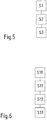
- FIG. 5 is a flowchart with the essential process steps for producing a contact tube 101 according to the invention shown schematically.
- a cylindrical tube made of, for example, aluminum or an aluminum alloy is provided in a first step S1.
- radial holes are drilled in the jacket 104 of the contact tube 101, which are equally spaced on a circular line on the circumference of the shell 104.
- the drilling of the holes is preferably carried out by a friction-flow-drilling process in which a rapidly rotating steel tool is pressed onto the jacket 104.
- the material of the shell goes into a flowable state, whereby on the one hand, a hole is formed and on the other hand, a bead 201 surrounding the hole is formed on the inside of the shell. Threads are cut in the holes thus formed to form threaded holes into which the contact screws 107A and 107B are screwed. If necessary, a flange 102 may be welded to the contact tube 101 before or after making the threaded holes 106A and 106B.
- the contact device produced thus far is used for producing a contact system.
- the method steps for producing the contact system are shown schematically in a flowchart in FIG FIG. 6 shown.
- a contact device 100 according to the invention is provided.
- the outer jacket 301 is removed from the cable 300 to expose the shield 302 formed as a corrugated pipe.
- the cable 300 is inserted with the end into the contact device 100, on which the corrugated tube 302 is exposed.
- the clamping screws 107A and 107B are screwed to contact the corrugated tube 302 in a substantially central position in the contact tube 101.
- another cable can be connected to the pin 111, which can be fastened with a screw.
Landscapes
- Cable Accessories (AREA)
Abstract
Description
- Die Erfindung betrifft eine Kontaktvorrichtung zum Kontaktieren eines koaxialen Kabels, dessen elektrischer Leiter von einem Schirm umgeben ist, der als Rohr, insbesondere als Wellrohr, ausgebildet ist. Weiterhin betrifft die Erfindung ein Kontaktsystem, das eine erfindungsgemäße Kontaktvorrichtung umfasst. Außerdem betrifft die Erfindung Verfahren zur Herstellung einer erfindungsgemäßen Kontaktvorrichtung und eines erfindungsgemäßen Kontaktsystems.
- Kontaktvorrichtungen und Kontaktsysteme der eingangs genannten Art werden beispielsweise bei Kabelgarnituren für ein koaxiales Kabel benötigt. Eine Kabelgarnitur ist ein Bauteil, das ein elektrisches Kabel abschließt oder mit einem weiteren Kabel verbindet.
- Eine Kabelgarnitur soll gute elektrische Kontakte zu dem Leiter und dem Schirm des Koaxialkabels herstellen und gleichzeitig verhindern, dass Feuchtigkeit oder Schmutz zwischen die Bestandteile des Kabels gelangt. Außerdem ist die elektrische Isolation zwischen dem elektrischen Leiter und dem Schirm des Koaxialkabels sicherzustellen. Als Schirm kommt bei dieser Art von Kabeln häufig ein Wellrohr zum Einsatz. Der Anschluss eines derartigen Hochspannungskabels zum Beispiel an dem Gehäuse einer elektrischen Garnitur oder an einem anderen Hochspannungskabel erfordert somit die Kontaktierung sowohl der Kabelader als auch des Schirms. Beim Übergang auf andere Bauteile soll der elektrische Leiter auch mechanisch stabil an das entsprechende Bauteil geführt werden.
- Eine gängige Methode zum stromtragfähigen Kontaktieren von Kabeln mit Metallwellmantel (Wellrohr) ist das Anschweißen oder Anlöten von Metallkontaktelementen. Diese Art der Kontaktierung ist anspruchsvoll und zeitintensiv. Darüber hinaus hängt die Qualität des Kontaktes stark von den Fertigkeiten des Montagepersonals ab, das den Kontakt herstellt. Eine gleichbleibend hohe Qualität der Kontakte ist mit den herkömmlichen Kontaktierungsmethoden daher nicht einfach zu erreichen.
- Hiervon ausgehend ist eine Aufgabe der vorliegenden Erfindung, eine Kontaktvorrichtung zu schaffen, die eines oder mehrere der eingangs genannten Probleme überwindet oder zumindest verbessert.
- Zur Lösung dieser Aufgabe schlägt die Erfindung nach einem ersten Aspekt eine Kontaktvorrichtung zum Kontaktieren eines Kabels mit einem isolierten elektrischen Leiter vor, der von einem Schirm umgeben ist, der als Rohr ausgebildet ist. Die Kontaktvorrichtung weist ein Kontaktrohr auf, welches das Kabel aufnimmt. Die Kontaktvorrichtung zeichnet sich dadurch aus, dass das Kontaktrohr wenigstens ein Gewindeloch mit einer darin aufgenommenen Klemmschraube aufweist, die den Schirm des Kabels kontaktiert.
- Ein Klemmkontakt zwischen dem Schirm des Kabels und dem Kontaktrohr hat den Vorteil, dass diese Art der Kontakte im Vergleich zu Schweißen oder Löten einfach herzustellen ist und auch in Bezug auf die Arbeitssicherheit Vorteile bietet. Gleichzeitig ist es möglich, mit Klemmkontakten eine gleichmäßigere Qualität der elektrischen Kontakte zu erreichen, die kaum von der Qualifikation und Fertigkeit des Montagepersonals abhängt. Ein weiterer Vorteil von Klemmkontakten ist, dass nahezu beliebige metallische Materialien miteinander kombiniert werden können, um einen elektrischen Kontakt herzustellen. Weiterhin sind für die Herstellung eines Klemmkontaktes nur einfache Werkzeuge notwendig.
- Bei einem vorteilhaften Ausführungsbeispiel sind bei der Kontaktvorrichtung mehrere Gewindelöcher mit jeweils einer Klemmschraube vorgesehen, die auf einer Kreislinie auf dem Umfang des Kontaktrohres gleichmäßig verteilt angeordnet sind.
- Diese Anordnung der Klemmschrauben ist vorteilhaft, weil ein Kabel in der Kontaktvorrichtung auf einfache Weise zentrisch angeordnet werden kann. Diese Anordnung hat im Falle eines Kurzschlusses zwischen dem Leiter des Kabels und dem Kontaktrohr den Vorteil, dass die dabei entstehenden elektrodynamischen Kräfte sich gegenseitig aufheben, wodurch die mechanische Belastung der Kontaktvorrichtung begrenzt wird.
- Bei einer vorteilhaften Weiterbildung der Kontaktvorrichtung sind die Gewindelöcher mit jeweils einer Klemmschraube auf mindestens zwei Kreislinien auf dem Umfang des Kontaktrohres auf jeder Kreislinie gleichmäßig verteilt angeordnet. Mit Vorteil sind in diesem Fall die Gewindelöcher auf benachbarten Kreislinien in Umfangsrichtung zueinander versetzt. Auf diese Weise wird erreicht, dass in dem Mantel des Kontaktrohres keine strukturellen Schwachstellen auftreten. Zudem wird auch der Anpressdruck der Klemmschrauben auf den Schirm des Kabels gleichmäßig verteilt.
- Zweckmäßigerweise kann das Kontaktrohr der Kontaktvorrichtung an einem Ende einen Befestigungsflansch aufweisen, um die Kontaktvorrichtung beispielsweise an einer elektrischen Anlage oder einer Kabelgarnitur zu befestigen.
- Bei einer Weiterbildung der Erfindung weist die Kontaktvorrichtung mindestens eine Kontaktstelle auf, die das Anschließen von Kabeln oder Litzen ermöglicht, z.B. zur Erdung der Kontaktvorrichtung. In diesem Fall kann die Kontaktstelle zweckmäßigerweise als Zapfen ausgebildet sein, der ein Innengewinde oder ein Außengewinde aufweist, um dort z.B. einen Kabelschuh oder ähnliches anzuschrauben. Denkbar ist auch, dass der Zapfen einen Gewindestift mit Außengewinde zur Befestigung von weiterführenden Kontaktelementen aufweist.
- Nach einem zweiten Aspekt schlägt die Erfindung ein Kontaktsystem vor, das eine erfindungsgemäße Kontaktvorrichtung sowie ein Kabel aufweist, das einen elektrischen Leiter aufweist, der von einem Schirm umgeben ist, der als Rohr ausgebildet ist.
- Das Kontaktsystem hat dieselben Vorteile, die bereits im Zusammenhang mit der Kontaktvorrichtung beschrieben wurden.
- Bei einem Ausführungsbeispiel ist der Schirm des Kabels von dem Kontaktsystem als ein Glattrohrmantel oder ein Wellrohrmantel ausgebildet. Welcher Manteltyp gewählt wird hängt von den Anwendungsfällen ab. Grundsätzlich weist ein Wellrohrmantel eine höhere Biegsamkeit als ein Glattrohrmantel auf.
Nach einem dritten Aspekt schlägt die Erfindung ein Verfahren zur Herstellung einer erfindungsgemäßen Kontaktvorrichtung vor. Das Verfahren umfasst: - Bereitstellen eines Kontaktrohres;
- Herstellen von gleichmäßig beanstandeten radialen Löchern auf einer Kreislinie in einem Mantel des Kontaktrohres und
- Schneiden von Gewinde in die zuvor gebohrten Löcher.
- Gemäß einer Weiterbildung des Herstellungsverfahrens für die Kontaktvorrichtung erfolgt das Herstellen der radialen Löcher durch einen Reib-Fließ-Bohr-Prozess, durch Tiefziehen oder durch Anbringen einer Nietmutter.
- Dier genannten Verfahren zur Herstellung der radialen Löcher haben den Vorteil, dass eine größere Materialstärke im Vergleich zu der Wandstärke des Kontaktrohres für das Gewinde zur Verfügung steht und somit die Länge des Gewindeloches größer wird und ein besserer Halt der Klemmschraube in dem Kontaktrohr erreicht wird. Dadurch ist es beispielsweise möglich, größere Klemmkräfte mit den Klemmschrauben zu übertragen.
- Schließlich schlägt die Erfindung nach einem vierten Aspekt ein Verfahren zur Herstellung eines Kontaktsystems vor. Das Verfahren umfasst:
- Bereitstellen einer Kontaktvorrichtung nach einem der vorstehenden Ansprüche;
- Entfernen eines äußeren Mantels von einem Kabel mit einem als Rohr ausgebildeten Schirm, um den Schirm freizulegen;
- Einführen des Kabels in die Kontaktvorrichtung; und
- Eindrehen der Klemmschrauben, um den Schirm zu kontaktieren.
- Nachfolgend wird die Erfindung anhand einer Ausführungsform unter Bezugnahme auf die begleitenden Figuren exemplarisch näher erläutert. Alle Figuren sind rein schematisch und nicht maßstäblich. Es zeigen:
- Fig. 1
- eine perspektivische Ansicht einer erfindungsgemäßen Kontaktvorrichtung;
- Fig. 2A
- einen Querschnitt der Kontaktvorrichtung aus Figur;
- Fig. 2B
- ein vergrößerter Ausschnitt aus
Figur 2A ; - Fig. 3
- den Aufbau eines Kabels, das mit der Kontaktvorrichtung kontaktiert wird;
- Fig. 4
- die Kontaktvorrichtung aus
Figur 1 in einer Draufsicht mit einem montierten Kabel; - Fig. 5
- ein Flussdiagramm mit den Verfahrensschritten zur Herstellung einer erfindungsgemäßen Kontaktvorrichtung; und
- Fig. 6
- ein Flussdiagramm mit den Verfahrensschritten zur Herstellung eines erfindungsgemäßen Kontaktsystems.
- Gleiche oder ähnliche Elemente sind in den Figuren mit gleichen oder ähnlichen Bezugszeichen versehen.
-
Figur 1 zeigt eine perspektivische Ansicht auf eine Kontaktvorrichtung 100, die ein Kontaktrohr 101 aufweist. Das Kontaktrohr 101 hat in unterschiedlichen Ausführungsbeispielen einen Durchmesser von 10 - 20 cm und eine Höhe von 10-30 cm. Falls erforderlich, können diese Abmessungen auch anders gewählt sein, um das Kontaktrohr 101 an bestimmte Anwendungsfälle anzupassen. An dem inFigur 1 untenliegenden Ende des Kontaktrohres 101 ist an das Kontaktrohr ein Flansch 102 angeschweißt. Der Flansch 102 ist entlang seines Umfangs mit Befestigungslöchern 103 zur Aufnahme von Befestigungsschrauben (nicht dargestellt) versehen, um die Kontaktvorrichtung an einer elektrischen Einrichtung zu befestigen, wie zum Beispiel einem Transformator oder einer Kabelgarnitur (inFigur 1 nicht dargestellt). Das Kontaktrohr 101 und der Flansch 102 sind aus Aluminium oder einer Aluminiumlegierung hergestellt. Grundsätzlich kommen auch andere Metalle hierfür infrage, beispielsweise Kupfer oder andere gut leitende Metalle. - In dem Mantel 104 des Kontaktrohres 101 sind Gewindelöcher 106A und 106B vorgesehen, die jeweils eine Klemmschraube 107A bzw. 107B aufnehmen. Die Gewindelöcher 106A sind entlang einer Kreislinie 108A und die Gewindelöcher 106B sind entlang einer Kreislinie 108B in Umfangsrichtung in gleichmäßigem Abstand verteilt. Obwohl in
Figur 1 zwei Kreislinien 108A und 108B dargestellt sind, können in anderen Ausführungsbeispielen die Gewindelöcher auch auf nur einer einzigen Kreislinie oder auf mehr als zwei Kreislinien angeordnet sein. Die diesbezügliche Ausgestaltung der erfindungsgemäßen Kontaktvorrichtung 100 hängt von dem jeweiligen Anwendungsfall ab, insbesondere davon, wie viele Klemmschrauben benötigt werden. - In jedem Fall sind die Gewindelöcher auf unterschiedlichen Kreislinien bevorzugt versetzt zueinander angeordnet. Bei dem in
Figur 1 gezeigten Ausführungsbeispiel liegt jeweils ein Gewindeloch 106B auf der Kreislinie 108B in Umfangsrichtung genau zwischen zwei Gewindelöchern 106A, die sich auf der Kreislinie 108A befinden. Dadurch wird vermieden, dass entlang axialer Richtungen der Mantel 104 des Kontaktrohres 101 durch hintereinander angeordnete Bohrungen strukturell geschwächt wird. - Die Kontaktvorrichtung 100 weist darüber hinaus noch einen in radialer Richtung abstehenden Zapfen 111 auf, der an dem Mantel 104 des Kontaktrohres in einem bestimmten Abstand zwischen dem Flansch 102 und der Kreislinie 108B angeschweißt ist und eine Kontaktstelle zum Anschluss eines weiteren Kabels bildet. Zu diesem Zweck weist der Zapfen 111 ein zentrales Gewindeloch 112 auf, um zum Beispiel einen Kabelschuh des weiteren Kabels festzuschrauben.
- Die in
Figur 1 dargestellten Schrauben 107A, 107B sind mit einem Innensechskant versehen. Grundsätzlich können für die vorliegende Erfindung auch andere Arten von Schrauben verwendet werden, insbesondere auch Schrauben mit einem Abreisskopf. -
Figur 2A zeigt einen Querschnitt durch das Kontaktrohr 101 auf der Ebene der Kreislinie 108B. In dieser Ansicht ist deutlich zu erkennen, dass die Gewindelöcher 106B in gleichmäßigem Abstand auf einer Umfangslinie des Mantels 104 des Kontaktrohres 101 verteilt sind. -
Figur 2B zeigt einen vergrößerten Ausschnitt ausFigur 2A und illustriert eine herstellungsbedingte Besonderheit des Kontaktrohres 101. Die Bohrungen für die Gewindelöcher werden durch einen Reib-Fließ-Bohr-Prozess hergestellt. Dabei wird ein schnell rotierendes Stahlwerkzeug in radialer Richtung auf den Mantel 104 des Kontaktrohres 101 gepresst. Durch die Reibungswärme wird das Metall in einen fließförmigen Zustand versetzt, wodurch das Material unter dem rotierenden Werkzeug verdrängt wird. Dabei bilden sich rund um die Bohrungen in dem Kontaktrohr 101 Wülste 201 um das jeweilige Bohrloch herum, die in radialer Richtung in dem Kontaktrohr 101 nach innen gerichtet sind. Dabei entsteht ein Bohrloch, dessen Länge I größer ist als die Dicke d des Mantels 104 des Kontaktrohres 101. In das Bohrloch wird ein Gewinde geschnitten, um ein Gewindeloch herzustellen, zum Beispiel ein Gewindeloch 106A oder 106B. Die Länge des Gewindeloches entspricht dabei der Länge I des Bohrloches. Im Gegensatz dazu würde die Länge eines herkömmlich mit einem Spiralbohrer hergestellten Gewindeloches der Länge der Manteldicke d des Kontaktrohres 101 entsprechen. Im Vergleich dazu ist das Gewindeloch bei dem erfindungsgemäßen Kontaktrohr wegen seiner größeren Länge mechanisch stabiler, sodass es möglich ist, vergleichsweise größere Klemmkräfte mit den Klemmschrauben 107A und 107B auszuüben. -
Figur 3 zeigt schematisch den Aufbau eines Hochspannungskabels 300, das einen äußeren Mantel 301 aufweist. Ein Schirm 302 umgibt einen mehradrigen Leiter 303, der aus Einzeladern 304 gebildet ist. Die Einzeladern 304 sind von einer Hülle 306 umgeben, welche die Einzeladern 304 zu dem Leiter 303 bündelt. Der Schirm 302 ist als Wellrohr ausgebildet. Der elektrische Leiter 303 ist von einem Dielektrikum 307 umgeben, an das sich eine Isolationsschicht 308 anschließt, die zwischen dem Dielektrikum 307 und dem Schirm 302 liegt. In anderen Ausführungsbeispielen ist der Leiter 303 als massiver Einzelleiter ausgebildet. -
Figur 4 zeigt eine Querschnittsansicht durch die Kontaktvorrichtung 100 mit einem montierten HV Koaxialkabel 301, wobei die Schnittfläche entlang der Linie 4-4 inFigur 1 verläuft. Hierbei ist zu beachten, dass inFigur 4 im Unterschied zuFigur 1 die Schrauben 107A und 107B in die Gewindelöcher 106A bzw. 106B des Kontaktrohres 101 eingedreht sind. Von dem Kabel 300 ist der äußere Mantel 301 auf einer Länge entfernt, die ungefähr der Länge des Kontaktrohres 101 zuzüglich der Länge entspricht, die benötigt wird, um das Kabel 301 im Inneren einer elektrischen Einrichtung mit einem dafür vorgesehenen Anschluss zu verbinden. Im Inneren der Kontaktvorrichtung 100 liegt das Wellrohr 302 frei. Die Schrauben 107A und 107B sind eingedreht, klemmen das Wellrohr 302 im Wesentlichen in der Mitte des Kontaktrohres 101 fest und stellen einen elektrisch leitenden Kontakt zwischen dem Kontaktrohr 101 und dem Wellrohr 302 her. Diese Anordnung hat auch den Vorteil, dass bei einem Kurzschluss und hohen Stromflüssen durch den Leiter 303 und das Kontaktrohr 101 sich die dabei entstehenden elektrodynamischen Kräfte gegenseitig aufheben. Insbesondere hat die Anordnung aber den Vorteil, dass auf eine einfache Weise reproduzierbare elektrische Kontakte zwischen dem Wellrohr 302 und dem Kontaktrohr 101 herstellbar sind. - Die auf jeweils einer Kreislinie 108A bzw. 108B gleichmäßig beabstandete Anordnung der Klemmschrauben 107A und 107B, die auf unterschiedlichen Kreislinien zueinander versetzt sind, führt unter anderem auch dazu, dass die Klemmkräfte auf den Schirm 302 vergleichsweise gleichmäßig verteilt sind, was sich günstig auf die Formstabilität des Schirmes 302 auswirkt.
- In
Figur 5 ist ein Flussdiagramm mit den wesentlichen Verfahrensschritten zur Herstellung eines erfindungsgemäßen Kontaktrohres 101 schematisch dargestellt. In einem ersten Schritt S1 wird ein zylindrisches Rohr aus beispielsweise Aluminium oder einer Aluminiumlegierung bereitgestellt. In einem nächsten Schritt S2 werden in den Mantel 104 des Kontaktrohres 101 radiale Löcher gebohrt, die auf einer Kreislinie auf dem Umfang des Mantels 104 gleichmäßig beabstandet sind. Das Bohren der Löcher erfolgt vorzugsweise mit einem Reib-Fließ-Bohr-Prozess bei dem ein schnell rotierendes Stahlwerkzeug auf den Mantel 104 gedrückt wird. Dadurch geht das Material des Mantels in einen fließfähigen Zustand über, wodurch zum einen ein Loch entsteht und zum anderen ein das Loch umgebender Wulst 201 auf der Innenseite des Mantels entsteht. In die so gebildeten Löcher werden Gewinde geschnitten, sodass Gewindelöcher entstehen, in welche die Kontaktschrauben 107A bzw. 107B eingedreht werden. Im Bedarfsfall kann an das Kontaktrohr 101 vor oder nach dem Herstellen der Gewindelöcher 106A und 106B ein Flansch 102 angeschweißt werden. - Die insoweit hergestellte Kontaktvorrichtung wird zum Herstellen eines Kontaktsystems verwendet. Die Verfahrensschritte zur Herstellung des Kontaktsystems sind schematisch in einem Flussdiagramm in
Figur 6 gezeigt. In einem ersten Schritt S10 wird eine erfindungsgemäße Kontaktvorrichtung 100 bereitgestellt. Dann wird in einem Schritt S11 der äußere Mantel 301 von dem Kabel 300 entfernt, um den als Wellrohr ausgebildeten Schirm 302 freizulegen. In einem Schritt S12 wird das Kabel 300 mit dem Ende in die Kontaktvorrichtung 100 eingeführt, an dem das Wellrohr 302 freigelegt ist. Schließlich werden in Schritt S13 die Klemmschrauben 107A und 107B eingedreht, um das Wellrohr 302 in einer im Wesentlichen zentralen Position in dem Kontaktrohr 101 zu kontaktieren. - Zum Abschluss der Kontaktierung kann ein weiteres Kabel an den Zapfen 111 angeschlossen werden, welches mit einer Schraube befestigbar ist.
-
- 100
- Kontaktvorrichtung
- 101
- Kontaktrohr
- 102
- Befestigungsflansch
- 103
- Befestigungslöcher
- 106A, 106B
- Gewindelöcher
- 107A, 107B
- Klemmschraube
- 108A, 108B
- Kreislinie
- 111
- Zapfen
- 112
- Gewindeloch
- 113
- Außengewinde
- 201
- Wülste
- 300
- Kabel
- 301
- äußerer Isolationsmantel
- 302
- Schirm
- 303
- mehradriger Leiter
- 304
- Einzeladern
- 306
- Hülle
- 307
- Dielektrikum
- 308
- Pufferschicht
Claims (11)
- Kontaktvorrichtung (100) zum Kontaktieren eines Kabels (300) mit einem isolierten elektrischen Leiter (303), der von einem Schirm (302) umgeben ist, der als Rohr ausgebildet ist, wobei die Kontaktvorrichtung ein Kontaktrohr (101) aufweist, welches das Kabel (300) aufnimmt,
dadurch gekennzeichnet, dass
das Kontaktrohr (101) wenigstens ein Gewindeloch (106A, 106B) mit einer darin aufgenommenen Klemmschraube (107A; 107B) aufweist, die den Schirm (302) des Kabels (300) kontaktiert. - Kontaktvorrichtung nach Anspruch 1, dadurch gekennzeichnet, dass mehrere Gewindelöcher (106A, 106B) mit jeweils einer Klemmschraube (107A, 107B) vorgesehen sind, die auf einer Kreislinie (108A, 108B) auf dem Umfang des Kontaktrohres (101) gleichmäßig verteilt angeordnet sind.
- Kontaktvorrichtung nach Anspruch 2, dadurch gekennzeichnet, dass die Gewindelöcher (106A, 106B) mit jeweils einer Klemmschraube (107A, 107B) auf mindestens zwei Kreislinien (108A, 108B) auf dem Umfang des Kontaktrohres (101) auf jeder Kreislinie (108A, 108B) gleichmäßig verteilt angeordnet sind.
- Kontaktvorrichtung nach Anspruch 3, dadurch gekennzeichnet, dass die Gewindelöcher (106A, 106B) auf benachbarten Kreislinien in Umfangsrichtung zueinander versetzt sind.
- Kontaktvorrichtung nach einem der vorstehenden Ansprüche, dadurch gekennzeichnet, dass die Kontaktvorrichtung mindestens eine Kontaktstelle aufweist, die das Anschließen von Kabeln oder Litzen ermöglicht.
- Kontaktvorrichtung nach Anspruch 5, dadurch gekennzeichnet, dass die Kontaktstelle als Zapfen (111) ausgebildet ist, der ein Innengewinde oder ein Außengewinde aufweist.
- Kontaktsystem, das eine Kontaktvorrichtung (100) nach einem der vorstehenden Ansprüche sowie ein Kabel (300) aufweist, das einen elektrischen Leiter (303) aufweist, der von einem Schirm (302) umgeben ist, der als Rohr ausgebildet ist.
- Kontaktsystem nach Anspruch 7, dadurch gekennzeichnet, dass der Schirm (302) ein Glattrohrmantel oder ein Wellrohrmantel ist.
- Verfahren zur Herstellung einer Kontaktvorrichtung nach einem der vorstehenden Ansprüche, wobei das Verfahren umfasst:- Bereitstellen eines Kontaktrohres (101);- Herstellen von gleichmäßig beanstandeten radialen Löchern auf einer Kreislinie (108A, 108B) in einem Mantel (104) des Kontaktrohres (101) und- Schneiden von Gewinde in die zuvor gebohrten Löcher.
- Verfahren nach Anspruch 9, dadurch gekennzeichnet, dass das Herstellen der radialen Löcher durch einen Reib-Fließ-Bohr-Prozess, durch Tiefziehen oder durch Anbringen einer Nietmutter erfolgt.
- Verfahren zur Herstellung eines Kontaktsystems, wobei das Verfahren umfasst:- Bereitstellen einer Kontaktvorrichtung (100) nach einem der vorstehenden Ansprüche;- Entfernen eines äußeren Mantels (301) von einem Kabel mit einem als Rohr ausgebildeten Schirm (302), um den Schirm freizulegen;- Einführen des Kabels (300) in die Kontaktvorrichtung (100); und- Eindrehen von Klemmschrauben (106A, 106B), um den Schirm (302) zu kontaktieren.
Priority Applications (2)
| Application Number | Priority Date | Filing Date | Title |
|---|---|---|---|
| DK17306725.7T DK3496208T3 (da) | 2017-12-08 | 2017-12-08 | Kontaktanordning og kontaktsystem til koaksiale højspændingskabler |
| EP17306725.7A EP3496208B1 (de) | 2017-12-08 | 2017-12-08 | Kontaktvorrichtung und kontaktsystem für koaxiale hochspannungskabel |
Applications Claiming Priority (1)
| Application Number | Priority Date | Filing Date | Title |
|---|---|---|---|
| EP17306725.7A EP3496208B1 (de) | 2017-12-08 | 2017-12-08 | Kontaktvorrichtung und kontaktsystem für koaxiale hochspannungskabel |
Publications (2)
| Publication Number | Publication Date |
|---|---|
| EP3496208A1 true EP3496208A1 (de) | 2019-06-12 |
| EP3496208B1 EP3496208B1 (de) | 2024-04-10 |
Family
ID=60673875
Family Applications (1)
| Application Number | Title | Priority Date | Filing Date |
|---|---|---|---|
| EP17306725.7A Active EP3496208B1 (de) | 2017-12-08 | 2017-12-08 | Kontaktvorrichtung und kontaktsystem für koaxiale hochspannungskabel |
Country Status (2)
| Country | Link |
|---|---|
| EP (1) | EP3496208B1 (de) |
| DK (1) | DK3496208T3 (de) |
Citations (4)
| Publication number | Priority date | Publication date | Assignee | Title |
|---|---|---|---|---|
| US20060054341A1 (en) * | 2004-09-13 | 2006-03-16 | Delbert Auray | Snap fit electrical connector assembly with conical outer snap fit retainer and one or more internal snap fit wire retainers |
| US20080261447A1 (en) * | 2007-04-23 | 2008-10-23 | D Addario James | Plug connector |
| CN103531986B (zh) * | 2013-10-16 | 2016-05-25 | 广东吉熙安电缆附件有限公司 | 一种电缆铠装的接地方法 |
| WO2017030271A1 (ko) * | 2015-08-14 | 2017-02-23 | 엘에스전선 주식회사 | 케이블의 접속구조, 케이블의 접속방법 및 이에 이용되는 케이블 커넥터용 도체 슬리브 |
Family Cites Families (7)
| Publication number | Priority date | Publication date | Assignee | Title |
|---|---|---|---|---|
| US2947800A (en) * | 1955-10-10 | 1960-08-02 | Thomas & Betts Corp | Insulated electrical raceway fitting |
| DE202006018023U1 (de) * | 2006-11-24 | 2007-02-01 | Phoenix Contact Gmbh & Co. Kg | Klemmhülse für elektrische Leiter |
| DE102008025428B4 (de) * | 2008-05-27 | 2022-11-10 | Phoenix Contact Gmbh & Co. Kg | Verfahren zur Herstellung einer elektrische Anschlusseinrichtung |
| JP5009944B2 (ja) * | 2009-02-05 | 2012-08-29 | 博保 皆吉 | 連結具を用いた連結方法 |
| DE102010033808B4 (de) * | 2010-08-09 | 2016-12-22 | Phoenix Contact Gmbh & Co. Kg | Reihenklemme |
| US9816544B2 (en) * | 2014-06-25 | 2017-11-14 | Ford Global Technologies, Llc | Method of forming a grounding point on an aluminum member |
| CN104967087A (zh) * | 2015-04-30 | 2015-10-07 | 科耐特电缆附件股份有限公司 | 高压电缆橡胶件接头试验用连管 |
-
2017
- 2017-12-08 EP EP17306725.7A patent/EP3496208B1/de active Active
- 2017-12-08 DK DK17306725.7T patent/DK3496208T3/da active
Patent Citations (4)
| Publication number | Priority date | Publication date | Assignee | Title |
|---|---|---|---|---|
| US20060054341A1 (en) * | 2004-09-13 | 2006-03-16 | Delbert Auray | Snap fit electrical connector assembly with conical outer snap fit retainer and one or more internal snap fit wire retainers |
| US20080261447A1 (en) * | 2007-04-23 | 2008-10-23 | D Addario James | Plug connector |
| CN103531986B (zh) * | 2013-10-16 | 2016-05-25 | 广东吉熙安电缆附件有限公司 | 一种电缆铠装的接地方法 |
| WO2017030271A1 (ko) * | 2015-08-14 | 2017-02-23 | 엘에스전선 주식회사 | 케이블의 접속구조, 케이블의 접속방법 및 이에 이용되는 케이블 커넥터용 도체 슬리브 |
Also Published As
| Publication number | Publication date |
|---|---|
| EP3496208B1 (de) | 2024-04-10 |
| DK3496208T3 (da) | 2024-07-08 |
Similar Documents
| Publication | Publication Date | Title |
|---|---|---|
| EP2683034B1 (de) | Verfahren zum elektrisch leitenden Verbinden der elektrischen Leiter von zwei Hochspannungskabeln | |
| DE19533721C2 (de) | Verbindungseinrichtung zum Anschluß eines Koaxialsteckers an ein Wellrohrkoaxialkabel | |
| EP2850696B1 (de) | Verfahren und vorrichtung zum erzeugen einer wirkverbindung zwischen einem verbinder und einem kabel | |
| EP3417514A1 (de) | Kontaktsystem zur kontaktierung eines schirmgeflechts und eines kontaktelements | |
| EP2360804A1 (de) | Anordnung zum Verbinden von zwei Energiekabeln | |
| EP3021420A1 (de) | Mehradriges geschirmtes Kabel und Verfahren zur Herstellung eines derartigen Kabels | |
| DE102017215970B3 (de) | Verfahren zum Verbinden einer elektrischen Aluminiumleitung mit einem Aluminiumrohr | |
| EP0793295A2 (de) | Einrichtung zur Verbindung eines Koaxialsteckers mit einem Koaxialkabel | |
| EP2719019B1 (de) | System aus einem koaxialsteckverbinder und einem koaxialkabel | |
| DE102011108123A1 (de) | Kabelanschlussbauteil sowie Kabelanschlusseinrichtung und Kabelverbindungseinrichtung mit einem Kabelanschlussbauteil | |
| DE102014105817A1 (de) | Kabelendgarnitur | |
| EP2565898B1 (de) | Elektrische Schaltanlage | |
| DE202019100073U1 (de) | Schirmbuchse für einen Schirm einer Hochvoltleitung und Setzwerkzeug | |
| DE102018130746A1 (de) | Stromleiterbrücke und Verfahren zum Ausbilden einer Stromleiterbrücke | |
| EP2874236B1 (de) | Kontaktiervorrichtung zum Kontaktieren eines Kabelschirms | |
| EP3496208B1 (de) | Kontaktvorrichtung und kontaktsystem für koaxiale hochspannungskabel | |
| EP3490074B1 (de) | Anordnung zum kontaktieren eines schirms eines kabels | |
| DE202009005412U1 (de) | Einrichtung zur Verbindung zweier ein- oder mehrpoliger elektrischer Kabel miteinander | |
| EP2765686B1 (de) | Abgewinkelte Verbindungshülse und elektrische Maschine mit derartiger Verbindungshülse | |
| DE102015005993B3 (de) | Verfahren zum Verbinden von Hochspannungskabeln mit mehrdrähtigen Leitern | |
| EP2104959B1 (de) | Kabeleinführung | |
| EP0069803A2 (de) | Batterieklemme | |
| EP4070417B1 (de) | Elektrische koppelvorrichtung, elektrisches system und verfahren zum elektrischen sowie mechanischen koppeln | |
| BE1025978B1 (de) | Verfahren zur Herstellung einer Gewindebohrung in einem Stromschienenstück einer Anschlussklemme | |
| EP2571102B1 (de) | Vorrichtung zum Ankontaktieren des Leitungsschirms eines Koaxialkabels |
Legal Events
| Date | Code | Title | Description |
|---|---|---|---|
| PUAI | Public reference made under article 153(3) epc to a published international application that has entered the european phase |
Free format text: ORIGINAL CODE: 0009012 |
|
| STAA | Information on the status of an ep patent application or granted ep patent |
Free format text: STATUS: REQUEST FOR EXAMINATION WAS MADE |
|
| STAA | Information on the status of an ep patent application or granted ep patent |
Free format text: STATUS: EXAMINATION IS IN PROGRESS |
|
| 17P | Request for examination filed |
Effective date: 20180529 |
|
| AK | Designated contracting states |
Kind code of ref document: A1 Designated state(s): AL AT BE BG CH CY CZ DE DK EE ES FI FR GB GR HR HU IE IS IT LI LT LU LV MC MK MT NL NO PL PT RO RS SE SI SK SM TR |
|
| AX | Request for extension of the european patent |
Extension state: BA ME |
|
| 17Q | First examination report despatched |
Effective date: 20190611 |
|
| REG | Reference to a national code |
Ref country code: DE Ref legal event code: R079 Ipc: H01R0013659100 Ref country code: DE Ref legal event code: R079 Ref document number: 502017016015 Country of ref document: DE Free format text: PREVIOUS MAIN CLASS: H01R0004360000 Ipc: H01R0013659100 |
|
| GRAP | Despatch of communication of intention to grant a patent |
Free format text: ORIGINAL CODE: EPIDOSNIGR1 |
|
| STAA | Information on the status of an ep patent application or granted ep patent |
Free format text: STATUS: GRANT OF PATENT IS INTENDED |
|
| RIC1 | Information provided on ipc code assigned before grant |
Ipc: H01R 13/74 20060101ALI20231010BHEP Ipc: H01R 4/64 20060101ALI20231010BHEP Ipc: H01R 4/36 20060101ALI20231010BHEP Ipc: H01R 13/6591 20110101AFI20231010BHEP |
|
| INTG | Intention to grant announced |
Effective date: 20231106 |
|
| GRAS | Grant fee paid |
Free format text: ORIGINAL CODE: EPIDOSNIGR3 |
|
| GRAA | (expected) grant |
Free format text: ORIGINAL CODE: 0009210 |
|
| STAA | Information on the status of an ep patent application or granted ep patent |
Free format text: STATUS: THE PATENT HAS BEEN GRANTED |
|
| AK | Designated contracting states |
Kind code of ref document: B1 Designated state(s): AL AT BE BG CH CY CZ DE DK EE ES FI FR GB GR HR HU IE IS IT LI LT LU LV MC MK MT NL NO PL PT RO RS SE SI SK SM TR |
|
| REG | Reference to a national code |
Ref country code: GB Ref legal event code: FG4D Free format text: NOT ENGLISH |
|
| REG | Reference to a national code |
Ref country code: CH Ref legal event code: EP |
|
| REG | Reference to a national code |
Ref country code: DE Ref legal event code: R096 Ref document number: 502017016015 Country of ref document: DE |
|
| REG | Reference to a national code |
Ref country code: IE Ref legal event code: FG4D Free format text: LANGUAGE OF EP DOCUMENT: GERMAN |
|
| REG | Reference to a national code |
Ref country code: DK Ref legal event code: T3 Effective date: 20240704 |
|
| REG | Reference to a national code |
Ref country code: SE Ref legal event code: TRGR |
|
| REG | Reference to a national code |
Ref country code: LT Ref legal event code: MG9D |
|
| REG | Reference to a national code |
Ref country code: NL Ref legal event code: MP Effective date: 20240410 |
|
| PG25 | Lapsed in a contracting state [announced via postgrant information from national office to epo] |
Ref country code: NL Free format text: LAPSE BECAUSE OF FAILURE TO SUBMIT A TRANSLATION OF THE DESCRIPTION OR TO PAY THE FEE WITHIN THE PRESCRIBED TIME-LIMIT Effective date: 20240410 |
|
| PG25 | Lapsed in a contracting state [announced via postgrant information from national office to epo] |
Ref country code: NL Free format text: LAPSE BECAUSE OF FAILURE TO SUBMIT A TRANSLATION OF THE DESCRIPTION OR TO PAY THE FEE WITHIN THE PRESCRIBED TIME-LIMIT Effective date: 20240410 |
|
| PG25 | Lapsed in a contracting state [announced via postgrant information from national office to epo] |
Ref country code: IS Free format text: LAPSE BECAUSE OF FAILURE TO SUBMIT A TRANSLATION OF THE DESCRIPTION OR TO PAY THE FEE WITHIN THE PRESCRIBED TIME-LIMIT Effective date: 20240810 |
|
| PG25 | Lapsed in a contracting state [announced via postgrant information from national office to epo] |
Ref country code: BG Free format text: LAPSE BECAUSE OF FAILURE TO SUBMIT A TRANSLATION OF THE DESCRIPTION OR TO PAY THE FEE WITHIN THE PRESCRIBED TIME-LIMIT Effective date: 20240410 |
|
| PG25 | Lapsed in a contracting state [announced via postgrant information from national office to epo] |
Ref country code: FI Free format text: LAPSE BECAUSE OF FAILURE TO SUBMIT A TRANSLATION OF THE DESCRIPTION OR TO PAY THE FEE WITHIN THE PRESCRIBED TIME-LIMIT Effective date: 20240410 Ref country code: HR Free format text: LAPSE BECAUSE OF FAILURE TO SUBMIT A TRANSLATION OF THE DESCRIPTION OR TO PAY THE FEE WITHIN THE PRESCRIBED TIME-LIMIT Effective date: 20240410 |
|
| PG25 | Lapsed in a contracting state [announced via postgrant information from national office to epo] |
Ref country code: GR Free format text: LAPSE BECAUSE OF FAILURE TO SUBMIT A TRANSLATION OF THE DESCRIPTION OR TO PAY THE FEE WITHIN THE PRESCRIBED TIME-LIMIT Effective date: 20240711 |
|
| PG25 | Lapsed in a contracting state [announced via postgrant information from national office to epo] |
Ref country code: PT Free format text: LAPSE BECAUSE OF FAILURE TO SUBMIT A TRANSLATION OF THE DESCRIPTION OR TO PAY THE FEE WITHIN THE PRESCRIBED TIME-LIMIT Effective date: 20240812 |
|
| PG25 | Lapsed in a contracting state [announced via postgrant information from national office to epo] |
Ref country code: ES Free format text: LAPSE BECAUSE OF FAILURE TO SUBMIT A TRANSLATION OF THE DESCRIPTION OR TO PAY THE FEE WITHIN THE PRESCRIBED TIME-LIMIT Effective date: 20240410 |
|
| PG25 | Lapsed in a contracting state [announced via postgrant information from national office to epo] |
Ref country code: PL Free format text: LAPSE BECAUSE OF FAILURE TO SUBMIT A TRANSLATION OF THE DESCRIPTION OR TO PAY THE FEE WITHIN THE PRESCRIBED TIME-LIMIT Effective date: 20240410 |
|
| PG25 | Lapsed in a contracting state [announced via postgrant information from national office to epo] |
Ref country code: LV Free format text: LAPSE BECAUSE OF FAILURE TO SUBMIT A TRANSLATION OF THE DESCRIPTION OR TO PAY THE FEE WITHIN THE PRESCRIBED TIME-LIMIT Effective date: 20240410 |
|
| PG25 | Lapsed in a contracting state [announced via postgrant information from national office to epo] |
Ref country code: PT Free format text: LAPSE BECAUSE OF FAILURE TO SUBMIT A TRANSLATION OF THE DESCRIPTION OR TO PAY THE FEE WITHIN THE PRESCRIBED TIME-LIMIT Effective date: 20240812 Ref country code: PL Free format text: LAPSE BECAUSE OF FAILURE TO SUBMIT A TRANSLATION OF THE DESCRIPTION OR TO PAY THE FEE WITHIN THE PRESCRIBED TIME-LIMIT Effective date: 20240410 Ref country code: NO Free format text: LAPSE BECAUSE OF FAILURE TO SUBMIT A TRANSLATION OF THE DESCRIPTION OR TO PAY THE FEE WITHIN THE PRESCRIBED TIME-LIMIT Effective date: 20240710 Ref country code: LV Free format text: LAPSE BECAUSE OF FAILURE TO SUBMIT A TRANSLATION OF THE DESCRIPTION OR TO PAY THE FEE WITHIN THE PRESCRIBED TIME-LIMIT Effective date: 20240410 Ref country code: IS Free format text: LAPSE BECAUSE OF FAILURE TO SUBMIT A TRANSLATION OF THE DESCRIPTION OR TO PAY THE FEE WITHIN THE PRESCRIBED TIME-LIMIT Effective date: 20240810 Ref country code: HR Free format text: LAPSE BECAUSE OF FAILURE TO SUBMIT A TRANSLATION OF THE DESCRIPTION OR TO PAY THE FEE WITHIN THE PRESCRIBED TIME-LIMIT Effective date: 20240410 Ref country code: GR Free format text: LAPSE BECAUSE OF FAILURE TO SUBMIT A TRANSLATION OF THE DESCRIPTION OR TO PAY THE FEE WITHIN THE PRESCRIBED TIME-LIMIT Effective date: 20240711 Ref country code: FI Free format text: LAPSE BECAUSE OF FAILURE TO SUBMIT A TRANSLATION OF THE DESCRIPTION OR TO PAY THE FEE WITHIN THE PRESCRIBED TIME-LIMIT Effective date: 20240410 Ref country code: ES Free format text: LAPSE BECAUSE OF FAILURE TO SUBMIT A TRANSLATION OF THE DESCRIPTION OR TO PAY THE FEE WITHIN THE PRESCRIBED TIME-LIMIT Effective date: 20240410 Ref country code: BG Free format text: LAPSE BECAUSE OF FAILURE TO SUBMIT A TRANSLATION OF THE DESCRIPTION OR TO PAY THE FEE WITHIN THE PRESCRIBED TIME-LIMIT Effective date: 20240410 Ref country code: RS Free format text: LAPSE BECAUSE OF FAILURE TO SUBMIT A TRANSLATION OF THE DESCRIPTION OR TO PAY THE FEE WITHIN THE PRESCRIBED TIME-LIMIT Effective date: 20240710 |
|
| REG | Reference to a national code |
Ref country code: DE Ref legal event code: R097 Ref document number: 502017016015 Country of ref document: DE |
|
| PG25 | Lapsed in a contracting state [announced via postgrant information from national office to epo] |
Ref country code: EE Free format text: LAPSE BECAUSE OF FAILURE TO SUBMIT A TRANSLATION OF THE DESCRIPTION OR TO PAY THE FEE WITHIN THE PRESCRIBED TIME-LIMIT Effective date: 20240410 |
|
| PG25 | Lapsed in a contracting state [announced via postgrant information from national office to epo] |
Ref country code: CZ Free format text: LAPSE BECAUSE OF FAILURE TO SUBMIT A TRANSLATION OF THE DESCRIPTION OR TO PAY THE FEE WITHIN THE PRESCRIBED TIME-LIMIT Effective date: 20240410 |
|
| PG25 | Lapsed in a contracting state [announced via postgrant information from national office to epo] |
Ref country code: SK Free format text: LAPSE BECAUSE OF FAILURE TO SUBMIT A TRANSLATION OF THE DESCRIPTION OR TO PAY THE FEE WITHIN THE PRESCRIBED TIME-LIMIT Effective date: 20240410 Ref country code: RO Free format text: LAPSE BECAUSE OF FAILURE TO SUBMIT A TRANSLATION OF THE DESCRIPTION OR TO PAY THE FEE WITHIN THE PRESCRIBED TIME-LIMIT Effective date: 20240410 |
|
| PG25 | Lapsed in a contracting state [announced via postgrant information from national office to epo] |
Ref country code: SM Free format text: LAPSE BECAUSE OF FAILURE TO SUBMIT A TRANSLATION OF THE DESCRIPTION OR TO PAY THE FEE WITHIN THE PRESCRIBED TIME-LIMIT Effective date: 20240410 |
|
| PG25 | Lapsed in a contracting state [announced via postgrant information from national office to epo] |
Ref country code: SM Free format text: LAPSE BECAUSE OF FAILURE TO SUBMIT A TRANSLATION OF THE DESCRIPTION OR TO PAY THE FEE WITHIN THE PRESCRIBED TIME-LIMIT Effective date: 20240410 Ref country code: SK Free format text: LAPSE BECAUSE OF FAILURE TO SUBMIT A TRANSLATION OF THE DESCRIPTION OR TO PAY THE FEE WITHIN THE PRESCRIBED TIME-LIMIT Effective date: 20240410 Ref country code: RO Free format text: LAPSE BECAUSE OF FAILURE TO SUBMIT A TRANSLATION OF THE DESCRIPTION OR TO PAY THE FEE WITHIN THE PRESCRIBED TIME-LIMIT Effective date: 20240410 Ref country code: EE Free format text: LAPSE BECAUSE OF FAILURE TO SUBMIT A TRANSLATION OF THE DESCRIPTION OR TO PAY THE FEE WITHIN THE PRESCRIBED TIME-LIMIT Effective date: 20240410 Ref country code: CZ Free format text: LAPSE BECAUSE OF FAILURE TO SUBMIT A TRANSLATION OF THE DESCRIPTION OR TO PAY THE FEE WITHIN THE PRESCRIBED TIME-LIMIT Effective date: 20240410 |
|
| PG25 | Lapsed in a contracting state [announced via postgrant information from national office to epo] |
Ref country code: IT Free format text: LAPSE BECAUSE OF FAILURE TO SUBMIT A TRANSLATION OF THE DESCRIPTION OR TO PAY THE FEE WITHIN THE PRESCRIBED TIME-LIMIT Effective date: 20240410 |
|
| PLBE | No opposition filed within time limit |
Free format text: ORIGINAL CODE: 0009261 |
|
| STAA | Information on the status of an ep patent application or granted ep patent |
Free format text: STATUS: NO OPPOSITION FILED WITHIN TIME LIMIT |
|
| 26N | No opposition filed |
Effective date: 20250113 |
|
| PG25 | Lapsed in a contracting state [announced via postgrant information from national office to epo] |
Ref country code: SI Free format text: LAPSE BECAUSE OF FAILURE TO SUBMIT A TRANSLATION OF THE DESCRIPTION OR TO PAY THE FEE WITHIN THE PRESCRIBED TIME-LIMIT Effective date: 20240410 |
|
| PG25 | Lapsed in a contracting state [announced via postgrant information from national office to epo] |
Ref country code: MC Free format text: LAPSE BECAUSE OF FAILURE TO SUBMIT A TRANSLATION OF THE DESCRIPTION OR TO PAY THE FEE WITHIN THE PRESCRIBED TIME-LIMIT Effective date: 20240410 |
|
| REG | Reference to a national code |
Ref country code: DK Ref legal event code: EBP Effective date: 20241231 |
|
| REG | Reference to a national code |
Ref country code: SE Ref legal event code: EUG |
|
| PG25 | Lapsed in a contracting state [announced via postgrant information from national office to epo] |
Ref country code: LU Free format text: LAPSE BECAUSE OF NON-PAYMENT OF DUE FEES Effective date: 20241208 |
|
| GBPC | Gb: european patent ceased through non-payment of renewal fee |
Effective date: 20241208 |
|
| REG | Reference to a national code |
Ref country code: BE Ref legal event code: MM Effective date: 20241231 |
|
| PG25 | Lapsed in a contracting state [announced via postgrant information from national office to epo] |
Ref country code: GB Free format text: LAPSE BECAUSE OF NON-PAYMENT OF DUE FEES Effective date: 20241208 Ref country code: BE Free format text: LAPSE BECAUSE OF NON-PAYMENT OF DUE FEES Effective date: 20241231 |
|
| PG25 | Lapsed in a contracting state [announced via postgrant information from national office to epo] |
Ref country code: FR Free format text: LAPSE BECAUSE OF NON-PAYMENT OF DUE FEES Effective date: 20241231 |
|
| PG25 | Lapsed in a contracting state [announced via postgrant information from national office to epo] |
Ref country code: IE Free format text: LAPSE BECAUSE OF NON-PAYMENT OF DUE FEES Effective date: 20241208 |
|
| REG | Reference to a national code |
Ref country code: CH Ref legal event code: U11 Free format text: ST27 STATUS EVENT CODE: U-0-0-U10-U11 (AS PROVIDED BY THE NATIONAL OFFICE) Effective date: 20260101 |
|
| PGFP | Annual fee paid to national office [announced via postgrant information from national office to epo] |
Ref country code: DE Payment date: 20251211 Year of fee payment: 9 |
|
| PG25 | Lapsed in a contracting state [announced via postgrant information from national office to epo] |
Ref country code: DK Free format text: LAPSE BECAUSE OF NON-PAYMENT OF DUE FEES Effective date: 20241231 |
|
| REG | Reference to a national code |
Ref country code: AT Ref legal event code: MM01 Ref document number: 1675908 Country of ref document: AT Kind code of ref document: T Effective date: 20241208 |
|
| PG25 | Lapsed in a contracting state [announced via postgrant information from national office to epo] |
Ref country code: AT Free format text: LAPSE BECAUSE OF NON-PAYMENT OF DUE FEES Effective date: 20241208 |
|
| PGFP | Annual fee paid to national office [announced via postgrant information from national office to epo] |
Ref country code: CH Payment date: 20260101 Year of fee payment: 9 |
|
| PG25 | Lapsed in a contracting state [announced via postgrant information from national office to epo] |
Ref country code: CY Free format text: LAPSE BECAUSE OF FAILURE TO SUBMIT A TRANSLATION OF THE DESCRIPTION OR TO PAY THE FEE WITHIN THE PRESCRIBED TIME-LIMIT Effective date: 20240410 |
|
| PG25 | Lapsed in a contracting state [announced via postgrant information from national office to epo] |
Ref country code: TR Free format text: LAPSE BECAUSE OF FAILURE TO SUBMIT A TRANSLATION OF THE DESCRIPTION OR TO PAY THE FEE WITHIN THE PRESCRIBED TIME-LIMIT Effective date: 20240410 |
|
| PG25 | Lapsed in a contracting state [announced via postgrant information from national office to epo] |
Ref country code: HU Free format text: LAPSE BECAUSE OF FAILURE TO SUBMIT A TRANSLATION OF THE DESCRIPTION OR TO PAY THE FEE WITHIN THE PRESCRIBED TIME-LIMIT; INVALID AB INITIO Effective date: 20171208 |
|
| PG25 | Lapsed in a contracting state [announced via postgrant information from national office to epo] |
Ref country code: LT Free format text: LAPSE BECAUSE OF FAILURE TO SUBMIT A TRANSLATION OF THE DESCRIPTION OR TO PAY THE FEE WITHIN THE PRESCRIBED TIME-LIMIT Effective date: 20240410 |