EP3496183A1 - Ion-conducting composite electrolyte comprising path-engineered particles - Google Patents
Ion-conducting composite electrolyte comprising path-engineered particles Download PDFInfo
- Publication number
- EP3496183A1 EP3496183A1 EP18211516.2A EP18211516A EP3496183A1 EP 3496183 A1 EP3496183 A1 EP 3496183A1 EP 18211516 A EP18211516 A EP 18211516A EP 3496183 A1 EP3496183 A1 EP 3496183A1
- Authority
- EP
- European Patent Office
- Prior art keywords
- path
- engineered
- ion
- particles
- conducting
- Prior art date
- Legal status (The legal status is an assumption and is not a legal conclusion. Google has not performed a legal analysis and makes no representation as to the accuracy of the status listed.)
- Granted
Links
- 239000002245 particle Substances 0.000 title claims abstract description 135
- 239000003792 electrolyte Substances 0.000 title claims abstract description 90
- 239000002131 composite material Substances 0.000 title claims abstract description 76
- 239000011159 matrix material Substances 0.000 claims abstract description 72
- 239000013078 crystal Substances 0.000 claims abstract description 47
- 229910021525 ceramic electrolyte Inorganic materials 0.000 claims abstract description 22
- 239000007787 solid Substances 0.000 claims abstract description 14
- 238000000034 method Methods 0.000 claims description 20
- 239000012700 ceramic precursor Substances 0.000 claims description 4
- 239000002243 precursor Substances 0.000 claims description 4
- 239000012528 membrane Substances 0.000 description 16
- 229910000664 lithium aluminum titanium phosphates (LATP) Inorganic materials 0.000 description 12
- 239000000919 ceramic Substances 0.000 description 10
- 239000011148 porous material Substances 0.000 description 10
- GWEVSGVZZGPLCZ-UHFFFAOYSA-N Titan oxide Chemical compound O=[Ti]=O GWEVSGVZZGPLCZ-UHFFFAOYSA-N 0.000 description 9
- 229910019142 PO4 Inorganic materials 0.000 description 7
- 229910052744 lithium Inorganic materials 0.000 description 7
- 239000000203 mixture Substances 0.000 description 7
- WHXSMMKQMYFTQS-UHFFFAOYSA-N Lithium Chemical compound [Li] WHXSMMKQMYFTQS-UHFFFAOYSA-N 0.000 description 5
- HBBGRARXTFLTSG-UHFFFAOYSA-N Lithium ion Chemical compound [Li+] HBBGRARXTFLTSG-UHFFFAOYSA-N 0.000 description 5
- 229910001416 lithium ion Inorganic materials 0.000 description 5
- 239000000463 material Substances 0.000 description 5
- 229920000642 polymer Polymers 0.000 description 5
- 230000008901 benefit Effects 0.000 description 4
- 239000006185 dispersion Substances 0.000 description 4
- 238000004519 manufacturing process Methods 0.000 description 4
- 235000021317 phosphate Nutrition 0.000 description 4
- 239000006187 pill Substances 0.000 description 4
- BASFCYQUMIYNBI-UHFFFAOYSA-N platinum Chemical compound [Pt] BASFCYQUMIYNBI-UHFFFAOYSA-N 0.000 description 4
- 238000005245 sintering Methods 0.000 description 4
- 229910052708 sodium Inorganic materials 0.000 description 4
- 239000011734 sodium Substances 0.000 description 4
- BNOODXBBXFZASF-UHFFFAOYSA-N [Na].[S] Chemical compound [Na].[S] BNOODXBBXFZASF-UHFFFAOYSA-N 0.000 description 3
- QVGXLLKOCUKJST-UHFFFAOYSA-N atomic oxygen Chemical compound [O] QVGXLLKOCUKJST-UHFFFAOYSA-N 0.000 description 3
- 239000000446 fuel Substances 0.000 description 3
- 238000011068 loading method Methods 0.000 description 3
- 229910052760 oxygen Inorganic materials 0.000 description 3
- 239000001301 oxygen Substances 0.000 description 3
- 230000008569 process Effects 0.000 description 3
- 238000004528 spin coating Methods 0.000 description 3
- 239000000126 substance Substances 0.000 description 3
- 239000010936 titanium Substances 0.000 description 3
- DGAQECJNVWCQMB-PUAWFVPOSA-M Ilexoside XXIX Chemical compound C[C@@H]1CC[C@@]2(CC[C@@]3(C(=CC[C@H]4[C@]3(CC[C@@H]5[C@@]4(CC[C@@H](C5(C)C)OS(=O)(=O)[O-])C)C)[C@@H]2[C@]1(C)O)C)C(=O)O[C@H]6[C@@H]([C@H]([C@@H]([C@H](O6)CO)O)O)O.[Na+] DGAQECJNVWCQMB-PUAWFVPOSA-M 0.000 description 2
- 229910009178 Li1.3Al0.3Ti1.7(PO4)3 Inorganic materials 0.000 description 2
- 229910010951 LiH2 Inorganic materials 0.000 description 2
- MCMNRKCIXSYSNV-UHFFFAOYSA-N ZrO2 Inorganic materials O=[Zr]=O MCMNRKCIXSYSNV-UHFFFAOYSA-N 0.000 description 2
- 238000005299 abrasion Methods 0.000 description 2
- ILRRQNADMUWWFW-UHFFFAOYSA-K aluminium phosphate Chemical compound O1[Al]2OP1(=O)O2 ILRRQNADMUWWFW-UHFFFAOYSA-K 0.000 description 2
- CVJYOKLQNGVTIS-UHFFFAOYSA-K aluminum;lithium;titanium(4+);phosphate Chemical compound [Li+].[Al+3].[Ti+4].[O-]P([O-])([O-])=O CVJYOKLQNGVTIS-UHFFFAOYSA-K 0.000 description 2
- 238000003486 chemical etching Methods 0.000 description 2
- 239000000835 fiber Substances 0.000 description 2
- 239000010416 ion conductor Substances 0.000 description 2
- 238000000608 laser ablation Methods 0.000 description 2
- 239000000155 melt Substances 0.000 description 2
- TWNQGVIAIRXVLR-UHFFFAOYSA-N oxo(oxoalumanyloxy)alumane Chemical compound O=[Al]O[Al]=O TWNQGVIAIRXVLR-UHFFFAOYSA-N 0.000 description 2
- 150000003013 phosphoric acid derivatives Chemical class 0.000 description 2
- 229910052697 platinum Inorganic materials 0.000 description 2
- 229920001296 polysiloxane Polymers 0.000 description 2
- 239000000843 powder Substances 0.000 description 2
- 239000000376 reactant Substances 0.000 description 2
- -1 sodium zirconia phosphates Chemical class 0.000 description 2
- 239000003351 stiffener Substances 0.000 description 2
- 239000004408 titanium dioxide Substances 0.000 description 2
- 229910000873 Beta-alumina solid electrolyte Inorganic materials 0.000 description 1
- 238000002231 Czochralski process Methods 0.000 description 1
- 229910009274 Li1.4Al0.4Ti1.6 (PO4)3 Inorganic materials 0.000 description 1
- 229910002984 Li7La3Zr2O12 Inorganic materials 0.000 description 1
- 229910003327 LiNbO3 Inorganic materials 0.000 description 1
- 229910000857 LiTi2(PO4)3 Inorganic materials 0.000 description 1
- CBENFWSGALASAD-UHFFFAOYSA-N Ozone Chemical compound [O-][O+]=O CBENFWSGALASAD-UHFFFAOYSA-N 0.000 description 1
- QUGWHPCSEHRAFA-UHFFFAOYSA-K P(=O)([O-])([O-])[O-].[Ge+2].[Li+] Chemical compound P(=O)([O-])([O-])[O-].[Ge+2].[Li+] QUGWHPCSEHRAFA-UHFFFAOYSA-K 0.000 description 1
- MRLQSGZHMHONNG-UHFFFAOYSA-K P(=O)([O-])([O-])[O-].[Ge+3] Chemical class P(=O)([O-])([O-])[O-].[Ge+3] MRLQSGZHMHONNG-UHFFFAOYSA-K 0.000 description 1
- MKGYHFFYERNDHK-UHFFFAOYSA-K P(=O)([O-])([O-])[O-].[Ti+4].[Li+] Chemical compound P(=O)([O-])([O-])[O-].[Ti+4].[Li+] MKGYHFFYERNDHK-UHFFFAOYSA-K 0.000 description 1
- 229910010252 TiO3 Inorganic materials 0.000 description 1
- RTAQQCXQSZGOHL-UHFFFAOYSA-N Titanium Chemical compound [Ti] RTAQQCXQSZGOHL-UHFFFAOYSA-N 0.000 description 1
- 229910009372 YVO4 Inorganic materials 0.000 description 1
- 150000004645 aluminates Chemical class 0.000 description 1
- PNEYBMLMFCGWSK-UHFFFAOYSA-N aluminium oxide Inorganic materials [O-2].[O-2].[O-2].[Al+3].[Al+3] PNEYBMLMFCGWSK-UHFFFAOYSA-N 0.000 description 1
- 229910000147 aluminium phosphate Inorganic materials 0.000 description 1
- 238000013459 approach Methods 0.000 description 1
- 230000000712 assembly Effects 0.000 description 1
- 238000000429 assembly Methods 0.000 description 1
- 238000005266 casting Methods 0.000 description 1
- 229910019990 cerium-doped yttrium aluminum garnet Inorganic materials 0.000 description 1
- 230000008859 change Effects 0.000 description 1
- 238000000748 compression moulding Methods 0.000 description 1
- 239000004020 conductor Substances 0.000 description 1
- 229910052593 corundum Inorganic materials 0.000 description 1
- 239000004205 dimethyl polysiloxane Substances 0.000 description 1
- 235000013870 dimethyl polysiloxane Nutrition 0.000 description 1
- 238000005530 etching Methods 0.000 description 1
- 239000002223 garnet Substances 0.000 description 1
- 238000000227 grinding Methods 0.000 description 1
- 238000001746 injection moulding Methods 0.000 description 1
- 150000002500 ions Chemical class 0.000 description 1
- 238000010902 jet-milling Methods 0.000 description 1
- 229910052808 lithium carbonate Inorganic materials 0.000 description 1
- 238000005259 measurement Methods 0.000 description 1
- 238000012986 modification Methods 0.000 description 1
- 230000004048 modification Effects 0.000 description 1
- 238000000465 moulding Methods 0.000 description 1
- 230000006911 nucleation Effects 0.000 description 1
- 238000010899 nucleation Methods 0.000 description 1
- CXQXSVUQTKDNFP-UHFFFAOYSA-N octamethyltrisiloxane Chemical compound C[Si](C)(C)O[Si](C)(C)O[Si](C)(C)C CXQXSVUQTKDNFP-UHFFFAOYSA-N 0.000 description 1
- 230000037361 pathway Effects 0.000 description 1
- 238000004987 plasma desorption mass spectroscopy Methods 0.000 description 1
- 238000001020 plasma etching Methods 0.000 description 1
- 238000009832 plasma treatment Methods 0.000 description 1
- 238000005498 polishing Methods 0.000 description 1
- 229920000435 poly(dimethylsiloxane) Polymers 0.000 description 1
- 229920005597 polymer membrane Polymers 0.000 description 1
- 238000010094 polymer processing Methods 0.000 description 1
- 238000002360 preparation method Methods 0.000 description 1
- 238000003825 pressing Methods 0.000 description 1
- 238000012545 processing Methods 0.000 description 1
- 230000002035 prolonged effect Effects 0.000 description 1
- 239000002994 raw material Substances 0.000 description 1
- 230000004044 response Effects 0.000 description 1
- 238000007652 sheet-forming process Methods 0.000 description 1
- 238000007873 sieving Methods 0.000 description 1
- 238000010583 slow cooling Methods 0.000 description 1
- 239000000243 solution Substances 0.000 description 1
- 238000000992 sputter etching Methods 0.000 description 1
- FPGGTKZVZWFYPV-UHFFFAOYSA-M tetrabutylammonium fluoride Chemical compound [F-].CCCC[N+](CCCC)(CCCC)CCCC FPGGTKZVZWFYPV-UHFFFAOYSA-M 0.000 description 1
- 230000008719 thickening Effects 0.000 description 1
- 229910052719 titanium Inorganic materials 0.000 description 1
- 229910001845 yogo sapphire Inorganic materials 0.000 description 1
- 229910019901 yttrium aluminum garnet Inorganic materials 0.000 description 1
Images

Classifications
-
- H—ELECTRICITY
- H01—ELECTRIC ELEMENTS
- H01M—PROCESSES OR MEANS, e.g. BATTERIES, FOR THE DIRECT CONVERSION OF CHEMICAL ENERGY INTO ELECTRICAL ENERGY
- H01M8/00—Fuel cells; Manufacture thereof
- H01M8/10—Fuel cells with solid electrolytes
- H01M8/1016—Fuel cells with solid electrolytes characterised by the electrolyte material
- H01M8/1018—Polymeric electrolyte materials
- H01M8/1058—Polymeric electrolyte materials characterised by a porous support having no ion-conducting properties
-
- C—CHEMISTRY; METALLURGY
- C08—ORGANIC MACROMOLECULAR COMPOUNDS; THEIR PREPARATION OR CHEMICAL WORKING-UP; COMPOSITIONS BASED THEREON
- C08J—WORKING-UP; GENERAL PROCESSES OF COMPOUNDING; AFTER-TREATMENT NOT COVERED BY SUBCLASSES C08B, C08C, C08F, C08G or C08H
- C08J5/00—Manufacture of articles or shaped materials containing macromolecular substances
- C08J5/20—Manufacture of shaped structures of ion-exchange resins
- C08J5/22—Films, membranes or diaphragms
-
- C—CHEMISTRY; METALLURGY
- C25—ELECTROLYTIC OR ELECTROPHORETIC PROCESSES; APPARATUS THEREFOR
- C25B—ELECTROLYTIC OR ELECTROPHORETIC PROCESSES FOR THE PRODUCTION OF COMPOUNDS OR NON-METALS; APPARATUS THEREFOR
- C25B13/00—Diaphragms; Spacing elements
- C25B13/04—Diaphragms; Spacing elements characterised by the material
- C25B13/08—Diaphragms; Spacing elements characterised by the material based on organic materials
-
- G—PHYSICS
- G01—MEASURING; TESTING
- G01N—INVESTIGATING OR ANALYSING MATERIALS BY DETERMINING THEIR CHEMICAL OR PHYSICAL PROPERTIES
- G01N27/00—Investigating or analysing materials by the use of electric, electrochemical, or magnetic means
- G01N27/26—Investigating or analysing materials by the use of electric, electrochemical, or magnetic means by investigating electrochemical variables; by using electrolysis or electrophoresis
- G01N27/28—Electrolytic cell components
- G01N27/40—Semi-permeable membranes or partitions
-
- H—ELECTRICITY
- H01—ELECTRIC ELEMENTS
- H01G—CAPACITORS; CAPACITORS, RECTIFIERS, DETECTORS, SWITCHING DEVICES OR LIGHT-SENSITIVE DEVICES, OF THE ELECTROLYTIC TYPE
- H01G11/00—Hybrid capacitors, i.e. capacitors having different positive and negative electrodes; Electric double-layer [EDL] capacitors; Processes for the manufacture thereof or of parts thereof
- H01G11/54—Electrolytes
- H01G11/56—Solid electrolytes, e.g. gels; Additives therein
-
- H—ELECTRICITY
- H01—ELECTRIC ELEMENTS
- H01M—PROCESSES OR MEANS, e.g. BATTERIES, FOR THE DIRECT CONVERSION OF CHEMICAL ENERGY INTO ELECTRICAL ENERGY
- H01M10/00—Secondary cells; Manufacture thereof
- H01M10/05—Accumulators with non-aqueous electrolyte
- H01M10/052—Li-accumulators
- H01M10/0525—Rocking-chair batteries, i.e. batteries with lithium insertion or intercalation in both electrodes; Lithium-ion batteries
-
- H—ELECTRICITY
- H01—ELECTRIC ELEMENTS
- H01M—PROCESSES OR MEANS, e.g. BATTERIES, FOR THE DIRECT CONVERSION OF CHEMICAL ENERGY INTO ELECTRICAL ENERGY
- H01M10/00—Secondary cells; Manufacture thereof
- H01M10/05—Accumulators with non-aqueous electrolyte
- H01M10/056—Accumulators with non-aqueous electrolyte characterised by the materials used as electrolytes, e.g. mixed inorganic/organic electrolytes
- H01M10/0561—Accumulators with non-aqueous electrolyte characterised by the materials used as electrolytes, e.g. mixed inorganic/organic electrolytes the electrolyte being constituted of inorganic materials only
- H01M10/0562—Solid materials
-
- H—ELECTRICITY
- H01—ELECTRIC ELEMENTS
- H01M—PROCESSES OR MEANS, e.g. BATTERIES, FOR THE DIRECT CONVERSION OF CHEMICAL ENERGY INTO ELECTRICAL ENERGY
- H01M50/00—Constructional details or processes of manufacture of the non-active parts of electrochemical cells other than fuel cells, e.g. hybrid cells
- H01M50/40—Separators; Membranes; Diaphragms; Spacing elements inside cells
- H01M50/409—Separators, membranes or diaphragms characterised by the material
- H01M50/431—Inorganic material
- H01M50/434—Ceramics
-
- H—ELECTRICITY
- H01—ELECTRIC ELEMENTS
- H01M—PROCESSES OR MEANS, e.g. BATTERIES, FOR THE DIRECT CONVERSION OF CHEMICAL ENERGY INTO ELECTRICAL ENERGY
- H01M50/00—Constructional details or processes of manufacture of the non-active parts of electrochemical cells other than fuel cells, e.g. hybrid cells
- H01M50/40—Separators; Membranes; Diaphragms; Spacing elements inside cells
- H01M50/409—Separators, membranes or diaphragms characterised by the material
- H01M50/446—Composite material consisting of a mixture of organic and inorganic materials
-
- H—ELECTRICITY
- H01—ELECTRIC ELEMENTS
- H01M—PROCESSES OR MEANS, e.g. BATTERIES, FOR THE DIRECT CONVERSION OF CHEMICAL ENERGY INTO ELECTRICAL ENERGY
- H01M50/00—Constructional details or processes of manufacture of the non-active parts of electrochemical cells other than fuel cells, e.g. hybrid cells
- H01M50/40—Separators; Membranes; Diaphragms; Spacing elements inside cells
- H01M50/489—Separators, membranes, diaphragms or spacing elements inside the cells, characterised by their physical properties, e.g. swelling degree, hydrophilicity or shut down properties
- H01M50/497—Ionic conductivity
-
- H—ELECTRICITY
- H01—ELECTRIC ELEMENTS
- H01M—PROCESSES OR MEANS, e.g. BATTERIES, FOR THE DIRECT CONVERSION OF CHEMICAL ENERGY INTO ELECTRICAL ENERGY
- H01M6/00—Primary cells; Manufacture thereof
- H01M6/14—Cells with non-aqueous electrolyte
- H01M6/18—Cells with non-aqueous electrolyte with solid electrolyte
-
- H—ELECTRICITY
- H01—ELECTRIC ELEMENTS
- H01M—PROCESSES OR MEANS, e.g. BATTERIES, FOR THE DIRECT CONVERSION OF CHEMICAL ENERGY INTO ELECTRICAL ENERGY
- H01M6/00—Primary cells; Manufacture thereof
- H01M6/30—Deferred-action cells
- H01M6/36—Deferred-action cells containing electrolyte and made operational by physical means, e.g. thermal cells
-
- H—ELECTRICITY
- H01—ELECTRIC ELEMENTS
- H01M—PROCESSES OR MEANS, e.g. BATTERIES, FOR THE DIRECT CONVERSION OF CHEMICAL ENERGY INTO ELECTRICAL ENERGY
- H01M8/00—Fuel cells; Manufacture thereof
- H01M8/10—Fuel cells with solid electrolytes
- H01M8/1016—Fuel cells with solid electrolytes characterised by the electrolyte material
- H01M8/1018—Polymeric electrolyte materials
- H01M8/1041—Polymer electrolyte composites, mixtures or blends
- H01M8/1046—Mixtures of at least one polymer and at least one additive
- H01M8/1048—Ion-conducting additives, e.g. ion-conducting particles, heteropolyacids, metal phosphate or polybenzimidazole with phosphoric acid
-
- B—PERFORMING OPERATIONS; TRANSPORTING
- B29—WORKING OF PLASTICS; WORKING OF SUBSTANCES IN A PLASTIC STATE IN GENERAL
- B29C—SHAPING OR JOINING OF PLASTICS; SHAPING OF MATERIAL IN A PLASTIC STATE, NOT OTHERWISE PROVIDED FOR; AFTER-TREATMENT OF THE SHAPED PRODUCTS, e.g. REPAIRING
- B29C64/00—Additive manufacturing, i.e. manufacturing of three-dimensional [3D] objects by additive deposition, additive agglomeration or additive layering, e.g. by 3D printing, stereolithography or selective laser sintering
- B29C64/10—Processes of additive manufacturing
- B29C64/141—Processes of additive manufacturing using only solid materials
- B29C64/153—Processes of additive manufacturing using only solid materials using layers of powder being selectively joined, e.g. by selective laser sintering or melting
-
- B—PERFORMING OPERATIONS; TRANSPORTING
- B29—WORKING OF PLASTICS; WORKING OF SUBSTANCES IN A PLASTIC STATE IN GENERAL
- B29C—SHAPING OR JOINING OF PLASTICS; SHAPING OF MATERIAL IN A PLASTIC STATE, NOT OTHERWISE PROVIDED FOR; AFTER-TREATMENT OF THE SHAPED PRODUCTS, e.g. REPAIRING
- B29C64/00—Additive manufacturing, i.e. manufacturing of three-dimensional [3D] objects by additive deposition, additive agglomeration or additive layering, e.g. by 3D printing, stereolithography or selective laser sintering
- B29C64/10—Processes of additive manufacturing
- B29C64/165—Processes of additive manufacturing using a combination of solid and fluid materials, e.g. a powder selectively bound by a liquid binder, catalyst, inhibitor or energy absorber
-
- H—ELECTRICITY
- H01—ELECTRIC ELEMENTS
- H01M—PROCESSES OR MEANS, e.g. BATTERIES, FOR THE DIRECT CONVERSION OF CHEMICAL ENERGY INTO ELECTRICAL ENERGY
- H01M2300/00—Electrolytes
- H01M2300/0088—Composites
- H01M2300/0091—Composites in the form of mixtures
-
- Y—GENERAL TAGGING OF NEW TECHNOLOGICAL DEVELOPMENTS; GENERAL TAGGING OF CROSS-SECTIONAL TECHNOLOGIES SPANNING OVER SEVERAL SECTIONS OF THE IPC; TECHNICAL SUBJECTS COVERED BY FORMER USPC CROSS-REFERENCE ART COLLECTIONS [XRACs] AND DIGESTS
- Y02—TECHNOLOGIES OR APPLICATIONS FOR MITIGATION OR ADAPTATION AGAINST CLIMATE CHANGE
- Y02E—REDUCTION OF GREENHOUSE GAS [GHG] EMISSIONS, RELATED TO ENERGY GENERATION, TRANSMISSION OR DISTRIBUTION
- Y02E60/00—Enabling technologies; Technologies with a potential or indirect contribution to GHG emissions mitigation
- Y02E60/10—Energy storage using batteries
-
- Y—GENERAL TAGGING OF NEW TECHNOLOGICAL DEVELOPMENTS; GENERAL TAGGING OF CROSS-SECTIONAL TECHNOLOGIES SPANNING OVER SEVERAL SECTIONS OF THE IPC; TECHNICAL SUBJECTS COVERED BY FORMER USPC CROSS-REFERENCE ART COLLECTIONS [XRACs] AND DIGESTS
- Y02—TECHNOLOGIES OR APPLICATIONS FOR MITIGATION OR ADAPTATION AGAINST CLIMATE CHANGE
- Y02E—REDUCTION OF GREENHOUSE GAS [GHG] EMISSIONS, RELATED TO ENERGY GENERATION, TRANSMISSION OR DISTRIBUTION
- Y02E60/00—Enabling technologies; Technologies with a potential or indirect contribution to GHG emissions mitigation
- Y02E60/13—Energy storage using capacitors
-
- Y—GENERAL TAGGING OF NEW TECHNOLOGICAL DEVELOPMENTS; GENERAL TAGGING OF CROSS-SECTIONAL TECHNOLOGIES SPANNING OVER SEVERAL SECTIONS OF THE IPC; TECHNICAL SUBJECTS COVERED BY FORMER USPC CROSS-REFERENCE ART COLLECTIONS [XRACs] AND DIGESTS
- Y02—TECHNOLOGIES OR APPLICATIONS FOR MITIGATION OR ADAPTATION AGAINST CLIMATE CHANGE
- Y02E—REDUCTION OF GREENHOUSE GAS [GHG] EMISSIONS, RELATED TO ENERGY GENERATION, TRANSMISSION OR DISTRIBUTION
- Y02E60/00—Enabling technologies; Technologies with a potential or indirect contribution to GHG emissions mitigation
- Y02E60/30—Hydrogen technology
- Y02E60/50—Fuel cells
Landscapes
- Chemical & Material Sciences (AREA)
- Engineering & Computer Science (AREA)
- Chemical Kinetics & Catalysis (AREA)
- Electrochemistry (AREA)
- General Chemical & Material Sciences (AREA)
- Manufacturing & Machinery (AREA)
- Materials Engineering (AREA)
- Inorganic Chemistry (AREA)
- Organic Chemistry (AREA)
- Life Sciences & Earth Sciences (AREA)
- Health & Medical Sciences (AREA)
- Metallurgy (AREA)
- Power Engineering (AREA)
- Composite Materials (AREA)
- Sustainable Development (AREA)
- Sustainable Energy (AREA)
- Physics & Mathematics (AREA)
- General Physics & Mathematics (AREA)
- Microelectronics & Electronic Packaging (AREA)
- Medicinal Chemistry (AREA)
- Polymers & Plastics (AREA)
- Ceramic Engineering (AREA)
- Biochemistry (AREA)
- Molecular Biology (AREA)
- Analytical Chemistry (AREA)
- Condensed Matter Physics & Semiconductors (AREA)
- General Health & Medical Sciences (AREA)
- Immunology (AREA)
- Pathology (AREA)
- Conductive Materials (AREA)
- Fuel Cell (AREA)
- Secondary Cells (AREA)
- Cell Separators (AREA)
Abstract
Description
- This application claims the benefit of priority under 35 U.S.C. § 120 of
U.S. Application Serial No. 13/597,871 filed on August 29, 2012 - The present disclosure relates to ion-conducting electrolytes and assemblies incorporating ion-conducting electrolytes.
- Ion-conducting electrolytes have been proposed for use in a wide variety of technological applications including lithium ion batteries, sodium sulfur batteries, solid oxide fuel cells, oxygen separators, electrolyzers, sensors, chemical reactors, etc.
- The present inventors have recognized significant unrealized potential in ion-conducting ceramic electrolytes and attribute this unrealized potential to a general tendency to turn to polycrystalline ceramic electrolytes, which are often more practical to manufacture than single crystal ceramic electrolytes. However, grain boundaries in polycrystalline ceramic electrolytes limit the ionic conductivity of the electrolyte. Additionally, polycrystalline ceramic electrolytes often exhibit poor mechanical properties and are often difficult to manufacture and incorporate into electrochemical devices. Ion-conducting composite electrolytes according to the subject matter of the present disclosure comprise path-engineered ion-conducting ceramic electrolyte particles positioned in a solid polymeric matrix and can be configured to confer flexibility and strain tolerance that exceeds that which is possible with a conventional ceramic electrolytes.
- In accordance with various embodiments of the present disclosure, an ion-conducting composite electrolyte is provided comprising path-engineered ion-conducting ceramic electrolyte particles and a solid polymeric matrix. The path-engineered particles are characterized by an anisotropic crystalline microstructure where the ionic conductivity of the crystalline structure in a preferred conductivity direction H associated with one of the crystal planes of the path-engineered particle is larger than the ionic conductivity of the crystalline structure in a reduced conductivity direction L associated with another of the crystal planes of the path-engineered particle. The path-engineered particles are sized and positioned in the polymeric matrix such that a majority of the path-engineered particles breach both of the opposite major faces of the matrix body and are oriented in the polymeric matrix such that the preferred conductivity direction H is more closely aligned with a minimum path length spanning a thickness of the matrix body than is the reduced conductivity direction L.
- In accordance with other embodiments of the present disclosure, an ion-conducting composite electrolyte is provided where the path-engineered particles are characterized by an isotropic crystalline structure.
- In accordance with still further embodiments of the present disclosure, methods of preparing ion-conducting composite electrolytes involve preparing path-engineered particles for inclusion in a polymeric matrix by subjecting ceramic precursor crystals to thermally-induced microcracking. The micro-cracked precursor crystals can be separated into individual path-engineered ion-conducting ceramic electrolyte particles.
- The following detailed description of specific embodiments of the present disclosure can be best understood when read in conjunction with the following drawings, where like structure is indicated with like reference numerals and in which:
-
Fig. 1A is a schematic illustration of a portion of one type of ion-conducting composite electrolyte according to the present disclosure; -
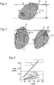
Figs. 1B and 1C present schematic illustrations of some of the many ways in which path engineered particles can be oriented in an ion-conducting composite electrolyte according to the present disclosure; -
Fig. 2 is a detailed schematic illustration of a path-engineered particle for use in ion-conducting composite electrolytes according to the present disclosure; -
Fig. 3 illustrates particles comprising impeded linear ion-conducting paths; -
Fig. 4 illustrates an electrochemical device comprising a cathode and an anode separated by a composite electrolyte; and -
Fig. 5 is a plot of area specific resistance versus membrane thickness. - Referring initially to
Fig. 1A , a portion of an ion-conductingcomposite electrolyte 10 is illustrated schematically and comprises path-engineered ion-conductingceramic electrolyte particles 20, a solidpolymeric matrix 30, and, optionally, afiber stiffener component 40 distributed throughout thepolymeric matrix 30. The respective shapes of the path-engineeredparticles 20 may vary significantly from particle to particle and is not illustrated with particular precision inFig. 1A . Rather, the path-engineeredparticles 20 ofFig. 1A are merely presented to show their presence in thepolymeric matrix 30 and to show that their size and shape will typically vary across thecomposite electrolyte 30. Similarly, the size and shape of the path-engineered particles illustrated inFigs. 1B and 1C , described in further detail below, have been intentionally simplified for illustrative purposes. - As is illustrated in
Fig. 1A , the polymeric matrix defines a pair of oppositemajor faces particles 20 are sized and positioned in thepolymeric matrix 30 such that a majority of the path-engineeredparticles 20 breach, i.e., are flush with or extend beyond, both of the oppositemajor faces - Referring for example to the hexagonal crystalline structures illustrated in
Figs. 1B and 1C , it is contemplated that the path-engineeredparticles 20 can be selected such that they are characterized by an anisotropic crystalline structure. In which case, the particles can be selected such that the ionic conductivity of the crystalline structure in a preferred conductivity direction H associated with one of the crystal planes of the path-engineeredparticle 20 is larger than the ionic conductivity of the crystalline structure in a reduced conductivity direction L associated with a different crystal plane of the path-engineeredparticle 20. In this manner, substantially all, or at least a majority of, the path engineeredparticles 20 can be oriented in thepolymeric matrix 30 such that the preferred conductivity direction H is more closely aligned with a minimum path length x spanning a thickness of the matrix body, i.e., more closely aligned than the reduced conductivity direction L. This alignment is illustrated schematically inFigs. 1B and 1C and can lead to a composite electrolyte with enhanced ionic conductivity, typically on the order of approximately 10-4 S/cm or greater. For example, and not by way of limitation, in the context of lithium-aluminum titanium phosphate (LATP) path-engineeredparticles 20, the ionic conductivity of the crystalline structure in the preferred conductivity direction H is approximately one order of magnitude larger than the ionic conductivity of the crystalline structure in the reduced conductivity direction L. - To encourage the aforementioned orientation, it is contemplated that the path engineered
particles 20 can be sized such that a size dimension of the path-engineeredparticle 20 in the preferred conductivity direction H is smaller than a size dimension of the path-engineeredparticle 20 in the reduced conductivity direction L. The difference in the respective size dimensions of the path-engineeredparticle 20 can be used to encourage self-alignment of the path engineered particles in the aforementioned orientation because, in many of the contemplated fabrication processes described herein a particle will naturally tend to settle in an orientation that is strongly influenced by the relative size dimensions of the particle in different directions. - For path-engineered particles characterized by an isotropic crystalline structure, the aforementioned selective orientation would not typically be necessary. Examples of suitable isotropic crystalline structures include, but are not limited to, lithium ion conductors with the cubic garnet structure such as aluminum-stabilized Li7La3Zr2O12, or with the perovskite structure such as Li3xLa0.67-xTiO3, and typically lead to a composite electrolyte with enhanced ionic conductivity typically on the order of approximately 1x10⁻⁴ S/cm or greater.
- Particular embodiments of the present disclosure relate to the advantageous use of path-engineered
particles 20 that are characterized by hexagonal crystalline structures. More specifically, referring toFig. 1B , in the context of path-engineeredparticles 20 comprising hexagonal crystalline structures, the present inventors have recognized that the ionic conductivity of thecomposite electrolyte 10 can be enhanced by ensuring that a majority, or substantially all, of the path engineeredparticles 20 are oriented in thepolymeric matrix 30 such that the minimum path length x spanning a thickness of the matrix body is more closely aligned with the relatively high conductivity crystallographic direction H than with the relatively low conductivity crystallographic direction L. - Regarding contemplated compositions of path-engineered
particles 20 according to the present disclosure, in particular embodiments, the path-engineeredparticles 20 will comprise an ion-conducting ceramic, such as, for example, a lithium ion-conducting ceramic like LATP or a derivative thereof. Such materials may possess internal inclusions that typically comprise aluminum phosphate, titanium dioxide, aluminum oxide, or combinations thereof. Additional contemplated embodiments will include path engineered particles comprising an ion-conducting ceramic selected from lithium metal phosphates, sodium zirconia phosphates, sodium beta aluminate, fluorites, and ceramic oxides with garnet-type crystalline structures. The composition or choice of material is selected partly based upon the ability to grow crystals by a convenient technique like the Czochralski process. Examples of such materials are LiNbO3, YVO4, Al2O3, and Ce2O3-doped Y3Al5O12 (YAG:Ce). It is noted that the compositional profile of contemplated composite electrolytes can be controlled by doping to attain desired properties. - As is illustrated in
Fig. 2 , it is contemplated that a majority of the face-breaching, path-engineeredparticles 20 may comprise internal inclusions in the form ofprimary inclusions 22 andsecondary phase inclusions 24,grain boundaries 26,pores 28, or combinations thereof. In this context, the path-engineeredparticles 20 can be oriented in thepolymeric matrix 30 to comprise a breaching cross section, examples of which are illustrated schematically inFigs. 1 and2 . The breaching cross section defines a cross-body, linear ion-conducting path (+) that is unimpeded by theinternal inclusions grain boundaries 26, and thepores 28 of theparticle 20. To clarify, by contrast, the linear ion-conducting paths (+) of the particles 20' illustrated inFig. 3 are impeded by the internal inclusions 22', 24', the grain boundaries 26' and the pores 28', and as such are not cross-body, linear ion-conducting paths. By incorporating the aforementioned cross-body, linear ion-conducting path composite electrolytes according to the present disclosure eliminate, or substantially reduce, the impact of grain boundaries on ionic transport. - As is illustrated in the example of
Fig. 2 , it is contemplated that a face-breaching, path-engineeredparticle 20 according to the present disclosure may comprise a single crystal majority, by volume, that is free of grain boundaries, although a remaining volume of the particle itself comprises a minority ofgrain boundaries 26,internal inclusions pores 28. Typically, the remaining volume comprises primary phase inclusions of distinct crystal orientation, secondary phase inclusions, pores, or combinations thereof and occupies between approximately 0.1% and approximately 20%, by volume, of the face-breaching, path-engineeredparticle 20. - It is also contemplated that the aforementioned unimpeded linear ion-conducting paths (+) may be more readily achieved by ensuring that the
grain boundaries 26 of the path engineeredparticles 20 span less than a majority of the breaching cross section of the face-breaching, path-engineered particles in a direction substantially parallel to the major faces of the matrix body. An example of a grain boundary satisfying this condition is illustrated inFig. 2 , while the right-hand side particle 20' illustrated inFig. 3 includes a grain boundary 26' that does not satisfy this condition. - As is further illustrated in
Fig. 2 , preferably, at least a majority of the path-engineeredparticles 20 are oriented in thepolymeric matrix 30 such that respective breaching cross sections of theparticles 20 define a cross-body, linear ion-conducting path that is unimpeded by thesecondary phase inclusions 24,grain boundaries 26, andclosed pores 28 of the face-breaching, path-engineeredparticle 20. - Regarding the volumetric composition of the
composite electrolyte 10, it is contemplated that particular embodiments will comprise (i) between approximately 10% and approximately 95% of the face-breaching, path-engineered particles 20 (ii) between approximately 5% and approximately 90% of thepolymeric matrix 30, and (iii) between approximately 0.1% and approximately 20% of impeded-path ion-conducting ceramic electrolyte particles 20', by volume. For the purposes of defining and describing aspect of the present disclosure, it is noted that impeded-path ion-conducting particles 20' are particles that do not comprise the above-described unimpeded cross-body, linear ion-conducting path, either because they are dominated by inclusions 24', grain boundaries 26', and/or pores 28', are primarily polycrystalline, or do not breach both of the opposite major faces of the matrix body. More preferably, it is contemplated that, in some embodiments, thecomposite electrolyte 10 comprises at least approximately 20% of the face-breaching, path-engineeredparticles 20, by volume. - Regarding the dimensional characteristics of the
composite electrolyte 10, it is contemplated that, in particular embodiments, the path-engineered particles will define an average size (d50) of between approximately 10µm and approximately 1mm with a size dispersion ((d90-d10)/d50) that is less than approximately 1.0. It is also contemplated that thecomposite electrolyte 10 will often advantageously define a thickness of between approximately 10µm and approximately 50µm. It is contemplated that the thickness of a composite electrolyte according to the present disclosure for any given application is a function of its conductivity, mechanical strength, and methods of preparation. It may range from a few microns up to about 1 mm. Within a given composite electrolyte membrane, a narrow dispersion in the size of the path engineeredparticles 20 is preferred. Grains that are too large would protrude far above the surface of the polymer and would potentially interfere with sheet forming processes, assembly, and the like. Particles that are smaller than the thickness of the polymer cannot span the membrane and provide a conductive pathway. Crystalline structures used for the composite electrolytes of the present disclosure need not be regular in shape nor compositionally uniform or free of inclusions. Crystals of the type required for the composite electrolyte can be prepared efficiently by techniques such as prolonged sintering to allow grain growth or by slow cooling from the melt. The product of either process can then be ground and selectively sized by sieving, air-classification, etc. - Methods of preparing ion-conducting
composite electrolytes 10 according to the present disclosure involve preparing the path-engineeredparticles 20 for inclusion in thepolymeric matrix 30 by subjecting ceramic precursor crystals to thermally-induced microcracking. The microcracked precursor crystals can subsequently be separated into individual path-engineered ion-conductingceramic electrolyte particles 20. Thecomposite electrolyte 10 including the path-engineeredparticles 20 and thepolymeric matrix 30 may be assembled by a variety of suitable techniques including, without limitation, injection molding, compression molding, roll molding, film casting, spin coating alone on in conjunction post forming techniques like plasma etching, mechanical abrasion, laser ablation to expose the particles and enable ionic conduction. In some embodiments, contemplated composite electrolyte membranes can be formed by polymer processing techniques without sintering. - For example, and not by way of limitation, relatively large crystals of lithium ion-conducting LATP (Li1.3Al0.3Ti1.7(PO4)3) were prepared by extending sintering. The reactants for the two batches listed in the table below were dry blended in a total amount of about 2 kg each, transferred into platinum crucibles, reacted for 12 hours at 190°C, reacted 12 hours and 800°C to partially form the LATP crystalline structure, and then vibratory milled.
Batch Material Weight Percent 625 EQP 625 EQM L22 - Li2CO3 11.656 - L510 - LiH2PO4 - 33.205 A121 - Al(PO3)3 19.213 19.457 T26-TiO2 32.962 33.383 P4 - P2O5 36.169 13.955 - The milled powder was formed into -25 mm diameter pills by uniaxially pressing. The pills were sintered at temperatures and times listed in Table #2 to induce grain growth.
Sample / Temp / Time Weight Percent of Phase Microtrac PSD (µm) (d90-d10) d50 LiTi2(PO4)3 TiO2 (Rutile) AlPO4 d10 d50 d90 EQM 1150° C 100 hrs97 1.5 2 185 359 530 0.96 EQM 1150° C 150 hrs89 5.2 6.3 74 288 481 1.41 EQM 1150°C 240 hrs 93 1.6 5.4 165 355 535 1.04 EQP 1150° C 100 hrs98 0.7 0.8 126 303 466 1.12 EQP 1150° C 150 hrs94 2.9 3 38 89 257 2.47 EQP 1150°C 240 hrs 96 0.6 3.5 44 102 373 3.23 S-70 Steel Shot 253 318 410 0.49 - The resulting grains are roughly equiaxed and have size determined visually from 300 to more than 1000 µm.
- The grains in the pills were further processed into a powder that is made of particles that are themselves predominantly single crystals. Although it is possible to imagine grinding, jet milling or another high energy technique to separate the particles and reduce their sizes, this was not necessary with LATP. The crystalline structure of LATP is not cubic, and is subject to microcracking as a result of its large thermal expansion anisotropy. The critical grain size for microcracking is estimated to be about 0.5 µm. This critical grain size is almost two orders of magnitude smaller than those obtained by extended sintering. The pills were extensively microcracked and with only the mildest of forces crumbled into individual crystals.
- It is contemplated that relatively large crystals can be achieved through nucleation and growth from a melt. In one example, LATP crystals were grown starting with the reactants listed in the following table:
Batch Material 625 EQT 625 EQU 625 EQV Li1.15Al0.15Ti1.85(PO4)3 Li1.3Al0.3Ti1.7(PO4)3 Li1.4Al0.4Ti1.6(PO4)3 L510 - LiH2PO4 29.418 33.205 35.724 A121 - Al(PO3)3 9.743 19.458 25.918 T26-TiO2 36.382 33.383 31.388 P4 - P2O5 24.457 13.954 6.970 - The resulting raw materials were dry blended, transferred into a platinum crucible, heated at ∼100°C/hr to 1600°C, and then cooled at a rate of 10°C/hr to 100°C. The morphology of the product in the crucibles showed that crystals with size well above 1 mm were obtained by this technique. One would not necessarily predict that an off-stoichiometry composition would crystallize to give a nearly single phase product. For this reason, it is contemplated that the methodology may be applied to LATP or other ionically conducting materials that are disposed for use in a composite electrolyte.
- In one embodiment, spin-coating and chemical etching were applied to produce a composite electrolyte membrane by starting with 4g of a 5:1 PDMS solution, 1 g of 625 EQU ground and sieved to give particles with sizes ranging from 250-355 µm, spin coating at 500 rpm for 10 seconds, and lastly etching both surfaces in a batch of NMB/TBAF for 15 minutes to remove residual silicone. The thickness of the silicone in the as-finished membrane, i.e. between the LATP particles, was about 140 µm, which is significantly thinner than the lithium ion-conducting crystal particles. For a specimen with an active area of 72.4 mm2, the DC resistance of the membrane was taken as approximately 175 Ω. With geometric factors of the electrolyte membrane taken into account, this translates to a lithium ion conductivity of 2.7×10⁻⁴ S/cm, more than four-fold greater than the highest value reported for a polycrystalline sample of the same composition.
- For many forming techniques, a residual overcoat of polymer on the surface of the conducting particles will be an inherent result of the process. This residual is likely to block movement of the mobile ion that the electrolyte carries and degrade conductivity. The residual can be removed by a variety of techniques, including, but not limited to, chemical etching, polishing, mechanical abrasion, refractive ion etching, ozone plasma treatment, and laser ablation.
- Referring to
Fig. 4 , it is noted thatcomposite electrolytes 10 according to the present disclosure provide several parameters that may be adjusted and tailored to improve the performance ofelectrochemical devices 50 incorporating theelectrolyte 10. Contemplated parameters include, but are not limited to average particle size, the dispersion in their size, the conductivity of single crystal components of the particles, their orientation, the thickness of the polymer membrane, and the degree of exposure of the particles beyond the major faces of the polymeric matrix in which they are positioned. These and other parameters may be selected to improve electrochemical performance attributes such as power density or response speed and/or mechanical performance attributes that facilitate handling, in-service durability, or device lifetime. - From an electrochemical perspective, the primary benefits created by a composite electrolyte are a higher ionic conductivity and equivalent or lower area specific resistance (ASR) than what can be achieved in an optimized polycrystalline membrane that conducts the same ionic species. For example, the ionic conductivity within a crystal of doped polycrystalline lithium titanium phosphate and lithium germanium phosphate ceramics is a factor of 50 to 100 times greater than realized in the polycrystalline state as a whole. On average, the single crystal conductivity of these doped titanium and germanium phosphates approaches or exceeds 10-3 S/cm.
- Referring to
Fig. 5 , it is noted that ASR is a key figure of merit used to judge the power generating capability of an electrochemical device or its components, i.e., its electrolyte membrane. The ASR of the electrolyte is the dominant contributor to the total ASR of a device if its conductivity is low and the membrane thickness is large. InFig. 5 , the ASR of a composite electrolyte C based upon single crystals of the composition Li1.3Al0.3Ti1.7(PO3)3 is compared to a sintered polycrystalline electrolyte P of the same composition as a function of membrane thickness x. The figure illustrates two solids loadings, 25% and 50%, of single crystals in the composite electrolyte. It also assumes that the single crystals are flush with the polymer surface, that is to say they do not bulge from the surface of the electrolyte. It is also assumed that the surfaces of the single crystals are fully exposed, i.e. no polymer overcoat, and that the crystals have a uniform cross-section and are oriented normal to the plane of the membrane. Under these conditions, the composite electrolyte even with only a 25% volume loading in the membrane provide an ASR that is a factor of four lower than the polycrystalline electrolyte of the same thickness. The advantage grows larger for the composite electrolyte as the volume loading of single crystals is increased to 50% - It is not necessary to utilize the low ASR of the membrane to improve electrochemical performance. It can be traded for other attributes. For example, the ASR of a polycrystalline electrolyte that is thin may be acceptable from and electrochemical standpoint for application in a device. However, its thin nature might make manufacturing difficult or compromise the durability of the device. The composite electrolyte because of its inherently higher conductivity can be made with an equivalent ASR but with a much greater thickness to overcome such issues. Another possibility is to impart a maximum level of flexibility to the membrane. This can be accomplished by minimizing the amount of single crystal ion conductor within the composite. The ASR calculation represented in
Fig. 5 provides the basis for both of these possibilities. - It is contemplated that composite electrolytes described herein can be the source of numerous advantages with respect to the start of the art. For example, contemplated composite electrolytes are likely to exhibit ionic conductivity that is greater than that which would be available from comparable polycrystalline ceramic electrolytes. Further, contemplated composite electrolyte structures are likely to be more easily handled during processing and device assembly steps and are less likely to be subject to abrupt or unpredictable mechanical failure. The ionic conductivity of contemplated composite electrolyte structures can be traded for increased mechanical integrity by thickening the electrolyte while still maintaining sufficiently high electrochemical performance.
- Although the concepts of the present disclosure are described herein with primary reference to a composite electrolyte structure, it is contemplated that the concepts will enjoy applicability to any device that employs an electrolyte structure. For example, and not by way of limitation, it is contemplated that the concepts of the present disclosure will enjoy applicability to a variety of electrochemical devices including, but not limited to, lithium ion batteries, sodium sulfur batteries, solid oxide fuel cells, oxygen separators, electrolyzers, sensors, chemical reactors, etc. By way of illustration, and not limitation,
Fig. 4 illustrates anelectrochemical device 50 comprising acathode 60 and ananode 70 separated by acomposite electrolyte 10. - It is noted that terms like "preferably," "commonly," and "typically," when utilized herein, are not utilized to limit the scope of the disclosure or to imply that certain features are critical, essential, or even important to the structure or function of the disclosure. Rather, these terms are merely intended to identify particular aspects of an embodiment of the present disclosure or to emphasize alternative or additional features that may or may not be utilized in a particular embodiment of the present disclosure.
- For the purposes of describing and defining the present inventive subject matter it is noted that the terms "substantially" and "approximately" are utilized herein to represent the inherent degree of uncertainty that may be attributed to any quantitative comparison, value, measurement, or other representation. The terms "substantially" and "approximately" are also utilized herein to represent the degree by which a quantitative representation may vary from a stated reference without resulting in a change in the basic function of the subject matter at issue.
- Having described the subject matter of the present disclosure in detail and by reference to specific embodiments thereof, it is noted that the various details disclosed herein should not be taken to imply that these details relate to elements that are essential components of the various embodiments described herein, even in cases where a particular element is illustrated in each of the drawings that accompany the present description. Rather, the claims appended hereto should be taken as the sole representation of the breadth of the present disclosure and the corresponding scope of the various embodiments described herein. Further, it will be apparent that modifications and variations are possible without departing from the scope of the disclosure defined in the appended claims. More specifically, although some aspects of the present disclosure are identified herein as preferred or particularly advantageous, it is contemplated that the present disclosure is not necessarily limited to these aspects.
- It is noted that one or more of the following claims utilize the term "wherein" as a transitional phrase. For the purposes of defining the present inventive subject matter, it is noted that this term is introduced in the claims as an open-ended transitional phrase that is used to introduce a recitation of a series of characteristics of the structure and should be interpreted in like manner as the more commonly used open-ended preamble term "comprising." Aspects of the invention will now be described by way of clauses below:
- Clause 1. An ion-conducting composite electrolyte comprising path-engineered ion-conducting ceramic electrolyte particles and a solid polymeric matrix, wherein:
- the polymeric matrix defines a pair of opposite major faces defining a matrix body there between;
- the path-engineered particles are characterized by an anisotropic crystalline structure comprising a plurality of crystal planes;
- the ionic conductivity of the crystalline structure in a preferred conductivity direction H associated with one of the crystal planes of the path-engineered particle is larger than the ionic conductivity of the crystalline structure in a reduced conductivity direction L associated with another of the crystal planes of the path-engineered particle; and
- the path-engineered particles are sized and positioned in the polymeric matrix such that a majority of the path-engineered particles breach both of the opposite major faces of the matrix body and are oriented in the polymeric matrix such that the preferred conductivity direction H is more closely aligned with a minimum path length x spanning a thickness of the matrix body than is the reduced conductivity direction L.
- Clause 2. An ion-conducting composite electrolyte as claimed in clause 1 wherein the ionic conductivity of the crystalline structure in the preferred conductivity direction H is approximately one order of magnitude larger than the ionic conductivity of the crystalline structure in the reduced conductivity direction L.
- Clause 3. An ion-conducting composite electrolyte as claimed in clause 1 wherein:
- the majority of path engineered particles are sized such that a size dimension of the path-engineered particle in the preferred conductivity direction H is smaller than a size dimension of the path-engineered particle in the reduced conductivity direction L; and
- the difference in the respective size dimensions of the path-engineered particle encourages self-alignment of the path engineered particles in the solid polymeric matrix, where the preferred conductivity direction H is more closely aligned with a minimum path length x spanning a thickness of the matrix body than is the reduced conductivity direction L.
- Clause 4. An ion-conducting composite electrolyte as claimed in clause 1 wherein:
- the path-engineered particles are characterized by a hexagonal crystalline structure;
- the ionic conductivity of the hexagonal crystalline structure in a preferred conductivity direction H lying in the plane of the crystal is larger than the ionic conductivity of the hexagonal crystalline structure in a reduced conductivity direction L normal to the plane of the crystal; and
- a majority of the path engineered particles are oriented in the polymeric matrix such that a minimum path length x spanning a thickness of the matrix body is more closely aligned with the preferred conductivity direction H than with the reduced conductivity direction L.
- Clause 5. An ion-conducting composite electrolyte as claimed in clause 1 wherein:
- the path-engineered particles are characterized by a hexagonal crystalline structure;
- the ionic conductivity of the hexagonal crystalline structure in a preferred conductivity direction H lying in the plane of the crystal is larger than the ionic conductivity of the hexagonal crystalline structure in a reduced conductivity direction L normal to the plane of the crystal; and
- substantially all of the path engineered particles are oriented in the polymeric matrix such that a minimum path length x spanning a thickness of the matrix body is more closely aligned with the preferred conductivity direction H than with the reduced conductivity direction L.
- Clause 6. An ion-conducting composite electrolyte as claimed in clause 1 wherein a majority of the face-breaching, path-engineered particles comprise internal inclusions and grain boundaries and are oriented in the polymeric matrix to comprise a breaching cross section defining a cross-body, linear ion-conducting path that is unimpeded by the secondary phase inclusions and the grain boundaries of the face-breaching, path-engineered particle.
- Clause 7. An ion-conducting composite electrolyte as claimed in clause 1 wherein:
- respective ones of the face-breaching, path-engineered particles comprise a single crystal majority, by volume, in each particle;
- the single crystal majority is free of grain boundaries; and
- a remaining volume of respective ones of the face-breaching, path-engineered particles comprises primary phase inclusions of distinct crystal orientation, secondary phase inclusions, pores, or combinations thereof.
- Clause 8. An ion-conducting composite electrolyte as claimed in clause 1 wherein the grain boundaries span less than a majority of the breaching cross section of the face-breaching, path-engineered particles in a direction substantially parallel to the major faces of the matrix body.
- Clause 9. An ion-conducting composite electrolyte as claimed in clause1 wherein a majority of the face-breaching, path-engineered particles comprise internal inclusions, grain boundaries, and closed pores and are oriented in the polymeric matrix to comprise a breaching cross section defining a cross-body, linear ion-conducting path that is unimpeded by the secondary phase inclusions, the grain boundaries, and the closed pores of the face-breaching, path-engineered particle.
-
Clause 10. An ion-conducting composite electrolyte as claimed in clause 1 wherein the path engineered particles comprise an ion-conducting ceramic. - Clause 11. An ion-conducting composite electrolyte as claimed in clause 1 wherein the path engineered particles comprise a lithium ion-conducting ceramic.
- Clause 12. An ion-conducting composite electrolyte as claimed in clause 11 wherein the lithium ion-conducting ceramic comprises lithium-aluminum titanium phosphate (LATP) or a derivative thereof.
- Clause 13. An ion-conducting composite electrolyte as claimed in clause 12 wherein the internal inclusions comprise inclusions of aluminum phosphate, titanium dioxide, aluminum oxide, or combinations thereof.
- Clause 14. An ion-conducting composite electrolyte as claimed in clause 1 wherein the path engineered particles comprise an ion-conducting ceramic selected from lithium metal phosphates, sodium zirconia phosphates, sodium beta alumina, fluorites, and ceramic oxides with garnet-type crystalline structures.
- Clause 15. An ion-conducting composite electrolyte as claimed in clause 1 wherein the path-engineered ion-conducting ceramic electrolyte particles are sintered.
- Clause 16. An ion-conducting composite electrolyte as claimed in clause 1 wherein the path-engineered particles define an average size (d50) of between approximately 10µm and approximately 1mm with a size dispersion ((d90-d10)/d50) that is less than approximately 1.0.
- Clause 17. An ion-conducting composite electrolyte as claimed in clause 1 wherein the ion-conducting composite electrolyte is characterized by an ionic conductivity that is on the order of approximately 10-4 S/cm or greater.
- Clause 18. An ion-conducting composite electrolyte as claimed in clause 17 wherein the composite electrolyte comprises at least approximately 20% of the face-breaching, path-engineered particles, by volume.
- Clause 19. An ion-conducting composite electrolyte as claimed in clause 1 wherein the composite electrolyte defines a thickness of between approximately 10µm and approximately 50µm.
-
Clause 20. An ion-conducting composite electrolyte as claimed in clause 1 wherein the composite electrolyte further comprises a fiber stiffener component distributed throughout the polymeric matrix. - Clause 21. An ion-conducting composite electrolyte as claimed in clause 1 wherein the composite electrolyte is comprised within a lithium ion battery, a sodium sulfur battery, a solid oxide fuel cell, an oxygen separator, a sensor, a dehydrogenating chemical reactor, or a device comprising a cathode and an anode separated by the composite electrolyte.
-
Clause 22. An ion-conducting composite electrolyte comprising path-engineered ion-conducting ceramic electrolyte particles and a solid polymeric matrix, wherein:- the polymeric matrix defines a pair of opposite major faces defining a matrix body there between;
- the path-engineered particles are characterized by an isotropic crystalline structure comprising a plurality of crystal planes; and
- the path-engineered particles are sized and positioned in the polymeric matrix such that a majority of the path-engineered particles breach both of the opposite major faces of the matrix body.
- Clause 23. A method of preparing an ion-conducting composite electrolyte comprising path-engineered ion-conducting ceramic electrolyte particles and a solid polymeric matrix, wherein:
- the polymeric matrix defines a pair of opposite major faces defining a matrix body there between;
- the path-engineered particles are sized and positioned in the polymeric matrix such that a majority of the path-engineered particles breach both of the opposite major faces of the matrix body;
- the path-engineered particles are characterized by an anisotropic crystalline structure;
- a majority of the face-breaching, path-engineered particles comprise internal inclusions and grain boundaries and are oriented in the polymeric matrix to comprise a breaching cross section defining a cross-body, linear ion-conducting path that is unimpeded by the secondary phase inclusions and the grain boundaries of the face-breaching, path-engineered particle; and
- the method comprises preparing the path-engineered particles for inclusion in the polymeric matrix by subjecting ceramic precursor crystals to thermally-induced microcracking and separating the microcracked precursor crystals into individual path-engineered ion-conducting ceramic electrolyte particles.
-
Clause 24. An ion-conducting composite electrolyte comprising path-engineered ion-conducting ceramic electrolyte particles and a solid polymeric matrix, wherein:- the polymeric matrix defines a pair of opposite major faces defining a matrix body there between;
- the path-engineered particles are sized and positioned in the polymeric matrix such that a majority of the path-engineered particles breach both of the opposite major faces of the matrix body; and
- the ion-conducting composite electrolyte is characterized by an ionic conductivity that is on the order of approximately 10-4 S/cm or greater.
Claims (1)
- A method of preparing an ion-conducting composite electrolyte comprising path-engineered ion-conducting ceramic electrolyte particles and a solid polymeric matrix, wherein:the polymeric matrix defines a pair of opposite major faces defining a matrix body there between;the path-engineered particles are sized and positioned in the polymeric matrix such that a majority of the path-engineered particles breach both of the opposite major faces of the matrix body;the path-engineered particles are characterized by an anisotropic crystalline structure;a majority of the face-breaching, path-engineered particles comprise internal inclusions and grain boundaries and are oriented in the polymeric matrix to comprise a breaching cross section defining a cross-body, linear ion-conducting path that is unimpeded by the secondary phase inclusions and the grain boundaries of the face-breaching, path-engineered particle; andthe method comprises preparing the path-engineered particles for inclusion in the polymeric matrix by subjecting ceramic precursor crystals to thermally-induced microcracking and separating the microcracked precursor crystals into individual path-engineered ion-conducting ceramic electrolyte particles.
Applications Claiming Priority (3)
| Application Number | Priority Date | Filing Date | Title |
|---|---|---|---|
| US13/597,871 US9502729B2 (en) | 2012-08-29 | 2012-08-29 | Ion-conducting composite electrolyte comprising path-engineered particles |
| PCT/US2013/055943 WO2014035753A1 (en) | 2012-08-29 | 2013-08-21 | Ion-conducting composite electrolyte |
| EP13756962.0A EP2891199B1 (en) | 2012-08-29 | 2013-08-21 | Ion-conducting composite electrolyte |
Related Parent Applications (2)
| Application Number | Title | Priority Date | Filing Date |
|---|---|---|---|
| EP13756962.0A Division-Into EP2891199B1 (en) | 2012-08-29 | 2013-08-21 | Ion-conducting composite electrolyte |
| EP13756962.0A Division EP2891199B1 (en) | 2012-08-29 | 2013-08-21 | Ion-conducting composite electrolyte |
Publications (2)
| Publication Number | Publication Date |
|---|---|
| EP3496183A1 true EP3496183A1 (en) | 2019-06-12 |
| EP3496183B1 EP3496183B1 (en) | 2021-07-21 |
Family
ID=49115580
Family Applications (2)
| Application Number | Title | Priority Date | Filing Date |
|---|---|---|---|
| EP13756962.0A Expired - Fee Related EP2891199B1 (en) | 2012-08-29 | 2013-08-21 | Ion-conducting composite electrolyte |
| EP18211516.2A Active EP3496183B1 (en) | 2012-08-29 | 2013-08-21 | Ion-conducting composite electrolyte comprising particles |
Family Applications Before (1)
| Application Number | Title | Priority Date | Filing Date |
|---|---|---|---|
| EP13756962.0A Expired - Fee Related EP2891199B1 (en) | 2012-08-29 | 2013-08-21 | Ion-conducting composite electrolyte |
Country Status (7)
| Country | Link |
|---|---|
| US (1) | US9502729B2 (en) |
| EP (2) | EP2891199B1 (en) |
| JP (2) | JP2015527722A (en) |
| CN (1) | CN104995764B (en) |
| IN (1) | IN2015DN01885A (en) |
| TW (1) | TWI578349B (en) |
| WO (1) | WO2014035753A1 (en) |
Families Citing this family (39)
| Publication number | Priority date | Publication date | Assignee | Title |
|---|---|---|---|---|
| US9905883B2 (en) * | 2013-03-28 | 2018-02-27 | Corning Incorporated | Ceramic electrolyte material comprising a modified polycrystalline lithium metal phosphate |
| KR102443148B1 (en) | 2013-05-15 | 2022-09-13 | 퀀텀스케이프 배터리, 인코포레이티드 | Solid state catholyte or electrolyte for battery |
| US9595399B2 (en) * | 2013-05-20 | 2017-03-14 | Tdk Corporation | Solid-state ion capacitor |
| WO2015086759A1 (en) * | 2013-12-13 | 2015-06-18 | Basf Se | Alkali-ion conducting composite membranes for electronic applications |
| WO2015110333A1 (en) * | 2014-01-23 | 2015-07-30 | Basf Se | Electrochemical cells comprising alkali-ion conducting composite membranes |
| US9520627B2 (en) | 2014-03-06 | 2016-12-13 | International Business Machines Corporation | Ion conducting hybrid membranes |
| US9666852B2 (en) * | 2014-10-02 | 2017-05-30 | Ford Global Technologies, Llc | Composite separator with aligned particles |
| EP3012885B1 (en) * | 2014-10-23 | 2018-08-08 | Sion Power Corporation | Ion-conductive composite for electrochemical cells |
| JP6800844B2 (en) * | 2014-10-23 | 2020-12-16 | シオン・パワー・コーポレーション | Ion conductive composite for electrochemical cells |
| US10381625B2 (en) | 2014-12-19 | 2019-08-13 | Samsung Electronics Co., Ltd. | Composite membrane, preparation method thereof, anode structure including the composite membrane, and lithium secondary battery including the anode structure |
| JP6956641B2 (en) | 2015-06-24 | 2021-11-02 | クアンタムスケイプ バテリー, インク. | Composite electrolyte |
| CN109075388A (en) | 2015-11-24 | 2018-12-21 | 锡安能量公司 | Ionic conduction compound and its associated uses |
| EP3384548A4 (en) | 2015-12-04 | 2019-07-24 | QuantumScape Corporation | Lithium, phosphorus, sulfur, and iodine including electrolyte and catholyte compositions, electrolyte membranes for electrochemical devices, and annealing methods of making these electrolytes and catholytes |
| JP2017183111A (en) * | 2016-03-30 | 2017-10-05 | 旭化成株式会社 | Separator and method of manufacturing the same |
| JP6804221B2 (en) * | 2016-05-30 | 2020-12-23 | 旭化成株式会社 | Solid electrolyte particles |
| EP3504749A4 (en) | 2016-08-29 | 2020-05-06 | QuantumScape Corporation | Catholytes for solid state rechargeable batteries, battery architectures suitable for use with these catholytes, and methods of making and using the same |
| CN107968219A (en) * | 2016-10-19 | 2018-04-27 | 东莞新能源科技有限公司 | Inorganic solid electrolyte film and preparation method thereof and inorganic full-solid battery |
| BR112019012978A2 (en) | 2016-12-21 | 2019-12-31 | Corning Inc | sintering system and sintered articles |
| US20180277909A1 (en) * | 2017-03-22 | 2018-09-27 | Kabushiki Kaisha Toshiba | Composite electrolyte, secondary battery, battery pack and vehicle |
| JP6659639B2 (en) * | 2017-03-22 | 2020-03-04 | 株式会社東芝 | Composite electrolyte, secondary battery, battery pack and vehicle |
| US10559398B2 (en) | 2017-05-15 | 2020-02-11 | International Business Machines Corporation | Composite solid electrolytes for rechargeable energy storage devices |
| CN110785885B (en) | 2017-05-24 | 2023-10-24 | 锡安能量公司 | Ion-conducting compounds and related uses |
| DE102017118310B4 (en) * | 2017-08-11 | 2023-07-27 | Deutsches Zentrum für Luft- und Raumfahrt e.V. | Fiber composite component designed as an electrochemical storage device and method for its production |
| EP3695452A1 (en) | 2017-10-12 | 2020-08-19 | Robert Bosch GmbH | Ceramic-polymer composite single ion conducting thin film electrolyte |
| JP7184509B2 (en) * | 2017-10-25 | 2022-12-06 | トヨタ自動車株式会社 | Separator and non-aqueous electrolyte secondary battery |
| CN108123158B (en) * | 2017-12-29 | 2020-02-21 | 成都新柯力化工科技有限公司 | Low-temperature ceramic electrolyte membrane for solid oxide fuel cell and preparation method thereof |
| US11515556B1 (en) * | 2018-01-22 | 2022-11-29 | North Carolina Agricultural And Technical State University | Solid electrolyte membrane and use thereof in batteries |
| US10971708B2 (en) | 2018-04-23 | 2021-04-06 | International Business Machines Corporation | Release layer for preparation of ion conducting membranes |
| CN108493480A (en) * | 2018-04-28 | 2018-09-04 | 哈尔滨工业大学 | A kind of compound individual particle layer solid electrolyte and preparation method thereof |
| CN109167080B (en) * | 2018-09-12 | 2022-06-14 | 哈尔滨工业大学(威海) | High-voltage lithium thermal battery |
| KR102608245B1 (en) * | 2019-01-21 | 2023-11-29 | 삼성전자주식회사 | Elctrically conductive hybrid membrane, making method thereof, secondary battery and electronic device comprising the same |
| KR20200092099A (en) * | 2019-01-24 | 2020-08-03 | 삼성전자주식회사 | Composite membrane, and lithium secondary battery including the composite membrane |
| CN114514645A (en) * | 2019-10-30 | 2022-05-17 | 富士胶片株式会社 | Lithium ion secondary battery and method for producing same, and solid electrolyte membrane for lithium ion secondary battery and method for producing same |
| JP7451247B2 (en) * | 2020-03-17 | 2024-03-18 | 本田技研工業株式会社 | How to collect lithium ions |
| FR3110028B1 (en) * | 2020-05-07 | 2022-10-14 | Accumulateurs Fixes | Coated sparse particle and its use as an electrolyte in batteries |
| JP7016392B2 (en) * | 2020-08-18 | 2022-02-04 | 旭化成株式会社 | Separator and its manufacturing method |
| CN113488635B (en) * | 2021-05-24 | 2023-01-13 | 长沙矿冶研究院有限责任公司 | Isotropic heat treatment negative electrode material coating method and preparation method of long-cycle negative electrode material |
| JP7050203B1 (en) * | 2021-07-14 | 2022-04-07 | 日本碍子株式会社 | Electrolyte membrane for electrochemical cell, its manufacturing method, and electrochemical cell |
| CN114050313B (en) * | 2021-09-24 | 2022-10-18 | 南京大学 | Inorganic/polymer composite lithium ion sieve membrane and preparation method and application thereof |
Citations (4)
| Publication number | Priority date | Publication date | Assignee | Title |
|---|---|---|---|---|
| EP0948074A2 (en) * | 1998-03-31 | 1999-10-06 | Canon Kabushiki Kaisha | Secondary battery and manufacturing process therefor |
| EP0977296A1 (en) * | 1997-09-03 | 2000-02-02 | Matsushita Electric Industrial Co., Ltd. | Solid electrolytic moldings, electrode moldings, and electrochemical elements |
| EP1615286A1 (en) * | 2004-07-05 | 2006-01-11 | Polymatech Co., Ltd. | Ion conductive polymer electrolyte membrane and production method for the same |
| US20100015494A1 (en) * | 2008-02-26 | 2010-01-21 | University Of Rochester | Ion-Conducting Ceramic Apparatus, Method, Fabrication, and Applications |
Family Cites Families (20)
| Publication number | Priority date | Publication date | Assignee | Title |
|---|---|---|---|---|
| SE339374B (en) | 1966-01-24 | 1971-10-04 | C Forestek | |
| NL6713531A (en) | 1967-10-05 | 1969-04-09 | ||
| US3615841A (en) | 1968-07-31 | 1971-10-26 | Leesona Corp | Electrochemical cell |
| US4183988A (en) | 1978-11-16 | 1980-01-15 | General Electric Company | Solid ion-conductive electrolyte |
| US4247499A (en) | 1979-05-18 | 1981-01-27 | General Electric Company | Methods of forming a solid ion-conductive electrolyte |
| US4977007A (en) | 1986-09-19 | 1990-12-11 | Matsushita Electrical Indust. Co. | Solid electrochemical element and production process therefor |
| JPS6378405A (en) * | 1986-09-19 | 1988-04-08 | 松下電器産業株式会社 | Anisotropic ion conductor |
| US5491039A (en) | 1994-02-04 | 1996-02-13 | Shackle; Dale R. | Solid electrolytes including organometallic ion salts and electrolytic cells produced therefrom |
| JP3788308B2 (en) * | 2001-10-22 | 2006-06-21 | トヨタ自動車株式会社 | ELECTROLYTE MEMBRANE FOR FUEL CELL AND FUEL CELL HAVING THE SAME |
| CN101040401A (en) * | 2004-08-17 | 2007-09-19 | 株式会社小原 | Lithium ion secondary battery and a solid electrolyte thereof |
| CA2574304C (en) * | 2004-08-18 | 2011-09-13 | Central Research Institute Of Electric Power Industry | Solid polymer electrolyte battery and method for manufacturing positive electrode sheet used therein |
| CN100539288C (en) * | 2004-12-02 | 2009-09-09 | 株式会社小原 | All solid state type lithium rechargeable battery and solid electrolyte thereof |
| US7820022B2 (en) | 2005-11-28 | 2010-10-26 | General Electric Company | Photoelectrochemical cell and method of manufacture |
| JP2008021416A (en) * | 2006-07-10 | 2008-01-31 | Idemitsu Kosan Co Ltd | Solid electrolyte sheet |
| CN105655519B (en) * | 2007-06-01 | 2020-10-02 | 达拉米克有限责任公司 | Lead acid battery separator with enhanced stiffness |
| WO2009070600A2 (en) * | 2007-11-27 | 2009-06-04 | Ceramatec, Inc. | Substantially solid, flexible electrolyte for alkili-metal-ion batteries |
| JP2009181807A (en) * | 2008-01-30 | 2009-08-13 | Sony Corp | Solid electrolyte, solid electrolyte battery, manufacturing method of lithium ion conductor, manufacturing method of solid electrolyte, and manufacturing method of solid electrolyte battery |
| DE102011003746B4 (en) * | 2011-02-08 | 2017-12-28 | Fraunhofer-Gesellschaft zur Förderung der angewandten Forschung e.V. | Ion-conducting solid-state separator and its production and use |
| US9287540B2 (en) * | 2011-05-31 | 2016-03-15 | GM Global Technology Operations LLC | Separators for a lithium ion battery |
| US20130052509A1 (en) * | 2011-08-25 | 2013-02-28 | GM Global Technology Operations LLC | Lithium ion battery with electrolyte-embedded separator particles |
-
2012
- 2012-08-29 US US13/597,871 patent/US9502729B2/en active Active
-
2013
- 2013-08-21 EP EP13756962.0A patent/EP2891199B1/en not_active Expired - Fee Related
- 2013-08-21 CN CN201380053856.9A patent/CN104995764B/en active Active
- 2013-08-21 EP EP18211516.2A patent/EP3496183B1/en active Active
- 2013-08-21 JP JP2015529864A patent/JP2015527722A/en active Pending
- 2013-08-21 WO PCT/US2013/055943 patent/WO2014035753A1/en unknown
- 2013-08-21 IN IN1885DEN2015 patent/IN2015DN01885A/en unknown
- 2013-08-28 TW TW102130870A patent/TWI578349B/en not_active IP Right Cessation
-
2018
- 2018-01-05 JP JP2018000614A patent/JP6496048B2/en not_active Expired - Fee Related
Patent Citations (4)
| Publication number | Priority date | Publication date | Assignee | Title |
|---|---|---|---|---|
| EP0977296A1 (en) * | 1997-09-03 | 2000-02-02 | Matsushita Electric Industrial Co., Ltd. | Solid electrolytic moldings, electrode moldings, and electrochemical elements |
| EP0948074A2 (en) * | 1998-03-31 | 1999-10-06 | Canon Kabushiki Kaisha | Secondary battery and manufacturing process therefor |
| EP1615286A1 (en) * | 2004-07-05 | 2006-01-11 | Polymatech Co., Ltd. | Ion conductive polymer electrolyte membrane and production method for the same |
| US20100015494A1 (en) * | 2008-02-26 | 2010-01-21 | University Of Rochester | Ion-Conducting Ceramic Apparatus, Method, Fabrication, and Applications |
Also Published As
| Publication number | Publication date |
|---|---|
| CN104995764B (en) | 2017-03-01 |
| JP6496048B2 (en) | 2019-04-03 |
| JP2018085343A (en) | 2018-05-31 |
| EP2891199A1 (en) | 2015-07-08 |
| EP2891199B1 (en) | 2019-01-23 |
| JP2015527722A (en) | 2015-09-17 |
| WO2014035753A1 (en) | 2014-03-06 |
| TWI578349B (en) | 2017-04-11 |
| EP3496183B1 (en) | 2021-07-21 |
| TW201411667A (en) | 2014-03-16 |
| US20140065513A1 (en) | 2014-03-06 |
| IN2015DN01885A (en) | 2015-08-07 |
| US9502729B2 (en) | 2016-11-22 |
| CN104995764A (en) | 2015-10-21 |
Similar Documents
| Publication | Publication Date | Title |
|---|---|---|
| EP3496183B1 (en) | Ion-conducting composite electrolyte comprising particles | |
| US11424480B2 (en) | Lithium-ion-conducting composite material and process for producing | |
| US20220190382A1 (en) | Annealed garnet electrolyte separators | |
| CN109980182B (en) | Method for producing electrode, and electrode-electrolyte layer assembly | |
| US7211532B2 (en) | Alkali ion conductive glass-ceramics and electric cells and gas sensors using the same | |
| JP4940080B2 (en) | Lithium ion conductive solid electrolyte and method for producing the same | |
| US7618731B2 (en) | Ceramic-ceramic nanocomposite electrolyte | |
| CN109564791B (en) | Solid electrolyte and all-solid-state battery | |
| US10033066B2 (en) | Solid electrolyte and method of manufacturing solid electrolyte | |
| JP5234933B2 (en) | Method for producing lithium ion conductive solid electrolyte | |
| KR101537067B1 (en) | Solid electrolyte for all solid state rechargeable lithium battery, method for preparing the same, and all solid state rechargeable lithium battery including the same | |
| JP5306663B2 (en) | Laminate for lithium ion secondary battery and method for producing the same | |
| US20190165414A1 (en) | Methods for lowering the hot-pressing temperatures of garnet structured ionic conductors | |
| CN111056839A (en) | Boron compound doped lithium lanthanum zirconium oxygen solid electrolyte and preparation method thereof | |
| WO2021215403A1 (en) | Lithium ion-conductive glass ceramic | |
| EP1028094B1 (en) | Lithium ion conductive glass-ceramics and electric cells and gas sensors using the same | |
| KR102206961B1 (en) | Solid electrolyte, method for manufacturing the same, and all solid state rechargeable lithium battery including the same | |
| JP6701393B2 (en) | Solid electrolyte and method for producing solid electrolyte | |
| Chaurasia et al. | Hybrid Organic-Inorganic Polymer Composites | |
| WO2021106775A2 (en) | Garnet-type lithium solid electrolyte material and battery | |
| Wätzig et al. | Lithium loss indicated formation of microcracks in LATP ceramics | |
| KR101661523B1 (en) | Solid electrolyte, method for manufacturing the same, and all solid state rechargeable lithium battery including the same | |
| KR20230051269A (en) | Positive electrode active material and lithium ion secondary battery |
Legal Events
| Date | Code | Title | Description |
|---|---|---|---|
| PUAI | Public reference made under article 153(3) epc to a published international application that has entered the european phase |
Free format text: ORIGINAL CODE: 0009012 |
|
| STAA | Information on the status of an ep patent application or granted ep patent |
Free format text: STATUS: THE APPLICATION HAS BEEN PUBLISHED |
|
| AC | Divisional application: reference to earlier application |
Ref document number: 2891199 Country of ref document: EP Kind code of ref document: P |
|
| AK | Designated contracting states |
Kind code of ref document: A1 Designated state(s): AL AT BE BG CH CY CZ DE DK EE ES FI FR GB GR HR HU IE IS IT LI LT LU LV MC MK MT NL NO PL PT RO RS SE SI SK SM TR |
|
| STAA | Information on the status of an ep patent application or granted ep patent |
Free format text: STATUS: REQUEST FOR EXAMINATION WAS MADE |
|
| 17P | Request for examination filed |
Effective date: 20191211 |
|
| RBV | Designated contracting states (corrected) |
Designated state(s): AL AT BE BG CH CY CZ DE DK EE ES FI FR GB GR HR HU IE IS IT LI LT LU LV MC MK MT NL NO PL PT RO RS SE SI SK SM TR |
|
| REG | Reference to a national code |
Ref country code: DE Ref legal event code: R079 Ref document number: 602013078497 Country of ref document: DE Free format text: PREVIOUS MAIN CLASS: H01M0002160000 Ipc: H01M0010056000 |
|
| GRAP | Despatch of communication of intention to grant a patent |
Free format text: ORIGINAL CODE: EPIDOSNIGR1 |
|
| STAA | Information on the status of an ep patent application or granted ep patent |
Free format text: STATUS: GRANT OF PATENT IS INTENDED |
|
| RIC1 | Information provided on ipc code assigned before grant |
Ipc: H01M 8/02 20160101ALI20210111BHEP Ipc: H01M 50/431 20210101ALI20210111BHEP Ipc: H01M 6/18 20060101ALI20210111BHEP Ipc: H01G 11/56 20130101ALI20210111BHEP Ipc: H01M 10/056 20100101AFI20210111BHEP Ipc: H01M 8/10 20160101ALI20210111BHEP Ipc: C08J 5/22 20060101ALI20210111BHEP Ipc: H01M 50/446 20210101ALI20210111BHEP Ipc: C25B 13/04 20210101ALI20210111BHEP Ipc: H01M 8/1048 20160101ALI20210111BHEP Ipc: C25B 13/08 20060101ALI20210111BHEP Ipc: H01M 10/39 20060101ALI20210111BHEP Ipc: H01M 10/0525 20100101ALI20210111BHEP |
|
| INTG | Intention to grant announced |
Effective date: 20210204 |
|
| GRAS | Grant fee paid |
Free format text: ORIGINAL CODE: EPIDOSNIGR3 |
|
| GRAA | (expected) grant |
Free format text: ORIGINAL CODE: 0009210 |
|
| STAA | Information on the status of an ep patent application or granted ep patent |
Free format text: STATUS: THE PATENT HAS BEEN GRANTED |
|
| AC | Divisional application: reference to earlier application |
Ref document number: 2891199 Country of ref document: EP Kind code of ref document: P |
|
| AK | Designated contracting states |
Kind code of ref document: B1 Designated state(s): AL AT BE BG CH CY CZ DE DK EE ES FI FR GB GR HR HU IE IS IT LI LT LU LV MC MK MT NL NO PL PT RO RS SE SI SK SM TR |
|
| REG | Reference to a national code |
Ref country code: GB Ref legal event code: FG4D |
|
| REG | Reference to a national code |
Ref country code: CH Ref legal event code: EP |
|
| REG | Reference to a national code |
Ref country code: DE Ref legal event code: R096 Ref document number: 602013078497 Country of ref document: DE |
|
| REG | Reference to a national code |
Ref country code: AT Ref legal event code: REF Ref document number: 1413433 Country of ref document: AT Kind code of ref document: T Effective date: 20210815 |
|
| REG | Reference to a national code |
Ref country code: IE Ref legal event code: FG4D |
|
| PGFP | Annual fee paid to national office [announced via postgrant information from national office to epo] |
Ref country code: FR Payment date: 20210831 Year of fee payment: 9 |
|
| REG | Reference to a national code |
Ref country code: LT Ref legal event code: MG9D |
|
| REG | Reference to a national code |
Ref country code: NL Ref legal event code: MP Effective date: 20210721 |
|
| PGFP | Annual fee paid to national office [announced via postgrant information from national office to epo] |
Ref country code: DE Payment date: 20210812 Year of fee payment: 9 |
|
| REG | Reference to a national code |
Ref country code: AT Ref legal event code: MK05 Ref document number: 1413433 Country of ref document: AT Kind code of ref document: T Effective date: 20210721 |
|
| PG25 | Lapsed in a contracting state [announced via postgrant information from national office to epo] |
Ref country code: HR Free format text: LAPSE BECAUSE OF FAILURE TO SUBMIT A TRANSLATION OF THE DESCRIPTION OR TO PAY THE FEE WITHIN THE PRESCRIBED TIME-LIMIT Effective date: 20210721 Ref country code: ES Free format text: LAPSE BECAUSE OF FAILURE TO SUBMIT A TRANSLATION OF THE DESCRIPTION OR TO PAY THE FEE WITHIN THE PRESCRIBED TIME-LIMIT Effective date: 20210721 Ref country code: FI Free format text: LAPSE BECAUSE OF FAILURE TO SUBMIT A TRANSLATION OF THE DESCRIPTION OR TO PAY THE FEE WITHIN THE PRESCRIBED TIME-LIMIT Effective date: 20210721 Ref country code: RS Free format text: LAPSE BECAUSE OF FAILURE TO SUBMIT A TRANSLATION OF THE DESCRIPTION OR TO PAY THE FEE WITHIN THE PRESCRIBED TIME-LIMIT Effective date: 20210721 Ref country code: SE Free format text: LAPSE BECAUSE OF FAILURE TO SUBMIT A TRANSLATION OF THE DESCRIPTION OR TO PAY THE FEE WITHIN THE PRESCRIBED TIME-LIMIT Effective date: 20210721 Ref country code: LT Free format text: LAPSE BECAUSE OF FAILURE TO SUBMIT A TRANSLATION OF THE DESCRIPTION OR TO PAY THE FEE WITHIN THE PRESCRIBED TIME-LIMIT Effective date: 20210721 Ref country code: AT Free format text: LAPSE BECAUSE OF FAILURE TO SUBMIT A TRANSLATION OF THE DESCRIPTION OR TO PAY THE FEE WITHIN THE PRESCRIBED TIME-LIMIT Effective date: 20210721 Ref country code: BG Free format text: LAPSE BECAUSE OF FAILURE TO SUBMIT A TRANSLATION OF THE DESCRIPTION OR TO PAY THE FEE WITHIN THE PRESCRIBED TIME-LIMIT Effective date: 20211021 Ref country code: NO Free format text: LAPSE BECAUSE OF FAILURE TO SUBMIT A TRANSLATION OF THE DESCRIPTION OR TO PAY THE FEE WITHIN THE PRESCRIBED TIME-LIMIT Effective date: 20211021 Ref country code: NL Free format text: LAPSE BECAUSE OF FAILURE TO SUBMIT A TRANSLATION OF THE DESCRIPTION OR TO PAY THE FEE WITHIN THE PRESCRIBED TIME-LIMIT Effective date: 20210721 Ref country code: PT Free format text: LAPSE BECAUSE OF FAILURE TO SUBMIT A TRANSLATION OF THE DESCRIPTION OR TO PAY THE FEE WITHIN THE PRESCRIBED TIME-LIMIT Effective date: 20211122 |
|
| PG25 | Lapsed in a contracting state [announced via postgrant information from national office to epo] |
Ref country code: PL Free format text: LAPSE BECAUSE OF FAILURE TO SUBMIT A TRANSLATION OF THE DESCRIPTION OR TO PAY THE FEE WITHIN THE PRESCRIBED TIME-LIMIT Effective date: 20210721 Ref country code: LV Free format text: LAPSE BECAUSE OF FAILURE TO SUBMIT A TRANSLATION OF THE DESCRIPTION OR TO PAY THE FEE WITHIN THE PRESCRIBED TIME-LIMIT Effective date: 20210721 Ref country code: GR Free format text: LAPSE BECAUSE OF FAILURE TO SUBMIT A TRANSLATION OF THE DESCRIPTION OR TO PAY THE FEE WITHIN THE PRESCRIBED TIME-LIMIT Effective date: 20211022 |
|
| REG | Reference to a national code |
Ref country code: CH Ref legal event code: PL |
|
| REG | Reference to a national code |
Ref country code: DE Ref legal event code: R097 Ref document number: 602013078497 Country of ref document: DE Ref country code: BE Ref legal event code: MM Effective date: 20210831 |
|
| PG25 | Lapsed in a contracting state [announced via postgrant information from national office to epo] |
Ref country code: LI Free format text: LAPSE BECAUSE OF NON-PAYMENT OF DUE FEES Effective date: 20210831 Ref country code: DK Free format text: LAPSE BECAUSE OF FAILURE TO SUBMIT A TRANSLATION OF THE DESCRIPTION OR TO PAY THE FEE WITHIN THE PRESCRIBED TIME-LIMIT Effective date: 20210721 Ref country code: CH Free format text: LAPSE BECAUSE OF NON-PAYMENT OF DUE FEES Effective date: 20210831 |
|
| PLBE | No opposition filed within time limit |
Free format text: ORIGINAL CODE: 0009261 |
|
| STAA | Information on the status of an ep patent application or granted ep patent |
Free format text: STATUS: NO OPPOSITION FILED WITHIN TIME LIMIT |
|
| PG25 | Lapsed in a contracting state [announced via postgrant information from national office to epo] |
Ref country code: SM Free format text: LAPSE BECAUSE OF FAILURE TO SUBMIT A TRANSLATION OF THE DESCRIPTION OR TO PAY THE FEE WITHIN THE PRESCRIBED TIME-LIMIT Effective date: 20210721 Ref country code: SK Free format text: LAPSE BECAUSE OF FAILURE TO SUBMIT A TRANSLATION OF THE DESCRIPTION OR TO PAY THE FEE WITHIN THE PRESCRIBED TIME-LIMIT Effective date: 20210721 Ref country code: RO Free format text: LAPSE BECAUSE OF FAILURE TO SUBMIT A TRANSLATION OF THE DESCRIPTION OR TO PAY THE FEE WITHIN THE PRESCRIBED TIME-LIMIT Effective date: 20210721 Ref country code: MC Free format text: LAPSE BECAUSE OF FAILURE TO SUBMIT A TRANSLATION OF THE DESCRIPTION OR TO PAY THE FEE WITHIN THE PRESCRIBED TIME-LIMIT Effective date: 20210721 Ref country code: LU Free format text: LAPSE BECAUSE OF NON-PAYMENT OF DUE FEES Effective date: 20210821 Ref country code: EE Free format text: LAPSE BECAUSE OF FAILURE TO SUBMIT A TRANSLATION OF THE DESCRIPTION OR TO PAY THE FEE WITHIN THE PRESCRIBED TIME-LIMIT Effective date: 20210721 Ref country code: CZ Free format text: LAPSE BECAUSE OF FAILURE TO SUBMIT A TRANSLATION OF THE DESCRIPTION OR TO PAY THE FEE WITHIN THE PRESCRIBED TIME-LIMIT Effective date: 20210721 Ref country code: AL Free format text: LAPSE BECAUSE OF FAILURE TO SUBMIT A TRANSLATION OF THE DESCRIPTION OR TO PAY THE FEE WITHIN THE PRESCRIBED TIME-LIMIT Effective date: 20210721 |
|
| 26N | No opposition filed |
Effective date: 20220422 |
|
| GBPC | Gb: european patent ceased through non-payment of renewal fee |
Effective date: 20211021 |
|
| PG25 | Lapsed in a contracting state [announced via postgrant information from national office to epo] |
Ref country code: IT Free format text: LAPSE BECAUSE OF FAILURE TO SUBMIT A TRANSLATION OF THE DESCRIPTION OR TO PAY THE FEE WITHIN THE PRESCRIBED TIME-LIMIT Effective date: 20210721 Ref country code: IE Free format text: LAPSE BECAUSE OF NON-PAYMENT OF DUE FEES Effective date: 20210821 Ref country code: GB Free format text: LAPSE BECAUSE OF NON-PAYMENT OF DUE FEES Effective date: 20211021 Ref country code: BE Free format text: LAPSE BECAUSE OF NON-PAYMENT OF DUE FEES Effective date: 20210831 |
|
| REG | Reference to a national code |
Ref country code: DE Ref legal event code: R119 Ref document number: 602013078497 Country of ref document: DE |
|
| PG25 | Lapsed in a contracting state [announced via postgrant information from national office to epo] |
Ref country code: CY Free format text: LAPSE BECAUSE OF FAILURE TO SUBMIT A TRANSLATION OF THE DESCRIPTION OR TO PAY THE FEE WITHIN THE PRESCRIBED TIME-LIMIT Effective date: 20210721 |
|
| PG25 | Lapsed in a contracting state [announced via postgrant information from national office to epo] |
Ref country code: HU Free format text: LAPSE BECAUSE OF FAILURE TO SUBMIT A TRANSLATION OF THE DESCRIPTION OR TO PAY THE FEE WITHIN THE PRESCRIBED TIME-LIMIT; INVALID AB INITIO Effective date: 20130821 Ref country code: FR Free format text: LAPSE BECAUSE OF NON-PAYMENT OF DUE FEES Effective date: 20220831 Ref country code: DE Free format text: LAPSE BECAUSE OF NON-PAYMENT OF DUE FEES Effective date: 20230301 |
|
| PG25 | Lapsed in a contracting state [announced via postgrant information from national office to epo] |
Ref country code: MK Free format text: LAPSE BECAUSE OF FAILURE TO SUBMIT A TRANSLATION OF THE DESCRIPTION OR TO PAY THE FEE WITHIN THE PRESCRIBED TIME-LIMIT Effective date: 20210721 |