EP3495739A1 - Cooking device comprising a bezel coupling system with better alignment of knobs and method of assembling such a device - Google Patents
Cooking device comprising a bezel coupling system with better alignment of knobs and method of assembling such a device Download PDFInfo
- Publication number
- EP3495739A1 EP3495739A1 EP18211796.0A EP18211796A EP3495739A1 EP 3495739 A1 EP3495739 A1 EP 3495739A1 EP 18211796 A EP18211796 A EP 18211796A EP 3495739 A1 EP3495739 A1 EP 3495739A1
- Authority
- EP
- European Patent Office
- Prior art keywords
- frame
- plate
- rod
- cooking device
- contact region
- Prior art date
- Legal status (The legal status is an assumption and is not a legal conclusion. Google has not performed a legal analysis and makes no representation as to the accuracy of the status listed.)
- Granted
Links
Images

Classifications
-
- F—MECHANICAL ENGINEERING; LIGHTING; HEATING; WEAPONS; BLASTING
- F24—HEATING; RANGES; VENTILATING
- F24C—DOMESTIC STOVES OR RANGES ; DETAILS OF DOMESTIC STOVES OR RANGES, OF GENERAL APPLICATION
- F24C3/00—Stoves or ranges for gaseous fuels
- F24C3/12—Arrangement or mounting of control or safety devices
-
- F—MECHANICAL ENGINEERING; LIGHTING; HEATING; WEAPONS; BLASTING
- F24—HEATING; RANGES; VENTILATING
- F24C—DOMESTIC STOVES OR RANGES ; DETAILS OF DOMESTIC STOVES OR RANGES, OF GENERAL APPLICATION
- F24C3/00—Stoves or ranges for gaseous fuels
- F24C3/12—Arrangement or mounting of control or safety devices
- F24C3/124—Control panels
-
- B—PERFORMING OPERATIONS; TRANSPORTING
- B23—MACHINE TOOLS; METAL-WORKING NOT OTHERWISE PROVIDED FOR
- B23P—METAL-WORKING NOT OTHERWISE PROVIDED FOR; COMBINED OPERATIONS; UNIVERSAL MACHINE TOOLS
- B23P19/00—Machines for simply fitting together or separating metal parts or objects, or metal and non-metal parts, whether or not involving some deformation; Tools or devices therefor so far as not provided for in other classes
- B23P19/04—Machines for simply fitting together or separating metal parts or objects, or metal and non-metal parts, whether or not involving some deformation; Tools or devices therefor so far as not provided for in other classes for assembling or disassembling parts
-
- F—MECHANICAL ENGINEERING; LIGHTING; HEATING; WEAPONS; BLASTING
- F24—HEATING; RANGES; VENTILATING
- F24C—DOMESTIC STOVES OR RANGES ; DETAILS OF DOMESTIC STOVES OR RANGES, OF GENERAL APPLICATION
- F24C3/00—Stoves or ranges for gaseous fuels
- F24C3/12—Arrangement or mounting of control or safety devices
- F24C3/126—Arrangement or mounting of control or safety devices on ranges
-
- G—PHYSICS
- G05—CONTROLLING; REGULATING
- G05G—CONTROL DEVICES OR SYSTEMS INSOFAR AS CHARACTERISED BY MECHANICAL FEATURES ONLY
- G05G1/00—Controlling members, e.g. knobs or handles; Assemblies or arrangements thereof; Indicating position of controlling members
- G05G1/08—Controlling members for hand actuation by rotary movement, e.g. hand wheels
-
- C—CHEMISTRY; METALLURGY
- C10—PETROLEUM, GAS OR COKE INDUSTRIES; TECHNICAL GASES CONTAINING CARBON MONOXIDE; FUELS; LUBRICANTS; PEAT
- C10L—FUELS NOT OTHERWISE PROVIDED FOR; NATURAL GAS; SYNTHETIC NATURAL GAS OBTAINED BY PROCESSES NOT COVERED BY SUBCLASSES C10G OR C10K; LIQUIFIED PETROLEUM GAS; USE OF ADDITIVES TO FUELS OR FIRES; FIRE-LIGHTERS
- C10L11/00—Fire-lighters
-
- C—CHEMISTRY; METALLURGY
- C10—PETROLEUM, GAS OR COKE INDUSTRIES; TECHNICAL GASES CONTAINING CARBON MONOXIDE; FUELS; LUBRICANTS; PEAT
- C10L—FUELS NOT OTHERWISE PROVIDED FOR; NATURAL GAS; SYNTHETIC NATURAL GAS OBTAINED BY PROCESSES NOT COVERED BY SUBCLASSES C10G OR C10K; LIQUIFIED PETROLEUM GAS; USE OF ADDITIVES TO FUELS OR FIRES; FIRE-LIGHTERS
- C10L11/00—Fire-lighters
- C10L11/08—Apparatus therefor
-
- F—MECHANICAL ENGINEERING; LIGHTING; HEATING; WEAPONS; BLASTING
- F24—HEATING; RANGES; VENTILATING
- F24B—DOMESTIC STOVES OR RANGES FOR SOLID FUELS; IMPLEMENTS FOR USE IN CONNECTION WITH STOVES OR RANGES
- F24B1/00—Stoves or ranges
- F24B1/20—Ranges
-
- F—MECHANICAL ENGINEERING; LIGHTING; HEATING; WEAPONS; BLASTING
- F24—HEATING; RANGES; VENTILATING
- F24B—DOMESTIC STOVES OR RANGES FOR SOLID FUELS; IMPLEMENTS FOR USE IN CONNECTION WITH STOVES OR RANGES
- F24B5/00—Combustion-air or flue-gas circulation in or around stoves or ranges
-
- F—MECHANICAL ENGINEERING; LIGHTING; HEATING; WEAPONS; BLASTING
- F24—HEATING; RANGES; VENTILATING
- F24C—DOMESTIC STOVES OR RANGES ; DETAILS OF DOMESTIC STOVES OR RANGES, OF GENERAL APPLICATION
- F24C3/00—Stoves or ranges for gaseous fuels
Definitions
- This disclosure relates to a cooking device equipped with a surface provided with burner control knobs.
- the burner control knobs are provided with frame-plates shaped in a manner that allows easy alignment and assembly.
- home cooking devices particularly regular stoves and cooktop devices, are provided with burners connected to gas flow control valves that allow a user to control the flames in the burners.
- the cooking devices are also provided with structures offering services that may be a hot panel or cooktop, comprising knobs that interact with the gas flow control valves, generally in a rotational manner, thus ensuring easier interaction with the user.
- the knobs are usually provided with frame-plates arrayed between the actual knob and the hot panel or cooktop of the device for aesthetic purposes, particularly to cover any gaps between the knob and the actual structure of the hot panel or cooktop.
- frame-plates are assembled in a manner whereby they are aligned with the knobs, which may be challenging on a large scale.
- the cooking device which comprises a structure provided with a surface comprising at least one opening; at least one gas flow control valve comprising a rod that extends through an opening in the said surface; at least one knob arrayed on the said surface in a manner whereby it functions in cooperation with the said rod; a frame-plate arrayed between the said knob and the said surface, wherein the said frame-plate comprises a central orifice through which the said rod passes; and wherein the said frame-plate is maybe rotated around the said rod and is slotted in through interference with the said structure provided with a surface.
- the device additionally comprises a gap separating the frame-plate and the structure provided with a surface, that allows offsets any misalignment between the said rod and the said surface.
- the structure provided with a surface is a hot panel.
- the structure provided with a surface is a cooktop.
- aspects of the present disclosure relate to assembling the frame-plates in an aligned manner between the knobs and the hot panels or cooktops on cooking devices. Aspects of the present disclosure relate to providing a cooking device whose components allow aligned assembly of the frame-plates between the knobs and the hot panels or cooktops, particularly on a large scale.
- the present disclosure refers to a cooking device equipped with a specific construct that allows aligned assembly of the frame-plates between the knobs and the hot panels or cooktops on cooking devices, particularly on a large scale.
- the cooking device of the present disclosure comprises a structure 1 provided with a surface 2 that comprises at least one opening 3 (shown in FIG. 5 ), corresponding to the ideal positioning for each knob 5.
- the structure 1 provided with a surface 2 may be either a hot panel or the actual cooktop of the cooking device.
- the cooking device includes at least one gas flow control valve, which allows the user to control flames in burners of the cooking device.
- Each gas flow control valve comprises a rod 4 that extends through the opening 3 of the surface 2.
- the rod 4 works in cooperation with the knob 5 arrayed on the surface 2, whereby it allows interaction between a user and a desired burner flame control.
- the cooking device also includes a frame-plate 6, also referred to as a bezel, arrayed between the knob 5 and the surface 2, whereby it completely covers the openings 3 in the surface 2 and provides an aesthetic benefit for the cooking device.
- a frame-plate 6, also referred to as a bezel arrayed between the knob 5 and the surface 2, whereby it completely covers the openings 3 in the surface 2 and provides an aesthetic benefit for the cooking device.
- the frame-plate 6 includes a central orifice 7 that allows the passage of the rod 4 of the gas flow control valve, being particularly rotatable around the rod 4 and slotting through interference onto the structure 1 provided with the surface 2.
- the central orifice 7 can fit tightly around the rod 4, whereby there is little space for misalignment.
- the cooking device includes a separation gap 8 between the frame-plate 6 and the structure 1 provided with the surface 2, that can offset any misalignment between the rod 4 and the opening 3 on the surface 2.
- the frame-plate 6 also includes at least one geometry 10, that can have an S-shape, that interacts with a second contact region 12 of the structure 1 provided with the surface 2. This interaction ensures a tight snap-fit connection, as indicated by an audible "click” that prevents the displacement or even the removal of the frame-plate 6 by the user after assembly.
- a method of mounting a frame-plate to a surface of a cooking device including: providing said cooking device having at least one burner and a gas flow valve, said gas flow valve including a rod extending through an opening in said surface, providing said frame-plate having a central orifice and at least one protuberance, passing the rod through the central orifice of the frame-plate, slotting the at least one protuberance through the opening in said surface, and rotating the frame-plate about the rod to engage the at least one protuberance with a first contact region of said surface, wherein rotation of said frame-plate about the rod assembles said frame-plate relative to said surface through an interference fit.
- Additional aspects of the method of mounting a frame-plate to a surface of a cooking which can be used alone or in combination with one or more of the other aspects include: rotating said frame-plate about the rod and engaging a second contact region of said surface through a snap-fit connection; providing said frame-plate with at least one geometry configured to engage the second contact region of said surface through a snap-fit connection; rotating said frame-plate about the rod until an audible "click" is produced; providing said structure including said surface, wherein said structure is one of a hot panel or a cooktop; and/or placing a knob on the rod with said frame-plate arrayed between the knob and said surface and configuring the knob to cooperate with the rod to control the at least one burner.
- a frame-plate for mounting a knob to a surface of a cooking device, the cooking device including at least one burner and a gas flow valve, the gas flow valve including a rod that cooperates with the knob to control the at least one burner, the frame plate comprising: a central orifice configured to allow passage of the rod through the frame-plate, wherein the frame plate is rotatable about the rod, at least one protuberance configured to be slotted through a corresponding opening provided in said surface and to engage a first contact region of said surface through an interference fit when said frame-plate is rotated about the rod, and at least one geometry configured to engage a second contact region of said surface through a snap-fit connection when said frame-plate is rotated about the rod.
- the at least one geometry can be configured to provide an audible "click" to indicate when the at least one geometry engages the second contact region of said surface; said frame-plate includes a pair of protuberances and a pair of geometries; the at least one geometry prevents at least one of a removal and displacement of said frame-plate by a user when the at least one geometry engages the second contact region of said surface; and/or the at least one geometry includes an S-shape.
- operably coupled in all of its forms, couple, coupling, coupled, etc. generally means the joining of two components (electrical or mechanical) directly or indirectly to one another. Such joining may be stationary in nature or movable in nature. Such joining may be achieved with the two components (electrical or mechanical) and any additional intermediate members being integrally formed as a single unitary body with one another or with the two components. Such joining may be permanent in nature or may be removable or releasable in nature unless otherwise stated.
- operably connected in all of its forms, connect, connecting, connected, etc. generally means that one component functions with respect to another component, even if there are other components located between the first and second component, and the term “operable” defines a functional relationship between components.
- elements shown as integrally formed may be constructed of multiple parts or elements shown in multiple parts may be integrally formed, the operation of the interfaces may be reversed or otherwise varied, the length or width of the structures and/or members or connector or other elements of the system may be varied, the nature or number of adjustment positions provided between the elements may be varied.
- the elements and/or assemblies of the system may be constructed from any of the wide variety of materials that provide sufficient strength or durability, in any of the wide variety of colors, textures, and combinations. Accordingly, all such modifications are intended to be included within the scope of the present innovations. Other substitutions, modifications, changes, and omissions may be made in the design, operating conditions, and arrangement of the desired and other exemplary embodiments without departing from the spirit of the present innovations.
Landscapes
- Engineering & Computer Science (AREA)
- Mechanical Engineering (AREA)
- Chemical & Material Sciences (AREA)
- Combustion & Propulsion (AREA)
- General Engineering & Computer Science (AREA)
- Physics & Mathematics (AREA)
- General Physics & Mathematics (AREA)
- Automation & Control Theory (AREA)
- Baking, Grill, Roasting (AREA)
- Cookers (AREA)
- Combinations Of Kitchen Furniture (AREA)
Abstract
Description
- The present application claims the benefit under 35 U.S.C. §§ 119(b), 119(e), 120, 121, 365(c), and/or 386(c) of Brazilian Patent Application No.
BR 10 2017 026633 8, filed December 11, 2017 - This disclosure relates to a cooking device equipped with a surface provided with burner control knobs. The burner control knobs are provided with frame-plates shaped in a manner that allows easy alignment and assembly.
- As is commonly known in the art, home cooking devices, particularly regular stoves and cooktop devices, are provided with burners connected to gas flow control valves that allow a user to control the flames in the burners.
- The cooking devices are also provided with structures offering services that may be a hot panel or cooktop, comprising knobs that interact with the gas flow control valves, generally in a rotational manner, thus ensuring easier interaction with the user.
- The knobs are usually provided with frame-plates arrayed between the actual knob and the hot panel or cooktop of the device for aesthetic purposes, particularly to cover any gaps between the knob and the actual structure of the hot panel or cooktop. In order to comply fully with their aesthetic purpose, it is desirable that frame-plates are assembled in a manner whereby they are aligned with the knobs, which may be challenging on a large scale.
- Several solutions have been proposed in the art in order to ensure a well-aligned assembly of the frame-plates, many of which require the use of an assembly mold, or more commonly, screwing the frame-plates into place, which hampers large-scale assembly.
- An example of this type of solution may be found in patent application
US2017/0191671 A1 , which discloses a construction of a knob provided with a frame-plate, wherein the frame-plate is attached by screws (see Paragraph [0033] of documentUS2017/0191671 A1 ). - It is thus noted that the current state of the art does not offer a practical solution for assembling frame-plates between the knobs and the hot panels or cooktops on cooking devices, particularly ensuring a well-aligned assembly.
- All the purposes of the invention in question are achieved through the cooking device, which comprises a structure provided with a surface comprising at least one opening; at least one gas flow control valve comprising a rod that extends through an opening in the said surface; at least one knob arrayed on the said surface in a manner whereby it functions in cooperation with the said rod; a frame-plate arrayed between the said knob and the said surface, wherein the said frame-plate comprises a central orifice through which the said rod passes; and wherein the said frame-plate is maybe rotated around the said rod and is slotted in through interference with the said structure provided with a surface.
- In a preferred embodiment, the device additionally comprises a gap separating the frame-plate and the structure provided with a surface, that allows offsets any misalignment between the said rod and the said surface.
- In another preferred embodiment, the structure provided with a surface is a hot panel.
- In another preferred embodiment, the structure provided with a surface is a cooktop.
- Aspects of the present disclosure are described in detail, based on the listed Figures, which are merely exemplary rather than limiting, as adaptations and modifications may be introduced without moving beyond the scope of the claimed protection.
- In the Drawings:
-
FIG. 1 is a front perspective view of a cooking device according to an aspect of the present disclosure; -
FIG. 2 is a top front perspective view of a frame-plate according to an aspect of the present disclosure; -
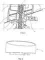
FIG. 3 is a cross-section of a frame-plate according to an aspect of the present disclosure; -
FIG. 4 is a side perspective view of a frame-plate according to an aspect of the present disclosure; and -
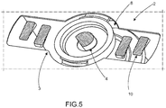
FIG. 5 is a cross-section of a cooking device, which holds the frame-plate and the knob according to an aspect of the present disclosure. - As referenced in
FIGS. 1-5 , the same reference numerals may be used herein to refer to the same parameters and components or their similar modifications and alternatives. For purposes of description herein, the terms "upper," "lower," "right," "left," "rear," "front," "vertical," "horizontal," and derivatives thereof shall relate to the present disclosure as oriented inFIG. 1 . However, it is to be understood that the present disclosure may assume various alternative orientations and step sequences, except where expressly specified to the contrary. It is also to be understood that the specific devices and processes illustrated in the attached drawings, and described in the following specification, are simply exemplary aspects of the concepts defined in the appended claims. Hence, specific dimensions and other physical characteristics relating to the aspects disclosed herein are not to be considered as limiting, unless the claims expressly state otherwise. The drawings referenced herein are schematic and associated views thereof are not necessarily drawn to scale. - Aspects of the present disclosure relate to assembling the frame-plates in an aligned manner between the knobs and the hot panels or cooktops on cooking devices. Aspects of the present disclosure relate to providing a cooking device whose components allow aligned assembly of the frame-plates between the knobs and the hot panels or cooktops, particularly on a large scale.
- As illustrated in
FIGS. 1-5 , the present disclosure refers to a cooking device equipped with a specific construct that allows aligned assembly of the frame-plates between the knobs and the hot panels or cooktops on cooking devices, particularly on a large scale. - To do so, the cooking device of the present disclosure comprises a structure 1 provided with a
surface 2 that comprises at least one opening 3 (shown inFIG. 5 ), corresponding to the ideal positioning for eachknob 5. - The structure 1 provided with a
surface 2 may be either a hot panel or the actual cooktop of the cooking device. - The cooking device includes at least one gas flow control valve, which allows the user to control flames in burners of the cooking device.
- Each gas flow control valve comprises a
rod 4 that extends through the opening 3 of thesurface 2. Therod 4 works in cooperation with theknob 5 arrayed on thesurface 2, whereby it allows interaction between a user and a desired burner flame control. - The cooking device also includes a frame-
plate 6, also referred to as a bezel, arrayed between theknob 5 and thesurface 2, whereby it completely covers the openings 3 in thesurface 2 and provides an aesthetic benefit for the cooking device. - The frame-
plate 6 includes acentral orifice 7 that allows the passage of therod 4 of the gas flow control valve, being particularly rotatable around therod 4 and slotting through interference onto the structure 1 provided with thesurface 2. Thecentral orifice 7 can fit tightly around therod 4, whereby there is little space for misalignment. - The cooking device includes a
separation gap 8 between the frame-plate 6 and the structure 1 provided with thesurface 2, that can offset any misalignment between therod 4 and the opening 3 on thesurface 2. - Slotting into place through an interference fit is materialized particularly through interaction between
protuberances 9 on the actual structure of the frame-plate 6, and a first contact region 11 of the structure 1 provided with thesurface 2. - The frame-
plate 6 also includes at least onegeometry 10, that can have an S-shape, that interacts with asecond contact region 12 of the structure 1 provided with thesurface 2. This interaction ensures a tight snap-fit connection, as indicated by an audible "click" that prevents the displacement or even the removal of the frame-plate 6 by the user after assembly. - The assembly described above and illustrated in the Figures allows the frame-
plate 6 to be easily assembled, slotted, and rotated into its ideal position on thesurface 2 of the cooking device. As a result, the correct alignment of the frame-plate 6 is obtained quickly, avoiding the use of additional means of attachment, such as screws or other fasteners as known in the art. There is also no need for an assembly mold during the fabrication of the device, as required by prior constructions known in the art. - Moreover, slotting into place through an interference fit between the frame-
plate 6 and the structure 1 provided with thesurface 2 prevents easy removal by the end-user, thus avoiding future misalignments. - The following clauses define additional, unclaimed aspects that are encompassed by the present disclosure:
- In one aspect, a method of mounting a frame-plate to a surface of a cooking device is provided, the method including: providing said cooking device having at least one burner and a gas flow valve, said gas flow valve including a rod extending through an opening in said surface, providing said frame-plate having a central orifice and at least one protuberance, passing the rod through the central orifice of the frame-plate, slotting the at least one protuberance through the opening in said surface, and rotating the frame-plate about the rod to engage the at least one protuberance with a first contact region of said surface, wherein rotation of said frame-plate about the rod assembles said frame-plate relative to said surface through an interference fit.
- Additional aspects of the method of mounting a frame-plate to a surface of a cooking which can be used alone or in combination with one or more of the other aspects include: rotating said frame-plate about the rod and engaging a second contact region of said surface through a snap-fit connection; providing said frame-plate with at least one geometry configured to engage the second contact region of said surface through a snap-fit connection; rotating said frame-plate about the rod until an audible "click" is produced; providing said structure including said surface, wherein said structure is one of a hot panel or a cooktop; and/or placing a knob on the rod with said frame-plate arrayed between the knob and said surface and configuring the knob to cooperate with the rod to control the at least one burner.
- In another aspect, a frame-plate is provided for mounting a knob to a surface of a cooking device, the cooking device including at least one burner and a gas flow valve, the gas flow valve including a rod that cooperates with the knob to control the at least one burner, the frame plate comprising: a central orifice configured to allow passage of the rod through the frame-plate, wherein the frame plate is rotatable about the rod, at least one protuberance configured to be slotted through a corresponding opening provided in said surface and to engage a first contact region of said surface through an interference fit when said frame-plate is rotated about the rod, and at least one geometry configured to engage a second contact region of said surface through a snap-fit connection when said frame-plate is rotated about the rod.
- Additional aspects of the frame-plate which can be used alone or in combination with one or more of the other aspects include: the at least one geometry can be configured to provide an audible "click" to indicate when the at least one geometry engages the second contact region of said surface; said frame-plate includes a pair of protuberances and a pair of geometries; the at least one geometry prevents at least one of a removal and displacement of said frame-plate by a user when the at least one geometry engages the second contact region of said surface; and/or the at least one geometry includes an S-shape.
- It is important to stress that the above description is intended only to provide exemplary aspects of the present disclosure. It will be understood that construction-related modifications, variations, and combinations of elements that perform the same function, substantially in the same manner, in order to attain the same results, remain within the protection demarcated by the appended Claims.
- It will be understood by one having ordinary skill in the art that construction of the described present disclosure and other components is not limited to any specific material. Other exemplary aspects of the disclosure disclosed herein may be formed from a wide variety of materials, unless described otherwise herein.
- For purposes of this disclosure, the term "operably coupled" (in all of its forms, couple, coupling, coupled, etc.) generally means the joining of two components (electrical or mechanical) directly or indirectly to one another. Such joining may be stationary in nature or movable in nature. Such joining may be achieved with the two components (electrical or mechanical) and any additional intermediate members being integrally formed as a single unitary body with one another or with the two components. Such joining may be permanent in nature or may be removable or releasable in nature unless otherwise stated.
- For purposes of this disclosure, the term "operably connected" (in all of its forms, connect, connecting, connected, etc.) generally means that one component functions with respect to another component, even if there are other components located between the first and second component, and the term "operable" defines a functional relationship between components.
- It is also important to note that the construction and arrangement of the elements of the present disclosure as shown in the exemplary aspects is illustrative only. Although only a few aspects of the present disclosure have been described in detail in this disclosure, those skilled in the art who review this disclosure will readily appreciate that many modifications are possible, e.g., variations in sizes, dimensions, structures, shapes and proportions of the various elements, values of parameters, mounting arrangements, use of materials, colors, orientations, etc. without materially departing from the novel teachings and advantages of the subject matter recited. For example, elements shown as integrally formed may be constructed of multiple parts or elements shown in multiple parts may be integrally formed, the operation of the interfaces may be reversed or otherwise varied, the length or width of the structures and/or members or connector or other elements of the system may be varied, the nature or number of adjustment positions provided between the elements may be varied. It should be noted that the elements and/or assemblies of the system may be constructed from any of the wide variety of materials that provide sufficient strength or durability, in any of the wide variety of colors, textures, and combinations. Accordingly, all such modifications are intended to be included within the scope of the present innovations. Other substitutions, modifications, changes, and omissions may be made in the design, operating conditions, and arrangement of the desired and other exemplary embodiments without departing from the spirit of the present innovations.
- It will be understood that any described processes or steps within described processes may be combined with other disclosed processes or steps to form structures within the scope of the present disclosure. The exemplary structures and processes disclosed herein are for illustrative purposes and are not to be construed as limiting.
- It is to be understood that variations and modifications can be made on the aforementioned structure and method without departing from the concepts of the present disclosure, and further it is to be understood that such concepts are intended to be covered by the following claims unless these claims by their language expressly state otherwise.
Claims (15)
- A cooking device comprising at least one burner, the cooking device comprising:a structure (1) including a surface (2) having an opening (3);a gas flow valve configured to control a flow of gas to the at least one burner, the gas flow valve including a rod (4) extending through the opening (3) in the surface (2);a knob (5) arrayed on the surface (2) and configured to cooperate with the rod (4) to control the flow of gas to the at least one burner; anda frame-plate (6) disposed between the knob (5) and the surface (2), wherein the frame-plate (6) comprises a central orifice (7) configured to allow passage of the rod (4) through the frame-plate (6), and wherein the frame-plate (6) is configured to be slotted through the opening (3) and is rotatable about the rod (4) to align the frame-plate (6) relative to the surface (2).
- The cooking device according to claim 1, further comprising:a gap (8) defined between the frame-plate (6) and the surface (2).
- The cooking device according to claims 1 or 2, wherein the frame-plate (6) comprises at least one protuberance (9) configured to engage a first contact region (11) of the surface (2) through an interference fit.
- The cooking device according to any of claims 1-3, wherein the at least one protuberance (9) is configured to pass through the opening (3) in the surface (2) and engage the first contact region (11) of the surface (2) upon rotation of the frame-plate (6) about the rod (4) to align the frame-plate (6) relative to the surface (2).
- The cooking device according to claim 4, wherein the frame-plate (6) comprises at least one geometry (10) configured to engage a second contact region (12) of the surface (2) through a snap-fit connection upon rotation of the frame-plate (6) about the rod (4).
- The cooking device according to claim 5, wherein the at least one geometry (10) prevents at least one of removal and displacement of the frame-plate (6) by a user when the at least one geometry (10) engages the second contact region (12) of the surface (2).
- The cooking device according to claims 5 or 6, wherein the at least one geometry (10) comprises an S-shape.
- The cooking device according to any of claims 5-7, wherein the at least one geometry (10) is configured to provide an audible "click" to indicate when the at least one geometry (10) engages the second contact region (12) of the surface (2).
- The cooking device according to any of claims 5-8, wherein the frame-plate (6) comprises a pair of protuberances (9) and a pair of geometries (10).
- The cooking device according to any of claims 1-9, wherein the structure (1) including the surface (2) is one of a hot panel or a cooktop.
- The cooking device according to any of claims 1-10, wherein the frame-plate (6) is configured to cover the opening (3) in the surface (2).
- A method of making the cooking device of claim 1, the method comprising:passing the rod (4) through the central orifice (7) of said frame-plate (6);slotting the at least one protuberance (9) through the opening (3) in said surface (2); androtating said frame-plate (6) about the rod (4) to engage the at least one protuberance (9) with a first contact region (11) of said surface (2), wherein rotation of said frame-plate (6) about the rod (4) assembles said frame-plate (6) relative to said surface (2) through an interference fit.
- The method according to claim 12, further comprising:rotating said frame-plate (6) about the rod (4); andengaging a second contact region (12) of said surface (2) through a snap-fit connection.
- The method according to claim 13, further comprising providing said frame-plate (6) with at least one geometry (10) configured to engage the second contact region (12) of said surface (2) through a snap-fit connection.
- The method according to claim 13 or 14, further comprising:rotating said frame-plate (6) about the rod (4) until an audible "click" is produced.
Applications Claiming Priority (1)
| Application Number | Priority Date | Filing Date | Title |
|---|---|---|---|
| BR102017026633-8A BR102017026633B1 (en) | 2017-12-11 | 2017-12-11 | COOKING APPLIANCE |
Publications (2)
| Publication Number | Publication Date |
|---|---|
| EP3495739A1 true EP3495739A1 (en) | 2019-06-12 |
| EP3495739B1 EP3495739B1 (en) | 2020-09-09 |
Family
ID=64664945
Family Applications (1)
| Application Number | Title | Priority Date | Filing Date |
|---|---|---|---|
| EP18211796.0A Active EP3495739B1 (en) | 2017-12-11 | 2018-12-11 | Cooking device comprising a bezel coupling system with better alignment of knobs and method of assembling such a device |
Country Status (3)
| Country | Link |
|---|---|
| US (1) | US11098903B2 (en) |
| EP (1) | EP3495739B1 (en) |
| BR (1) | BR102017026633B1 (en) |
Families Citing this family (3)
| Publication number | Priority date | Publication date | Assignee | Title |
|---|---|---|---|---|
| US12535221B2 (en) | 2021-10-28 | 2026-01-27 | Haier Us Appliance Solutions, Inc. | Cooktop appliance with unifying alignment bracket |
| US12148583B2 (en) | 2022-08-01 | 2024-11-19 | Whirlpool Corporation | Removable bezel assembly for a cooking appliance |
| US12504777B1 (en) | 2024-09-20 | 2025-12-23 | Whirlpool Corporation | Systems for interchangeable knob assemblies |
Citations (7)
| Publication number | Priority date | Publication date | Assignee | Title |
|---|---|---|---|---|
| DE10249671A1 (en) * | 2001-10-25 | 2003-05-15 | Bsh Bosch Siemens Hausgeraete | Switch structure for household appliance inserts switch in panel with pot-shaped casing to retain switching element and panel supporting wall with opening to retain casing plugged into opening and locked |
| US20060254573A1 (en) * | 2005-05-10 | 2006-11-16 | Mark Steinman | Control knob assembly |
| WO2009083393A1 (en) * | 2007-12-31 | 2009-07-09 | Arcelik Anonim Sirketi | A household appliance |
| EP2436828A1 (en) * | 2010-09-30 | 2012-04-04 | Electrolux Home Products Corporation N.V. | A control panel assembly for a domestic appliance |
| US20160265786A1 (en) * | 2015-03-11 | 2016-09-15 | Lg Electronics Inc. | Cooking appliance |
| CN106580119A (en) * | 2016-12-12 | 2017-04-26 | 广东美的厨房电器制造有限公司 | Oven and control board component for same |
| US20170191671A1 (en) | 2016-01-04 | 2017-07-06 | General Electric Company | Cooktop Appliance |
Family Cites Families (5)
| Publication number | Priority date | Publication date | Assignee | Title |
|---|---|---|---|---|
| US20030221498A1 (en) | 2002-05-30 | 2003-12-04 | Shadi Mere | Control knob to position encoder interface with self-aligning rotary guide |
| US8733204B2 (en) | 2007-02-23 | 2014-05-27 | Weber-Stephen Products Co. | Sliding bezel |
| US9127846B2 (en) | 2011-06-03 | 2015-09-08 | General Electric Company | Coupling assembly for use with a valve assembly |
| KR101623795B1 (en) * | 2014-10-07 | 2016-06-07 | 엘지전자 주식회사 | cooking appliance |
| US9852856B2 (en) | 2015-05-05 | 2017-12-26 | Archie Brooks Bowen | High temperature control knob |
-
2017
- 2017-12-11 BR BR102017026633-8A patent/BR102017026633B1/en active IP Right Grant
-
2018
- 2018-12-07 US US16/213,519 patent/US11098903B2/en not_active Expired - Fee Related
- 2018-12-11 EP EP18211796.0A patent/EP3495739B1/en active Active
Patent Citations (7)
| Publication number | Priority date | Publication date | Assignee | Title |
|---|---|---|---|---|
| DE10249671A1 (en) * | 2001-10-25 | 2003-05-15 | Bsh Bosch Siemens Hausgeraete | Switch structure for household appliance inserts switch in panel with pot-shaped casing to retain switching element and panel supporting wall with opening to retain casing plugged into opening and locked |
| US20060254573A1 (en) * | 2005-05-10 | 2006-11-16 | Mark Steinman | Control knob assembly |
| WO2009083393A1 (en) * | 2007-12-31 | 2009-07-09 | Arcelik Anonim Sirketi | A household appliance |
| EP2436828A1 (en) * | 2010-09-30 | 2012-04-04 | Electrolux Home Products Corporation N.V. | A control panel assembly for a domestic appliance |
| US20160265786A1 (en) * | 2015-03-11 | 2016-09-15 | Lg Electronics Inc. | Cooking appliance |
| US20170191671A1 (en) | 2016-01-04 | 2017-07-06 | General Electric Company | Cooktop Appliance |
| CN106580119A (en) * | 2016-12-12 | 2017-04-26 | 广东美的厨房电器制造有限公司 | Oven and control board component for same |
Also Published As
| Publication number | Publication date |
|---|---|
| BR102017026633A2 (en) | 2019-06-25 |
| BR102017026633B1 (en) | 2022-08-30 |
| EP3495739B1 (en) | 2020-09-09 |
| US20190178499A1 (en) | 2019-06-13 |
| US11098903B2 (en) | 2021-08-24 |
Similar Documents
| Publication | Publication Date | Title |
|---|---|---|
| US11098903B2 (en) | Bezel coupling system with better alignment to knobs applied for cooking products | |
| KR102719412B1 (en) | Knob assembly having display and home appliance using the same | |
| KR102327680B1 (en) | Knob assembly for cook top | |
| KR102346353B1 (en) | Knob assembly for cook top | |
| DE102016101008B4 (en) | cooking utensil | |
| US11243556B2 (en) | Knob assembly for a cooking appliance and method of assembling | |
| DE19504471B4 (en) | Control panel for home appliances | |
| US9476594B2 (en) | Domestic cooking appliance having a gas switch mounting system | |
| RU2559996C2 (en) | Household cooking stove | |
| US12535221B2 (en) | Cooktop appliance with unifying alignment bracket | |
| US20150153046A1 (en) | Gas-heated cooking device | |
| CN108836132A (en) | Sealing strip and sealing structure and cooking apparatus with it | |
| US20180023815A1 (en) | Sliding orifice holder for a gas powered cooktop | |
| CN109764359B (en) | Combustion chamber head assembly structure, combustion chamber and aeroengine | |
| US12104801B2 (en) | Gas cooking appliance | |
| US12504777B1 (en) | Systems for interchangeable knob assemblies | |
| US10422536B2 (en) | Domestic oven | |
| EP0453807A1 (en) | Adjustable device, especially electrical switch-, control- or regulating device | |
| EP2798271B1 (en) | A cooking device | |
| US20260139843A1 (en) | Console backer for front console system | |
| KR101460203B1 (en) | knob of gas range | |
| US12148583B2 (en) | Removable bezel assembly for a cooking appliance | |
| CA3100893C (en) | Control panel mechanism of a range hood | |
| EP2238389B1 (en) | A household appliance | |
| KR100966715B1 (en) | Air conditioner for gas range |
Legal Events
| Date | Code | Title | Description |
|---|---|---|---|
| PUAI | Public reference made under article 153(3) epc to a published international application that has entered the european phase |
Free format text: ORIGINAL CODE: 0009012 |
|
| STAA | Information on the status of an ep patent application or granted ep patent |
Free format text: STATUS: THE APPLICATION HAS BEEN PUBLISHED |
|
| AK | Designated contracting states |
Kind code of ref document: A1 Designated state(s): AL AT BE BG CH CY CZ DE DK EE ES FI FR GB GR HR HU IE IS IT LI LT LU LV MC MK MT NL NO PL PT RO RS SE SI SK SM TR |
|
| AX | Request for extension of the european patent |
Extension state: BA ME |
|
| STAA | Information on the status of an ep patent application or granted ep patent |
Free format text: STATUS: REQUEST FOR EXAMINATION WAS MADE |
|
| 17P | Request for examination filed |
Effective date: 20191204 |
|
| RBV | Designated contracting states (corrected) |
Designated state(s): AL AT BE BG CH CY CZ DE DK EE ES FI FR GB GR HR HU IE IS IT LI LT LU LV MC MK MT NL NO PL PT RO RS SE SI SK SM TR |
|
| GRAP | Despatch of communication of intention to grant a patent |
Free format text: ORIGINAL CODE: EPIDOSNIGR1 |
|
| STAA | Information on the status of an ep patent application or granted ep patent |
Free format text: STATUS: GRANT OF PATENT IS INTENDED |
|
| INTG | Intention to grant announced |
Effective date: 20200703 |
|
| GRAS | Grant fee paid |
Free format text: ORIGINAL CODE: EPIDOSNIGR3 |
|
| GRAA | (expected) grant |
Free format text: ORIGINAL CODE: 0009210 |
|
| STAA | Information on the status of an ep patent application or granted ep patent |
Free format text: STATUS: THE PATENT HAS BEEN GRANTED |
|
| AK | Designated contracting states |
Kind code of ref document: B1 Designated state(s): AL AT BE BG CH CY CZ DE DK EE ES FI FR GB GR HR HU IE IS IT LI LT LU LV MC MK MT NL NO PL PT RO RS SE SI SK SM TR |
|
| REG | Reference to a national code |
Ref country code: GB Ref legal event code: FG4D |
|
| REG | Reference to a national code |
Ref country code: AT Ref legal event code: REF Ref document number: 1312034 Country of ref document: AT Kind code of ref document: T Effective date: 20200915 Ref country code: CH Ref legal event code: EP |
|
| REG | Reference to a national code |
Ref country code: DE Ref legal event code: R096 Ref document number: 602018007651 Country of ref document: DE |
|
| REG | Reference to a national code |
Ref country code: IE Ref legal event code: FG4D |
|
| REG | Reference to a national code |
Ref country code: LT Ref legal event code: MG4D |
|
| PG25 | Lapsed in a contracting state [announced via postgrant information from national office to epo] |
Ref country code: FI Free format text: LAPSE BECAUSE OF FAILURE TO SUBMIT A TRANSLATION OF THE DESCRIPTION OR TO PAY THE FEE WITHIN THE PRESCRIBED TIME-LIMIT Effective date: 20200909 Ref country code: SE Free format text: LAPSE BECAUSE OF FAILURE TO SUBMIT A TRANSLATION OF THE DESCRIPTION OR TO PAY THE FEE WITHIN THE PRESCRIBED TIME-LIMIT Effective date: 20200909 Ref country code: NO Free format text: LAPSE BECAUSE OF FAILURE TO SUBMIT A TRANSLATION OF THE DESCRIPTION OR TO PAY THE FEE WITHIN THE PRESCRIBED TIME-LIMIT Effective date: 20201209 Ref country code: BG Free format text: LAPSE BECAUSE OF FAILURE TO SUBMIT A TRANSLATION OF THE DESCRIPTION OR TO PAY THE FEE WITHIN THE PRESCRIBED TIME-LIMIT Effective date: 20201209 Ref country code: HR Free format text: LAPSE BECAUSE OF FAILURE TO SUBMIT A TRANSLATION OF THE DESCRIPTION OR TO PAY THE FEE WITHIN THE PRESCRIBED TIME-LIMIT Effective date: 20200909 Ref country code: LT Free format text: LAPSE BECAUSE OF FAILURE TO SUBMIT A TRANSLATION OF THE DESCRIPTION OR TO PAY THE FEE WITHIN THE PRESCRIBED TIME-LIMIT Effective date: 20200909 |
|
| REG | Reference to a national code |
Ref country code: AT Ref legal event code: MK05 Ref document number: 1312034 Country of ref document: AT Kind code of ref document: T Effective date: 20200909 |
|
| REG | Reference to a national code |
Ref country code: NL Ref legal event code: MP Effective date: 20200909 |
|
| PG25 | Lapsed in a contracting state [announced via postgrant information from national office to epo] |
Ref country code: LV Free format text: LAPSE BECAUSE OF FAILURE TO SUBMIT A TRANSLATION OF THE DESCRIPTION OR TO PAY THE FEE WITHIN THE PRESCRIBED TIME-LIMIT Effective date: 20200909 Ref country code: PL Free format text: LAPSE BECAUSE OF FAILURE TO SUBMIT A TRANSLATION OF THE DESCRIPTION OR TO PAY THE FEE WITHIN THE PRESCRIBED TIME-LIMIT Effective date: 20200909 Ref country code: RS Free format text: LAPSE BECAUSE OF FAILURE TO SUBMIT A TRANSLATION OF THE DESCRIPTION OR TO PAY THE FEE WITHIN THE PRESCRIBED TIME-LIMIT Effective date: 20200909 |
|
| PG25 | Lapsed in a contracting state [announced via postgrant information from national office to epo] |
Ref country code: SM Free format text: LAPSE BECAUSE OF FAILURE TO SUBMIT A TRANSLATION OF THE DESCRIPTION OR TO PAY THE FEE WITHIN THE PRESCRIBED TIME-LIMIT Effective date: 20200909 Ref country code: EE Free format text: LAPSE BECAUSE OF FAILURE TO SUBMIT A TRANSLATION OF THE DESCRIPTION OR TO PAY THE FEE WITHIN THE PRESCRIBED TIME-LIMIT Effective date: 20200909 Ref country code: RO Free format text: LAPSE BECAUSE OF FAILURE TO SUBMIT A TRANSLATION OF THE DESCRIPTION OR TO PAY THE FEE WITHIN THE PRESCRIBED TIME-LIMIT Effective date: 20200909 Ref country code: PT Free format text: LAPSE BECAUSE OF FAILURE TO SUBMIT A TRANSLATION OF THE DESCRIPTION OR TO PAY THE FEE WITHIN THE PRESCRIBED TIME-LIMIT Effective date: 20210111 Ref country code: CZ Free format text: LAPSE BECAUSE OF FAILURE TO SUBMIT A TRANSLATION OF THE DESCRIPTION OR TO PAY THE FEE WITHIN THE PRESCRIBED TIME-LIMIT Effective date: 20200909 |
|
| PG25 | Lapsed in a contracting state [announced via postgrant information from national office to epo] |
Ref country code: IS Free format text: LAPSE BECAUSE OF FAILURE TO SUBMIT A TRANSLATION OF THE DESCRIPTION OR TO PAY THE FEE WITHIN THE PRESCRIBED TIME-LIMIT Effective date: 20210109 Ref country code: ES Free format text: LAPSE BECAUSE OF FAILURE TO SUBMIT A TRANSLATION OF THE DESCRIPTION OR TO PAY THE FEE WITHIN THE PRESCRIBED TIME-LIMIT Effective date: 20200909 Ref country code: AL Free format text: LAPSE BECAUSE OF FAILURE TO SUBMIT A TRANSLATION OF THE DESCRIPTION OR TO PAY THE FEE WITHIN THE PRESCRIBED TIME-LIMIT Effective date: 20200909 Ref country code: AT Free format text: LAPSE BECAUSE OF FAILURE TO SUBMIT A TRANSLATION OF THE DESCRIPTION OR TO PAY THE FEE WITHIN THE PRESCRIBED TIME-LIMIT Effective date: 20200909 |
|
| REG | Reference to a national code |
Ref country code: DE Ref legal event code: R097 Ref document number: 602018007651 Country of ref document: DE |
|
| PG25 | Lapsed in a contracting state [announced via postgrant information from national office to epo] |
Ref country code: SK Free format text: LAPSE BECAUSE OF FAILURE TO SUBMIT A TRANSLATION OF THE DESCRIPTION OR TO PAY THE FEE WITHIN THE PRESCRIBED TIME-LIMIT Effective date: 20200909 |
|
| PLBE | No opposition filed within time limit |
Free format text: ORIGINAL CODE: 0009261 |
|
| STAA | Information on the status of an ep patent application or granted ep patent |
Free format text: STATUS: NO OPPOSITION FILED WITHIN TIME LIMIT |
|
| 26N | No opposition filed |
Effective date: 20210610 |
|
| PG25 | Lapsed in a contracting state [announced via postgrant information from national office to epo] |
Ref country code: MC Free format text: LAPSE BECAUSE OF FAILURE TO SUBMIT A TRANSLATION OF THE DESCRIPTION OR TO PAY THE FEE WITHIN THE PRESCRIBED TIME-LIMIT Effective date: 20200909 Ref country code: DK Free format text: LAPSE BECAUSE OF FAILURE TO SUBMIT A TRANSLATION OF THE DESCRIPTION OR TO PAY THE FEE WITHIN THE PRESCRIBED TIME-LIMIT Effective date: 20200909 Ref country code: SI Free format text: LAPSE BECAUSE OF FAILURE TO SUBMIT A TRANSLATION OF THE DESCRIPTION OR TO PAY THE FEE WITHIN THE PRESCRIBED TIME-LIMIT Effective date: 20200909 |
|
| REG | Reference to a national code |
Ref country code: BE Ref legal event code: MM Effective date: 20201231 |
|
| PG25 | Lapsed in a contracting state [announced via postgrant information from national office to epo] |
Ref country code: LU Free format text: LAPSE BECAUSE OF NON-PAYMENT OF DUE FEES Effective date: 20201211 Ref country code: IE Free format text: LAPSE BECAUSE OF NON-PAYMENT OF DUE FEES Effective date: 20201211 |
|
| PG25 | Lapsed in a contracting state [announced via postgrant information from national office to epo] |
Ref country code: TR Free format text: LAPSE BECAUSE OF FAILURE TO SUBMIT A TRANSLATION OF THE DESCRIPTION OR TO PAY THE FEE WITHIN THE PRESCRIBED TIME-LIMIT Effective date: 20200909 Ref country code: MT Free format text: LAPSE BECAUSE OF FAILURE TO SUBMIT A TRANSLATION OF THE DESCRIPTION OR TO PAY THE FEE WITHIN THE PRESCRIBED TIME-LIMIT Effective date: 20200909 Ref country code: CY Free format text: LAPSE BECAUSE OF FAILURE TO SUBMIT A TRANSLATION OF THE DESCRIPTION OR TO PAY THE FEE WITHIN THE PRESCRIBED TIME-LIMIT Effective date: 20200909 |
|
| PG25 | Lapsed in a contracting state [announced via postgrant information from national office to epo] |
Ref country code: MK Free format text: LAPSE BECAUSE OF FAILURE TO SUBMIT A TRANSLATION OF THE DESCRIPTION OR TO PAY THE FEE WITHIN THE PRESCRIBED TIME-LIMIT Effective date: 20200909 |
|
| PG25 | Lapsed in a contracting state [announced via postgrant information from national office to epo] |
Ref country code: GR Free format text: LAPSE BECAUSE OF FAILURE TO SUBMIT A TRANSLATION OF THE DESCRIPTION OR TO PAY THE FEE WITHIN THE PRESCRIBED TIME-LIMIT Effective date: 20200909 Ref country code: BE Free format text: LAPSE BECAUSE OF NON-PAYMENT OF DUE FEES Effective date: 20201231 |
|
| REG | Reference to a national code |
Ref country code: CH Ref legal event code: PL |
|
| PG25 | Lapsed in a contracting state [announced via postgrant information from national office to epo] |
Ref country code: LI Free format text: LAPSE BECAUSE OF NON-PAYMENT OF DUE FEES Effective date: 20211231 Ref country code: CH Free format text: LAPSE BECAUSE OF NON-PAYMENT OF DUE FEES Effective date: 20211231 |
|
| P01 | Opt-out of the competence of the unified patent court (upc) registered |
Effective date: 20230523 |
|
| PG25 | Lapsed in a contracting state [announced via postgrant information from national office to epo] |
Ref country code: NL Free format text: LAPSE BECAUSE OF NON-PAYMENT OF DUE FEES Effective date: 20200923 |
|
| PGFP | Annual fee paid to national office [announced via postgrant information from national office to epo] |
Ref country code: GB Payment date: 20241217 Year of fee payment: 7 |
|
| PGFP | Annual fee paid to national office [announced via postgrant information from national office to epo] |
Ref country code: FR Payment date: 20241227 Year of fee payment: 7 |
|
| PGFP | Annual fee paid to national office [announced via postgrant information from national office to epo] |
Ref country code: IT Payment date: 20241121 Year of fee payment: 7 |
|
| PGFP | Annual fee paid to national office [announced via postgrant information from national office to epo] |
Ref country code: DE Payment date: 20241227 Year of fee payment: 7 |