EP3495706A1 - Raccord de conduite à capteur intégré permettant de mesurer des solutions d'urée - Google Patents
Raccord de conduite à capteur intégré permettant de mesurer des solutions d'urée Download PDFInfo
- Publication number
- EP3495706A1 EP3495706A1 EP18208326.1A EP18208326A EP3495706A1 EP 3495706 A1 EP3495706 A1 EP 3495706A1 EP 18208326 A EP18208326 A EP 18208326A EP 3495706 A1 EP3495706 A1 EP 3495706A1
- Authority
- EP
- European Patent Office
- Prior art keywords
- connector according
- cable connector
- connection
- flow channel
- receiving
- Prior art date
- Legal status (The legal status is an assumption and is not a legal conclusion. Google has not performed a legal analysis and makes no representation as to the accuracy of the status listed.)
- Granted
Links
- XSQUKJJJFZCRTK-UHFFFAOYSA-N Urea Chemical compound NC(N)=O XSQUKJJJFZCRTK-UHFFFAOYSA-N 0.000 title claims abstract description 46
- 239000004202 carbamide Substances 0.000 title claims abstract description 46
- 230000003287 optical effect Effects 0.000 claims abstract description 34
- 239000012530 fluid Substances 0.000 claims abstract description 5
- 239000000243 solution Substances 0.000 claims description 47
- 239000004020 conductor Substances 0.000 claims description 28
- 238000010438 heat treatment Methods 0.000 claims description 15
- 239000000463 material Substances 0.000 claims description 13
- 238000005538 encapsulation Methods 0.000 claims description 10
- 230000002093 peripheral effect Effects 0.000 claims description 10
- 230000007704 transition Effects 0.000 claims description 6
- 238000003466 welding Methods 0.000 claims description 6
- 239000004033 plastic Substances 0.000 claims description 5
- 238000002347 injection Methods 0.000 claims description 4
- 239000007924 injection Substances 0.000 claims description 4
- 239000003054 catalyst Substances 0.000 claims description 2
- 239000002991 molded plastic Substances 0.000 claims description 2
- 230000037431 insertion Effects 0.000 claims 2
- 238000003780 insertion Methods 0.000 claims 2
- 238000007789 sealing Methods 0.000 claims 1
- 238000005259 measurement Methods 0.000 description 11
- 230000006378 damage Effects 0.000 description 7
- 230000008014 freezing Effects 0.000 description 3
- 238000007710 freezing Methods 0.000 description 3
- 239000007789 gas Substances 0.000 description 3
- 239000007788 liquid Substances 0.000 description 3
- MWUXSHHQAYIFBG-UHFFFAOYSA-N nitrogen oxide Inorganic materials O=[N] MWUXSHHQAYIFBG-UHFFFAOYSA-N 0.000 description 3
- 230000005855 radiation Effects 0.000 description 3
- IJGRMHOSHXDMSA-UHFFFAOYSA-N Atomic nitrogen Chemical compound N#N IJGRMHOSHXDMSA-UHFFFAOYSA-N 0.000 description 2
- 230000002411 adverse Effects 0.000 description 2
- 239000000356 contaminant Substances 0.000 description 2
- 238000005516 engineering process Methods 0.000 description 2
- 238000009434 installation Methods 0.000 description 2
- 230000035515 penetration Effects 0.000 description 2
- 230000035508 accumulation Effects 0.000 description 1
- 238000009825 accumulation Methods 0.000 description 1
- QVGXLLKOCUKJST-UHFFFAOYSA-N atomic oxygen Chemical compound [O] QVGXLLKOCUKJST-UHFFFAOYSA-N 0.000 description 1
- 238000011109 contamination Methods 0.000 description 1
- 238000000265 homogenisation Methods 0.000 description 1
- 238000004519 manufacturing process Methods 0.000 description 1
- 238000000034 method Methods 0.000 description 1
- 238000002156 mixing Methods 0.000 description 1
- 229910052757 nitrogen Inorganic materials 0.000 description 1
- 239000001301 oxygen Substances 0.000 description 1
- 229910052760 oxygen Inorganic materials 0.000 description 1
- 239000002245 particle Substances 0.000 description 1
- 230000001681 protective effect Effects 0.000 description 1
- 238000003908 quality control method Methods 0.000 description 1
- 238000005476 soldering Methods 0.000 description 1
- 230000008674 spewing Effects 0.000 description 1
- 231100000331 toxic Toxicity 0.000 description 1
- 230000002588 toxic effect Effects 0.000 description 1
- 238000002834 transmittance Methods 0.000 description 1
Images


Classifications
-
- F—MECHANICAL ENGINEERING; LIGHTING; HEATING; WEAPONS; BLASTING
- F16—ENGINEERING ELEMENTS AND UNITS; GENERAL MEASURES FOR PRODUCING AND MAINTAINING EFFECTIVE FUNCTIONING OF MACHINES OR INSTALLATIONS; THERMAL INSULATION IN GENERAL
- F16L—PIPES; JOINTS OR FITTINGS FOR PIPES; SUPPORTS FOR PIPES, CABLES OR PROTECTIVE TUBING; MEANS FOR THERMAL INSULATION IN GENERAL
- F16L53/00—Heating of pipes or pipe systems; Cooling of pipes or pipe systems
- F16L53/30—Heating of pipes or pipe systems
- F16L53/35—Ohmic-resistance heating
- F16L53/38—Ohmic-resistance heating using elongate electric heating elements, e.g. wires or ribbons
-
- F—MECHANICAL ENGINEERING; LIGHTING; HEATING; WEAPONS; BLASTING
- F16—ENGINEERING ELEMENTS AND UNITS; GENERAL MEASURES FOR PRODUCING AND MAINTAINING EFFECTIVE FUNCTIONING OF MACHINES OR INSTALLATIONS; THERMAL INSULATION IN GENERAL
- F16L—PIPES; JOINTS OR FITTINGS FOR PIPES; SUPPORTS FOR PIPES, CABLES OR PROTECTIVE TUBING; MEANS FOR THERMAL INSULATION IN GENERAL
- F16L25/00—Constructive types of pipe joints not provided for in groups F16L13/00 - F16L23/00 ; Details of pipe joints not otherwise provided for, e.g. electrically conducting or insulating means
- F16L25/01—Constructive types of pipe joints not provided for in groups F16L13/00 - F16L23/00 ; Details of pipe joints not otherwise provided for, e.g. electrically conducting or insulating means specially adapted for realising electrical conduction between the two pipe ends of the joint or between parts thereof
-
- F—MECHANICAL ENGINEERING; LIGHTING; HEATING; WEAPONS; BLASTING
- F16—ENGINEERING ELEMENTS AND UNITS; GENERAL MEASURES FOR PRODUCING AND MAINTAINING EFFECTIVE FUNCTIONING OF MACHINES OR INSTALLATIONS; THERMAL INSULATION IN GENERAL
- F16L—PIPES; JOINTS OR FITTINGS FOR PIPES; SUPPORTS FOR PIPES, CABLES OR PROTECTIVE TUBING; MEANS FOR THERMAL INSULATION IN GENERAL
- F16L41/00—Branching pipes; Joining pipes to walls
- F16L41/008—Branching pipes; Joining pipes to walls for connecting a measuring instrument
Definitions
- the present invention relates to a pipe connector comprising a connector piece having a urea solution flow channel extending in its interior in the longitudinal direction of the connector piece, the connector piece having at its both ends a connection portion formed such that a flexible media pipe or a pipe or an aggregate with an aggregate connection can be connected, and the flow channel is provided with an electric heater.
- Such a line connector is for example from the EP 2 137 449 B1 known.
- the urea solution is conveyed from a separate tank via piping and connection technology to a metering unit for the injection of the urea solution into the exhaust gas line.
- the quality and the correct mixing ratio of the urea solution must be monitored in order to achieve the respective legal requirements. This is fulfilled by a urea quality sensor.
- the current quality sensor is usually located in a tank for receiving the urea solution. There she is either sunk in the medium or sitting in the medium Tank wall. Recessed sensors are attached to a tank header unit (head unit), which also thaws the urea solution in the tank. Sensors sitting in the tank wall are fixed to the tank by a device. A suitable seal prevents the escape of urea solution from the tank.
- Various solutions are known for electronically measuring the quality of the urea solution.
- one known technique is measuring ultrasonic wave transit times by means of an ultrasonic sensor.
- thermal or optical sensor systems are used.
- the known measuring systems have the disadvantage, in particular in commercial vehicles or in off-road vehicles, that there are many different tank geometries for the tank for receiving the urea solutions, wherein the position of the sensor in or on the tank has to be redetermined for each tank. This results in a large variety of variants.
- the tank contains a significant amount of urea solution, at temperatures below freezing can certainly form larger chunks of ice within the tank solution, which also adversely affect the measurement and also damage the sensor by a back and forth spewing the solution mechanically.
- Measuring sensors located in the tank wall can lead to the loss of a large amount of urea solution in the event of a leak. Furthermore, immersed in the tank measuring sensors are completely surrounded by the urea solution. Thus, all electrical connections must also be introduced into the tank housing. In addition, they must be protected against the penetration of urea solution. In fact, penetration of the urea solution can lead to the destruction of the respective measuring sensor. In addition, the urea solution can also creep into the wiring harness of the connected electrical cable and cause further damage in the vehicle.
- the complete tank for the urea solution must be emptied in case of service to replace the measuring sensor. With measuring sensors in the tank header, this must be completely removed, which is associated with considerable effort and costs.
- the present invention has for its object to provide a mounting possibility of a measuring sensor for measuring properties of the urea solution, which avoids the above disadvantages and is characterized by a compact and inexpensive to produce structure.
- the invention is based on the finding that the measurement of the properties of the urea solution flowing in the flow channel takes place directly in the flow channel itself, so that the measuring sensor is thus part of the line connector itself.
- the installation of the measuring sensor is independent of the respective tank geometry, also the tank geometry can be selected independently of the installation of such a measuring sensor.
- a wall section permeable to an optical sensor signal is formed in a wall of the connector piece surrounding the flow channel, and a receiving housing peripherally surrounding the permeable wall section on the connector piece is formed, which has a the permeable wall portion opposite receiving opening for mounting the optical sensor unit within the receiving housing.
- the optical sensor according to the invention preferably emits light in the IR range through the permeable wall section into the medium.
- the light is reflected at the surface of the urea solution and by the sensor signal permeable surface or passed through the permeable wall section back to the sensor.
- the reflection angle and / or the intensity of the reflected light provide feedback on the quality of the urea solution.
- the permeable wall section is formed as an open breakthrough in the wall.
- the sensor unit has such a cover on its side opposite the aperture that the cover closes the open aperture and itself consists of a material permeable to the optical sensor signal.
- the sensor unit forms part of the wall of the flow channel.
- the flow channel of the connector piece is limited by this cover in the region of its breakthrough.
- the advantageously present according to the invention sensor is part of a closed sensor body, so that the sensor present within the sensor body itself is protected against the existing urea solution.
- the sensor body, which contains the measuring sensor is sealed by means of an O-ring seal with respect to the receiving housing of the line connector.
- This design of the seal is characterized by a simple design and ensures a seal to the outside, so that the existing urea solution can not escape to the outside.
- An expedient embodiment of an attachment of the sensor body to the receiving housing of the line connector can be done for example by material bond, for example by laser welding, which laser welding can not be formed circumferentially and also does not serve to seal the sensor body relative to the receiving housing. It serves only for holding the sensor body in the receiving housing.
- the Sensor body with the receiving housing can also be provided advantageously a mechanical connection between the two parts, for example by means of a bayonet-type connection.
- a clip-like locking of the two parts would be advantageous, with a releasable and a non-releasable clip connection in the form of a latch can be advantageous.
- the flow passage in the sensor housing has an enlarged cross-section with respect to the flow channels in the connection sections, with which a speed reduction of the medium flowing in the channels is connected.
- the line system in which a line connector according to the invention is integrated is subjected to multiple emptying and refilling, it may be possible for air bubbles to be held in the area of the measuring point and, as a result, the measurement result may be influenced as a result.
- it may be expedient according to the invention if a narrowing of the flow channel is provided in the measuring range of the sensor and thus an increase in speed of the flow rate of the medium is connected, which causes the air bubbles possibly held there to be removed. It is advantageous if the cross-sectional constriction, starting from the respective flow channels of the connection sections, takes place continuously, so that there is no sudden transition of the different cross sections.
- the material sections of the line connector according to the invention which surround the measuring point for example existing protective caps or the respective counter-contours, consist of a material which is opaque to UV or IR light, so that these are eliminated Light influences is given, and is given only a light transmittance for the measuring wavelength of the optical sensor.
- Advantageous embodiments of the invention are contained in the subclaims.
- the individual features of the subclaims can be combined individually or in combination with the features of the main claim.
- the line connector according to the invention can be integrated into a heated or unheated media line, so that an intelligent prefabricated line for the forwarding of urea solutions is created, wherein due to the heatability of the line connector and the connected media line an accurate and defined operating performance is realized.
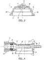
- a connector piece 1 with a running in its longitudinal direction in the connector piece 1 flow channel 2 for a fluid, in particular a urea solution, wherein the connector piece 1 at its two ends in each case a connection portion 3, 4, which is formed in that a flexible media line 6, see Fig. 8 , or a conduit or an aggregate with an aggregate connection can be connected.
- the flow channel 2 is provided with an electric heater 7 or heated, see Fig. 4 ,
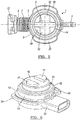
- a wall section 8 which is permeable to an optical sensor signal is formed in a wall of the connector piece 1 surrounding the flow channel 2 Fig. 5 is shown as a breakthrough is made.
- the permeable for an optical sensor signal wall portion 8, in particular the opening, circumferentially surrounds a receiving housing 9, which is formed on the connector piece 1.
- This receiving housing 9 has a wall portion 8 opposite receiving opening 11, through which an optical sensor unit 12 is used.
- Such an optical sensor unit 12 is exemplified in FIG Fig. 6 shown.
- Such an optical sensor unit 12 serves to measure the quality of the urea solution flowing in the pipe connector.
- the connector piece 1 including the two terminal portions 3, 4 and the receiving housing 9 is formed as a one-piece integral injection molded plastic part.
- a plastic is used, which is suitable for the transport of urea solutions in the SCR technology.
- the optical sensor unit 12 is expediently used in a closure lid 13 for the receiving opening 11, wherein the closure lid 13 expediently releasably or permanently connected in its closing the receiving opening 11 closing position with the receiving housing is.
- the releasable closed position of the closure lid 13 is made by means of a bayonet-type connection.
- the non-releasable closure position is formed, in particular, by a material or material connection, in particular a laser welding connection.
- the closure cap 13 preferably has a mounting space enclosed by a circumferential wall 14 in which the optical sensor unit 12 can be mounted or mounted.
- the height of the peripheral wall 14 is expediently dimensioned such that the closure lid 13 extends in its closed position with the peripheral wall 14 through the receiving opening 11 into the receiving housing 9 inside.
- the mounting space of the closure lid 13 formed by the peripheral wall 14 is expediently provided with a cover 16 which is optically transparent for optical signals of the optical sensor unit 12.
- the cover 16 is expediently designed such that the open, formed as a breakthrough wall section 8 in the wall 7 of the flow channel 2 is closed such that the cover 16 with a wall portion of the flow channel 2 of the connector piece 1 and in the region of the flow channel. 2 limited space available.
- the flow channel 2 is formed between the recesses 20.
- the flow cross-section is widened in relation to that of the flow channel 2 in the connection 3.
- the flow channel 2 has, for example, a semicircular cross section between the connection sections 3, 4 and merges into the recesses 20.
- a receiving opening 4a is formed, which in particular is dimensioned such that a flow channel of an inserted into this plug part has an equal flow cross-section as the flow channel of the connection portion.
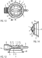
- an advantageously used optical sensor which is arranged within the sensor unit 12, has, as in Fig. 11 is shown schematically, an emitter 18 and an optical receiver (receiver) 19 on.
- the two projections 17 are used for mechanical fixation of the optical sensor unit 12.
- the emitter 18 and the receiver 19 are arranged such that an optical beam path 21, as in Fig. 11 represented over the Wandungsabêt 8 to the present in the flow channel 2 and the rest of the interior, in particular flowing urea solution and from there by reflection to the receiver 19 is passed when the sensor unit 12 is completely inserted into the receiving housing 9.
- a recess 20 for receiving one of the projections 17 of the optical sensor unit 12 is integrally formed in a bottom portion 28 of the receiving housing 9 on both sides of the permeable wall portion 8, in particular of the opening.
- a shoulder formed on which a peripheral seal 22 is mounted which is preferably designed as an elastically deformable O-ring seal.
- the sensor unit 12 has on the outer circumference of its peripheral wall 14 perpendicular to this aligned, web-shaped extensions 24, which are preferably arcuate and diametrically opposed, see Fig. 6 .
- the receiving housing 9 in the inserted state of the sensor unit 12, the web-shaped projections 24 of the sensor unit 12 opposite, arcuate web-shaped extensions 26, see Fig. 5 In the region of these web-shaped projections 24, 26 of the sensor unit 12 and the receiving housing 9, the sensor unit 12 in the assembled state with the receiving housing 9, as already stated, be connected either cohesively or positively.
- an electric heater 7 is formed from there heating elements, which serves for heating the fluid flowing in the connector piece 1, ie, the urea solution.
- the heating elements are formed from an electrically conductive conductor wire 27.
- This conductor wire 27 extends in the region between the terminal sections 3, 4 on the outside of the connector piece 1, in particular on the outside of the receiving housing 9, on the outside of the bottom portion 28 of the receiving housing 9.
- the conductor wire 27 runs meandering parallel to the bottom portion 28, and in the region of the cylindrical portions 29 of the connector piece 1 lying between the bottom portion 28 and the terminal portions 3, 4, the conductor wire 27 extends circumferentially around the cylindrical portions 29 spirally wound around.
- the free ends of the conductor wire 27 are in particular guided such that they can be electrically connected to externally supplied electrical supply conductors, for example by clamping means. It is also within the scope of the invention if the conductor wire 27 located on the connector piece 1 is a continuation of an electrical heating conductor 37 which is on a media line 6 connected to the line connector or to the connector piece 1. The conductor wire 27 located on the connector piece 1 can be connected in series or in parallel with the electrical heating conductor 37 arranged on a connected media line 6, via a corresponding electrical clamping or soldering connection.
- the terminal portion 3 is formed as a connecting pin on which a flexible media line 6 is plugged, as shown in FIG Fig. 8 can be seen.
- the connecting portion 3 is formed as a socket-like receiving element into which a media line 6, in particular a conduit, can be inserted, and a material connection between the inserted pipe and the socket-like receiving element, for example by a laser welding.
- Fig. 10 an embodiment is shown, in which the connecting portion 3 is formed as an SAE connection in the form of a tubular connecting piece, on which a media line 6 is plugged and secured, for example, with a clamp.
- the connecting portion 4 is shown in the illustrated embodiments as a sleeve portion with releasing elements 33 formed thereon, so that a male element, such as a plug, can be used arresting in this sleeve part and this is fixed via the release elements 33.
- the release elements 33 are actuated, for example, spread, and the male member can be pulled out of the sleeve portion.
- the connector piece 1 starting from the provided with the release elements 33 connecting portion 4 to over the region of the opposite terminal portion 3, namely this connection portion in the longitudinal direction across, of an encapsulation 34, in particular of plastic , is enclosed.
- an encapsulation 34 in particular of plastic
- this housing may be configured such that it serves a chamber for receiving electrical connection connectors between the ends of the heating elements 7 located on the connector piece 1 and the ends of externally inserted electrical connection conductors and possibly of the ends of heating conductors of a connected media line.
- an encapsulation 34 can be formed from two housing shells, so that a housing is formed therefrom, wherein the housing shells are connected to one another by means of latching means, in particular also detachably.
- FIG. 12 an alternative embodiment of the flow channel 2 is shown.
- the flow cross section of the flow channel 2 with respect to the flow cross section of the flow channel in the connection section 3 is reduced.
- This also applies to the flow channel of an inserted into the receiving opening 4a of the terminal portion 4 plug part.
- an increase in speed in the region of the flow channel 2 of the flowing medium and in particular in the region of the measuring point is achieved, namely with respect to the flow velocity in the flow channel of the connection section 3 and in the flow channel of the inserted into the receiving opening 4a plug part.
- the flow velocity of the flowing medium is increased and this ensures that existing Air bubbles no longer accumulate in the area of the measuring point, but are washed away by it. Thus, it is no longer possible to influence the measuring accuracy by such air bubbles.
- an overall cross-section of the flow section below the sensor measuring point which is formed by the flow cross-section of the flow channel 2 and the region which also flows through the medium, is 60% to 75% of the flow cross-section (inlet cross-section) in the connection section 3.
- this z. B. is 1/3 of the flow cross section in the connection section 3. Is the diameter of the flow channel in the connection section 3 z. B. 6 mm, the diameter of the flow channel 2 below the sensor measuring point z. B. 2 mm.
- the reduction of the flow cross section of the flow channel 2 is expediently achieved by increasing the wall thickness of the wall between the connection sections 3, 4.
- the transition between the flow channel in the connection section 3 and that in the connection section 4 takes place continuously, for example, via inclined surfaces 2a.
- the functional design of the flow channel 2 described above is based on the basic teaching according to the invention that at measuring points at which the properties of flowing media are measured by means of sensors, in particular optical sensors, the flow rate is expediently to be increased in such a way, and with respect to the flow velocity of medium to be measured in front of and behind the respective measuring point that accumulations of air bubbles or other particles influencing the measurement can not occur in the area of the measuring point.
- it is expedient if there is no sudden transition between the different flow cross sections, but a continuous one Transition between the flow cross sections, so that thereby also a homogenization of the flow is effected. It is expedient if, for example, a Venturidüsen shame training is realized.
- an optical sensor for measuring the properties of a medium, in particular a liquid medium, for example an SCR solution, by existing ambient light.
- a medium in particular a liquid medium, for example an SCR solution
- existing ambient light in the region of the measuring point, the material surrounding the measuring sensors, in particular plastic, for example the existing counter-contour to the measuring device or existing covers, formed such that it for the wavelength of the ambient light, in particular for existing UV and / or IR radiation, impermeable is.
- the material surrounding the measuring sensor for laser radiation would be transparent.
- a line connector according to the invention may be part of a ready-made media line, so that the connector piece 1 is connected, for example in the region of its connection section 3, to a media line 6 fastened thereon.
- This media line 6 may be enclosed by an outer tubular sheath 36, which may in particular be a ring-corrugated tube.
- this tube is inserted into the housing 34 at one end and can be positively connected to the housing 34.
- Fig. 10 is a so-called "stand-alone" variant of a line connector according to the invention shown by way of example.
- the housing 34 extends between the exposed terminal portion 4 and the transition of the terminal portion 3 to the cylindrical portion 29, so that the terminal portion 3 is exposed, and is formed, for example, as an SAE terminal.
- Housing 34 has a chamber extending the length of the heated area for receiving the electrical leads and the electrical connections between the leads and the electrical conductor for heating the connector plug.
- connection sections 3 are formed on both sides with connection sections 3, as described above.
- the line connector according to the invention may be formed as an angled conduit connector.
- the invention is not limited to the illustrated and described embodiments, but also includes all the same in the context of the invention embodiments. It is expressly emphasized that the exemplary embodiments are not limited to all the features in combination, but rather each individual partial feature may also have an inventive meaning independently of all other partial features. Furthermore, the invention is not yet limited to the feature combination defined in claim 1, but can also by any other combination of certain characteristics of all individual features disclosed. This means that in principle virtually every single feature of claim 1 can be omitted or replaced by at least one individual feature disclosed elsewhere in the application.
Landscapes
- Engineering & Computer Science (AREA)
- General Engineering & Computer Science (AREA)
- Mechanical Engineering (AREA)
- Exhaust Gas After Treatment (AREA)
- Optical Measuring Cells (AREA)
Priority Applications (2)
| Application Number | Priority Date | Filing Date | Title |
|---|---|---|---|
| US16/201,127 US10590825B2 (en) | 2017-11-27 | 2018-11-27 | Line connector with integrated sensor for measurement of urea solutions |
| CN201811424385.9A CN109838634B (zh) | 2017-11-27 | 2018-11-27 | 带有集成的用于测量尿素溶液的传感器的线路连接器 |
Applications Claiming Priority (1)
| Application Number | Priority Date | Filing Date | Title |
|---|---|---|---|
| DE102017127936.9A DE102017127936A1 (de) | 2017-11-27 | 2017-11-27 | Leitungsverbinder mit integriertem Sensor zur Messung von Harnstoff-Lösungen |
Publications (2)
| Publication Number | Publication Date |
|---|---|
| EP3495706A1 true EP3495706A1 (fr) | 2019-06-12 |
| EP3495706B1 EP3495706B1 (fr) | 2020-07-22 |
Family
ID=64477025
Family Applications (1)
| Application Number | Title | Priority Date | Filing Date |
|---|---|---|---|
| EP18208326.1A Active EP3495706B1 (fr) | 2017-11-27 | 2018-11-26 | Raccord de conduite à capteur intégré permettant de mesurer des solutions d'urée |
Country Status (3)
| Country | Link |
|---|---|
| EP (1) | EP3495706B1 (fr) |
| CN (1) | CN109838634B (fr) |
| DE (1) | DE102017127936A1 (fr) |
Citations (5)
| Publication number | Priority date | Publication date | Assignee | Title |
|---|---|---|---|---|
| WO2007019577A2 (fr) * | 2005-08-08 | 2007-02-15 | Siemens Vdo Automotive Corporation | Capteur detectant la qualite d'un fluide |
| WO2008131993A1 (fr) * | 2007-04-26 | 2008-11-06 | Voss Automotive Gmbh | Raccord pour conduites d'acheminement de substances |
| WO2012079833A1 (fr) * | 2010-12-15 | 2012-06-21 | Contitech Schlauch Gmbh | Dispositif de raccordement pouvant être chauffé pour tuyaux conduisant des fluides pouvant être chauffés électriquement |
| EP2527704A1 (fr) * | 2011-05-20 | 2012-11-28 | NORMA Germany GmbH | Connecteur pour une conduite de fluide et conduite de fluide |
| US20130220467A1 (en) * | 2012-02-28 | 2013-08-29 | Norma U.S. Holding Llc | Automotive selective catalytic reduction (scr) system sensor holder and assembly |
Family Cites Families (5)
| Publication number | Priority date | Publication date | Assignee | Title |
|---|---|---|---|---|
| DE202007015036U1 (de) * | 2007-10-26 | 2009-03-12 | Voss Automotive Gmbh | Leitungsverbinder sowie Leitungssatz für fluidische Medien |
| JP5172545B2 (ja) * | 2008-09-01 | 2013-03-27 | ヤンマー株式会社 | 過給機の冷却構造 |
| CN103372706A (zh) * | 2012-04-18 | 2013-10-30 | Stx造船海洋株式会社 | 利用光通信的scr熔接器 |
| CN204831420U (zh) * | 2015-08-26 | 2015-12-02 | 浙江嘉康电子股份有限公司 | 一种超声波流量传感器装配结构件 |
| CN107166104A (zh) * | 2017-06-29 | 2017-09-15 | 安徽省含山县伟峰通用配件铸造厂 | 一种湿度控制管件 |
-
2017
- 2017-11-27 DE DE102017127936.9A patent/DE102017127936A1/de active Pending
-
2018
- 2018-11-26 EP EP18208326.1A patent/EP3495706B1/fr active Active
- 2018-11-27 CN CN201811424385.9A patent/CN109838634B/zh active Active
Patent Citations (6)
| Publication number | Priority date | Publication date | Assignee | Title |
|---|---|---|---|---|
| WO2007019577A2 (fr) * | 2005-08-08 | 2007-02-15 | Siemens Vdo Automotive Corporation | Capteur detectant la qualite d'un fluide |
| WO2008131993A1 (fr) * | 2007-04-26 | 2008-11-06 | Voss Automotive Gmbh | Raccord pour conduites d'acheminement de substances |
| EP2137449B1 (fr) | 2007-04-26 | 2011-06-15 | Voss Automotive GmbH | Raccord pour conduites d'acheminement de substances |
| WO2012079833A1 (fr) * | 2010-12-15 | 2012-06-21 | Contitech Schlauch Gmbh | Dispositif de raccordement pouvant être chauffé pour tuyaux conduisant des fluides pouvant être chauffés électriquement |
| EP2527704A1 (fr) * | 2011-05-20 | 2012-11-28 | NORMA Germany GmbH | Connecteur pour une conduite de fluide et conduite de fluide |
| US20130220467A1 (en) * | 2012-02-28 | 2013-08-29 | Norma U.S. Holding Llc | Automotive selective catalytic reduction (scr) system sensor holder and assembly |
Also Published As
| Publication number | Publication date |
|---|---|
| CN109838634B (zh) | 2021-08-10 |
| EP3495706B1 (fr) | 2020-07-22 |
| CN109838634A (zh) | 2019-06-04 |
| DE102017127936A1 (de) | 2019-05-29 |
Similar Documents
| Publication | Publication Date | Title |
|---|---|---|
| DE102011102244B4 (de) | Verbinder für eine beheizbare Fluidleitung und beheizbare Fluidleitung | |
| EP2527703B1 (fr) | Conduite de fluide | |
| DE102011102151B4 (de) | Fluidleitung | |
| DE202007010502U1 (de) | Konfektionierte Medienleitung | |
| DE102015117508A1 (de) | Elektrisches Kabel mit einer Fluidleitung zum Kühlen | |
| DE102014005817A1 (de) | Mehrteilige beheizbare Medienleitung, Leitungsverbindungseinrichtung für eine solche sowie Verfahren zum Herstellen einer solchen | |
| DE102007056544A1 (de) | Sensoranordnung zur Bestimmung eines Tankfüllstands und Verfahren zur Herstellung hierzu | |
| WO2011151008A1 (fr) | Conduite, pouvant être chauffée, pour fluides, en particulier pour fluides de processus d'une installation de piles à combustible et installation de piles à combustible | |
| DE19644757A1 (de) | Meßeinrichtung | |
| DE102010034786A1 (de) | Ultraschalldurchflussmesser mit Universal-Sensorträger | |
| DE102008006323B4 (de) | Reduktionsmittelversorgungssystem für einen Abgasreinigungskatalysator eines Verbrennungsmotors und Steckverbindung zum Anschließen von beheizbaren Flüssigkeitsleitungen | |
| DE202011100991U1 (de) | Medienleitung | |
| DE10040739B4 (de) | Sensor zur Bestimmung des Niveaus und der Temperatur einer Fllüssigkeit | |
| DE202014105908U1 (de) | Beheizungssystem für eine fluidführende Leitung | |
| EP3495706B1 (fr) | Raccord de conduite à capteur intégré permettant de mesurer des solutions d'urée | |
| DE102009010637A1 (de) | Vorrichtung zur Durchflussmessung | |
| EP2071300A2 (fr) | Réservoir avec des éléments électriques couverts au moins partiellement avec un élastomère | |
| DE4218170C1 (fr) | ||
| DE202008007392U1 (de) | Fluidleitung und Leitungsverbinder zum Führen und Beheizen eines Mediums | |
| EP2215436B1 (fr) | Ensemble capteur pour déterminer le niveau dans un réservoir et réservoir muni d'un tel ensemble capteur | |
| EP3139138A1 (fr) | Vanne de debitmetre | |
| DE202012101468U1 (de) | Medienleitung, insbesondere zum Transport von Harnstoff-Wasser-Lösungen | |
| DE102005046809B4 (de) | Vorrichtung zur Behandlung von Flüssigkeiten | |
| DE19616354C2 (de) | Rohrleitungsstück mit elektrischer Leitung | |
| DE102013207630A1 (de) | Optischer Sensor |
Legal Events
| Date | Code | Title | Description |
|---|---|---|---|
| PUAI | Public reference made under article 153(3) epc to a published international application that has entered the european phase |
Free format text: ORIGINAL CODE: 0009012 |
|
| STAA | Information on the status of an ep patent application or granted ep patent |
Free format text: STATUS: THE APPLICATION HAS BEEN PUBLISHED |
|
| AK | Designated contracting states |
Kind code of ref document: A1 Designated state(s): AL AT BE BG CH CY CZ DE DK EE ES FI FR GB GR HR HU IE IS IT LI LT LU LV MC MK MT NL NO PL PT RO RS SE SI SK SM TR |
|
| AX | Request for extension of the european patent |
Extension state: BA ME |
|
| STAA | Information on the status of an ep patent application or granted ep patent |
Free format text: STATUS: REQUEST FOR EXAMINATION WAS MADE |
|
| 17P | Request for examination filed |
Effective date: 20191127 |
|
| RBV | Designated contracting states (corrected) |
Designated state(s): AL AT BE BG CH CY CZ DE DK EE ES FI FR GB GR HR HU IE IS IT LI LT LU LV MC MK MT NL NO PL PT RO RS SE SI SK SM TR |
|
| GRAP | Despatch of communication of intention to grant a patent |
Free format text: ORIGINAL CODE: EPIDOSNIGR1 |
|
| STAA | Information on the status of an ep patent application or granted ep patent |
Free format text: STATUS: GRANT OF PATENT IS INTENDED |
|
| INTG | Intention to grant announced |
Effective date: 20200225 |
|
| RIN1 | Information on inventor provided before grant (corrected) |
Inventor name: ZWILLUS, CHRISTIAN Inventor name: INNIGER, STEVE Inventor name: ROSENFELDT, SASCHA Inventor name: WILMS, WALDEMAR |
|
| GRAS | Grant fee paid |
Free format text: ORIGINAL CODE: EPIDOSNIGR3 |
|
| GRAA | (expected) grant |
Free format text: ORIGINAL CODE: 0009210 |
|
| STAA | Information on the status of an ep patent application or granted ep patent |
Free format text: STATUS: THE PATENT HAS BEEN GRANTED |
|
| AK | Designated contracting states |
Kind code of ref document: B1 Designated state(s): AL AT BE BG CH CY CZ DE DK EE ES FI FR GB GR HR HU IE IS IT LI LT LU LV MC MK MT NL NO PL PT RO RS SE SI SK SM TR |
|
| REG | Reference to a national code |
Ref country code: GB Ref legal event code: FG4D Free format text: NOT ENGLISH |
|
| REG | Reference to a national code |
Ref country code: CH Ref legal event code: EP |
|
| REG | Reference to a national code |
Ref country code: DE Ref legal event code: R096 Ref document number: 502018001948 Country of ref document: DE |
|
| REG | Reference to a national code |
Ref country code: AT Ref legal event code: REF Ref document number: 1293717 Country of ref document: AT Kind code of ref document: T Effective date: 20200815 |
|
| REG | Reference to a national code |
Ref country code: IE Ref legal event code: FG4D Free format text: LANGUAGE OF EP DOCUMENT: GERMAN |
|
| REG | Reference to a national code |
Ref country code: LT Ref legal event code: MG4D |
|
| PG25 | Lapsed in a contracting state [announced via postgrant information from national office to epo] |
Ref country code: BG Free format text: LAPSE BECAUSE OF FAILURE TO SUBMIT A TRANSLATION OF THE DESCRIPTION OR TO PAY THE FEE WITHIN THE PRESCRIBED TIME-LIMIT Effective date: 20201022 Ref country code: SE Free format text: LAPSE BECAUSE OF FAILURE TO SUBMIT A TRANSLATION OF THE DESCRIPTION OR TO PAY THE FEE WITHIN THE PRESCRIBED TIME-LIMIT Effective date: 20200722 Ref country code: GR Free format text: LAPSE BECAUSE OF FAILURE TO SUBMIT A TRANSLATION OF THE DESCRIPTION OR TO PAY THE FEE WITHIN THE PRESCRIBED TIME-LIMIT Effective date: 20201023 Ref country code: ES Free format text: LAPSE BECAUSE OF FAILURE TO SUBMIT A TRANSLATION OF THE DESCRIPTION OR TO PAY THE FEE WITHIN THE PRESCRIBED TIME-LIMIT Effective date: 20200722 Ref country code: PT Free format text: LAPSE BECAUSE OF FAILURE TO SUBMIT A TRANSLATION OF THE DESCRIPTION OR TO PAY THE FEE WITHIN THE PRESCRIBED TIME-LIMIT Effective date: 20201123 Ref country code: NO Free format text: LAPSE BECAUSE OF FAILURE TO SUBMIT A TRANSLATION OF THE DESCRIPTION OR TO PAY THE FEE WITHIN THE PRESCRIBED TIME-LIMIT Effective date: 20201022 Ref country code: FI Free format text: LAPSE BECAUSE OF FAILURE TO SUBMIT A TRANSLATION OF THE DESCRIPTION OR TO PAY THE FEE WITHIN THE PRESCRIBED TIME-LIMIT Effective date: 20200722 Ref country code: LT Free format text: LAPSE BECAUSE OF FAILURE TO SUBMIT A TRANSLATION OF THE DESCRIPTION OR TO PAY THE FEE WITHIN THE PRESCRIBED TIME-LIMIT Effective date: 20200722 Ref country code: HR Free format text: LAPSE BECAUSE OF FAILURE TO SUBMIT A TRANSLATION OF THE DESCRIPTION OR TO PAY THE FEE WITHIN THE PRESCRIBED TIME-LIMIT Effective date: 20200722 |
|
| PG25 | Lapsed in a contracting state [announced via postgrant information from national office to epo] |
Ref country code: RS Free format text: LAPSE BECAUSE OF FAILURE TO SUBMIT A TRANSLATION OF THE DESCRIPTION OR TO PAY THE FEE WITHIN THE PRESCRIBED TIME-LIMIT Effective date: 20200722 Ref country code: PL Free format text: LAPSE BECAUSE OF FAILURE TO SUBMIT A TRANSLATION OF THE DESCRIPTION OR TO PAY THE FEE WITHIN THE PRESCRIBED TIME-LIMIT Effective date: 20200722 Ref country code: LV Free format text: LAPSE BECAUSE OF FAILURE TO SUBMIT A TRANSLATION OF THE DESCRIPTION OR TO PAY THE FEE WITHIN THE PRESCRIBED TIME-LIMIT Effective date: 20200722 Ref country code: IS Free format text: LAPSE BECAUSE OF FAILURE TO SUBMIT A TRANSLATION OF THE DESCRIPTION OR TO PAY THE FEE WITHIN THE PRESCRIBED TIME-LIMIT Effective date: 20201122 |
|
| PG25 | Lapsed in a contracting state [announced via postgrant information from national office to epo] |
Ref country code: NL Free format text: LAPSE BECAUSE OF FAILURE TO SUBMIT A TRANSLATION OF THE DESCRIPTION OR TO PAY THE FEE WITHIN THE PRESCRIBED TIME-LIMIT Effective date: 20200722 |
|
| REG | Reference to a national code |
Ref country code: DE Ref legal event code: R097 Ref document number: 502018001948 Country of ref document: DE |
|
| PG25 | Lapsed in a contracting state [announced via postgrant information from national office to epo] |
Ref country code: SM Free format text: LAPSE BECAUSE OF FAILURE TO SUBMIT A TRANSLATION OF THE DESCRIPTION OR TO PAY THE FEE WITHIN THE PRESCRIBED TIME-LIMIT Effective date: 20200722 Ref country code: EE Free format text: LAPSE BECAUSE OF FAILURE TO SUBMIT A TRANSLATION OF THE DESCRIPTION OR TO PAY THE FEE WITHIN THE PRESCRIBED TIME-LIMIT Effective date: 20200722 Ref country code: RO Free format text: LAPSE BECAUSE OF FAILURE TO SUBMIT A TRANSLATION OF THE DESCRIPTION OR TO PAY THE FEE WITHIN THE PRESCRIBED TIME-LIMIT Effective date: 20200722 Ref country code: CZ Free format text: LAPSE BECAUSE OF FAILURE TO SUBMIT A TRANSLATION OF THE DESCRIPTION OR TO PAY THE FEE WITHIN THE PRESCRIBED TIME-LIMIT Effective date: 20200722 Ref country code: DK Free format text: LAPSE BECAUSE OF FAILURE TO SUBMIT A TRANSLATION OF THE DESCRIPTION OR TO PAY THE FEE WITHIN THE PRESCRIBED TIME-LIMIT Effective date: 20200722 |
|
| PLBE | No opposition filed within time limit |
Free format text: ORIGINAL CODE: 0009261 |
|
| STAA | Information on the status of an ep patent application or granted ep patent |
Free format text: STATUS: NO OPPOSITION FILED WITHIN TIME LIMIT |
|
| PG25 | Lapsed in a contracting state [announced via postgrant information from national office to epo] |
Ref country code: AL Free format text: LAPSE BECAUSE OF FAILURE TO SUBMIT A TRANSLATION OF THE DESCRIPTION OR TO PAY THE FEE WITHIN THE PRESCRIBED TIME-LIMIT Effective date: 20200722 |
|
| 26N | No opposition filed |
Effective date: 20210423 |
|
| PG25 | Lapsed in a contracting state [announced via postgrant information from national office to epo] |
Ref country code: SK Free format text: LAPSE BECAUSE OF FAILURE TO SUBMIT A TRANSLATION OF THE DESCRIPTION OR TO PAY THE FEE WITHIN THE PRESCRIBED TIME-LIMIT Effective date: 20200722 Ref country code: MC Free format text: LAPSE BECAUSE OF FAILURE TO SUBMIT A TRANSLATION OF THE DESCRIPTION OR TO PAY THE FEE WITHIN THE PRESCRIBED TIME-LIMIT Effective date: 20200722 |
|
| PG25 | Lapsed in a contracting state [announced via postgrant information from national office to epo] |
Ref country code: LU Free format text: LAPSE BECAUSE OF NON-PAYMENT OF DUE FEES Effective date: 20201126 |
|
| REG | Reference to a national code |
Ref country code: BE Ref legal event code: MM Effective date: 20201130 |
|
| PG25 | Lapsed in a contracting state [announced via postgrant information from national office to epo] |
Ref country code: SI Free format text: LAPSE BECAUSE OF FAILURE TO SUBMIT A TRANSLATION OF THE DESCRIPTION OR TO PAY THE FEE WITHIN THE PRESCRIBED TIME-LIMIT Effective date: 20200722 |
|
| REG | Reference to a national code |
Ref country code: NL Ref legal event code: MP Effective date: 20200722 |
|
| PG25 | Lapsed in a contracting state [announced via postgrant information from national office to epo] |
Ref country code: IE Free format text: LAPSE BECAUSE OF NON-PAYMENT OF DUE FEES Effective date: 20201126 |
|
| PG25 | Lapsed in a contracting state [announced via postgrant information from national office to epo] |
Ref country code: TR Free format text: LAPSE BECAUSE OF FAILURE TO SUBMIT A TRANSLATION OF THE DESCRIPTION OR TO PAY THE FEE WITHIN THE PRESCRIBED TIME-LIMIT Effective date: 20200722 Ref country code: MT Free format text: LAPSE BECAUSE OF FAILURE TO SUBMIT A TRANSLATION OF THE DESCRIPTION OR TO PAY THE FEE WITHIN THE PRESCRIBED TIME-LIMIT Effective date: 20200722 Ref country code: CY Free format text: LAPSE BECAUSE OF FAILURE TO SUBMIT A TRANSLATION OF THE DESCRIPTION OR TO PAY THE FEE WITHIN THE PRESCRIBED TIME-LIMIT Effective date: 20200722 |
|
| PG25 | Lapsed in a contracting state [announced via postgrant information from national office to epo] |
Ref country code: MK Free format text: LAPSE BECAUSE OF FAILURE TO SUBMIT A TRANSLATION OF THE DESCRIPTION OR TO PAY THE FEE WITHIN THE PRESCRIBED TIME-LIMIT Effective date: 20200722 |
|
| REG | Reference to a national code |
Ref country code: CH Ref legal event code: PL |
|
| PG25 | Lapsed in a contracting state [announced via postgrant information from national office to epo] |
Ref country code: BE Free format text: LAPSE BECAUSE OF NON-PAYMENT OF DUE FEES Effective date: 20201130 |
|
| P01 | Opt-out of the competence of the unified patent court (upc) registered |
Effective date: 20230526 |
|
| GBPC | Gb: european patent ceased through non-payment of renewal fee |
Effective date: 20221126 |
|
| PG25 | Lapsed in a contracting state [announced via postgrant information from national office to epo] |
Ref country code: LI Free format text: LAPSE BECAUSE OF NON-PAYMENT OF DUE FEES Effective date: 20220630 Ref country code: CH Free format text: LAPSE BECAUSE OF NON-PAYMENT OF DUE FEES Effective date: 20220630 |
|
| PG25 | Lapsed in a contracting state [announced via postgrant information from national office to epo] |
Ref country code: GB Free format text: LAPSE BECAUSE OF NON-PAYMENT OF DUE FEES Effective date: 20221126 |
|
| PGFP | Annual fee paid to national office [announced via postgrant information from national office to epo] |
Ref country code: IT Payment date: 20231018 Year of fee payment: 6 Ref country code: FR Payment date: 20231011 Year of fee payment: 6 |
|
| PGFP | Annual fee paid to national office [announced via postgrant information from national office to epo] |
Ref country code: DE Payment date: 20240126 Year of fee payment: 6 |