EP3495187A1 - Attention attracting device for vehicle - Google Patents
Attention attracting device for vehicle Download PDFInfo
- Publication number
- EP3495187A1 EP3495187A1 EP18205737.2A EP18205737A EP3495187A1 EP 3495187 A1 EP3495187 A1 EP 3495187A1 EP 18205737 A EP18205737 A EP 18205737A EP 3495187 A1 EP3495187 A1 EP 3495187A1
- Authority
- EP
- European Patent Office
- Prior art keywords
- vibration
- information
- attention
- host vehicle
- attention information
- Prior art date
- Legal status (The legal status is an assumption and is not a legal conclusion. Google has not performed a legal analysis and makes no representation as to the accuracy of the status listed.)
- Granted
Links
Images





Classifications
-
- B—PERFORMING OPERATIONS; TRANSPORTING
- B60—VEHICLES IN GENERAL
- B60R—VEHICLES, VEHICLE FITTINGS, OR VEHICLE PARTS, NOT OTHERWISE PROVIDED FOR
- B60R21/00—Arrangements or fittings on vehicles for protecting or preventing injuries to occupants or pedestrians in case of accidents or other traffic risks
-
- B—PERFORMING OPERATIONS; TRANSPORTING
- B60—VEHICLES IN GENERAL
- B60W—CONJOINT CONTROL OF VEHICLE SUB-UNITS OF DIFFERENT TYPE OR DIFFERENT FUNCTION; CONTROL SYSTEMS SPECIALLY ADAPTED FOR HYBRID VEHICLES; ROAD VEHICLE DRIVE CONTROL SYSTEMS FOR PURPOSES NOT RELATED TO THE CONTROL OF A PARTICULAR SUB-UNIT
- B60W50/00—Details of control systems for road vehicle drive control not related to the control of a particular sub-unit, e.g. process diagnostic or vehicle driver interfaces
- B60W50/08—Interaction between the driver and the control system
- B60W50/14—Means for informing the driver, warning the driver or prompting a driver intervention
- B60W50/16—Tactile feedback to the driver, e.g. vibration or force feedback to the driver on the steering wheel or the accelerator pedal
-
- B—PERFORMING OPERATIONS; TRANSPORTING
- B60—VEHICLES IN GENERAL
- B60N—SEATS SPECIALLY ADAPTED FOR VEHICLES; VEHICLE PASSENGER ACCOMMODATION NOT OTHERWISE PROVIDED FOR
- B60N2/00—Seats specially adapted for vehicles; Arrangement or mounting of seats in vehicles
-
- B—PERFORMING OPERATIONS; TRANSPORTING
- B60—VEHICLES IN GENERAL
- B60Q—ARRANGEMENT OF SIGNALLING OR LIGHTING DEVICES, THE MOUNTING OR SUPPORTING THEREOF OR CIRCUITS THEREFOR, FOR VEHICLES IN GENERAL
- B60Q9/00—Arrangement or adaptation of signal devices not provided for in one of main groups B60Q1/00 - B60Q7/00, e.g. haptic signalling
-
- B—PERFORMING OPERATIONS; TRANSPORTING
- B60—VEHICLES IN GENERAL
- B60K—ARRANGEMENT OR MOUNTING OF PROPULSION UNITS OR OF TRANSMISSIONS IN VEHICLES; ARRANGEMENT OR MOUNTING OF PLURAL DIVERSE PRIME-MOVERS IN VEHICLES; AUXILIARY DRIVES FOR VEHICLES; INSTRUMENTATION OR DASHBOARDS FOR VEHICLES; ARRANGEMENTS IN CONNECTION WITH COOLING, AIR INTAKE, GAS EXHAUST OR FUEL SUPPLY OF PROPULSION UNITS IN VEHICLES
- B60K35/00—Instruments specially adapted for vehicles; Arrangement of instruments in or on vehicles
- B60K35/10—Input arrangements, i.e. from user to vehicle, associated with vehicle functions or specially adapted therefor
-
- B—PERFORMING OPERATIONS; TRANSPORTING
- B60—VEHICLES IN GENERAL
- B60K—ARRANGEMENT OR MOUNTING OF PROPULSION UNITS OR OF TRANSMISSIONS IN VEHICLES; ARRANGEMENT OR MOUNTING OF PLURAL DIVERSE PRIME-MOVERS IN VEHICLES; AUXILIARY DRIVES FOR VEHICLES; INSTRUMENTATION OR DASHBOARDS FOR VEHICLES; ARRANGEMENTS IN CONNECTION WITH COOLING, AIR INTAKE, GAS EXHAUST OR FUEL SUPPLY OF PROPULSION UNITS IN VEHICLES
- B60K35/00—Instruments specially adapted for vehicles; Arrangement of instruments in or on vehicles
- B60K35/20—Output arrangements, i.e. from vehicle to user, associated with vehicle functions or specially adapted therefor
- B60K35/21—Output arrangements, i.e. from vehicle to user, associated with vehicle functions or specially adapted therefor using visual output, e.g. blinking lights or matrix displays
- B60K35/22—Display screens
-
- B—PERFORMING OPERATIONS; TRANSPORTING
- B60—VEHICLES IN GENERAL
- B60K—ARRANGEMENT OR MOUNTING OF PROPULSION UNITS OR OF TRANSMISSIONS IN VEHICLES; ARRANGEMENT OR MOUNTING OF PLURAL DIVERSE PRIME-MOVERS IN VEHICLES; AUXILIARY DRIVES FOR VEHICLES; INSTRUMENTATION OR DASHBOARDS FOR VEHICLES; ARRANGEMENTS IN CONNECTION WITH COOLING, AIR INTAKE, GAS EXHAUST OR FUEL SUPPLY OF PROPULSION UNITS IN VEHICLES
- B60K35/00—Instruments specially adapted for vehicles; Arrangement of instruments in or on vehicles
- B60K35/20—Output arrangements, i.e. from vehicle to user, associated with vehicle functions or specially adapted therefor
- B60K35/25—Output arrangements, i.e. from vehicle to user, associated with vehicle functions or specially adapted therefor using haptic output
-
- B—PERFORMING OPERATIONS; TRANSPORTING
- B60—VEHICLES IN GENERAL
- B60K—ARRANGEMENT OR MOUNTING OF PROPULSION UNITS OR OF TRANSMISSIONS IN VEHICLES; ARRANGEMENT OR MOUNTING OF PLURAL DIVERSE PRIME-MOVERS IN VEHICLES; AUXILIARY DRIVES FOR VEHICLES; INSTRUMENTATION OR DASHBOARDS FOR VEHICLES; ARRANGEMENTS IN CONNECTION WITH COOLING, AIR INTAKE, GAS EXHAUST OR FUEL SUPPLY OF PROPULSION UNITS IN VEHICLES
- B60K35/00—Instruments specially adapted for vehicles; Arrangement of instruments in or on vehicles
- B60K35/20—Output arrangements, i.e. from vehicle to user, associated with vehicle functions or specially adapted therefor
- B60K35/28—Output arrangements, i.e. from vehicle to user, associated with vehicle functions or specially adapted therefor characterised by the type of the output information, e.g. video entertainment or vehicle dynamics information; characterised by the purpose of the output information, e.g. for attracting the attention of the driver
-
- B—PERFORMING OPERATIONS; TRANSPORTING
- B60—VEHICLES IN GENERAL
- B60K—ARRANGEMENT OR MOUNTING OF PROPULSION UNITS OR OF TRANSMISSIONS IN VEHICLES; ARRANGEMENT OR MOUNTING OF PLURAL DIVERSE PRIME-MOVERS IN VEHICLES; AUXILIARY DRIVES FOR VEHICLES; INSTRUMENTATION OR DASHBOARDS FOR VEHICLES; ARRANGEMENTS IN CONNECTION WITH COOLING, AIR INTAKE, GAS EXHAUST OR FUEL SUPPLY OF PROPULSION UNITS IN VEHICLES
- B60K35/00—Instruments specially adapted for vehicles; Arrangement of instruments in or on vehicles
- B60K35/20—Output arrangements, i.e. from vehicle to user, associated with vehicle functions or specially adapted therefor
- B60K35/29—Instruments characterised by the way in which information is handled, e.g. showing information on plural displays or prioritising information according to driving conditions
-
- B—PERFORMING OPERATIONS; TRANSPORTING
- B60—VEHICLES IN GENERAL
- B60N—SEATS SPECIALLY ADAPTED FOR VEHICLES; VEHICLE PASSENGER ACCOMMODATION NOT OTHERWISE PROVIDED FOR
- B60N2/00—Seats specially adapted for vehicles; Arrangement or mounting of seats in vehicles
- B60N2/24—Seats specially adapted for vehicles; Arrangement or mounting of seats in vehicles for particular purposes or particular vehicles
- B60N2/38—Seats specially adapted for vehicles; Arrangement or mounting of seats in vehicles for particular purposes or particular vehicles specially constructed for use on tractors or like off-road vehicles
- B60N2/40—Seats specially adapted for vehicles; Arrangement or mounting of seats in vehicles for particular purposes or particular vehicles specially constructed for use on tractors or like off-road vehicles saddle type
-
- B—PERFORMING OPERATIONS; TRANSPORTING
- B60—VEHICLES IN GENERAL
- B60N—SEATS SPECIALLY ADAPTED FOR VEHICLES; VEHICLE PASSENGER ACCOMMODATION NOT OTHERWISE PROVIDED FOR
- B60N2/00—Seats specially adapted for vehicles; Arrangement or mounting of seats in vehicles
- B60N2/90—Details or parts not otherwise provided for
-
- B—PERFORMING OPERATIONS; TRANSPORTING
- B60—VEHICLES IN GENERAL
- B60Q—ARRANGEMENT OF SIGNALLING OR LIGHTING DEVICES, THE MOUNTING OR SUPPORTING THEREOF OR CIRCUITS THEREFOR, FOR VEHICLES IN GENERAL
- B60Q9/00—Arrangement or adaptation of signal devices not provided for in one of main groups B60Q1/00 - B60Q7/00, e.g. haptic signalling
- B60Q9/002—Arrangement or adaptation of signal devices not provided for in one of main groups B60Q1/00 - B60Q7/00, e.g. haptic signalling for parking purposes, e.g. for warning the driver that his vehicle has contacted or is about to contact an obstacle
- B60Q9/004—Arrangement or adaptation of signal devices not provided for in one of main groups B60Q1/00 - B60Q7/00, e.g. haptic signalling for parking purposes, e.g. for warning the driver that his vehicle has contacted or is about to contact an obstacle using wave sensors
- B60Q9/006—Arrangement or adaptation of signal devices not provided for in one of main groups B60Q1/00 - B60Q7/00, e.g. haptic signalling for parking purposes, e.g. for warning the driver that his vehicle has contacted or is about to contact an obstacle using wave sensors using a distance sensor
-
- B—PERFORMING OPERATIONS; TRANSPORTING
- B60—VEHICLES IN GENERAL
- B60Q—ARRANGEMENT OF SIGNALLING OR LIGHTING DEVICES, THE MOUNTING OR SUPPORTING THEREOF OR CIRCUITS THEREFOR, FOR VEHICLES IN GENERAL
- B60Q9/00—Arrangement or adaptation of signal devices not provided for in one of main groups B60Q1/00 - B60Q7/00, e.g. haptic signalling
- B60Q9/008—Arrangement or adaptation of signal devices not provided for in one of main groups B60Q1/00 - B60Q7/00, e.g. haptic signalling for anti-collision purposes
-
- B—PERFORMING OPERATIONS; TRANSPORTING
- B60—VEHICLES IN GENERAL
- B60R—VEHICLES, VEHICLE FITTINGS, OR VEHICLE PARTS, NOT OTHERWISE PROVIDED FOR
- B60R21/00—Arrangements or fittings on vehicles for protecting or preventing injuries to occupants or pedestrians in case of accidents or other traffic risks
- B60R21/01—Electrical circuits for triggering passive safety arrangements, e.g. airbags, safety belt tighteners, in case of vehicle accidents or impending vehicle accidents
- B60R21/013—Electrical circuits for triggering passive safety arrangements, e.g. airbags, safety belt tighteners, in case of vehicle accidents or impending vehicle accidents including means for detecting collisions, impending collisions or roll-over
- B60R21/0134—Electrical circuits for triggering passive safety arrangements, e.g. airbags, safety belt tighteners, in case of vehicle accidents or impending vehicle accidents including means for detecting collisions, impending collisions or roll-over responsive to imminent contact with an obstacle, e.g. using radar systems
-
- B—PERFORMING OPERATIONS; TRANSPORTING
- B60—VEHICLES IN GENERAL
- B60W—CONJOINT CONTROL OF VEHICLE SUB-UNITS OF DIFFERENT TYPE OR DIFFERENT FUNCTION; CONTROL SYSTEMS SPECIALLY ADAPTED FOR HYBRID VEHICLES; ROAD VEHICLE DRIVE CONTROL SYSTEMS FOR PURPOSES NOT RELATED TO THE CONTROL OF A PARTICULAR SUB-UNIT
- B60W30/00—Purposes of road vehicle drive control systems not related to the control of a particular sub-unit, e.g. of systems using conjoint control of vehicle sub-units
- B60W30/18—Propelling the vehicle
- B60W30/18009—Propelling the vehicle related to particular drive situations
- B60W30/18163—Lane change; Overtaking manoeuvres
-
- B—PERFORMING OPERATIONS; TRANSPORTING
- B60—VEHICLES IN GENERAL
- B60W—CONJOINT CONTROL OF VEHICLE SUB-UNITS OF DIFFERENT TYPE OR DIFFERENT FUNCTION; CONTROL SYSTEMS SPECIALLY ADAPTED FOR HYBRID VEHICLES; ROAD VEHICLE DRIVE CONTROL SYSTEMS FOR PURPOSES NOT RELATED TO THE CONTROL OF A PARTICULAR SUB-UNIT
- B60W40/00—Estimation or calculation of non-directly measurable driving parameters for road vehicle drive control systems not related to the control of a particular sub unit, e.g. by using mathematical models
- B60W40/02—Estimation or calculation of non-directly measurable driving parameters for road vehicle drive control systems not related to the control of a particular sub unit, e.g. by using mathematical models related to ambient conditions
-
- G—PHYSICS
- G08—SIGNALLING
- G08B—SIGNALLING SYSTEMS, e.g. PERSONAL CALLING SYSTEMS; ORDER TELEGRAPHS; ALARM SYSTEMS
- G08B6/00—Tactile signalling systems, e.g. tactile personal calling systems
-
- G—PHYSICS
- G08—SIGNALLING
- G08G—TRAFFIC CONTROL SYSTEMS
- G08G1/00—Traffic control systems for road vehicles
- G08G1/16—Anti-collision systems
-
- B—PERFORMING OPERATIONS; TRANSPORTING
- B60—VEHICLES IN GENERAL
- B60K—ARRANGEMENT OR MOUNTING OF PROPULSION UNITS OR OF TRANSMISSIONS IN VEHICLES; ARRANGEMENT OR MOUNTING OF PLURAL DIVERSE PRIME-MOVERS IN VEHICLES; AUXILIARY DRIVES FOR VEHICLES; INSTRUMENTATION OR DASHBOARDS FOR VEHICLES; ARRANGEMENTS IN CONNECTION WITH COOLING, AIR INTAKE, GAS EXHAUST OR FUEL SUPPLY OF PROPULSION UNITS IN VEHICLES
- B60K2360/00—Indexing scheme associated with groups B60K35/00 or B60K37/00 relating to details of instruments or dashboards
- B60K2360/16—Type of output information
- B60K2360/178—Warnings
-
- B—PERFORMING OPERATIONS; TRANSPORTING
- B60—VEHICLES IN GENERAL
- B60K—ARRANGEMENT OR MOUNTING OF PROPULSION UNITS OR OF TRANSMISSIONS IN VEHICLES; ARRANGEMENT OR MOUNTING OF PLURAL DIVERSE PRIME-MOVERS IN VEHICLES; AUXILIARY DRIVES FOR VEHICLES; INSTRUMENTATION OR DASHBOARDS FOR VEHICLES; ARRANGEMENTS IN CONNECTION WITH COOLING, AIR INTAKE, GAS EXHAUST OR FUEL SUPPLY OF PROPULSION UNITS IN VEHICLES
- B60K2360/00—Indexing scheme associated with groups B60K35/00 or B60K37/00 relating to details of instruments or dashboards
- B60K2360/16—Type of output information
- B60K2360/179—Distances to obstacles or vehicles
-
- B—PERFORMING OPERATIONS; TRANSPORTING
- B60—VEHICLES IN GENERAL
- B60K—ARRANGEMENT OR MOUNTING OF PROPULSION UNITS OR OF TRANSMISSIONS IN VEHICLES; ARRANGEMENT OR MOUNTING OF PLURAL DIVERSE PRIME-MOVERS IN VEHICLES; AUXILIARY DRIVES FOR VEHICLES; INSTRUMENTATION OR DASHBOARDS FOR VEHICLES; ARRANGEMENTS IN CONNECTION WITH COOLING, AIR INTAKE, GAS EXHAUST OR FUEL SUPPLY OF PROPULSION UNITS IN VEHICLES
- B60K2360/00—Indexing scheme associated with groups B60K35/00 or B60K37/00 relating to details of instruments or dashboards
- B60K2360/18—Information management
- B60K2360/186—Displaying information according to relevancy
- B60K2360/1868—Displaying information according to relevancy according to driving situations
-
- B—PERFORMING OPERATIONS; TRANSPORTING
- B60—VEHICLES IN GENERAL
- B60K—ARRANGEMENT OR MOUNTING OF PROPULSION UNITS OR OF TRANSMISSIONS IN VEHICLES; ARRANGEMENT OR MOUNTING OF PLURAL DIVERSE PRIME-MOVERS IN VEHICLES; AUXILIARY DRIVES FOR VEHICLES; INSTRUMENTATION OR DASHBOARDS FOR VEHICLES; ARRANGEMENTS IN CONNECTION WITH COOLING, AIR INTAKE, GAS EXHAUST OR FUEL SUPPLY OF PROPULSION UNITS IN VEHICLES
- B60K2360/00—Indexing scheme associated with groups B60K35/00 or B60K37/00 relating to details of instruments or dashboards
- B60K2360/20—Optical features of instruments
- B60K2360/21—Optical features of instruments using cameras
-
- B—PERFORMING OPERATIONS; TRANSPORTING
- B60—VEHICLES IN GENERAL
- B60N—SEATS SPECIALLY ADAPTED FOR VEHICLES; VEHICLE PASSENGER ACCOMMODATION NOT OTHERWISE PROVIDED FOR
- B60N2/00—Seats specially adapted for vehicles; Arrangement or mounting of seats in vehicles
- B60N2/90—Details or parts not otherwise provided for
- B60N2002/981—Warning systems, e.g. the seat or seat parts vibrates to warn the passenger when facing a danger
-
- B—PERFORMING OPERATIONS; TRANSPORTING
- B60—VEHICLES IN GENERAL
- B60W—CONJOINT CONTROL OF VEHICLE SUB-UNITS OF DIFFERENT TYPE OR DIFFERENT FUNCTION; CONTROL SYSTEMS SPECIALLY ADAPTED FOR HYBRID VEHICLES; ROAD VEHICLE DRIVE CONTROL SYSTEMS FOR PURPOSES NOT RELATED TO THE CONTROL OF A PARTICULAR SUB-UNIT
- B60W50/00—Details of control systems for road vehicle drive control not related to the control of a particular sub-unit, e.g. process diagnostic or vehicle driver interfaces
- B60W50/08—Interaction between the driver and the control system
- B60W50/14—Means for informing the driver, warning the driver or prompting a driver intervention
- B60W2050/146—Display means
-
- B—PERFORMING OPERATIONS; TRANSPORTING
- B60—VEHICLES IN GENERAL
- B60W—CONJOINT CONTROL OF VEHICLE SUB-UNITS OF DIFFERENT TYPE OR DIFFERENT FUNCTION; CONTROL SYSTEMS SPECIALLY ADAPTED FOR HYBRID VEHICLES; ROAD VEHICLE DRIVE CONTROL SYSTEMS FOR PURPOSES NOT RELATED TO THE CONTROL OF A PARTICULAR SUB-UNIT
- B60W2420/00—Indexing codes relating to the type of sensors based on the principle of their operation
- B60W2420/54—Audio sensitive means, e.g. ultrasound
Definitions
- the present invention relates to an attention attracting device for a vehicle.
- JP 2016-207097 A A technique for attracting attention of a vehicle occupant is known (see Japanese Patent Application Publication No. 2016-207097 ( JP 2016-207097 A )).
- the technique disclosed in JP 2016-207097 A relates to driving stimulus providing means, such as a vibrating motor attached to a seat of a host vehicle, when information on an object that may be an obstacle is detected around the host vehicle, and the information is transmitted to a driver.
- driving stimulus providing means such as a vibrating motor attached to a seat of a host vehicle
- the technique relating to driving one of the stimulus providing means attached to respective locations of the seat depending on the direction to attract attention of the driver.
- the present invention provides an attention attracting device for a vehicle configured such that a plurality of types of attention information is transmitted to a sitting occupant with vibration of a vehicular seat, the attention attracting device enabling the sitting occupant to easily understand the meaning or the content of the attention attracting information through vibration.
- An attention attracting device for a vehicle includes: an information detection unit configured to detect a plurality of types of attention information around a host vehicle; a vibration application application unit configured to apply vibration to a vehicular seat; a display unit configured to display an attention information content corresponding to each of the plurality of types of attention information; and a control unit configured to, when the information detection unit detects attention information, operate the vibration application unit and cause the display unit to display the attention information content corresponding to the detected attention information.
- the information detection unit detects a plurality of types of attention information about the periphery of the host vehicle.
- the vibration application unit can apply vibration to the vehicular seat, and the display unit can display the content of the plurality of types of attention information.
- the control unit operates the display unit, and displays on the display unit the content corresponding to the detected attention information. Accordingly, when the vehicular seat vibrates, the sitting occupant can easily understand, by viewing the display on the display unit, the meaning and the content of the information that attracts attention through vibration of the vehicular seat.
- a vibration pattern may set in accordance with the content of the attention information, and the control unit may configured to operate the vibration application unit with the vibration pattern corresponding to the content of the attention information detected by the information detection unit.
- the vibration application unit may configured to apply vibration to regions of the vehicular seat, the regions including: a right front portion to be vibrated that is a region on a seat surface side and a right front-end side of a seat cushion in the vehicular seat, a left front portion to be vibrated that is a region on the seat surface side and a left front-end side of the seat cushion in the vehicular seat, a right rear portion to be vibrated that is a region on a backrest surface side and a right upper-end side of a seatback in the vehicular seat, and a left rear portion to be vibrated that is a region on the backrest surface side and a left upper-end side of the seatback in the vehicular seat.
- the control unit may be configured to: when the information detection unit detects the attention information, and a detection position at which the information detection unit detects the attention information for the host vehicle is at least one side of a right front side, a left front side, a right rear side, and a left rear side of the host vehicle, control an operation of the vibration application unit such that the vibration application unit applies vibration to a region on a side corresponding to the detection position as seen in a plan view of the vehicle, the region being among the right front portion to be vibrated, the left front portion to be vibrated, the right rear portion to be vibrated, and the left rear portion to be vibrated; when the detection position is right in front of the host vehicle, control the operation of the vibration application unit such that the vibration application unit applies vibration to both the right front portion to be vibrated and the left front portion to be vibrated; and when the detection position is right behind the host vehicle, control the operation of the vibration application unit such that the vibration application unit applies vibration to both the right rear portion to be vibrated and the left rear portion to be vibrated.
- the vibration application unit can apply vibration to regions including the right and left front portions to be vibrated and the right and left rear portions to be vibrated.
- the right and left front portions to be vibrated and the right and left rear portions to be vibrated are provided on both the ends of the vehicular seat in a sheet front-rear direction as seen in a plan view of the vehicle.
- the control unit controls operation of the vibration application unit such that the vibration application unit applies vibration to a region on a side corresponding to the detection position as seen in a plan view of the vehicle, the region being among the right front portion to be vibrated, the left front portion to be vibrated, the right rear portion to be vibrated, and the left rear portion to be vibrated.
- the control unit controls operation of the vibration application unit such that the vibration application unit applies vibration to both the right and left front portions to be vibrated.
- the control unit controls operation of the vibration application unit such that the vibration application unit applies vibration to both the right and left rear portions to be vibrated. Therefore, with the vibration position on the vehicular seat, the sitting occupant can easily grasp the detection position of the attention information around the host vehicle as a physical feeling.
- the plurality of types of attention information may include at least one of information on an obstacle around the host vehicle detected using ultrasonic waves, and information indicating a lane departure or a lane departure possibility of the host vehicle.
- the plurality of types of attention information detected by the information detection unit includes high-priority attention information to which the sitting occupant needs to pay special attention. Therefore, safety can be enhanced.
- the present invention can provide, in the configuration of transmitting a plurality of types of attention information to a sitting occupant with vibration of a vehicular seat, an excellent effect of enabling the occupant to easily understand the meaning or the content of the attention attracting information transmitted through vibration of the vehicular seat.
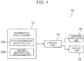
- FIG. 1 is a block diagram illustrating a functional configuration of an attention attracting device 10 for a vehicle according to the present embodiment
- FIG. 2 is a block diagram illustrating one example of a schematic configuration of the attention attracting device 10 for a vehicle.
- FIG. 4 is a schematic plan view illustrating one example of a vehicle 100 mounted with the attention attracting device 10 for a vehicle.
- an arrow FR represents a front side of the vehicle
- an arrow W represents a vehicle width direction.
- the attention attracting device 10 for a vehicle illustrated in FIGS. 1 and 2 is a device mounted on a vehicle to provide various attention attracting information at the time of traveling of the vehicle. As illustrated in FIG. 1 , the attention attracting device 10 for a vehicle is configured to include an information detection unit 12, a control unit 14, a vibration application unit 16, and a display unit 18.
- the information detection unit 12 is a functional unit that detects a plurality of types of attention information around a host vehicle (vehicle mounted with the attention attracting device 10 for a vehicle in the present embodiment).
- the information detection unit 12 is configured to include a first information detection unit 12A and a second information detection unit 12B in the present embodiment.
- a plurality of types of attention information may refer to a plurality of types of attention information different in perspective.
- the term "attention information” may refer to the information that preferably attracts attention of a sitting occupant, when the information is detected.
- the first information detection unit 12A is a functional unit that detects attention information about an obstacle in the vicinity of a front bumper and a rear bumper when the host vehicle travels at low speeds (vehicle speeds of about 10 km/h or less in one example) with use of clearance sonar sensors 22A, 22B, 22C, 22D, 22E, 22F (hereinafter referred to as “clearance sonar sensors 22A to 22F" for short) and a clearance sonar ECU (hereinafter also referred to as "clearance sonar sensor ECU”) 24 illustrated in FIG. 2 .
- a component unit composed of the clearance sonar sensors 22A to 22F and the clearance sonar ECU 24 to function as the first information detection unit 12A (see FIG. 1 ) is referred to as a clearance sonar detection mechanism 20.
- the clearance sonar sensor 22A is attached to a right corner portion of the front bumper 26 of the vehicle 100.
- the clearance sonar sensor 22B is attached to a center portion of the front bumper 26 in a vehicle width direction.
- the clearance sonar sensor 22C is attached to a left corner portion of the front bumper 26.
- the clearance sonar sensor 22D is attached to a right corner portion of the rear bumper 28 of the vehicle 100.
- the clearance sonar sensor 22E is attached to a center portion of the rear bumper 28 in the vehicle width direction.
- the clearance sonar sensor 22F is attached to a left corner portion of the rear bumper 28.
- the clearance sonar sensors 22A to 22F are ultrasonic sensors that transmit ultrasonic waves to detect an obstacle. As illustrated in FIG.
- the clearance sonar sensors 22A to 22F are connected to the clearance sonar ECU 24 to output a detection signal to the clearance sonar ECU 24.
- the clearance sonar ECU 24 includes a CPU, a RAM, a ROM, and an input-output interface unit (input-output).
- the ROM stores a determination control program.
- the clearance sonar ECU 24 determines the position of an obstacle and the distance to the obstacle based on the detection signal from the clearance sonar sensors 22A to 22F.
- the clearance sonar ECU 24 is also connected to a controller 70 through a control area network (CAN) to output a signal relating to the attention information to the controller 70.
- CAN control area network
- the second information detection unit 12B illustrated in FIG. 1 is a functional unit that detects attention information about a lane departure with a camera 32 and a lane departure alert (LDA)-ECU 34 illustrated in FIG. 2 .
- LDA lane departure alert
- a component unit composed of the camera 32 and the LDA-ECU 34 to function as the second information detection unit 12B (see FIG. 1 ) is referred to as a lane departure alert detection mechanism 30.
- the lane departure alert detection mechanism 30 is hereinafter referred to as "LDA detection mechanism 30" for short.
- the camera 32 is a camera including an image sensor, such as a charge-coupled device (CCD), attached to a portion of a windshield glass 36 that is a center portion in the vehicle width direction and that is also an upper portion of the windshield glass 36.
- the camera 32 has an imaging region that is an oblique lower side in front of the host vehicle 100. In one example, the camera 32 is set to repeatedly take an image every several milliseconds.
- the camera 32 is connected to the LDA-ECU 34 to output an image signal to the LDA-ECU 34.
- the LDA-ECU 34 includes a CPU, a RAM, a ROM, and an input-output interface unit (input-output).
- the ROM stores a determination control program.
- the LDA-ECU 34 recognizes a road dividing line in an image imaged with the camera 32, obtains a positional relationship between the host vehicle and a lane, and determines a lane departure or a lane departure possibility of the host vehicle.
- the LDA-ECU 34 is also connected to the controller 70 through the CAN to output a signal relating to attention information to the controller 70.
- a plurality of types of attention information detected by the information detection unit 12 illustrated in FIG. 1 includes both the attention information detected with the clearance sonar detection mechanism 20 illustrated in FIG. 2 (information on an obstacle around the host vehicle detected by using ultrasonic waves) and the attention information detected with the LDA detection mechanism 30 (information indicative of a lane departure or a lane departure possibility of the host vehicle).
- the information detection unit 12 is connected to the control unit 14.
- the control unit 14 will be described later.
- the control unit 14 is connected to the vibration application unit 16 and the display unit 18.
- the vibration application unit 16 is a functional unit configured to include an amplifier 44 and vibrators 46A, 46B, 46C, 46D (hereinafter referred to as "vibrators 46A to 46D" for short) illustrated in FIG. 2 so as to allow application of vibration to a vehicular seat 50 (see FIGS. 4 and 5 ).
- the vehicular seat 50 includes a seat cushion 52 for supporting the buttock and the thigh of an occupant, and the upper surface of the seat cushion 52 is a seat surface 52A on which the occupant sits.
- the seat cushion 52 is slidable in a sheet front-rear direction with a sliding mechanism 58.
- a seatback 54 for supporting the back of the sitting occupant is placed to constitute a sheet rear portion.
- a front surface of the seatback 54 constitutes a backrest surface 54A.
- a headrest 56 is provided for supporting the head of the sitting occupant.
- the vibrator 46A is placed inside the seat cushion 52 at a location that is a front end portion on a right side, and the vibrator 46B is placed inside the seat cushion 52 at a location that is a front end portion on a left side.
- the vibrators 46A, 46B are placed relatively close to the seat surface 52A in the seat cushion 52.
- the vibrator 46C is placed inside the seatback 54 at a location that is an upper end portion on the right side, and the vibrator 46D is placed inside the seatback 54 at a location that is an upper end portion on the left side.
- the vibrators 46C, 46D are placed relatively close to the backrest surface 54A in the seatback 54.
- the vibration application unit 16 see FIG.
- the vibrators 46A to 46D are configured to include motors in one example.
- the vibration control ECU 42 is connected to the vibrators 46A to 46D through the amplifier 44 to control vibration of the vibrators 46A to 46D.
- the vibration control ECU 42 includes a CPU 42A, a RAM 42B, a ROM 42C, and an input-output interface unit (input-output) 42D, which are connected with one another through a bus 42E.
- the ROM 42C is a nonvolatile storage unit, and a vibration control program 43 is stored in the ROM 42C.
- the input-output 42D communicates with component members such as the controller 70 (see FIG. 2 ) connected to the vibration control ECU 42.
- the vibration control ECU 42 controls vibration of the vibrators 46A to 46D illustrated in FIG. 2 when the vibration control program 43 is read from the ROM 42C and transmitted to the RAM 42B, and the vibration control program 43 transmitted to the RAM 42B is executed by the CPU 42A.
- the vibration control ECU 42 is connected to the controller 70 through the CAN to receive a signal relating to attention information from the controller 70.
- the display unit 18 illustrated in FIG. 1 is a functional unit that can display the content of a plurality of types of attention information.
- the content of the attention information is displayed with a meter display device 64 illustrated in FIG. 6 , for example.
- the display unit 18 may be a functional unit that can display the content of a plurality of types of attention information with a center display 66 or a head-up display 68 (hereinafter referred to as "HUD 68") in place of the meter display device 64.
- the meter display device 64 and the center display 66 are placed in an instrument panel 38 of a cabin front 60.
- the HUD 68 has a body portion incorporated in the instrument panel 38 of the host vehicle and performs projection display onto a windshield glass 36. Since the basic configuration of the HUD 68 is publicly known, as disclosed in Japanese Patent Application Publication No. 2017-144889 for example, the detailed description thereof is omitted.
- the meter display device 64 is connected to the controller 70 through a display control ECU 62.
- the center displays 66 may be configured to be connected to the controller 70 through a display control ECU 65
- the HUD 68 may be configured to be connected to the controller 70 through a display control ECU 67.
- the display control ECU 65 and the display control ECU 67 are component units substantially identical to the display control ECU 62.
- the display control ECU 62 includes a CPU 62A, a RAM 62B, a ROM 62C, and an input-output interface unit (input-output) 62D, which are connected with one another through a bus 62E.
- the ROM 62C is a nonvolatile storage unit, and a display control program 63 is stored in the ROM 62C.
- the input-output 62D communicates with component members such as the controller 70 (see FIG. 2 ) connected to the display control ECU 62.
- the display control ECU 62 controls display of the meter display device 64 illustrated in FIG.
- the display control ECU 62 is connected to the controller 70 through the CAN to receive a signal relating to attention information from the controller 70.
- the control unit 14 illustrated in FIG. 1 is a functional unit including the controller 70, the vibration control ECU 42, and the display control ECU 62 illustrated in FIG. 2 .
- the control unit 14 operates the vibration application unit 16 with the controller 70, the vibration control ECU 42, and the display control ECU 62, and displays on the display unit 18 the content corresponding to the detected attention information.
- the control unit 14 operates the vibration application unit 16 with the controller 70, the vibration control ECU 42, and the display control ECU 62, and displays on the display unit 18 the content corresponding to the detected attention information.
- the control unit 14 controls operation of the vibration application unit 16 illustrated in FIG. 1 such that the vibration application unit 16 applies vibration to a region on the side corresponding to any one sides of the right and left front portions to be vibrated 52R, 52L, and the right and left rear portions to be vibrated 54R and 54L as seen in a plan view of the vehicle.
- the control unit 14 controls operation of the vibration application unit 16 such that the vibration application unit 16 applies vibration to both the right and left front portions to be vibrated 52R, 52L (see FIG. 5 ).
- the control unit 14 controls operation of the vibration application unit 16 such that the vibration application unit 16 applies vibration to both the right and left rear portions to be vibrated 54R, 54L (see FIG. 5 ).
- FIGS. 8A to 8F illustrate a relation between the attention information detected with the clearance sonar detection mechanism 20 (see FIG. 2 ) and vibration positions.
- FIGS. 9A and 9B illustrate a relation between the attention information detected with the LDA detection mechanism 30 (see FIG. 2 ) and the vibration positions.
- the host vehicle and the surrounding condition of the host vehicle are illustrated on the right-hand side, and the vibration position of the vehicular seat 50 is illustrated on the left-hand side of the drawings.
- a portion generally corresponding to the region to be vibrated in the vehicular seat 50 is surrounded with a thick circle for easy understanding.
- the vibration control ECU 42 (see FIG. 2 , hereinafter description of reference drawings may properly be omitted) vibrates the vibrator 46C on the right rear side of the vehicular seat 50.
- the vibration control ECU 42 vibrates the vibrator 46D on the left rear side of the vehicular seat 50.
- FIG. 8A when the clearance sonar sensor 22D detects an obstacle 102 on the right rear side of the host vehicle 100, the vibration control ECU 42 (see FIG. 2 , hereinafter description of reference drawings may properly be omitted) vibrates the vibrator 46C on the right rear side of the vehicular seat 50.
- the vibration control ECU 42 vibrates the vibrator 46D on the left rear side of the vehicular seat 50.
- the vibration control ECU 42 vibrates the vibrator 46C on the right rear side of the vehicular seat 50, and the vibrator 46D on the left rear side of the vehicular seat 50.
- the vibration control ECU 42 vibrates the vibrator 46A on the right front side of the vehicular seat 50.
- the vibration control ECU 42 vibrates the vibrator 46B on the left front side of the vehicular seat 50.
- the vibration control ECU 42 vibrates the vibrator 46A on the right front side of the vehicular seat 50, and the vibrator 46B on the left front side of the vehicular seat 50.
- the vibration control ECU 42 vibrates the vibrator 46B on the left front side of the vehicular seat 50.
- the vibration control ECU 42 vibrates the vibrator 46B on the left front side of the vehicular seat 50.
- FIGS. 10A to 10F illustrate display examples in the case of detecting attention information with the clearance sonar detection mechanism 20 (see FIG. 2 ).
- FIGS. 11A and 11B illustrate display examples in the case of detecting attention information with the LDA detection mechanism 30 (see FIG. 2 ).
- FIG. 10A is a display example when an obstacle is detected on the right rear side of the host vehicle.
- a mark M1 representing the presence of an obstacle is displayed on the right rear side of a mark 100A of the host vehicle.
- FIG. 10B is a display example when an obstacle is detected on the left rear side of the host vehicle.
- a mark M2 representing the presence of an obstacle is displayed on the left rear side of the mark 100A of the host vehicle.
- FIG. 10C is a display example when an obstacle is detected right behind the host vehicle.
- a mark M3 representing the presence of an obstacle is displayed right behind the mark 100A of the host vehicle.
- FIG. 10D is a display example when an obstacle is detected on the right front side of the host vehicle.
- a mark M4 representing the presence of an obstacle is displayed on the right front side of the mark 100A of the host vehicle.
- FIG. 10E is a display example when an obstacle is detected on the left front side of the host vehicle.
- a mark M5 representing the presence of an obstacle is displayed on the left front side of the mark 100A of the host vehicle.
- FIG. 10F is a display example when an obstacle is detected right in front of the host vehicle.
- a mark M6 representing the presence of an obstacle is displayed right in front of the mark 100A of the host vehicle.
- the marks M1 to M6 that represent the presence of an obstacle are displayed around the mark 100A of the host vehicle in accordance with the position of the detected obstacle.
- FIG. 11A is a display example in the case of a lane departure or a high possibility of the lane departure of the host vehicle to the left. In this case, a left-side line LL of a travel lane is emphasized.
- FIG. 11B is a display example in the case of a lane departure or a high possibility of the lane departure of the host vehicle to the right. In this case, a right-side line RL is emphasized.
- the meter display device 64 (see FIG. 6 ) emphasizes the line from which the host vehicle departs or possibly departs.
- FIG. 7A A description is now given of the vibration control process executed by the vibration control ECU 42 in the vehicle mounted with the attention attracting device 10 for a vehicle illustrated in FIG. 2 , with reference to a flowchart illustrated in FIG. 7A .
- execution of the display control process illustrated in FIG. 7A is started in one example.
- step 200 of the vibration control process illustrated in FIG. 7A the vibration control ECU 42 determines whether or not attention information is acquired, in other words, whether or not a detection signal of attention information is input from the controller 70.
- the process shifts to step 202.
- the process shifts to step 204.
- step 202 the vibration control ECU 42 controls the vibrators 46A to 46D to vibrate the vehicular seat 50 in accordance with the acquired attention information.
- the relation between the attention information and the vibration regions is as described before (see FIGS. 8A to 8F , 9A and 9B ).
- step 204 the vibration control ECU 42 determines whether or not the ignition switch (IG) of the host vehicle is turned off. When negative determination is made in step 204, the process returns to step 200, and steps 200 to 204 are repeated until positive determination is made in step 204. When positive determination is made in step 204, the vibration control ECU 42 ends the vibration control process illustrated in FIG. 7A .
- IG ignition switch
- step 210 of the display control process illustrated in FIG. 7B the display control ECU 62 determines whether or not attention information is acquired, in other words, whether or not a detection signal of attention information is input from the controller 70.
- the process shifts to step 212.
- the process shifts to step 214.
- step 212 the display control ECU 62 controls operation of the meter display device 64 such that the meter display device 64 displays the content corresponding to the acquired attention information.
- the relation between the attention information and the display examples is as described before (see FIGS. 10A to 10F , 11A and 11B ).
- step 214 the display control ECU 62 determines whether or not the ignition switch (IG) of the host vehicle is turned off. When negative determination is made in step 214, the process returns to step 210, and steps 210 to 214 are repeated until positive determination is made in step 214. When positive determination is made in step 214, the display control ECU 62 ends the display control process illustrated in FIG. 7B .
- IG ignition switch
- the clearance sonar detection mechanism 20 illustrated in FIG. 2 detects attention information in any one region in the vicinity of the front bumper and the rear bumper
- the detected attention information is transmitted to the vibration control ECU 42 and the display control ECU 62 via the controller 70.
- the vibration control ECU 42 controls operation of the vibrators 46A to 46D so as to vibrate a region corresponding to the detection position of the attention information as illustrated in FIGS. 8A to 8F .
- the display control ECU 62 illustrated in FIG. 2 displays the content corresponding to the attention information (one of FIGS. 10A to 10F ) on a display screen of the meter display device 64.
- the attention information is transmitted to the vibration control ECU 42 and the display control ECU 62 via the controller 70.
- the vibration control ECU 42 controls operation of the vibrators 46A to 46D so as to vibrate a region corresponding to the detection position of the attention information as illustrated in FIGS. 9A and 9B .
- the display control ECU 62 illustrated in FIG. 2 displays the content corresponding to the attention information (one of FIGS. 11A and 11B ) on the screen of the meter display device 64.
- a plurality of types of attention information can be transmitted through vibration of the vehicular seat 50 (see FIG. 5 ), and a sitting occupant can easily understand, by viewing the screen of the meter display device 64, the meaning and the content of the attention attracting information transmitted through vibration of the vehicular seat 50.
- the vibrators 46A to 46D can apply vibration to the regions including the right and left front portions to be vibrated 52R, 52L and the right and left rear portions to be vibrated 54R, 54L.
- the right and left front portions to be vibrated 52R, 52L and the right and left rear portions to be vibrated 54R, 54L are provided in both the ends of the vehicular seat 50 in the sheet front-rear direction as seen in a vehicle plan view.
- the control unit 14 illustrated in FIG. 1 controls operation of the vibration application unit 16 such that the vibration application unit 16 illustrated in FIG. 1 applies vibration to a region on the side corresponding to any one sides of the right and left front portions to be vibrated 52R, 52L, and the right and left rear portions to be vibrated 54R, 54L as seen in a plan view of the vehicle.
- the control unit 14 controls operation of the vibration application unit 16 such that the vibration application unit 16 applies vibration to both the right and left front portions to be vibrated 52R, 52L (see FIG. 5 ).
- the control unit 14 controls operation of the vibration application unit 16 such that the vibration application unit 16 applies vibration to both the right and left rear portions to be vibrated 54R, 54L (see FIG. 5 ). Therefore, with the vibration position on the vehicular seat 50, the sitting occupant can easily grasp the detection position of the attention information around the host vehicle as a physical feeling.
- the attention attracting device 10 for a vehicle provides attention information that attracts attention, including the attention information detected with the clearance sonar detection mechanism 20 illustrated in FIG. 2 (information on an obstacle around the host vehicle detected by using ultrasonic waves) and the attention information detected with the LDA detection mechanism 30 (information indicative of a lane departure or a lane departure possibility of the host vehicle).
- the attention information includes high-priority attention information to which the sitting occupant needs to pay special attention. Therefore, safety can be enhanced.
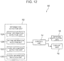
- FIG. 12 is a block diagram illustrating a functional configuration of an attention attracting device 80 for a vehicle according to the present embodiment
- FIG. 13 is a block diagram illustrating one example of a schematic configuration of the attention attracting device 80 for a vehicle.
- FIG. 14 is a schematic plan view illustrating one example of the vehicle 100 mounted with the attention attracting device 80 for a vehicle.
- the present embodiment is substantially identical in configuration to the first embodiment except for the point described below. Accordingly, component units substantially identical to those of the first embodiment are designated by the same reference signs to omit the description thereof.
- the vehicle 100 illustrated in FIG. 14 is different from the vehicle 100 (see FIG.
- the vehicle of the present embodiment is designated by the same reference sign as the vehicle 100 of the first embodiment for the sake of convenience.
- An information detection unit 82 illustrated to FIG. 12 is a functional unit that detects a plurality of types of attention information around the host vehicle.
- the information detection unit 82 includes, in addition to the first information detection unit 12A and the second information detection unit 12B, a third information detection unit 12C and a fourth information detection unit 12D.
- the third information detection unit 12C is a functional unit that detects attention information at the time of lane change and reverse traveling with use of BSM sensors 86A, 86B and BSM-ECUs 88A, 88B illustrated in FIG. 13 .
- a component unit composed of the BSM sensors 86A, 86B and the BSM-ECUs 88A, 88B to function as the third information detection unit 12C (see FIG. 12 ) is referred to as a blind spot monitor-rear cross traffic alert detection mechanism 84.
- the blind spot monitor-rear cross traffic alert detection mechanism 84 is hereinafter referred to as "BSM-RCTA detection mechanism 84" for short.
- the BSM sensor 86A is attached to a wheel house rear end part of a vehicle right-side portion, and the BSM sensor 86B is attached to a wheel house rear end part of a vehicle left-side portion.
- the BSM sensors 86A, 86B are radar sensors that transmit radar waves to detect other vehicles in one example.
- the BSM sensors 86A is connected to the BSM-ECU 88A to output a detection signal to the BSM-ECU 88A.
- the BSM sensor 86B is connected to the BSM-ECU 88B to output a detection signal to the BSM-ECU 88B.
- the BSM-ECUs 88A, 88B each include a CPU, a RAM, a ROM, and an input-output interface unit (input-output).
- the ROM stores a determination control program.
- the BSM-ECUs 88A, 88B determine, at the time of a lane change of the host vehicle, whether or not another vehicle is present on an oblique rear side (in a target lane) that is a dead angle of a rear visual recognition mirror, based on the detection signals from the BSM sensors 86A, 86B.
- the BSM-ECUs 88A, 88B determine whether or not there is another vehicle that is approaching so as to cross the rear side of the host vehicle.
- the BSM-ECUs 88A, 88B are also connected to the controller 70 through the CAN to output signals relating to attention information to the controller 70.
- the fourth information detection unit 12D illustrated in FIG. 12 is a functional unit composed of FCTA sensors 92A, 92B and FCTA-ECUs 94A, 94B illustrated in FIG. 13 to detect attention information at the time of entering an intersection of poor visibility or the like.
- a component unit composed of the FCTA sensors 92A, 92B and the FCTA-ECUs 94A, 94B to function as the fourth information detection unit 12D (see FIG. 12 ) is referred to as a front cross traffic alert detection mechanism 90.
- the front cross traffic alert detection mechanism 90 is hereinafter referred to as "FCTA detection mechanism 90" for short.
- the FCTA sensor 92A is attached to a wheel house front end part of the vehicle right-side portion, and the FCTA sensor 92B is attached to a wheel house front end part of the vehicle left-side portion.
- the FCTA sensors 92A, 92B are radar sensors that transmit radar waves to detect another vehicle in one example.
- the FCTA sensors 92A is connected to the FCTA-ECU 94A to output a detection signal to the FCTA-ECU 94A.
- the FCTA sensor 92B is connected to the FCTA-ECU 94B to output a detection signal to the FCTA-ECU 94B.
- the FCTA-ECUs 94A, 94B each include a CPU, a RAM, a ROM, and an input-output interface unit (input-output).
- the ROM stores a determination control program.
- the FCTA-ECUs 94A, 94B determine, based on the detection signals from the FCTA sensors 92A, 92B, whether or not there is another vehicle that is approaching so as to cross the front side of the host vehicle when the host vehicle enters an intersection of poor visibility or the like.
- the FCTA-ECUs 94A, 94B are also connected to the controller 70 through the CAN to output signals relating to attention information to the controller 70.
- the vibration control ECU 42 illustrated in FIG. 13 is different from the vibration control ECU 42 (see FIG. 2 ) of the first embodiment in that the executed vibration control program is a program for the present embodiment.
- the configuration of the vibration control ECU 42 illustrated in FIG. 13 is similar in other points to that of the vibration control ECU 42 of the first embodiment. Accordingly, the vibration control ECU 42 of the present embodiment is designated by the same reference sign as the vibration control ECU 42 of the first embodiment for the sake of convenience.
- the display control ECU 62 is different from the display control ECU 62 (see FIG. 2 ) of the first embodiment in that the executed display control program is a program for the present embodiment.
- the configuration of the display control ECU 62 is similar in other points to that of the display control ECU 62 of the first embodiment. Accordingly, the display control ECU 62 of the present invention is designated by the same reference sign as the display control ECU 62 of the first embodiment for the sake of convenience.
- FIGS. 15A , 15B , and 16 illustrate a relation between the attention information detected with the BSM-RCTA detection mechanism 84 (see FIG. 13 ) and vibration positions.
- FIG. 17 illustrates a relation between the attention information detected with the FCTA detection mechanism 90 (see FIG. 13 ) and the vibration positions.
- the host vehicle and the surrounding condition of the host vehicle are illustrated on the right-hand side, and the vibration position of the vehicular seat 50 is illustrated on the left-hand side of the drawings.
- a portion generally corresponding to the region to be vibrated in the vehicular seat 50 is surrounded with a thick circle for easy understanding.
- the vibration control ECU 42 (see FIG. 13 , hereinafter description of reference drawings may properly be omitted) vibrates the vibrator 46D on the left rear side of the vehicular seat 50. As illustrated in FIG. 15A , when the host vehicle 100 attempts to make a lane change to the left (see an arrow A) and at that time, the BSM sensor 86B detects another vehicle 106 on the left-hand side of the host vehicle 100, the vibration control ECU 42 (see FIG. 13 , hereinafter description of reference drawings may properly be omitted) vibrates the vibrator 46D on the left rear side of the vehicular seat 50. As illustrated in FIG.
- the BSM sensor 86B detects another vehicle 106 approaching the left rear side of the host vehicle 100 (i.e., traveling in an arrow X1 direction), the vibration control ECU 42 vibrates the vibrator 46D on the left rear side of the vehicular seat 50.
- the BSM sensor 86A detects another vehicle approaching the right rear side of the host vehicle 100, the vibration control ECU 42 vibrates the vibrator 46C on the right rear side of the vehicular seat 50.
- the FCTA sensor 92B detects another vehicle 106 approaching the left front side of the host vehicle 100 (i.e., traveling in an arrow X2 direction), the vibration control ECU 42 vibrates the vibrator 46B on the left front side of the vehicular seat 50.
- the FCTA sensor 92A detects another vehicle approaching the right front side of the host vehicle 100, the vibration control ECU 42 vibrates the vibrator 46A on the right front side of the vehicular seat 50.
- FIGS. 18A to 20 A description of display examples of the attention information displayed on the meter display device 64 (see FIG. 6 ) is now given with reference to FIGS. 18A to 20 .
- FIGS. 18A , 18B , and 19 illustrate display examples in the case of detecting attention information with the BSM-RCTA detection mechanism 84 (see FIG. 13 ).
- FIG. 20 illustrates a display example in the case of detecting attention information with the FCTA detection mechanism 90 (see FIG. 13 ).
- FIG. 18A is a display example when the host vehicle attempts to make a lane change to the left and at that time, another vehicle is detected on the left rear side of the host vehicle. In this case, a mark M7 representing the presence of another vehicle is displayed on the left rear side of the mark 100A of the host vehicle.
- FIG. 18B is a display example when the host vehicle attempts to make a lane change to the right and at that time, another vehicle is detected on the right rear side of the host vehicle. In this case, a mark M8 representing the presence of another vehicle is displayed on the right rear side of the mark 100A of the host vehicle.
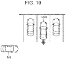
- FIG. 19 is a display example when the host vehicle starts to travel from a parking position in the reverse travel mode and at that time, another vehicle approaching the left rear side of the host vehicle is detected. In this case, a mark M9 or the like representing the presence of another vehicle approaching is displayed. Although not illustrated, a right and left reversed image of FIG. 19 is displayed when the host vehicle starts to travel from a parking position in the reverse travel mode and at that time, another vehicle approaching the right rear side of the host vehicle is detected.
- FIG. 20 is a display example when the host vehicle attempts to enter an intersection of poor visibility or the like and at that time, another vehicle approaching the left front side of the host vehicle is detected.
- a mark M10 representing the presence of another vehicle is displayed on the left front side of the mark 100A of the host vehicle.
- a right and left reversed image of FIG. 20 is displayed when the host vehicle attempts to enter an intersection of poor visibility or the like and at that time, another vehicle approaching the right front side of the host vehicle is detected.
- the flow of the vibration control process executed by the vibration control ECU 42 illustrated in FIG. 13 is similar to the flow illustrated in FIG. 7A
- the flow of the display control process executed by the display control ECU 62 is similar to the flow illustrated in FIG. 7B .
- the effects when the clearance sonar detection mechanism 20 illustrated in FIG. 13 detects attention information in any one region in the vicinity of the front bumper and the rear bumper, and the effects when the LDA detection mechanism 30 detects attention information about a lane departure are similar to those of the first embodiment.
- the attention information is transmitted to the vibration control ECU 42 and the display control ECU 62 via the controller 70.
- the vibration control ECU 42 controls operation of the vibrators 46A to 46D so as to vibrate a region corresponding to the detection position of the attention information as illustrated in FIGS. 15A and 15B .
- the display control ECU 62 illustrated in FIG. 13 displays the content corresponding to the attention information (one of FIGS. 18A and 18B ) on the screen of the meter display device 64.
- the attention information is transmitted to the vibration control ECU 42 and the display control ECU 62 via the controller 70.
- the vibration control ECU 42 controls operation of the vibrators 46A to 46D so as to vibrate a region corresponding to the detection position of the attention information as illustrated in FIG. 16 .
- the display control ECU 62 illustrated in FIG. 13 displays the content corresponding to the attention information ( FIG. 19 or a right and left reversed image of FIG. 19 ) on the screen of the meter display device 64.
- the FCTA detection mechanism 90 illustrated in FIG. 13 detects attention information at the time of entering an intersection with poor visibility or the like, the attention information is transmitted to the vibration control ECU 42 and the display control ECU 62 via the controller 70.
- the vibration control ECU 42 controls operation of the vibrators 46A to 46D so as to vibrate a region corresponding to the detection position of the attention information as illustrated in FIG. 17 .
- the display control ECU 62 illustrated in FIG. 13 displays the content corresponding to the attention information ( FIG. 20 or a right and left reversed image of FIG. 20 ) on the screen of the meter display device 64.
- the present embodiment can also transmit a plurality of types of attention information through vibration of the vehicular seat 50 (see FIG. 14 ), and also enables a sitting occupant to easily understand the meaning and the content of the attention attracting information transmitted through vibration of the vehicular seat 50.
- the vibration application unit may be able to apply vibration to one to three regions, or five or more regions of the vehicular seat, for example.
- the vibration application unit (16) may be a component unit capable of applying vibration to regions, such as a front-side intermediate portion between the right and left front portions to be vibrated 52R, 52L, and a rear-side intermediate portion between the right and left rear portions to be vibrated 54R, 54L, in addition to the right and left front portions to be vibrated 52R, 52L, and the right and left rear portions to be vibrated 54R, 54L illustrated in FIG. 5 .
- control unit (14) may be configured to control operation of the vibration application unit (16) such that the vibration application unit (16) applies vibration to the front-side intermediate portion in place of the right and left front portions to be vibrated (52R, 52L) or together with the right and left front portions to be vibrated (52R, 52L).
- control unit (14) may be configured to control operation of the vibration application unit (16) such that the vibration application unit (16) applies vibration to the rear-side intermediate portion in place of the right and left rear portions to be vibrated (54R, 54L) or together with the right and left rear portions to be vibrated (54R, 54L).
- control unit may be configured to control operation of the vibration application unit such that the vibration application unit changes a vibration pattern of vibration applied to the vehicular seat, in accordance with the content of the detected attention information, the vibration pattern including a vibration frequency, a vibration amplitude, a vibration length, the number of repetitions of vibration, and a vibration interval.
- an intermediate portion of the front bumper 26 of the vehicle 100 illustrated in FIG. 4 or other drawings may be configured to have a plurality of clearance sonar sensors attached in a vehicle width direction such that the clearance sonar sensors are provided side by side in the vehicle width direction.
- an intermediate portion of the rear bumper 28 of the vehicle 100 may be configured to have a plurality of clearance sonar sensors attached in a vehicle width direction such that the clearance sonar sensors are provided side by side in the vehicle width direction.
- the attention attracting device may be configured such that one of or both the clearance sonar detection mechanism 20 and the LDA detection mechanism 30 are excluded.
- controller 70 the vibration control ECU 42, and the display control ECU 62 illustrated in FIGS. 2 and 13 may be configured to be integrated.
- the vehicle mounted with the attention attracting devices 10, 80 for a vehicle in the above embodiments may be mounted with a lane keeping assist control system called lane keeping assist (LKA).
- LKA lane keeping assist
Landscapes
- Engineering & Computer Science (AREA)
- Mechanical Engineering (AREA)
- Transportation (AREA)
- Combustion & Propulsion (AREA)
- Chemical & Material Sciences (AREA)
- Human Computer Interaction (AREA)
- Physics & Mathematics (AREA)
- Aviation & Aerospace Engineering (AREA)
- General Physics & Mathematics (AREA)
- Automation & Control Theory (AREA)
- Remote Sensing (AREA)
- Radar, Positioning & Navigation (AREA)
- Mathematical Physics (AREA)
- Traffic Control Systems (AREA)
- Emergency Alarm Devices (AREA)
- Chair Legs, Seat Parts, And Backrests (AREA)
- Seats For Vehicles (AREA)
Abstract
Description
- The present invention relates to an attention attracting device for a vehicle.
- A technique for attracting attention of a vehicle occupant is known (see Japanese Patent Application Publication No.
2016-207097 JP 2016-207097 A JP 2016-207097 A JP 2016-207097 A - However, assume a case where a plurality of types of attention information different in perspective from each other (for example, information on an obstacle around the host vehicle detected using ultrasonic waves and information indicative of a lane departure or a lane departure possibility of the host vehicle) is transmitted to the driver in the prior art. In this case, even when a stimulus is provided in a given region of the seat, the driver may find it hard to understand or may fail to understand the content of the information that attracts attention.
- The present invention provides an attention attracting device for a vehicle configured such that a plurality of types of attention information is transmitted to a sitting occupant with vibration of a vehicular seat, the attention attracting device enabling the sitting occupant to easily understand the meaning or the content of the attention attracting information through vibration.
- An attention attracting device for a vehicle according to a first aspect of the present invention includes: an information detection unit configured to detect a plurality of types of attention information around a host vehicle; a vibration application application unit configured to apply vibration to a vehicular seat; a display unit configured to display an attention information content corresponding to each of the plurality of types of attention information; and a control unit configured to, when the information detection unit detects attention information, operate the vibration application unit and cause the display unit to display the attention information content corresponding to the detected attention information.
- According to the above aspect, the information detection unit detects a plurality of types of attention information about the periphery of the host vehicle. The vibration application unit can apply vibration to the vehicular seat, and the display unit can display the content of the plurality of types of attention information. When the information detection unit detects attention information, the control unit operates the display unit, and displays on the display unit the content corresponding to the detected attention information. Accordingly, when the vehicular seat vibrates, the sitting occupant can easily understand, by viewing the display on the display unit, the meaning and the content of the information that attracts attention through vibration of the vehicular seat.
- In the above aspect, a vibration pattern may set in accordance with the content of the attention information, and the control unit may configured to operate the vibration application unit with the vibration pattern corresponding to the content of the attention information detected by the information detection unit.
- In the above aspect, the vibration application unit may configured to apply vibration to regions of the vehicular seat, the regions including: a right front portion to be vibrated that is a region on a seat surface side and a right front-end side of a seat cushion in the vehicular seat, a left front portion to be vibrated that is a region on the seat surface side and a left front-end side of the seat cushion in the vehicular seat,
a right rear portion to be vibrated that is a region on a backrest surface side and a right upper-end side of a seatback in the vehicular seat, and a left rear portion to be vibrated that is a region on the backrest surface side and a left upper-end side of the seatback in the vehicular seat. The control unit may configured to: when the information detection unit detects the attention information, and a detection position at which the information detection unit detects the attention information for the host vehicle is at least one side of a right front side, a left front side, a right rear side, and a left rear side of the host vehicle, control an operation of the vibration application unit such that the vibration application unit applies vibration to a region on a side corresponding to the detection position as seen in a plan view of the vehicle, the region being among the right front portion to be vibrated, the left front portion to be vibrated, the right rear portion to be vibrated, and the left rear portion to be vibrated; when the detection position is right in front of the host vehicle, control the operation of the vibration application unit such that the vibration application unit applies vibration to both the right front portion to be vibrated and the left front portion to be vibrated; and when the detection position is right behind the host vehicle, control the operation of the vibration application unit such that the vibration application unit applies vibration to both the right rear portion to be vibrated and the left rear portion to be vibrated. - According to the above aspect, the vibration application unit can apply vibration to regions including the right and left front portions to be vibrated and the right and left rear portions to be vibrated. The right and left front portions to be vibrated and the right and left rear portions to be vibrated are provided on both the ends of the vehicular seat in a sheet front-rear direction as seen in a plan view of the vehicle. When the information detection unit detects attention information, and the detection position of the attention information for the host vehicle is any one of a right front side, a left front side, a right rear side, and a left rear side, the control unit controls operation of the vibration application unit such that the vibration application unit applies vibration to a region on a side corresponding to the detection position as seen in a plan view of the vehicle, the region being among the right front portion to be vibrated, the left front portion to be vibrated, the right rear portion to be vibrated, and the left rear portion to be vibrated. When the information detection unit detects attention information, and the detection position of the attention information is right in front of the host vehicle, the control unit controls operation of the vibration application unit such that the vibration application unit applies vibration to both the right and left front portions to be vibrated. When the detection position of the attention information for the host vehicle is right behind the host vehicle, the control unit controls operation of the vibration application unit such that the vibration application unit applies vibration to both the right and left rear portions to be vibrated. Therefore, with the vibration position on the vehicular seat, the sitting occupant can easily grasp the detection position of the attention information around the host vehicle as a physical feeling.
- In the above aspect, the plurality of types of attention information may include at least one of information on an obstacle around the host vehicle detected using ultrasonic waves, and information indicating a lane departure or a lane departure possibility of the host vehicle.
- According to the above aspect, the plurality of types of attention information detected by the information detection unit includes high-priority attention information to which the sitting occupant needs to pay special attention. Therefore, safety can be enhanced.
- As described in the foregoing, the present invention can provide, in the configuration of transmitting a plurality of types of attention information to a sitting occupant with vibration of a vehicular seat, an excellent effect of enabling the occupant to easily understand the meaning or the content of the attention attracting information transmitted through vibration of the vehicular seat.
- Features, advantages, and technical and industrial significance of exemplary embodiments of the invention will be described below with reference to the accompanying drawings, in which like numerals denote like elements, and wherein:
-
FIG. 1 is a functional block diagram illustrating a functional configuration of an attention attracting device for a vehicle according to a first embodiment; -
FIG. 2 is a block diagram illustrating one example of a schematic configuration of the attention attracting device for a vehicle according to the first embodiment; -
FIG. 3A is a block diagram illustrating a schematic configuration of a vibration control ECU; -
FIG. 3B is a block diagram illustrating a schematic configuration of a display control ECU; -
FIG. 4 is a schematic plan view illustrating one example of a vehicle mounted with the attention attracting device for a vehicle according to the first embodiment; -
FIG. 5 is a schematic perspective view illustrating a vehicular seat of the vehicle mounted with the attention attracting device for a vehicle according to the first embodiment; -
FIG. 6 is a schematic perspective view illustrating a cabin front of the vehicle mounted with the attention attracting device for a vehicle according to the first embodiment; -
FIG. 7A is a flowchart illustrating one example of a process flow executed by the vibration control ECU; -
FIG. 7B is a flowchart illustrating one example of a process flow executed by the display control ECU; -
FIG. 8A is a schematic view illustrating one example of a relation between attention information detected with a clearance sonar detection mechanism and a vibration position; -
FIG. 8B is a schematic view illustrating another example of the relation between attention information detected with the clearance sonar detection mechanism and a vibration position; -
FIG. 8C is a schematic view illustrating another example of the relation between attention information detected with the clearance sonar detection mechanism and a vibration position; -
FIG. 8D is a schematic view illustrating another example of the relation between attention information detected with the clearance sonar detection mechanism and a vibration position; -
FIG. 8E is a schematic view illustrating another example of the relation between attention information detected with the clearance sonar detection mechanism and a vibration position; -
FIG. 8F is a schematic view illustrating another example of the relation between attention information detected with the clearance sonar detection mechanism and a vibration position; -
FIG. 9A is a schematic view illustrating a relation between attention information detected with an LDA detection mechanism and a vibration position; -
FIG. 9B is a schematic view illustrating a relation between attention information detected with the LDA detection mechanism and a vibration position; -
FIG. 10A illustrates a display example in the case of detecting attention information with the clearance sonar detection mechanism; -
FIG. 10B illustrates another display example in the case of detecting attention information with the clearance sonar detection mechanism; -
FIG. 10C illustrates another display example in the case of detecting attention information with the clearance sonar detection mechanism; -
FIG. 10D illustrates another display example in the case of detecting attention information with the clearance sonar detection mechanism; -
FIG. 10E illustrates another display example in the case of detecting attention information with the clearance sonar detection mechanism; -
FIG. 10F illustrates another display example in the case of detecting attention information with the clearance sonar detection mechanism; -
FIG. 11A illustrates a display example in the case of detecting attention information with the LDA detection mechanism; -
FIG. 11B illustrates another display example in the case of detecting attention information with the LDA detection mechanism; -
FIG. 12 is a functional block diagram illustrating a functional configuration of an attention attracting device for a vehicle according to a second embodiment; -
FIG. 13 is a block diagram illustrating one example of a schematic configuration of the attention attracting device for a vehicle according to the second embodiment; -
FIG. 14 is a schematic plan view illustrating one example of a vehicle mounted with the attention attracting device for a vehicle according to the second embodiment; -
FIG. 15A is a schematic view illustrating one example of a relation between attention information at the time of a lane change detected with a BSM-RCTA detection mechanism and a vibration position; -
FIG. 15B is a schematic view illustrating another example of the relation between attention information at the time of a lane change detected with the BSM-RCTA detection mechanism and a vibration position; -
FIG. 16 is a schematic view illustrating a relation between attention information at the time of reverse traveling detected with the BSM-RCTA detection mechanism and a vibration position; -
FIG. 17 is a schematic view illustrating a relation between attention information detected with an FCTA detection mechanism and a vibration position; -
FIG. 18A illustrates a display example when attention information at the time of a lane change is detected with the BSM-RCTA detection mechanism; -
FIG. 18B illustrates another display example when attention information at the time of a lane change is detected with the BSM-RCTA detection mechanism; -
FIG. 19 illustrates a display example when attention information at the time of reverse traveling is detected with the BSM-RCTA detection mechanism; and -
FIG. 20 illustrates a display example when attention information is detected with the FCTA detection mechanism. - An attention attracting device for a vehicle according to a first embodiment of the present invention will be described with reference to
FIGS. 1 to 11B .FIG. 1 is a block diagram illustrating a functional configuration of anattention attracting device 10 for a vehicle according to the present embodiment, andFIG. 2 is a block diagram illustrating one example of a schematic configuration of theattention attracting device 10 for a vehicle.FIG. 4 is a schematic plan view illustrating one example of avehicle 100 mounted with theattention attracting device 10 for a vehicle. InFIG. 4 , an arrow FR represents a front side of the vehicle, and an arrow W represents a vehicle width direction. - The
attention attracting device 10 for a vehicle illustrated inFIGS. 1 and2 is a device mounted on a vehicle to provide various attention attracting information at the time of traveling of the vehicle. As illustrated inFIG. 1 , theattention attracting device 10 for a vehicle is configured to include aninformation detection unit 12, acontrol unit 14, avibration application unit 16, and adisplay unit 18. - The
information detection unit 12 is a functional unit that detects a plurality of types of attention information around a host vehicle (vehicle mounted with theattention attracting device 10 for a vehicle in the present embodiment). Theinformation detection unit 12 is configured to include a firstinformation detection unit 12A and a secondinformation detection unit 12B in the present embodiment. Here, the term "a plurality of types of attention information" may refer to a plurality of types of attention information different in perspective. The term "attention information" may refer to the information that preferably attracts attention of a sitting occupant, when the information is detected. - The first
information detection unit 12A is a functional unit that detects attention information about an obstacle in the vicinity of a front bumper and a rear bumper when the host vehicle travels at low speeds (vehicle speeds of about 10 km/h or less in one example) with use ofclearance sonar sensors clearance sonar sensors 22A to 22F" for short) and a clearance sonar ECU (hereinafter also referred to as "clearance sonar sensor ECU") 24 illustrated inFIG. 2 . In the present embodiment, a component unit composed of theclearance sonar sensors 22A to 22F and theclearance sonar ECU 24 to function as the firstinformation detection unit 12A (seeFIG. 1 ) is referred to as a clearancesonar detection mechanism 20. - As illustrated in
FIG. 4 , theclearance sonar sensor 22A is attached to a right corner portion of thefront bumper 26 of thevehicle 100. Theclearance sonar sensor 22B is attached to a center portion of thefront bumper 26 in a vehicle width direction. Theclearance sonar sensor 22C is attached to a left corner portion of thefront bumper 26. Theclearance sonar sensor 22D is attached to a right corner portion of therear bumper 28 of thevehicle 100. Theclearance sonar sensor 22E is attached to a center portion of therear bumper 28 in the vehicle width direction. Theclearance sonar sensor 22F is attached to a left corner portion of therear bumper 28. Theclearance sonar sensors 22A to 22F are ultrasonic sensors that transmit ultrasonic waves to detect an obstacle. As illustrated inFIG. 2 , theclearance sonar sensors 22A to 22F are connected to theclearance sonar ECU 24 to output a detection signal to theclearance sonar ECU 24. Theclearance sonar ECU 24 includes a CPU, a RAM, a ROM, and an input-output interface unit (input-output). The ROM stores a determination control program. Theclearance sonar ECU 24 determines the position of an obstacle and the distance to the obstacle based on the detection signal from theclearance sonar sensors 22A to 22F. Theclearance sonar ECU 24 is also connected to acontroller 70 through a control area network (CAN) to output a signal relating to the attention information to thecontroller 70. - The second
information detection unit 12B illustrated inFIG. 1 is a functional unit that detects attention information about a lane departure with acamera 32 and a lane departure alert (LDA)-ECU 34 illustrated inFIG. 2 . In the present embodiment, a component unit composed of thecamera 32 and the LDA-ECU 34 to function as the secondinformation detection unit 12B (seeFIG. 1 ) is referred to as a lane departurealert detection mechanism 30. The lane departurealert detection mechanism 30 is hereinafter referred to as "LDA detection mechanism 30" for short. - As illustrated in
FIG. 4 , thecamera 32 is a camera including an image sensor, such as a charge-coupled device (CCD), attached to a portion of awindshield glass 36 that is a center portion in the vehicle width direction and that is also an upper portion of thewindshield glass 36. Thecamera 32 has an imaging region that is an oblique lower side in front of thehost vehicle 100. In one example, thecamera 32 is set to repeatedly take an image every several milliseconds. As illustrated inFIG. 2 , thecamera 32 is connected to the LDA-ECU 34 to output an image signal to the LDA-ECU 34. The LDA-ECU 34 includes a CPU, a RAM, a ROM, and an input-output interface unit (input-output). The ROM stores a determination control program. The LDA-ECU 34 recognizes a road dividing line in an image imaged with thecamera 32, obtains a positional relationship between the host vehicle and a lane, and determines a lane departure or a lane departure possibility of the host vehicle. The LDA-ECU 34 is also connected to thecontroller 70 through the CAN to output a signal relating to attention information to thecontroller 70. - As described in the foregoing, in the present embodiment, a plurality of types of attention information detected by the
information detection unit 12 illustrated inFIG. 1 includes both the attention information detected with the clearancesonar detection mechanism 20 illustrated inFIG. 2 (information on an obstacle around the host vehicle detected by using ultrasonic waves) and the attention information detected with the LDA detection mechanism 30 (information indicative of a lane departure or a lane departure possibility of the host vehicle). - As illustrated in
FIG. 1 , theinformation detection unit 12 is connected to thecontrol unit 14. Thecontrol unit 14 will be described later. Thecontrol unit 14 is connected to thevibration application unit 16 and thedisplay unit 18. - The
vibration application unit 16 is a functional unit configured to include anamplifier 44 andvibrators vibrators 46A to 46D" for short) illustrated inFIG. 2 so as to allow application of vibration to a vehicular seat 50 (seeFIGS. 4 and5 ). - As illustrated in
FIG. 5 , thevehicular seat 50 includes aseat cushion 52 for supporting the buttock and the thigh of an occupant, and the upper surface of theseat cushion 52 is aseat surface 52A on which the occupant sits. Theseat cushion 52 is slidable in a sheet front-rear direction with a slidingmechanism 58. On the upper side of a rear end portion of theseat cushion 52, aseatback 54 for supporting the back of the sitting occupant is placed to constitute a sheet rear portion. A front surface of theseatback 54 constitutes abackrest surface 54A. On the upper side of an upper end portion of theseatback 54, aheadrest 56 is provided for supporting the head of the sitting occupant. - The
vibrator 46A is placed inside theseat cushion 52 at a location that is a front end portion on a right side, and thevibrator 46B is placed inside theseat cushion 52 at a location that is a front end portion on a left side. Thevibrators seat surface 52A in theseat cushion 52. Thevibrator 46C is placed inside theseatback 54 at a location that is an upper end portion on the right side, and thevibrator 46D is placed inside theseatback 54 at a location that is an upper end portion on the left side. Thevibrators backrest surface 54A in theseatback 54. In other words, the vibration application unit 16 (seeFIG. 1 ) of the present embodiment can apply vibration to regions of thevehicular seat 50, including a pair of right and left front portions to be vibrated 52R, 52L which are right and left regions on the side of theseat surface 52A and also on the front end side of theseat cushion 52 in thevehicular seat 50, and a pair of right and left rear portions to be vibrated 54R, 54L which are right and left regions on the side of thebackrest surface 54A and also on the upper end side of theseatback 54 in thevehicular seat 50. Thevibrators 46A to 46D are configured to include motors in one example. - As illustrated in
FIG. 2 , thevibration control ECU 42 is connected to thevibrators 46A to 46D through theamplifier 44 to control vibration of thevibrators 46A to 46D. As illustrated inFIG. 3A , thevibration control ECU 42 includes aCPU 42A, aRAM 42B, aROM 42C, and an input-output interface unit (input-output) 42D, which are connected with one another through abus 42E. TheROM 42C is a nonvolatile storage unit, and avibration control program 43 is stored in theROM 42C. The input-output 42D communicates with component members such as the controller 70 (seeFIG. 2 ) connected to thevibration control ECU 42. Thevibration control ECU 42 controls vibration of thevibrators 46A to 46D illustrated inFIG. 2 when thevibration control program 43 is read from theROM 42C and transmitted to theRAM 42B, and thevibration control program 43 transmitted to theRAM 42B is executed by theCPU 42A. Thevibration control ECU 42 is connected to thecontroller 70 through the CAN to receive a signal relating to attention information from thecontroller 70. - The
display unit 18 illustrated inFIG. 1 is a functional unit that can display the content of a plurality of types of attention information. In the present embodiment, the content of the attention information is displayed with ameter display device 64 illustrated inFIG. 6 , for example. As a modification of the present embodiment, the display unit 18 (seeFIG. 1 ) may be a functional unit that can display the content of a plurality of types of attention information with acenter display 66 or a head-up display 68 (hereinafter referred to as "HUD 68") in place of themeter display device 64. Themeter display device 64 and thecenter display 66 are placed in aninstrument panel 38 of acabin front 60. TheHUD 68 has a body portion incorporated in theinstrument panel 38 of the host vehicle and performs projection display onto awindshield glass 36. Since the basic configuration of theHUD 68 is publicly known, as disclosed in Japanese Patent Application Publication No.2017-144889 - As illustrated in
FIG. 2 , themeter display device 64 is connected to thecontroller 70 through adisplay control ECU 62. As a modification of the present embodiment, the center displays 66 may be configured to be connected to thecontroller 70 through adisplay control ECU 65, and theHUD 68 may be configured to be connected to thecontroller 70 through adisplay control ECU 67. Thedisplay control ECU 65 and thedisplay control ECU 67 are component units substantially identical to thedisplay control ECU 62. - As illustrated in
FIG. 3B , thedisplay control ECU 62 includes aCPU 62A, aRAM 62B, aROM 62C, and an input-output interface unit (input-output) 62D, which are connected with one another through abus 62E. TheROM 62C is a nonvolatile storage unit, and adisplay control program 63 is stored in theROM 62C. The input-output 62D communicates with component members such as the controller 70 (seeFIG. 2 ) connected to thedisplay control ECU 62. Thedisplay control ECU 62 controls display of themeter display device 64 illustrated inFIG. 2 when thedisplay control program 63 is read from theROM 62C and expanded in theRAM 62B, and thedisplay control program 63 expanded in theRAM 62B is executed by theCPU 62A. Thedisplay control ECU 62 is connected to thecontroller 70 through the CAN to receive a signal relating to attention information from thecontroller 70. - The
control unit 14 illustrated inFIG. 1 is a functional unit including thecontroller 70, thevibration control ECU 42, and thedisplay control ECU 62 illustrated inFIG. 2 . When theinformation detection unit 12 illustrated inFIG. 1 detects attention information, thecontrol unit 14 operates thevibration application unit 16 with thecontroller 70, thevibration control ECU 42, and thedisplay control ECU 62, and displays on thedisplay unit 18 the content corresponding to the detected attention information. Here, a more detailed description is given of the control on the operation of thevibration application unit 16 by thecontrol unit 14 when theinformation detection unit 12 detects attention information. When theinformation detection unit 12 detects attention information, and a detection position of the attention information for the host vehicle is any one of a right front side, a left front side, a right rear side, and a left rear side of the host vehicle, thecontrol unit 14 controls operation of thevibration application unit 16 illustrated inFIG. 1 such that thevibration application unit 16 applies vibration to a region on the side corresponding to any one sides of the right and left front portions to be vibrated 52R, 52L, and the right and left rear portions to be vibrated 54R and 54L as seen in a plan view of the vehicle. When theinformation detection unit 12 detects attention information, and a detection position of the attention information for the host vehicle is right in front of the host vehicle, thecontrol unit 14 controls operation of thevibration application unit 16 such that thevibration application unit 16 applies vibration to both the right and left front portions to be vibrated 52R, 52L (seeFIG. 5 ). When theinformation detection unit 12 detects attention information, and a detection position of the attention information for the host vehicle is right behind the host vehicle, thecontrol unit 14 controls operation of thevibration application unit 16 such that thevibration application unit 16 applies vibration to both the right and left rear portions to be vibrated 54R, 54L (seeFIG. 5 ). - Here, a relation between the attention information around the host vehicle and application of vibration to the vehicular seat 50 (see
FIGS. 4 and5 ) is described in detail with reference toFIGS. 8A to 8F ,9A and9B .FIGS. 8A to 8F illustrate a relation between the attention information detected with the clearance sonar detection mechanism 20 (seeFIG. 2 ) and vibration positions.FIGS. 9A and 9B illustrate a relation between the attention information detected with the LDA detection mechanism 30 (seeFIG. 2 ) and the vibration positions. In each ofFIGS. 8A to 8F ,9A and 9B , the host vehicle and the surrounding condition of the host vehicle are illustrated on the right-hand side, and the vibration position of thevehicular seat 50 is illustrated on the left-hand side of the drawings. In each of the drawings, a portion generally corresponding to the region to be vibrated in thevehicular seat 50 is surrounded with a thick circle for easy understanding. - As illustrated in
FIG. 8A , when theclearance sonar sensor 22D detects anobstacle 102 on the right rear side of thehost vehicle 100, the vibration control ECU 42 (seeFIG. 2 , hereinafter description of reference drawings may properly be omitted) vibrates thevibrator 46C on the right rear side of thevehicular seat 50. As illustrated inFIG. 8B , when theclearance sonar sensor 22F detects theobstacle 102 on the left rear side of thehost vehicle 100, thevibration control ECU 42 vibrates thevibrator 46D on the left rear side of thevehicular seat 50. As illustrated inFIG. 8C , when theclearance sonar sensor 22E detects theobstacle 104 right behind thehost vehicle 100, thevibration control ECU 42 vibrates thevibrator 46C on the right rear side of thevehicular seat 50, and thevibrator 46D on the left rear side of thevehicular seat 50. - As illustrated in
FIG. 8D , when theclearance sonar sensor 22A detects theobstacle 102 on the right front side of thehost vehicle 100, thevibration control ECU 42 vibrates thevibrator 46A on the right front side of thevehicular seat 50. As illustrated inFIG. 8E , when theclearance sonar sensor 22C detects theobstacle 102 on the left front side of thehost vehicle 100, thevibration control ECU 42 vibrates thevibrator 46B on the left front side of thevehicular seat 50. As illustrated inFIG. 8F , when theclearance sonar sensor 22B detects theobstacle 104 right in front of thehost vehicle 100, thevibration control ECU 42 vibrates thevibrator 46A on the right front side of thevehicular seat 50, and thevibrator 46B on the left front side of thevehicular seat 50. - As illustrated in
FIG. 9A , when a lane departure or a high possibility of the lane departure of thehost vehicle 100 to the left is determined, thevibration control ECU 42 vibrates thevibrator 46B on the left front side of thevehicular seat 50. To be more specific, when thehost vehicle 100 that is traveling forward departs from a travel lane to the left, the lane departure of thehost vehicle 100 starts from the left front side of thehost vehicle 100. Therefore, the left front side of thevehicular seat 50 is vibrated accordingly. That is, the left front side of thevehicular seat 50 is vibrated to enable a sitting occupant to easily understand the content of the attention information. As illustrated inFIG. 9B , when a lane departure or a high possibility of the lane departure of thehost vehicle 100 to the right is determined, thevibration control ECU 42 vibrates thevibrator 46A on the right front side of thevehicular seat 50. To be more specific, when thehost vehicle 100 that is traveling forward departs from the travel lane to the right, the lane departure of thehost vehicle 100 starts from the right front side of thehost vehicle 100. Therefore, the right front side of thevehicular seat 50 is vibrated accordingly. That is, the right front side of thevehicular seat 50 is vibrated to enable a sitting occupant to easily understand the content of the attention information. InFIGS. 9A and 9B , lines al, a2 represent the lines (dividing lines) that define the lane. - A description is now given of display examples of the attention information displayed on the meter display device 64 (see
FIG. 6 ) with reference toFIGS. 10A to 10F ,11A and11B .FIGS. 10A to 10F illustrate display examples in the case of detecting attention information with the clearance sonar detection mechanism 20 (seeFIG. 2 ).FIGS. 11A and 11B illustrate display examples in the case of detecting attention information with the LDA detection mechanism 30 (seeFIG. 2 ). -
FIG. 10A is a display example when an obstacle is detected on the right rear side of the host vehicle. In this case, a mark M1 representing the presence of an obstacle is displayed on the right rear side of amark 100A of the host vehicle.FIG. 10B is a display example when an obstacle is detected on the left rear side of the host vehicle. In this case, a mark M2 representing the presence of an obstacle is displayed on the left rear side of themark 100A of the host vehicle.FIG. 10C is a display example when an obstacle is detected right behind the host vehicle. In this case, a mark M3 representing the presence of an obstacle is displayed right behind themark 100A of the host vehicle. -
FIG. 10D is a display example when an obstacle is detected on the right front side of the host vehicle. In this case, a mark M4 representing the presence of an obstacle is displayed on the right front side of themark 100A of the host vehicle.FIG. 10E is a display example when an obstacle is detected on the left front side of the host vehicle. In this case, a mark M5 representing the presence of an obstacle is displayed on the left front side of themark 100A of the host vehicle.FIG. 10F is a display example when an obstacle is detected right in front of the host vehicle. In this case, a mark M6 representing the presence of an obstacle is displayed right in front of themark 100A of the host vehicle. - More specifically, when attention information is detected with the clearance sonar detection mechanism 20 (see
FIG. 2 ), the marks M1 to M6 that represent the presence of an obstacle are displayed around themark 100A of the host vehicle in accordance with the position of the detected obstacle. -
FIG. 11A is a display example in the case of a lane departure or a high possibility of the lane departure of the host vehicle to the left. In this case, a left-side line LL of a travel lane is emphasized.FIG. 11B is a display example in the case of a lane departure or a high possibility of the lane departure of the host vehicle to the right. In this case, a right-side line RL is emphasized. In short, the meter display device 64 (seeFIG. 6 ) emphasizes the line from which the host vehicle departs or possibly departs. - A description is now given of the vibration control process executed by the
vibration control ECU 42 in the vehicle mounted with theattention attracting device 10 for a vehicle illustrated inFIG. 2 , with reference to a flowchart illustrated inFIG. 7A . In the present embodiment, when an ignition switch is turned on and a signal indicating the ignition switch is turned on is input into thevibration control ECU 42, execution of the display control process illustrated inFIG. 7A is started in one example. - In
step 200 of the vibration control process illustrated inFIG. 7A , thevibration control ECU 42 determines whether or not attention information is acquired, in other words, whether or not a detection signal of attention information is input from thecontroller 70. When positive determination is made instep 200, the process shifts to step 202. When negative determination is made instep 200, the process shifts to step 204. - In
step 202, thevibration control ECU 42 controls thevibrators 46A to 46D to vibrate thevehicular seat 50 in accordance with the acquired attention information. The relation between the attention information and the vibration regions is as described before (seeFIGS. 8A to 8F ,9A and 9B ). - In
subsequent step 204, thevibration control ECU 42 determines whether or not the ignition switch (IG) of the host vehicle is turned off. When negative determination is made instep 204, the process returns to step 200, and steps 200 to 204 are repeated until positive determination is made instep 204. When positive determination is made instep 204, thevibration control ECU 42 ends the vibration control process illustrated inFIG. 7A . - Next, the display control process executed by the
display control ECU 62 in the vehicle mounted with theattention attracting device 10 for a vehicle illustrated inFIG. 2 will be described with reference to a flowchart illustrated inFIG. 7B . In the present embodiment, when the ignition switch is turned on and a signal indicating that the ignition switch is turned on is input into thedisplay control ECU 62, execution of the display control process illustrated inFIG. 7B is started in one example. - In
step 210 of the display control process illustrated inFIG. 7B , thedisplay control ECU 62 determines whether or not attention information is acquired, in other words, whether or not a detection signal of attention information is input from thecontroller 70. When positive determination is made instep 210, the process shifts to step 212. When negative determination is made instep 210, the process shifts to step 214. - In
step 212, thedisplay control ECU 62 controls operation of themeter display device 64 such that themeter display device 64 displays the content corresponding to the acquired attention information. The relation between the attention information and the display examples is as described before (seeFIGS. 10A to 10F ,11A and 11B ). - In
subsequent step 214, thedisplay control ECU 62 determines whether or not the ignition switch (IG) of the host vehicle is turned off. When negative determination is made instep 214, the process returns to step 210, and steps 210 to 214 are repeated until positive determination is made instep 214. When positive determination is made instep 214, thedisplay control ECU 62 ends the display control process illustrated inFIG. 7B . - Next, functions and effects of the present embodiment will be described.
- First, when the clearance
sonar detection mechanism 20 illustrated inFIG. 2 detects attention information in any one region in the vicinity of the front bumper and the rear bumper, the detected attention information is transmitted to thevibration control ECU 42 and thedisplay control ECU 62 via thecontroller 70. Thevibration control ECU 42 controls operation of thevibrators 46A to 46D so as to vibrate a region corresponding to the detection position of the attention information as illustrated inFIGS. 8A to 8F . Thedisplay control ECU 62 illustrated inFIG. 2 displays the content corresponding to the attention information (one ofFIGS. 10A to 10F ) on a display screen of themeter display device 64. - When the
LDA detection mechanism 30 illustrated inFIG. 2 detects attention information about a lane departure, the attention information is transmitted to thevibration control ECU 42 and thedisplay control ECU 62 via thecontroller 70. Thevibration control ECU 42 controls operation of thevibrators 46A to 46D so as to vibrate a region corresponding to the detection position of the attention information as illustrated inFIGS. 9A and 9B . Thedisplay control ECU 62 illustrated inFIG. 2 displays the content corresponding to the attention information (one ofFIGS. 11A and 11B ) on the screen of themeter display device 64. - As described in the foregoing, in the present embodiment, a plurality of types of attention information can be transmitted through vibration of the vehicular seat 50 (see
FIG. 5 ), and a sitting occupant can easily understand, by viewing the screen of themeter display device 64, the meaning and the content of the attention attracting information transmitted through vibration of thevehicular seat 50. - In the present embodiment, in the
vehicular seat 50 illustrated inFIG. 5 , thevibrators 46A to 46D (vibration application unit 16 (seeFIG. 1 )) can apply vibration to the regions including the right and left front portions to be vibrated 52R, 52L and the right and left rear portions to be vibrated 54R, 54L. The right and left front portions to be vibrated 52R, 52L and the right and left rear portions to be vibrated 54R, 54L are provided in both the ends of thevehicular seat 50 in the sheet front-rear direction as seen in a vehicle plan view. When theinformation detection unit 12 detects attention information, and the detection position of the attention information for the host vehicle is any one side of a right front side, a left front side, a right rear side, and a left rear side, thecontrol unit 14 illustrated inFIG. 1 controls operation of thevibration application unit 16 such that thevibration application unit 16 illustrated inFIG. 1 applies vibration to a region on the side corresponding to any one sides of the right and left front portions to be vibrated 52R, 52L, and the right and left rear portions to be vibrated 54R, 54L as seen in a plan view of the vehicle. When theinformation detection unit 12 detects attention information, and the detection position of the attention information for the host vehicle is right in front of the host vehicle, thecontrol unit 14 controls operation of thevibration application unit 16 such that thevibration application unit 16 applies vibration to both the right and left front portions to be vibrated 52R, 52L (seeFIG. 5 ). When the detection position of the attention information for the host vehicle is right behind the host vehicle, thecontrol unit 14 controls operation of thevibration application unit 16 such that thevibration application unit 16 applies vibration to both the right and left rear portions to be vibrated 54R, 54L (seeFIG. 5 ). Therefore, with the vibration position on thevehicular seat 50, the sitting occupant can easily grasp the detection position of the attention information around the host vehicle as a physical feeling. - In the present embodiment, the
attention attracting device 10 for a vehicle provides attention information that attracts attention, including the attention information detected with the clearancesonar detection mechanism 20 illustrated inFIG. 2 (information on an obstacle around the host vehicle detected by using ultrasonic waves) and the attention information detected with the LDA detection mechanism 30 (information indicative of a lane departure or a lane departure possibility of the host vehicle). In other words, the attention information includes high-priority attention information to which the sitting occupant needs to pay special attention. Therefore, safety can be enhanced. - An attention attracting device for a vehicle according to a second embodiment of the present invention will be described with reference to
FIGS. 12 to 20 .FIG. 12 is a block diagram illustrating a functional configuration of anattention attracting device 80 for a vehicle according to the present embodiment, andFIG. 13 is a block diagram illustrating one example of a schematic configuration of theattention attracting device 80 for a vehicle.FIG. 14 is a schematic plan view illustrating one example of thevehicle 100 mounted with theattention attracting device 80 for a vehicle. The present embodiment is substantially identical in configuration to the first embodiment except for the point described below. Accordingly, component units substantially identical to those of the first embodiment are designated by the same reference signs to omit the description thereof. Although thevehicle 100 illustrated inFIG. 14 is different from the vehicle 100 (seeFIG. 4 ) of the first embodiment in that theattention attracting device 10 for a vehicle (seeFIG. 2 or the like) of the first embodiment is replaced with theattention attracting device 80 for a vehicle (seeFIG. 13 or the like), the vehicle of the present embodiment is designated by the same reference sign as thevehicle 100 of the first embodiment for the sake of convenience. - An
information detection unit 82 illustrated toFIG. 12 is a functional unit that detects a plurality of types of attention information around the host vehicle. In the present embodiment, theinformation detection unit 82 includes, in addition to the firstinformation detection unit 12A and the secondinformation detection unit 12B, a thirdinformation detection unit 12C and a fourthinformation detection unit 12D. - The third
information detection unit 12C is a functional unit that detects attention information at the time of lane change and reverse traveling with use ofBSM sensors ECUs FIG. 13 . In the present embodiment, a component unit composed of theBSM sensors ECUs information detection unit 12C (seeFIG. 12 ) is referred to as a blind spot monitor-rear cross trafficalert detection mechanism 84. The blind spot monitor-rear cross trafficalert detection mechanism 84 is hereinafter referred to as "BSM-RCTA detection mechanism 84" for short. - As illustrated in
FIG. 14 , theBSM sensor 86A is attached to a wheel house rear end part of a vehicle right-side portion, and theBSM sensor 86B is attached to a wheel house rear end part of a vehicle left-side portion. TheBSM sensors FIG. 13 , theBSM sensors 86A is connected to the BSM-ECU 88A to output a detection signal to the BSM-ECU 88A. TheBSM sensor 86B is connected to the BSM-ECU 88B to output a detection signal to the BSM-ECU 88B. The BSM-ECUs ECUs BSM sensors ECUs ECUs controller 70 through the CAN to output signals relating to attention information to thecontroller 70. - The fourth
information detection unit 12D illustrated inFIG. 12 is a functional unit composed ofFCTA sensors ECUs FIG. 13 to detect attention information at the time of entering an intersection of poor visibility or the like. In the present embodiment, a component unit composed of theFCTA sensors ECUs information detection unit 12D (seeFIG. 12 ) is referred to as a front cross trafficalert detection mechanism 90. The front cross trafficalert detection mechanism 90 is hereinafter referred to as "FCTA detection mechanism 90" for short. - As illustrated in
FIG. 14 , theFCTA sensor 92A is attached to a wheel house front end part of the vehicle right-side portion, and theFCTA sensor 92B is attached to a wheel house front end part of the vehicle left-side portion. TheFCTA sensors FIG. 13 , theFCTA sensors 92A is connected to the FCTA-ECU 94A to output a detection signal to the FCTA-ECU 94A. TheFCTA sensor 92B is connected to the FCTA-ECU 94B to output a detection signal to the FCTA-ECU 94B. The FCTA-ECUs ECUs FCTA sensors ECUs controller 70 through the CAN to output signals relating to attention information to thecontroller 70. - The
vibration control ECU 42 illustrated inFIG. 13 is different from the vibration control ECU 42 (seeFIG. 2 ) of the first embodiment in that the executed vibration control program is a program for the present embodiment. However, the configuration of thevibration control ECU 42 illustrated inFIG. 13 is similar in other points to that of thevibration control ECU 42 of the first embodiment. Accordingly, thevibration control ECU 42 of the present embodiment is designated by the same reference sign as thevibration control ECU 42 of the first embodiment for the sake of convenience. Thedisplay control ECU 62 is different from the display control ECU 62 (seeFIG. 2 ) of the first embodiment in that the executed display control program is a program for the present embodiment. However, the configuration of thedisplay control ECU 62 is similar in other points to that of thedisplay control ECU 62 of the first embodiment. Accordingly, thedisplay control ECU 62 of the present invention is designated by the same reference sign as thedisplay control ECU 62 of the first embodiment for the sake of convenience. - Here, a relation between the attention information around the host vehicle and application of vibration to the vehicular seat 50 (see
FIGS. 14 and15 ) is described with reference toFIGS. 15A to 17 .FIGS. 15A ,15B , and16 illustrate a relation between the attention information detected with the BSM-RCTA detection mechanism 84 (seeFIG. 13 ) and vibration positions.FIG. 17 illustrates a relation between the attention information detected with the FCTA detection mechanism 90 (seeFIG. 13 ) and the vibration positions. In each ofFIGS. 15A, 15B ,16 , and17 , the host vehicle and the surrounding condition of the host vehicle are illustrated on the right-hand side, and the vibration position of thevehicular seat 50 is illustrated on the left-hand side of the drawings. In each of the drawings, a portion generally corresponding to the region to be vibrated in thevehicular seat 50 is surrounded with a thick circle for easy understanding. - As illustrated in
FIG. 15A , when thehost vehicle 100 attempts to make a lane change to the left (see an arrow A) and at that time, theBSM sensor 86B detects anothervehicle 106 on the left-hand side of thehost vehicle 100, the vibration control ECU 42 (seeFIG. 13 , hereinafter description of reference drawings may properly be omitted) vibrates thevibrator 46D on the left rear side of thevehicular seat 50. As illustrated inFIG. 15B , when thehost vehicle 100 attempts to make a lane change to the right (see an arrow B) and at that time, theBSM sensor 86A detects anothervehicle 106 on the right-hand side of thehost vehicle 100, thevibration control ECU 42 vibrates thevibrator 46C on the right rear side of thevehicular seat 50. - As illustrated in
FIG. 16 , when thehost vehicle 100 attempts to start traveling from a parking position in a reverse travel mode (see an arrow C) and at that time, theBSM sensor 86B detects anothervehicle 106 approaching the left rear side of the host vehicle 100 (i.e., traveling in an arrow X1 direction), thevibration control ECU 42 vibrates thevibrator 46D on the left rear side of thevehicular seat 50. Although not illustrated, when thehost vehicle 100 attempts to start traveling from a parking position in the reverse travel mode and at that time, theBSM sensor 86A detects another vehicle approaching the right rear side of thehost vehicle 100, thevibration control ECU 42 vibrates thevibrator 46C on the right rear side of thevehicular seat 50. - As illustrated in
FIG. 17 , when thehost vehicle 100 attempts to enter an intersection of poor visibility or the like (see an arrow D) and at that time, theFCTA sensor 92B detects anothervehicle 106 approaching the left front side of the host vehicle 100 (i.e., traveling in an arrow X2 direction), thevibration control ECU 42 vibrates thevibrator 46B on the left front side of thevehicular seat 50. Although not illustrated, when thehost vehicle 100 attempts to enter an intersection of poor visibility or the like and at that time, theFCTA sensor 92A detects another vehicle approaching the right front side of thehost vehicle 100, thevibration control ECU 42 vibrates thevibrator 46A on the right front side of thevehicular seat 50. - A description of display examples of the attention information displayed on the meter display device 64 (see
FIG. 6 ) is now given with reference toFIGS. 18A to 20 .FIGS. 18A ,18B , and19 illustrate display examples in the case of detecting attention information with the BSM-RCTA detection mechanism 84 (seeFIG. 13 ).FIG. 20 illustrates a display example in the case of detecting attention information with the FCTA detection mechanism 90 (seeFIG. 13 ). -
FIG. 18A is a display example when the host vehicle attempts to make a lane change to the left and at that time, another vehicle is detected on the left rear side of the host vehicle. In this case, a mark M7 representing the presence of another vehicle is displayed on the left rear side of themark 100A of the host vehicle.FIG. 18B is a display example when the host vehicle attempts to make a lane change to the right and at that time, another vehicle is detected on the right rear side of the host vehicle. In this case, a mark M8 representing the presence of another vehicle is displayed on the right rear side of themark 100A of the host vehicle. -
FIG. 19 is a display example when the host vehicle starts to travel from a parking position in the reverse travel mode and at that time, another vehicle approaching the left rear side of the host vehicle is detected. In this case, a mark M9 or the like representing the presence of another vehicle approaching is displayed. Although not illustrated, a right and left reversed image ofFIG. 19 is displayed when the host vehicle starts to travel from a parking position in the reverse travel mode and at that time, another vehicle approaching the right rear side of the host vehicle is detected. -
FIG. 20 is a display example when the host vehicle attempts to enter an intersection of poor visibility or the like and at that time, another vehicle approaching the left front side of the host vehicle is detected. In this case, a mark M10 representing the presence of another vehicle is displayed on the left front side of themark 100A of the host vehicle. Although not illustrated, a right and left reversed image ofFIG. 20 is displayed when the host vehicle attempts to enter an intersection of poor visibility or the like and at that time, another vehicle approaching the right front side of the host vehicle is detected. - Next, functions and effects of the above embodiment will be described. The flow of the vibration control process executed by the
vibration control ECU 42 illustrated inFIG. 13 is similar to the flow illustrated inFIG. 7A , and the flow of the display control process executed by thedisplay control ECU 62 is similar to the flow illustrated inFIG. 7B . - First, the effects when the clearance
sonar detection mechanism 20 illustrated inFIG. 13 detects attention information in any one region in the vicinity of the front bumper and the rear bumper, and the effects when theLDA detection mechanism 30 detects attention information about a lane departure are similar to those of the first embodiment. - When the BSM-
RCTA detection mechanism 84 illustrated inFIG. 13 detects attention information at the time of a lane change, the attention information is transmitted to thevibration control ECU 42 and thedisplay control ECU 62 via thecontroller 70. Thevibration control ECU 42 controls operation of thevibrators 46A to 46D so as to vibrate a region corresponding to the detection position of the attention information as illustrated inFIGS. 15A and 15B . Thedisplay control ECU 62 illustrated inFIG. 13 displays the content corresponding to the attention information (one ofFIGS. 18A and 18B ) on the screen of themeter display device 64. - When the BSM-
RCTA detection mechanism 84 illustrated inFIG. 13 detects attention information at the time of reverse traveling, the attention information is transmitted to thevibration control ECU 42 and thedisplay control ECU 62 via thecontroller 70. Thevibration control ECU 42 controls operation of thevibrators 46A to 46D so as to vibrate a region corresponding to the detection position of the attention information as illustrated inFIG. 16 . Thedisplay control ECU 62 illustrated inFIG. 13 displays the content corresponding to the attention information (FIG. 19 or a right and left reversed image ofFIG. 19 ) on the screen of themeter display device 64. - When the
FCTA detection mechanism 90 illustrated inFIG. 13 detects attention information at the time of entering an intersection with poor visibility or the like, the attention information is transmitted to thevibration control ECU 42 and thedisplay control ECU 62 via thecontroller 70. Thevibration control ECU 42 controls operation of thevibrators 46A to 46D so as to vibrate a region corresponding to the detection position of the attention information as illustrated inFIG. 17 . Thedisplay control ECU 62 illustrated inFIG. 13 displays the content corresponding to the attention information (FIG. 20 or a right and left reversed image ofFIG. 20 ) on the screen of themeter display device 64. - As described in the foregoing, the present embodiment can also transmit a plurality of types of attention information through vibration of the vehicular seat 50 (see
FIG. 14 ), and also enables a sitting occupant to easily understand the meaning and the content of the attention attracting information transmitted through vibration of thevehicular seat 50. - As a modification of the above embodiment, the vibration application unit may be able to apply vibration to one to three regions, or five or more regions of the vehicular seat, for example. As an example where the vibration application unit can apply vibration to five or more regions of the vehicular seat, the vibration application unit (16) may be a component unit capable of applying vibration to regions, such as a front-side intermediate portion between the right and left front portions to be vibrated 52R, 52L, and a rear-side intermediate portion between the right and left rear portions to be vibrated 54R, 54L, in addition to the right and left front portions to be vibrated 52R, 52L, and the right and left rear portions to be vibrated 54R, 54L illustrated in
FIG. 5 . In this case, when, for example, the clearance sonar sensor (22B) detects an obstacle right in front of the host vehicle (100), the control unit (14) may be configured to control operation of the vibration application unit (16) such that the vibration application unit (16) applies vibration to the front-side intermediate portion in place of the right and left front portions to be vibrated (52R, 52L) or together with the right and left front portions to be vibrated (52R, 52L). When the clearance sonar sensor (22E) detects an obstacle right behind the host vehicle (100), the control unit (14) may be configured to control operation of the vibration application unit (16) such that the vibration application unit (16) applies vibration to the rear-side intermediate portion in place of the right and left rear portions to be vibrated (54R, 54L) or together with the right and left rear portions to be vibrated (54R, 54L). - As a modification of the above embodiment, the control unit may be configured to control operation of the vibration application unit such that the vibration application unit changes a vibration pattern of vibration applied to the vehicular seat, in accordance with the content of the detected attention information, the vibration pattern including a vibration frequency, a vibration amplitude, a vibration length, the number of repetitions of vibration, and a vibration interval.
- As a modification of the above embodiment, an intermediate portion of the
front bumper 26 of thevehicle 100 illustrated inFIG. 4 or other drawings may be configured to have a plurality of clearance sonar sensors attached in a vehicle width direction such that the clearance sonar sensors are provided side by side in the vehicle width direction. Alternatively, an intermediate portion of therear bumper 28 of thevehicle 100 may be configured to have a plurality of clearance sonar sensors attached in a vehicle width direction such that the clearance sonar sensors are provided side by side in the vehicle width direction. - As a modification of the second embodiment, the attention attracting device may be configured such that one of or both the clearance
sonar detection mechanism 20 and theLDA detection mechanism 30 are excluded. - As a modification of the embodiment, the
controller 70, thevibration control ECU 42, and thedisplay control ECU 62 illustrated inFIGS. 2 and13 may be configured to be integrated. - Incidentally, the vehicle mounted with the
attention attracting devices - The above embodiments and the above-described modifications may be implemented in proper combinations.
- Although examples of the present invention have been described, the present invention is not limited to the examples disclosed. It is naturally understood that various changes are possible without departing from the scope of the appended claims.
Claims (4)
- An attention attracting device for a vehicle comprising:an information detection unit (12) configured to detect a plurality of types of attention information around a host vehicle (100);a vibration application unit (16) configured to apply vibration to a vehicular seat (50);a display unit (18) configured to display attention information content corresponding to each of the plurality of types of attention information; anda control unit (14) configured to, when the information detection unit (12) detects attention information,operate the vibration application unit (16) andcause the display unit (18) to display the attention information content corresponding to the detected attention information.
- The attention attracting device according to claim 1, wherein
a vibration pattern is set in accordance with the content of the attention information, and
the control unit (14) is configured to operate the vibration application unit (16) with the vibration pattern corresponding to the content of the attention information detected by the information detection unit (12). - The attention attracting device according to claim 1 or 2, wherein
the vibration application unit (16) is configured to apply vibration to regions of the vehicular seat (50), the regions includea right front portion to be vibrated that is a region on a seat surface side and a right front-end side of a seat cushion in the vehicular seat (50),a left front portion to be vibrated that is a region on the seat surface side and a left front-end side of the seat cushion in the vehicular seat (50),a right rear portion to be vibrated that is a region on a backrest surface side and a right upper-end side of a seatback in the vehicular seat (50), anda left rear portion to be vibrated that is a region on the backrest surface side and a left upper-end side of the seatback in the vehicular seat (50), andthe control unit (14) is configured to:when the information detection unit (12) detects the attention information, and a detection position at which the information detection unit (12) detects the attention information for the host vehicle (100) is at least one side of a right front side, a left front side, a right rear side, and a left rear side of the host vehicle (100), control an operation of the vibration application unit (16) such that the vibration application unit (16) applies vibration to a region on a side corresponding to the detection position as seen in a plan view of the vehicle, the region being among the right front portion to be vibrated, the left front portion to be vibrated, the right rear portion to be vibrated, and the left rear portion to be vibrated;when the detection position is right in front of the host vehicle (100), control the operation of the vibration application unit (16) such that the vibration application unit (16) applies vibration to both the right front portion to be vibrated and the left front portion to be vibrated; andwhen the detection position is right behind the host vehicle (100), control the operation of the vibration application unit (16) such that the vibration application unit (16) applies vibration to both the right rear portion to be vibrated and the left rear portion to be vibrated. - The attention attracting device according to any one of claims 1 to 3, wherein the plurality of types of attention information includes at least one of information on an obstacle around the host vehicle (100) detected using ultrasonic waves, and information indicating a lane departure or a lane departure possibility of the host vehicle (100).
Applications Claiming Priority (1)
| Application Number | Priority Date | Filing Date | Title |
|---|---|---|---|
| JP2017236138A JP6954069B2 (en) | 2017-12-08 | 2017-12-08 | Vehicle alert device |
Publications (2)
| Publication Number | Publication Date |
|---|---|
| EP3495187A1 true EP3495187A1 (en) | 2019-06-12 |
| EP3495187B1 EP3495187B1 (en) | 2022-08-24 |
Family
ID=64277610
Family Applications (1)
| Application Number | Title | Priority Date | Filing Date |
|---|---|---|---|
| EP18205737.2A Not-in-force EP3495187B1 (en) | 2017-12-08 | 2018-11-12 | Attention attracting device for vehicle |
Country Status (7)
| Country | Link |
|---|---|
| US (1) | US10703267B2 (en) |
| EP (1) | EP3495187B1 (en) |
| JP (1) | JP6954069B2 (en) |
| KR (1) | KR20190068414A (en) |
| CN (1) | CN109895789A (en) |
| BR (1) | BR102018072648A2 (en) |
| RU (1) | RU2709702C1 (en) |
Families Citing this family (8)
| Publication number | Priority date | Publication date | Assignee | Title |
|---|---|---|---|---|
| JP7192600B2 (en) * | 2019-03-20 | 2022-12-20 | 株式会社デンソー | alarm device |
| US11231501B2 (en) | 2019-09-26 | 2022-01-25 | Baidu Usa Llc | Front and side three-LIDAR design for autonomous driving vehicles |
| US11705002B2 (en) * | 2019-12-11 | 2023-07-18 | Waymo Llc | Application monologue for self-driving vehicles |
| WO2022168527A1 (en) * | 2021-02-04 | 2022-08-11 | テイ・エス テック株式会社 | Seat device for vehicle |
| CN113734190B (en) * | 2021-09-09 | 2023-04-11 | 北京百度网讯科技有限公司 | Vehicle information prompting method and device, electronic equipment, medium and vehicle |
| CN113706872B (en) * | 2021-09-27 | 2023-04-18 | 陕西汉唐计算机有限责任公司 | Fatigue driving prevention method |
| JP2024034046A (en) | 2022-08-31 | 2024-03-13 | トヨタ自動車株式会社 | Driving support device, driving support method, and driving support program |
| US12589765B2 (en) | 2023-01-10 | 2026-03-31 | Woven By Toyota, Inc. | Systems and methods for enhancing operator vigilance |
Citations (6)
| Publication number | Priority date | Publication date | Assignee | Title |
|---|---|---|---|---|
| JP2000020900A (en) * | 1998-07-03 | 2000-01-21 | Hitachi Ltd | Inter-vehicle distance warning device and centralized wiring device |
| JP2001199296A (en) * | 2000-01-17 | 2001-07-24 | Matsushita Electric Ind Co Ltd | Alarm device, driver's seat with vibrating body, mobile body with alarm device mounted on vehicle |
| US20050258977A1 (en) * | 2004-05-18 | 2005-11-24 | Kiefer Raymond J | Collision avoidance system |
| US20050273263A1 (en) * | 2004-06-02 | 2005-12-08 | Nissan Motor Co., Ltd. | Driving assistance method and system for conveying risk information |
| JP2016207097A (en) | 2015-04-27 | 2016-12-08 | 公立大学法人岩手県立大学 | Situation communication device to driver |
| JP2017144889A (en) | 2016-02-17 | 2017-08-24 | トヨタ自動車株式会社 | In-vehicle device, control method for in-vehicle device, and control program for in-vehicle device |
Family Cites Families (37)
| Publication number | Priority date | Publication date | Assignee | Title |
|---|---|---|---|---|
| US20050259033A1 (en) * | 2004-05-20 | 2005-11-24 | Levine Alfred B | Multiplex-selective heads-up displays for cars |
| JP2006119840A (en) * | 2004-10-20 | 2006-05-11 | Hitachi Ltd | Warning device for vehicle |
| JP4557819B2 (en) * | 2005-06-21 | 2010-10-06 | アルパイン株式会社 | Vehicle periphery information providing device |
| US20070244641A1 (en) * | 2006-04-17 | 2007-10-18 | Gm Global Technology Operations, Inc. | Active material based haptic communication systems |
| JP2008056172A (en) | 2006-09-01 | 2008-03-13 | Toyota Motor Corp | Vehicle alert system |
| EP1998141B1 (en) * | 2007-05-31 | 2015-04-15 | Aisin AW Co., Ltd. | Navigation device, navigation method and navigation program |
| KR100882687B1 (en) | 2007-12-06 | 2009-02-06 | 현대자동차주식회사 | Vehicle rear obstacle warning device and alarm method |
| CN101782646B (en) * | 2009-01-19 | 2012-08-29 | 财团法人工业技术研究院 | Surrounding environment sensing system and method |
| US8629784B2 (en) * | 2009-04-02 | 2014-01-14 | GM Global Technology Operations LLC | Peripheral salient feature enhancement on full-windshield head-up display |
| DE102009046230A1 (en) | 2009-10-30 | 2011-05-12 | Robert Bosch Gmbh | Collision monitoring for a motor vehicle |
| CN201576090U (en) * | 2009-12-03 | 2010-09-08 | 刘宛莲 | Front and back reversing radar warning system |
| CN102656613B (en) | 2009-12-18 | 2015-02-11 | 本田技研工业株式会社 | A predictive human-machine interface using eye gaze technology, blind spot indicators and driver experience |
| CN101833092B (en) * | 2010-04-27 | 2012-07-04 | 成都捌零科技有限公司 | 360-degree dead-angle-free obstacle intelligent detection and early warning method for vehicle |
| JP5338801B2 (en) * | 2010-12-23 | 2013-11-13 | 株式会社デンソー | In-vehicle obstacle information notification device |
| DE102011117297A1 (en) * | 2011-11-01 | 2013-05-02 | Volkswagen Aktiengesellschaft | Method for operating a driver assistance system and associated driver assistance system |
| US9545879B2 (en) * | 2012-06-22 | 2017-01-17 | GM Global Technology Operations LLC | Vehicle seat back haptic alert systems and methods |
| US9286773B2 (en) * | 2012-06-22 | 2016-03-15 | GM Global Technology Operations LLC | Alert systems and methods for a vehicle with improved actuator installation |
| US9266451B2 (en) * | 2012-06-22 | 2016-02-23 | GM Global Technology Operations LLC | Alert systems and methods for a vehicle |
| US9349263B2 (en) * | 2012-06-22 | 2016-05-24 | GM Global Technology Operations LLC | Alert systems and methods for a vehicle |
| US9004589B2 (en) * | 2012-07-03 | 2015-04-14 | Toyota Boshoku America, Inc. | Vibratory alert patch |
| TWM454349U (en) * | 2012-10-29 | 2013-06-01 | Hua Chuang Automobile Information Technical Ct Co Ltd | Omnidirectional alarming system for vehicle |
| DE102012111318A1 (en) * | 2012-11-23 | 2014-05-28 | Hella Kgaa Hueck & Co. | Driver assistance system of a vehicle |
| KR101439367B1 (en) | 2012-12-20 | 2014-09-15 | 현대오트론 주식회사 | Apparatus and method for warning object using massage seat |
| JP5962706B2 (en) * | 2014-06-04 | 2016-08-03 | トヨタ自動車株式会社 | Driving assistance device |
| CN105620477B (en) * | 2014-10-28 | 2018-06-29 | 奇瑞汽车股份有限公司 | A kind of lane departure warning control method of vehicle |
| US9517777B2 (en) * | 2014-11-06 | 2016-12-13 | Ford Global Technologies, Llc | Lane departure feedback system |
| JP6417994B2 (en) * | 2015-02-09 | 2018-11-07 | 株式会社デンソー | Vehicle display control device and vehicle display control method |
| JP6564577B2 (en) * | 2015-02-16 | 2019-08-21 | 修一 田山 | Proximity alarm device for automobiles |
| JP6511355B2 (en) * | 2015-07-08 | 2019-05-15 | クラリオン株式会社 | Informing apparatus and informing method |
| CN105599765A (en) * | 2015-12-11 | 2016-05-25 | 上海卓易科技股份有限公司 | Lane departure judging and early warning method |
| CN106904167A (en) * | 2015-12-18 | 2017-06-30 | 北京奇虎科技有限公司 | A kind of lane departure warning method based on OBD, car-mounted terminal and intelligent automobile |
| JP6601250B2 (en) | 2016-02-10 | 2019-11-06 | トヨタ紡織株式会社 | Alert system |
| KR101793142B1 (en) | 2016-06-08 | 2017-11-02 | 경북대학교 산학협력단 | Apparatus and method for driving assistance using vibration motor into driver's seat, recording medium for performing the method |
| JP6775188B2 (en) * | 2016-08-05 | 2020-10-28 | パナソニックIpマネジメント株式会社 | Head-up display device and display control method |
| CN205930496U (en) * | 2016-08-08 | 2017-02-08 | 李晟 | Sensor integrated form intelligence virtual vehicle outside rear -view mirror |
| US9896031B1 (en) * | 2017-01-03 | 2018-02-20 | Ford Global Technologies, Llc | Spatial auditory alerts for a vehicle |
| CN206561836U (en) * | 2017-03-10 | 2017-10-17 | 华南理工大学 | Car seat vibrations alarming device under car networking environment |
-
2017
- 2017-12-08 JP JP2017236138A patent/JP6954069B2/en active Active
-
2018
- 2018-11-02 KR KR1020180133406A patent/KR20190068414A/en not_active Ceased
- 2018-11-05 CN CN201811305000.7A patent/CN109895789A/en active Pending
- 2018-11-05 BR BR102018072648-0A patent/BR102018072648A2/en not_active Application Discontinuation
- 2018-11-07 US US16/183,253 patent/US10703267B2/en not_active Expired - Fee Related
- 2018-11-12 EP EP18205737.2A patent/EP3495187B1/en not_active Not-in-force
- 2018-11-19 RU RU2018140705A patent/RU2709702C1/en active
Patent Citations (6)
| Publication number | Priority date | Publication date | Assignee | Title |
|---|---|---|---|---|
| JP2000020900A (en) * | 1998-07-03 | 2000-01-21 | Hitachi Ltd | Inter-vehicle distance warning device and centralized wiring device |
| JP2001199296A (en) * | 2000-01-17 | 2001-07-24 | Matsushita Electric Ind Co Ltd | Alarm device, driver's seat with vibrating body, mobile body with alarm device mounted on vehicle |
| US20050258977A1 (en) * | 2004-05-18 | 2005-11-24 | Kiefer Raymond J | Collision avoidance system |
| US20050273263A1 (en) * | 2004-06-02 | 2005-12-08 | Nissan Motor Co., Ltd. | Driving assistance method and system for conveying risk information |
| JP2016207097A (en) | 2015-04-27 | 2016-12-08 | 公立大学法人岩手県立大学 | Situation communication device to driver |
| JP2017144889A (en) | 2016-02-17 | 2017-08-24 | トヨタ自動車株式会社 | In-vehicle device, control method for in-vehicle device, and control program for in-vehicle device |
Also Published As
| Publication number | Publication date |
|---|---|
| JP6954069B2 (en) | 2021-10-27 |
| BR102018072648A2 (en) | 2019-06-25 |
| RU2709702C1 (en) | 2019-12-19 |
| KR20190068414A (en) | 2019-06-18 |
| US10703267B2 (en) | 2020-07-07 |
| CN109895789A (en) | 2019-06-18 |
| US20190176696A1 (en) | 2019-06-13 |
| JP2019104259A (en) | 2019-06-27 |
| EP3495187B1 (en) | 2022-08-24 |
Similar Documents
| Publication | Publication Date | Title |
|---|---|---|
| EP3495187B1 (en) | Attention attracting device for vehicle | |
| US9522700B2 (en) | Driving support apparatus for vehicle and driving support method | |
| JP6617534B2 (en) | Driving assistance device | |
| JP3034409B2 (en) | Rear image display device | |
| US7375620B2 (en) | Speed-sensitive rear obstacle detection and avoidance system | |
| EP2130736B1 (en) | Surrounding recognition support system | |
| CN109564734B (en) | Driving assistance device, driving assistance method, mobile body, and program | |
| CN108216033B (en) | Vehicle Peripheral Monitoring Device | |
| CN109562757B (en) | Driving assistance device, driving assistance method, mobile body, and program | |
| EP3967554A1 (en) | Vehicular display system | |
| CN108725454B (en) | Safe driving assistance system and control method thereof | |
| JP2018092505A (en) | Driving assistance device | |
| JP2004310522A (en) | Image processing device for vehicles | |
| JP6471707B2 (en) | Driving teaching device | |
| JP6885022B2 (en) | Driving support device | |
| CN107472137A (en) | Method and device for representing the environment of a motor vehicle | |
| JP6906320B2 (en) | Parking support device and parking support control device | |
| JP4375153B2 (en) | Vehicle display device | |
| JP5073703B2 (en) | Vehicle display device | |
| JP5093603B2 (en) | Danger situation notification device | |
| JP2006209637A (en) | Vehicle alarm device | |
| JP7333185B2 (en) | vehicle approach warning device | |
| JP2022075947A (en) | Driving support device | |
| US20240371180A1 (en) | Device and Method for Determining an Intention of a Driver to Turn | |
| WO2025105348A1 (en) | Driving assistance device, driving assistance method, and program |
Legal Events
| Date | Code | Title | Description |
|---|---|---|---|
| PUAI | Public reference made under article 153(3) epc to a published international application that has entered the european phase |
Free format text: ORIGINAL CODE: 0009012 |
|
| STAA | Information on the status of an ep patent application or granted ep patent |
Free format text: STATUS: REQUEST FOR EXAMINATION WAS MADE |
|
| 17P | Request for examination filed |
Effective date: 20181112 |
|
| AK | Designated contracting states |
Kind code of ref document: A1 Designated state(s): AL AT BE BG CH CY CZ DE DK EE ES FI FR GB GR HR HU IE IS IT LI LT LU LV MC MK MT NL NO PL PT RO RS SE SI SK SM TR |
|
| AX | Request for extension of the european patent |
Extension state: BA ME |
|
| STAA | Information on the status of an ep patent application or granted ep patent |
Free format text: STATUS: EXAMINATION IS IN PROGRESS |
|
| 17Q | First examination report despatched |
Effective date: 20211118 |
|
| GRAP | Despatch of communication of intention to grant a patent |
Free format text: ORIGINAL CODE: EPIDOSNIGR1 |
|
| STAA | Information on the status of an ep patent application or granted ep patent |
Free format text: STATUS: GRANT OF PATENT IS INTENDED |
|
| INTG | Intention to grant announced |
Effective date: 20220322 |
|
| GRAS | Grant fee paid |
Free format text: ORIGINAL CODE: EPIDOSNIGR3 |
|
| GRAA | (expected) grant |
Free format text: ORIGINAL CODE: 0009210 |
|
| STAA | Information on the status of an ep patent application or granted ep patent |
Free format text: STATUS: THE PATENT HAS BEEN GRANTED |
|
| AK | Designated contracting states |
Kind code of ref document: B1 Designated state(s): AL AT BE BG CH CY CZ DE DK EE ES FI FR GB GR HR HU IE IS IT LI LT LU LV MC MK MT NL NO PL PT RO RS SE SI SK SM TR |
|
| REG | Reference to a national code |
Ref country code: CH Ref legal event code: EP |
|
| REG | Reference to a national code |
Ref country code: IE Ref legal event code: FG4D |
|
| REG | Reference to a national code |
Ref country code: AT Ref legal event code: REF Ref document number: 1513418 Country of ref document: AT Kind code of ref document: T Effective date: 20220915 Ref country code: DE Ref legal event code: R096 Ref document number: 602018039632 Country of ref document: DE |
|
| REG | Reference to a national code |
Ref country code: LT Ref legal event code: MG9D |
|
| REG | Reference to a national code |
Ref country code: NL Ref legal event code: MP Effective date: 20220824 |
|
| PGFP | Annual fee paid to national office [announced via postgrant information from national office to epo] |
Ref country code: FR Payment date: 20221021 Year of fee payment: 5 |
|
| PG25 | Lapsed in a contracting state [announced via postgrant information from national office to epo] |
Ref country code: SE Free format text: LAPSE BECAUSE OF FAILURE TO SUBMIT A TRANSLATION OF THE DESCRIPTION OR TO PAY THE FEE WITHIN THE PRESCRIBED TIME-LIMIT Effective date: 20220824 Ref country code: RS Free format text: LAPSE BECAUSE OF FAILURE TO SUBMIT A TRANSLATION OF THE DESCRIPTION OR TO PAY THE FEE WITHIN THE PRESCRIBED TIME-LIMIT Effective date: 20220824 Ref country code: PT Free format text: LAPSE BECAUSE OF FAILURE TO SUBMIT A TRANSLATION OF THE DESCRIPTION OR TO PAY THE FEE WITHIN THE PRESCRIBED TIME-LIMIT Effective date: 20221226 Ref country code: NO Free format text: LAPSE BECAUSE OF FAILURE TO SUBMIT A TRANSLATION OF THE DESCRIPTION OR TO PAY THE FEE WITHIN THE PRESCRIBED TIME-LIMIT Effective date: 20221124 Ref country code: NL Free format text: LAPSE BECAUSE OF FAILURE TO SUBMIT A TRANSLATION OF THE DESCRIPTION OR TO PAY THE FEE WITHIN THE PRESCRIBED TIME-LIMIT Effective date: 20220824 Ref country code: LV Free format text: LAPSE BECAUSE OF FAILURE TO SUBMIT A TRANSLATION OF THE DESCRIPTION OR TO PAY THE FEE WITHIN THE PRESCRIBED TIME-LIMIT Effective date: 20220824 Ref country code: LT Free format text: LAPSE BECAUSE OF FAILURE TO SUBMIT A TRANSLATION OF THE DESCRIPTION OR TO PAY THE FEE WITHIN THE PRESCRIBED TIME-LIMIT Effective date: 20220824 Ref country code: FI Free format text: LAPSE BECAUSE OF FAILURE TO SUBMIT A TRANSLATION OF THE DESCRIPTION OR TO PAY THE FEE WITHIN THE PRESCRIBED TIME-LIMIT Effective date: 20220824 |
|
| PGFP | Annual fee paid to national office [announced via postgrant information from national office to epo] |
Ref country code: GB Payment date: 20221013 Year of fee payment: 5 Ref country code: DE Payment date: 20221018 Year of fee payment: 5 |
|
| REG | Reference to a national code |
Ref country code: AT Ref legal event code: MK05 Ref document number: 1513418 Country of ref document: AT Kind code of ref document: T Effective date: 20220824 |
|
| PG25 | Lapsed in a contracting state [announced via postgrant information from national office to epo] |
Ref country code: PL Free format text: LAPSE BECAUSE OF FAILURE TO SUBMIT A TRANSLATION OF THE DESCRIPTION OR TO PAY THE FEE WITHIN THE PRESCRIBED TIME-LIMIT Effective date: 20220824 Ref country code: IS Free format text: LAPSE BECAUSE OF FAILURE TO SUBMIT A TRANSLATION OF THE DESCRIPTION OR TO PAY THE FEE WITHIN THE PRESCRIBED TIME-LIMIT Effective date: 20221224 Ref country code: HR Free format text: LAPSE BECAUSE OF FAILURE TO SUBMIT A TRANSLATION OF THE DESCRIPTION OR TO PAY THE FEE WITHIN THE PRESCRIBED TIME-LIMIT Effective date: 20220824 Ref country code: GR Free format text: LAPSE BECAUSE OF FAILURE TO SUBMIT A TRANSLATION OF THE DESCRIPTION OR TO PAY THE FEE WITHIN THE PRESCRIBED TIME-LIMIT Effective date: 20221125 |
|
| PG25 | Lapsed in a contracting state [announced via postgrant information from national office to epo] |
Ref country code: SM Free format text: LAPSE BECAUSE OF FAILURE TO SUBMIT A TRANSLATION OF THE DESCRIPTION OR TO PAY THE FEE WITHIN THE PRESCRIBED TIME-LIMIT Effective date: 20220824 Ref country code: RO Free format text: LAPSE BECAUSE OF FAILURE TO SUBMIT A TRANSLATION OF THE DESCRIPTION OR TO PAY THE FEE WITHIN THE PRESCRIBED TIME-LIMIT Effective date: 20220824 Ref country code: ES Free format text: LAPSE BECAUSE OF FAILURE TO SUBMIT A TRANSLATION OF THE DESCRIPTION OR TO PAY THE FEE WITHIN THE PRESCRIBED TIME-LIMIT Effective date: 20220824 Ref country code: DK Free format text: LAPSE BECAUSE OF FAILURE TO SUBMIT A TRANSLATION OF THE DESCRIPTION OR TO PAY THE FEE WITHIN THE PRESCRIBED TIME-LIMIT Effective date: 20220824 Ref country code: CZ Free format text: LAPSE BECAUSE OF FAILURE TO SUBMIT A TRANSLATION OF THE DESCRIPTION OR TO PAY THE FEE WITHIN THE PRESCRIBED TIME-LIMIT Effective date: 20220824 Ref country code: AT Free format text: LAPSE BECAUSE OF FAILURE TO SUBMIT A TRANSLATION OF THE DESCRIPTION OR TO PAY THE FEE WITHIN THE PRESCRIBED TIME-LIMIT Effective date: 20220824 |
|
| REG | Reference to a national code |
Ref country code: DE Ref legal event code: R097 Ref document number: 602018039632 Country of ref document: DE |
|
| PG25 | Lapsed in a contracting state [announced via postgrant information from national office to epo] |
Ref country code: SK Free format text: LAPSE BECAUSE OF FAILURE TO SUBMIT A TRANSLATION OF THE DESCRIPTION OR TO PAY THE FEE WITHIN THE PRESCRIBED TIME-LIMIT Effective date: 20220824 Ref country code: EE Free format text: LAPSE BECAUSE OF FAILURE TO SUBMIT A TRANSLATION OF THE DESCRIPTION OR TO PAY THE FEE WITHIN THE PRESCRIBED TIME-LIMIT Effective date: 20220824 |
|
| P01 | Opt-out of the competence of the unified patent court (upc) registered |
Effective date: 20230427 |
|
| REG | Reference to a national code |
Ref country code: DE Ref legal event code: R084 Ref document number: 602018039632 Country of ref document: DE |
|
| PG25 | Lapsed in a contracting state [announced via postgrant information from national office to epo] |
Ref country code: MC Free format text: LAPSE BECAUSE OF FAILURE TO SUBMIT A TRANSLATION OF THE DESCRIPTION OR TO PAY THE FEE WITHIN THE PRESCRIBED TIME-LIMIT Effective date: 20220824 Ref country code: AL Free format text: LAPSE BECAUSE OF FAILURE TO SUBMIT A TRANSLATION OF THE DESCRIPTION OR TO PAY THE FEE WITHIN THE PRESCRIBED TIME-LIMIT Effective date: 20220824 |
|
| PLBE | No opposition filed within time limit |
Free format text: ORIGINAL CODE: 0009261 |
|
| REG | Reference to a national code |
Ref country code: CH Ref legal event code: PL |
|
| STAA | Information on the status of an ep patent application or granted ep patent |
Free format text: STATUS: NO OPPOSITION FILED WITHIN TIME LIMIT |
|
| REG | Reference to a national code |
Ref country code: BE Ref legal event code: MM Effective date: 20221130 |
|
| PG25 | Lapsed in a contracting state [announced via postgrant information from national office to epo] |
Ref country code: LI Free format text: LAPSE BECAUSE OF NON-PAYMENT OF DUE FEES Effective date: 20221130 Ref country code: CH Free format text: LAPSE BECAUSE OF NON-PAYMENT OF DUE FEES Effective date: 20221130 |
|
| 26N | No opposition filed |
Effective date: 20230525 |
|
| PG25 | Lapsed in a contracting state [announced via postgrant information from national office to epo] |
Ref country code: SI Free format text: LAPSE BECAUSE OF FAILURE TO SUBMIT A TRANSLATION OF THE DESCRIPTION OR TO PAY THE FEE WITHIN THE PRESCRIBED TIME-LIMIT Effective date: 20220824 Ref country code: LU Free format text: LAPSE BECAUSE OF NON-PAYMENT OF DUE FEES Effective date: 20221112 |
|
| PG25 | Lapsed in a contracting state [announced via postgrant information from national office to epo] |
Ref country code: IE Free format text: LAPSE BECAUSE OF NON-PAYMENT OF DUE FEES Effective date: 20221112 |
|
| PG25 | Lapsed in a contracting state [announced via postgrant information from national office to epo] |
Ref country code: BE Free format text: LAPSE BECAUSE OF NON-PAYMENT OF DUE FEES Effective date: 20221130 |
|
| PG25 | Lapsed in a contracting state [announced via postgrant information from national office to epo] |
Ref country code: HU Free format text: LAPSE BECAUSE OF FAILURE TO SUBMIT A TRANSLATION OF THE DESCRIPTION OR TO PAY THE FEE WITHIN THE PRESCRIBED TIME-LIMIT; INVALID AB INITIO Effective date: 20181112 |
|
| PG25 | Lapsed in a contracting state [announced via postgrant information from national office to epo] |
Ref country code: CY Free format text: LAPSE BECAUSE OF FAILURE TO SUBMIT A TRANSLATION OF THE DESCRIPTION OR TO PAY THE FEE WITHIN THE PRESCRIBED TIME-LIMIT Effective date: 20220824 |
|
| PG25 | Lapsed in a contracting state [announced via postgrant information from national office to epo] |
Ref country code: MK Free format text: LAPSE BECAUSE OF FAILURE TO SUBMIT A TRANSLATION OF THE DESCRIPTION OR TO PAY THE FEE WITHIN THE PRESCRIBED TIME-LIMIT Effective date: 20220824 Ref country code: IT Free format text: LAPSE BECAUSE OF FAILURE TO SUBMIT A TRANSLATION OF THE DESCRIPTION OR TO PAY THE FEE WITHIN THE PRESCRIBED TIME-LIMIT Effective date: 20220824 |
|
| REG | Reference to a national code |
Ref country code: DE Ref legal event code: R119 Ref document number: 602018039632 Country of ref document: DE |
|
| PG25 | Lapsed in a contracting state [announced via postgrant information from national office to epo] |
Ref country code: TR Free format text: LAPSE BECAUSE OF FAILURE TO SUBMIT A TRANSLATION OF THE DESCRIPTION OR TO PAY THE FEE WITHIN THE PRESCRIBED TIME-LIMIT Effective date: 20220824 |
|
| GBPC | Gb: european patent ceased through non-payment of renewal fee |
Effective date: 20231112 |
|
| PG25 | Lapsed in a contracting state [announced via postgrant information from national office to epo] |
Ref country code: BG Free format text: LAPSE BECAUSE OF FAILURE TO SUBMIT A TRANSLATION OF THE DESCRIPTION OR TO PAY THE FEE WITHIN THE PRESCRIBED TIME-LIMIT Effective date: 20220824 |
|
| PG25 | Lapsed in a contracting state [announced via postgrant information from national office to epo] |
Ref country code: MT Free format text: LAPSE BECAUSE OF FAILURE TO SUBMIT A TRANSLATION OF THE DESCRIPTION OR TO PAY THE FEE WITHIN THE PRESCRIBED TIME-LIMIT Effective date: 20220824 |
|
| PG25 | Lapsed in a contracting state [announced via postgrant information from national office to epo] |
Ref country code: DE Free format text: LAPSE BECAUSE OF NON-PAYMENT OF DUE FEES Effective date: 20240601 |
|
| PG25 | Lapsed in a contracting state [announced via postgrant information from national office to epo] |
Ref country code: GB Free format text: LAPSE BECAUSE OF NON-PAYMENT OF DUE FEES Effective date: 20231112 |
|
| PG25 | Lapsed in a contracting state [announced via postgrant information from national office to epo] |
Ref country code: FR Free format text: LAPSE BECAUSE OF NON-PAYMENT OF DUE FEES Effective date: 20231130 |
|
| PG25 | Lapsed in a contracting state [announced via postgrant information from national office to epo] |
Ref country code: GB Free format text: LAPSE BECAUSE OF NON-PAYMENT OF DUE FEES Effective date: 20231112 Ref country code: FR Free format text: LAPSE BECAUSE OF NON-PAYMENT OF DUE FEES Effective date: 20231130 Ref country code: DE Free format text: LAPSE BECAUSE OF NON-PAYMENT OF DUE FEES Effective date: 20240601 |