EP3494007B1 - System zur verbindung von zwei fahrleitungskontaktdrähten - Google Patents
System zur verbindung von zwei fahrleitungskontaktdrähten Download PDFInfo
- Publication number
- EP3494007B1 EP3494007B1 EP17754390.7A EP17754390A EP3494007B1 EP 3494007 B1 EP3494007 B1 EP 3494007B1 EP 17754390 A EP17754390 A EP 17754390A EP 3494007 B1 EP3494007 B1 EP 3494007B1
- Authority
- EP
- European Patent Office
- Prior art keywords
- contact wires
- contact
- coupling body
- relief
- hooking
- Prior art date
- Legal status (The legal status is an assumption and is not a legal conclusion. Google has not performed a legal analysis and makes no representation as to the accuracy of the status listed.)
- Active
Links
Images

Classifications
-
- B—PERFORMING OPERATIONS; TRANSPORTING
- B60—VEHICLES IN GENERAL
- B60M—POWER SUPPLY LINES, AND DEVICES ALONG RAILS, FOR ELECTRICALLY- PROPELLED VEHICLES
- B60M1/00—Power supply lines for contact with collector on vehicle
- B60M1/12—Trolley lines; Accessories therefor
- B60M1/20—Arrangements for supporting or suspending trolley wires, e.g. from buildings
- B60M1/24—Clamps; Splicers; Anchor tips
Definitions
- the field of the invention is that of the design and manufacture of railway track maintenance equipment. More specifically, the invention relates to a system for the installation, maintenance and/or repair of the contact wires of a catenary.
- a contact wire is a conductive wire intended to provide an overhead power supply means for a locomotive, a tram, or even a trolleybus. Such vehicles have pantographs which come into friction on the underside of the contact wire in order to be able to establish electrical contact.
- a first contact wire connection system described by the prior art consists of bolted connection claws. Such a system is for example described in the patent document FR2845648A1 .
- a bolted splice claw has two high tensile copper claws which are pressed against the ends of the two contact wires placed end to end, and which are clamped in such a way as to deform the contact wires to trap and hold them together.
- each claw has teeth intended to penetrate the material of the contact wires. These two claws are then positioned on either side of a contact wire and are clamped against each other using bolts. These bolts must be tightened so that the teeth of the two claws penetrate the material of the son. By “penetrating”, it should be understood that the claws deform the material of the contact wires, to the point of anchoring themselves in these contact wires.
- Such a bolted junction claw has drawbacks. Indeed, this type of claw has a weight of the order of one kilogram and it is difficult to go below this weight. This is in particular due to the fact that each claw must have a design allowing it to withstand the clamping forces while deforming the contact wires; that is, by not being itself deformed by these efforts.
- the weight of the bolted junction claw also results from the large number of bolts and the large size of these bolts which must allow the clamping of the claws against each other and the deformation of the contact wires. It can be noted that a tightening fault leads to poor holding of the contact wires placed end to end.
- the weight of the bolted junction claw which is relatively high, causes premature wear of the contact wires under the claw, and induces a risk of the contact wire breaking due to fatigue.
- the prior art proposes a second solution which consists of a crimped junction claw.
- a crimped claw is composed of a profile which comprises a toothing in its lower part.
- the plating of the claw on the contact wire is then carried out by crimping. More specifically, this crimped junction claw is intended to cover the upper part of the two contact wires placed end to end, to release a lower face of the contact wires on which the pantographs of locomotives are intended to come into contact.
- junction claw is particularly advantageous. Indeed, this type of claw has a lower weight up to approximately 70% than that of a bolted claw previously described. This weight saving makes it possible to slow down the wear of the contact wires under the claw due to the weight of the claw, and reduces the risk of the contact wire breaking due to fatigue.
- This crimped junction claw nevertheless has drawbacks. Indeed, the implementation of this crimped junction claw is difficult.
- the crimping operation more precisely, requires a crimping press with a power of about 20 tons.
- this press of crimping requires a large number of crimping passes (the number of fourteen passes being fairly standard) to be able to crimp and scratch the toothed profile on the contact wires placed end to end. Consequently, the pause time is important.
- connection system described in the patent document published under the number JP 2006 056337 A .
- This system comprises two side pieces forming a jaw. These side pieces have triangular teeth intended to form triangular grooves on the contact wires and then to be anchored in these grooves.
- the two side pieces of this system are coupled together via rivets.
- the triangular teeth of each side piece will bite the contact wires to an adequate depth, and the rivets are deformed so as to permanently couple the two side pieces together.
- each side piece should be designed to allow it to deform the contact wires without itself being deformed by these forces.
- Such a design requires the use of a material capable of withstanding the clamping forces, resulting in a significant weight for the side piece.
- junction claws have a significant weight resulting from the fact that each claw must have a design allowing it to withstand the clamping forces while deforming the contact wires.
- connection system described in the document EP 1 468 866 A1 .
- This document describes a coupling body with a clamping tool for the coupling body. This tool does not allow the contact wire to be shaped before assembly.
- the object of the invention is in particular to overcome the drawbacks of the prior art.
- the object of the invention is to propose a solution for connecting two catenary contact wires, which makes it possible to properly ensure the connection while requiring a reduced installation time compared to that necessary to install a crimped junction claw .
- the invention also aims to provide a connection system which does not cause premature wear of the connected contact wires.
- connection system there is a preparation tool which is dedicated to the production of a second attachment relief on the contact wires, and a coupling body which is intended to carry out the connection thanks to the first relief of attachment that it presents.
- the coupling body is in no way intended to produce, by deformation, the second attachment relief on the contact wires. Consequently, the coupling body can be designed lighter than a system employing a bolted junction claw, as previously described by the prior art.
- the coupling body can therefore be designed with a smaller volume and/or a significantly reduced weight compared to a bolted junction claw which must be tightened on the wire to deform the contact wires and be anchored on these contact wires .
- a coupling body according to the prior art requires the use of high-strength copper, which is essential for the toothing of the junction claw to have a hardness greater than the hardness of the contact wire.
- the coupling body of the system according to the invention can itself be made of a lighter material which only serves for tensile strength and electrical conductivity.
- connection system has an implementation time which is substantially identical to that required to install a bolted connection claw.
- the system according to the invention reproduces the advantages of crimped junction claws while being less time-consuming than a system implementing such a crimped junction claw.
- the second attachment relief is distributed over two opposite faces.
- the forces exerted between the contact wires and the coupling body are optimized. More precisely, there is no attachment force which would be located on only one side of the contact wire.
- the jaws are identical to each other.
- the weight of the coupling body can be balanced vis-à-vis the two connected contact wires. Indeed, the contact wires are then not, or at the very least slightly, unbalanced on one side or on the other side. This balance makes it possible to avoid premature wear of the contact wires connected by the system according to the invention.
- the assembly and holding means in an assembled position consist of a single pair of bolts.
- the assembly means and holding in an assembled position only have the function of holding the two jaws together.
- These assembly and holding means are then different from what the bolts used in a bolted connection claw system allow and are intended for. Indeed, in a bolted junction claw, the bolts are designed and dimensioned in such a way as to be able to tighten a claw on the contact wires and exert a sufficient clamping force to be able to scratch the contact wires thanks to the teeth of the claw.
- a single pair of bolts quick to install and not involving a significant weight, is sufficient to constitute the means for assembling and maintaining the two jaws in an assembled position.
- the means for assembling and maintaining in an assembled position comprise torque-breaking bolts.
- Such cutting-break bolts make it possible to simplify the intervention of the persons carrying out the installation of the connection system according to the invention because they do not need to resort to a dynamometric wrench.
- the assembly and holding means in an assembled position comprise a self-braking washer for each bolt.
- Such self-locking washers prevent the bolts from unscrewing.
- These self-locking washers have a weight much lower than that of the lock nuts which must be used in connection systems using bolted claws. Indeed, on a bolted claw the bolts must be provided with first nuts which are tightened sufficiently to achieve the deformation and the coupling of the claws on the contact wires, then second bolts are screwed over the first bolts to maintain the clamping force.
- connection system according to the invention makes it possible to use a self-braking washer, lighter than a lock nut, positioned upstream of a nut on A bolt.
- the compression means comprise a portable autonomous press.
- a preparation tool comprising a portable autonomous press allows operators implementing the connection system according to the invention to make a connection quickly and efficiently, in the absence of any heavy equipment.
- Such a method makes it possible to make a connection of two contact wires with a particularly advantageous time for making said connection.
- the time for making the connection may be identical to that necessary for making a bolted claw. This production time is thus faster than that necessary for the installation of a crimped junction claw in which more than ten crimping passes are necessary to produce a correct connection of the two contact wires.
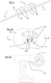
- the system for connecting two catenary contact wires makes it possible to connect the ends of two contact wires 1 placed end to end.
- This connection system comprises a coupling body 2 which accommodates and which holds together the two ends of the contact wire.
- the coupling body is capable of retaining the two contact wires together thanks to first attachment reliefs that this coupling body has for each of the contact wires, these wires contact each having, for their part, a second attachment relief, complementary to one of the first attachment reliefs.
- the second attachment reliefs presented by each of the contact wires are produced without having recourse to the coupling body.
- connection system comprises a tool for preparing the contact wires, independent of the coupling body.
- the shaping die 3 has a deformation relief 31 identical to the first attachment relief.
- the compression means 4 for its part, makes it possible to clamp the shaping die on a contact wire so as to deform the contact wire so that it has a second attachment relief.
- This second attachment relief is thus complementary to the deformation relief and also, consequently, complementary to the first attachment relief.
- the preparation tool makes it possible to prepare a contact wire 1. More specifically, the preparation tool has a housing in which one end of a contact wire 1 is inserted until it comes into abutment against two plates 300.
- the shaping die 3 has a deformation relief 31.
- This deformation relief 31 is broken down into two identical parts to each other.
- a contact wire 1 has, following preparation using a preparation tool, a second attachment relief 11 which is distributed over two opposite faces.
- the shaping die 3 is carried by two support blocks 30. These support blocks 30 are intended to be applied one against the other via the compression means 4. As illustrated by the figure 2b , the compression means 4 comprise a portable autonomous press 40.
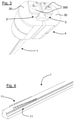
- the coupling body comprises two jaws 20 which are complementary to each other. These jaws are in particular identical to each other. With reference to figure 1 and 6 , these two jaws 20 must be positioned on either side of the two ends placed end to end of two contact wires 1 which must be connected.
- the coupling body then comprises means for assembling and maintaining in an assembled position 21 the two jaws so as to receive and retain together the two contact wires.
- each jaw has a part of the first hooking relief 21 intended to be assembled with the second hooking relief 11 presented by each contact wire 1 (with reference to the figure 4 ).
- first attachment reliefs 21 and the second attachment relief 11 of each contact wire 1 correspond to teeth spaced apart by housings. These teeth and these housings are thus arranged alternately on each relief, and have an inverted, complementary arrangement between the first attachment relief and the second attachment relief. In other words, the teeth of one of the first or of the second attachment relief are anchored in the housings of the other of the first or of the second attachment relief.
- the assembly and holding means 22 in an assembled position comprise bolts 220 with torque failure.
- the assembly and holding means in an assembled position comprise a self-braking washer 221 for each bolt.
- the assembly and holding means in an assembled position consist of a single pair of bolts.
- the coupling body 2 has a visual positioning marker 5. This marker indicates to a person making the connection the distance at which the two contact wires 1 must meet. contact wires and the coupling body are well positioned vis-à-vis.
- the invention also relates to a method for connecting two catenary contact wires. This method implements the connection system previously described.
- connection process comprises two successive steps described below.
- a first step called the deformation step
- two contact wires of a catenary are deformed using the contact wire preparation tool. This deformation consists in creating on each contact wire a second attachment relief which will be complementary to the first attachment reliefs of the coupling body.
- the coupling body is coupled to the two contact wires placed end to end.
- the first attachment reliefs of the coupling body then fit into the second attachment reliefs of the contact wires.
- the first attachment reliefs of the coupling body thus retain the contact wires placed end to end with respect to each other.
Landscapes
- Engineering & Computer Science (AREA)
- Mechanical Engineering (AREA)
- Suspension Of Electric Lines Or Cables (AREA)
- Electric Cable Installation (AREA)
Claims (9)
- Verbindungssystem von zwei Fahrdrähten (1) einer Oberleitung, wobei das System einen Kupplungskörper (2) umfasst, der geeignet ist, zwei aneinandergefügte Fahrdrähte aufzunehmen und gemeinsam zu halten, wobei der Kupplungskörper für jeden der Fahrdrähte ein erstes Einhakrelief (21) aufweist,
dadurch gekennzeichnet, dass er ein Werkzeug zur Vorbereitung der Fahrdrähte umfasst, das vom Kupplungskörper unabhängig ist, wobei das Werkzeug zur Vorbereitung Folgendes umfasst:- eine Formgebungsmatrize (3), die ein Verformungsrelief (31) aufweist, das mit dem ersten Einhakrelief identisch ist;- Druckmittel (4), die mit der Formgebungsmatrize gekoppelt sind, um sie an einem Fahrdraht festzuklemmen und den Fahrdraht so zu verformen, dass er ein zweites Einhakrelief (11) aufweist, das komplementär zum ersten Einhakrelief ist, wobei der Kupplungskörper nach dem Entfernen des Werkzeugs zur Vorbereitung auf die Fahrdrähte aufgesetzt wird,wobei das Werkzeug zur Vorbereitung der Herstellung jedes zweiten Einhakreliefs auf den Fahrdrähten gewidmet ist, wobei der Kupplungskörper dazu bestimmt ist, die Verbindung dank der ersten Einhakreliefs, die er aufweist, herzustellen. - Verbindungssystem nach Anspruch 1, dadurch gekennzeichnet, dass der Kupplungskörper (2) umfasst:- zwei zueinander komplementäre Backen (20), die dazu bestimmt sind, auf beiden Seiten der beiden aneinandergefügten Enden von zwei zu verbindenden Fahrdrähten (1) positioniert zu werden;- Mittel zum Zusammenbau und zum Halten der beiden Backen in einer zusammengebauten Position (22), um die beiden Fahrdrähte zu erfassen und zusammenzuhalten.
- Verbindungssystem nach Anspruch 2, dadurch gekennzeichnet, dass für jeden Fahrdraht (1) das zweite Einhakrelief (11) auf zwei gegenüberliegende Seiten verteilt ist.
- Verbindungssystem nach einem der Ansprüche 2 und 3, dadurch gekennzeichnet, dass die Backen (20) untereinander identisch sind.
- Verbindungssystem nach einem der Ansprüche 2 bis 4, dadurch gekennzeichnet, dass die Mittel zum Zusammenbau und zum Halten in einer zusammengebauten Position (22) aus einem einzigen Paar Bolzen (220) bestehen.
- Verbindungssystem nach einem der Ansprüche 2 bis 5, dadurch gekennzeichnet, dass die Mittel zum Zusammenbau und zum Halten in einer zusammengebauten Position (22) aus Bolzen (220) mit Drehmomentunterbrechung bestehen.
- Verbindungssystem nach einem der Ansprüche 5 und 6, dadurch gekennzeichnet, dass die Mittel zum Zusammenbau und zum Halten in einer zusammengebauten Position (22) eine selbstbremsende Unterlegscheibe (221) für jeden Bolzen (220) umfassen.
- Verbindungssystem nach einem der vorhergehenden Ansprüche, dadurch gekennzeichnet, dass die Mittel zum Komprimieren (4) eine tragbare, autonome Presse (40) umfassen.
- Verfahren zum Verbinden von zwei Fahrdrähten (1) einer Oberleitung, bei dem ein Verbindungssystem nach einem der vorhergehenden Ansprüche eingesetzt wird, dadurch gekennzeichnet, dass es die folgenden Schritte umfasst:- Verformung von zwei Fahrdrähten einer Oberleitung mit Hilfe eines Werkzeugs zur Vorbereitung der Fahrdrähte, so dass sie jeweils ein zweites Einhakrelief (11) komplementär zu einem der ersten Einhakreliefs (12) eines Kupplungskörpers (2) aufweisen;- Kuppeln des Kupplungskörpers an die beiden Fahrdrähte, wobei die ersten Einhakreliefs des Kupplungskörpers in die zweiten Einhakreliefs der Fahrdrähte einrasten und die aneinandergefügten Fahrdrähte zueinander zurückhalten.
Applications Claiming Priority (2)
| Application Number | Priority Date | Filing Date | Title |
|---|---|---|---|
| FR1657619A FR3054813B1 (fr) | 2016-08-05 | 2016-08-05 | Systeme de raccordement de deux fils de contact de catenaire |
| PCT/FR2017/051915 WO2018024956A1 (fr) | 2016-08-05 | 2017-07-12 | Système de raccordement de deux fils de contact de caténaire |
Publications (2)
| Publication Number | Publication Date |
|---|---|
| EP3494007A1 EP3494007A1 (de) | 2019-06-12 |
| EP3494007B1 true EP3494007B1 (de) | 2022-03-09 |
Family
ID=57348866
Family Applications (1)
| Application Number | Title | Priority Date | Filing Date |
|---|---|---|---|
| EP17754390.7A Active EP3494007B1 (de) | 2016-08-05 | 2017-07-12 | System zur verbindung von zwei fahrleitungskontaktdrähten |
Country Status (3)
| Country | Link |
|---|---|
| EP (1) | EP3494007B1 (de) |
| FR (1) | FR3054813B1 (de) |
| WO (1) | WO2018024956A1 (de) |
Families Citing this family (1)
| Publication number | Priority date | Publication date | Assignee | Title |
|---|---|---|---|---|
| DE102018207897A1 (de) * | 2018-05-18 | 2019-11-21 | Siemens Aktiengesellschaft | Klemme und Fahrdrahtträgeranordnung |
Citations (1)
| Publication number | Priority date | Publication date | Assignee | Title |
|---|---|---|---|---|
| EP1468866A1 (de) * | 2003-04-11 | 2004-10-20 | Bonomi Eugenio S.p.A. | Kupplungshülse fur Fahrleitungen mit voller Zugfestigkeit |
Family Cites Families (5)
| Publication number | Priority date | Publication date | Assignee | Title |
|---|---|---|---|---|
| US1448195A (en) * | 1922-06-03 | 1923-03-13 | Ohio Brass Co | Support for trolley conductors |
| DE1104990B (de) * | 1960-02-06 | 1961-04-20 | Pfisterer Karl | Fahrdrahtstossklemme und bei ihrem Einbau erforderliches Werkzeug |
| FR2048164A5 (de) * | 1969-06-03 | 1971-03-19 | Mauger Robert | |
| FR2845648B1 (fr) | 2002-10-14 | 2005-01-14 | Dubuis Et Cie M | Griffe de renfort ou de jonction pour fil de contact de catenaire |
| JP4414304B2 (ja) * | 2004-08-19 | 2010-02-10 | 東日本旅客鉄道株式会社 | トロリ線接続部の保護金具及び保護金具の固着方法。 |
-
2016
- 2016-08-05 FR FR1657619A patent/FR3054813B1/fr active Active
-
2017
- 2017-07-12 WO PCT/FR2017/051915 patent/WO2018024956A1/fr not_active Ceased
- 2017-07-12 EP EP17754390.7A patent/EP3494007B1/de active Active
Patent Citations (1)
| Publication number | Priority date | Publication date | Assignee | Title |
|---|---|---|---|---|
| EP1468866A1 (de) * | 2003-04-11 | 2004-10-20 | Bonomi Eugenio S.p.A. | Kupplungshülse fur Fahrleitungen mit voller Zugfestigkeit |
Non-Patent Citations (1)
| Title |
|---|
| IRSIGLER M ET AL: "ANWENDUNG VON PRESSVERBINDUNGEN IN OBERLEITUNGSANLAGEN DER OESTERREICHISCHEN BUNDESBAHNEN", EB- ELEKTRISCHE BAHNEN, DIV-DEUTSCHER INDUSTRIEVERLAG, DE, vol. 90, no. 3, 1 March 1992 (1992-03-01), pages 87 - 91, XP000264450, ISSN: 0013-5437 * |
Also Published As
| Publication number | Publication date |
|---|---|
| FR3054813A1 (fr) | 2018-02-09 |
| EP3494007A1 (de) | 2019-06-12 |
| WO2018024956A1 (fr) | 2018-02-08 |
| FR3054813B1 (fr) | 2019-04-19 |
Similar Documents
| Publication | Publication Date | Title |
|---|---|---|
| FR2694453A1 (fr) | Connecteur pour borne de batterie. | |
| EP0342122B1 (de) | Keil für einen elektrischen Abzweigsteckverbinder und elektrischer Abzweigsteckverbinder mit einem solchen Keil | |
| CA2671667C (en) | Connector assembly | |
| FR2639772A1 (fr) | Contact electrique secable hors charge, notamment pour appareil ou vehicules raccordes | |
| EP2706616A1 (de) | Verfahren zum Zusammenbau einer Verbindungsvorrichtung auf einem blanken Endstück eines Elektrokabels, und Einheit, die eine solche fest auf einem Kabelendstück montierte Vorrichtung umfasst | |
| US7385138B2 (en) | Electrical connector with wedges and spring | |
| EP0211741A1 (de) | Anschlussdose mit seitlicher Verbindung | |
| WO2018024956A1 (fr) | Système de raccordement de deux fils de contact de caténaire | |
| FR2941819A1 (fr) | "dispositif pour liaison de masse" | |
| EP0880199B1 (de) | Einsatz zur Verbindung einer elektrischen Anschlussklemme auf einer dünnen Wand und Verfahren zum Montieren und Demontieren | |
| FR2842660A1 (fr) | Procede de sertissage d'un contact sur des brins d'un cable | |
| EP2518831B1 (de) | Anschlussmuffe für elektrische Kabel | |
| FR3144430A1 (fr) | Dispositif de connexion électrique | |
| WO2018115672A1 (fr) | Cosse de raccordement a une batterie | |
| FR2503807A1 (fr) | Vis isolee, notamment pour connecteur electrique | |
| FR2758661A1 (fr) | Dispositif de raccordement mecanique et de connexion electrique | |
| EP2833006A1 (de) | Schraube mit begrenztem Anzugsdrehmoment | |
| KR101230255B1 (ko) | 드롭퍼 클램프 | |
| FR2918806A1 (fr) | Dispositif de raccordement mecanique et de liaison electrique a couple de serrage programme. | |
| JP3452877B2 (ja) | 分岐クランプの矯正方法及びそれに用いる矯正用補助具と矯正用ジグ | |
| FR2799312A1 (fr) | Borne de connexion electrique | |
| FR3063394B1 (fr) | Pince de connexion provisoire | |
| LU82251A1 (fr) | Connecteur por fil de contact catenaire | |
| FR3026065A1 (fr) | Pendule de connexion et son dispositif de suspension | |
| FR3099650A1 (fr) | Contact de puissance à portion de sertissage améliorée |
Legal Events
| Date | Code | Title | Description |
|---|---|---|---|
| STAA | Information on the status of an ep patent application or granted ep patent |
Free format text: STATUS: UNKNOWN |
|
| STAA | Information on the status of an ep patent application or granted ep patent |
Free format text: STATUS: THE INTERNATIONAL PUBLICATION HAS BEEN MADE |
|
| PUAI | Public reference made under article 153(3) epc to a published international application that has entered the european phase |
Free format text: ORIGINAL CODE: 0009012 |
|
| STAA | Information on the status of an ep patent application or granted ep patent |
Free format text: STATUS: REQUEST FOR EXAMINATION WAS MADE |
|
| 17P | Request for examination filed |
Effective date: 20190212 |
|
| AK | Designated contracting states |
Kind code of ref document: A1 Designated state(s): AL AT BE BG CH CY CZ DE DK EE ES FI FR GB GR HR HU IE IS IT LI LT LU LV MC MK MT NL NO PL PT RO RS SE SI SK SM TR |
|
| AX | Request for extension of the european patent |
Extension state: BA ME |
|
| DAV | Request for validation of the european patent (deleted) | ||
| DAX | Request for extension of the european patent (deleted) | ||
| STAA | Information on the status of an ep patent application or granted ep patent |
Free format text: STATUS: EXAMINATION IS IN PROGRESS |
|
| 17Q | First examination report despatched |
Effective date: 20200114 |
|
| GRAP | Despatch of communication of intention to grant a patent |
Free format text: ORIGINAL CODE: EPIDOSNIGR1 |
|
| STAA | Information on the status of an ep patent application or granted ep patent |
Free format text: STATUS: GRANT OF PATENT IS INTENDED |
|
| INTG | Intention to grant announced |
Effective date: 20211215 |
|
| GRAS | Grant fee paid |
Free format text: ORIGINAL CODE: EPIDOSNIGR3 |
|
| GRAA | (expected) grant |
Free format text: ORIGINAL CODE: 0009210 |
|
| STAA | Information on the status of an ep patent application or granted ep patent |
Free format text: STATUS: THE PATENT HAS BEEN GRANTED |
|
| AK | Designated contracting states |
Kind code of ref document: B1 Designated state(s): AL AT BE BG CH CY CZ DE DK EE ES FI FR GB GR HR HU IE IS IT LI LT LU LV MC MK MT NL NO PL PT RO RS SE SI SK SM TR |
|
| REG | Reference to a national code |
Ref country code: CH Ref legal event code: EP Ref country code: AT Ref legal event code: REF Ref document number: 1473856 Country of ref document: AT Kind code of ref document: T Effective date: 20220315 |
|
| REG | Reference to a national code |
Ref country code: DE Ref legal event code: R096 Ref document number: 602017054372 Country of ref document: DE |
|
| REG | Reference to a national code |
Ref country code: IE Ref legal event code: FG4D Free format text: LANGUAGE OF EP DOCUMENT: FRENCH |
|
| REG | Reference to a national code |
Ref country code: LT Ref legal event code: MG9D |
|
| REG | Reference to a national code |
Ref country code: NL Ref legal event code: MP Effective date: 20220309 |
|
| PG25 | Lapsed in a contracting state [announced via postgrant information from national office to epo] |
Ref country code: SE Free format text: LAPSE BECAUSE OF FAILURE TO SUBMIT A TRANSLATION OF THE DESCRIPTION OR TO PAY THE FEE WITHIN THE PRESCRIBED TIME-LIMIT Effective date: 20220309 Ref country code: RS Free format text: LAPSE BECAUSE OF FAILURE TO SUBMIT A TRANSLATION OF THE DESCRIPTION OR TO PAY THE FEE WITHIN THE PRESCRIBED TIME-LIMIT Effective date: 20220309 Ref country code: NO Free format text: LAPSE BECAUSE OF FAILURE TO SUBMIT A TRANSLATION OF THE DESCRIPTION OR TO PAY THE FEE WITHIN THE PRESCRIBED TIME-LIMIT Effective date: 20220609 Ref country code: LT Free format text: LAPSE BECAUSE OF FAILURE TO SUBMIT A TRANSLATION OF THE DESCRIPTION OR TO PAY THE FEE WITHIN THE PRESCRIBED TIME-LIMIT Effective date: 20220309 Ref country code: HR Free format text: LAPSE BECAUSE OF FAILURE TO SUBMIT A TRANSLATION OF THE DESCRIPTION OR TO PAY THE FEE WITHIN THE PRESCRIBED TIME-LIMIT Effective date: 20220309 Ref country code: BG Free format text: LAPSE BECAUSE OF FAILURE TO SUBMIT A TRANSLATION OF THE DESCRIPTION OR TO PAY THE FEE WITHIN THE PRESCRIBED TIME-LIMIT Effective date: 20220609 |
|
| REG | Reference to a national code |
Ref country code: AT Ref legal event code: MK05 Ref document number: 1473856 Country of ref document: AT Kind code of ref document: T Effective date: 20220309 |
|
| PG25 | Lapsed in a contracting state [announced via postgrant information from national office to epo] |
Ref country code: LV Free format text: LAPSE BECAUSE OF FAILURE TO SUBMIT A TRANSLATION OF THE DESCRIPTION OR TO PAY THE FEE WITHIN THE PRESCRIBED TIME-LIMIT Effective date: 20220309 Ref country code: GR Free format text: LAPSE BECAUSE OF FAILURE TO SUBMIT A TRANSLATION OF THE DESCRIPTION OR TO PAY THE FEE WITHIN THE PRESCRIBED TIME-LIMIT Effective date: 20220610 Ref country code: FI Free format text: LAPSE BECAUSE OF FAILURE TO SUBMIT A TRANSLATION OF THE DESCRIPTION OR TO PAY THE FEE WITHIN THE PRESCRIBED TIME-LIMIT Effective date: 20220309 |
|
| PG25 | Lapsed in a contracting state [announced via postgrant information from national office to epo] |
Ref country code: NL Free format text: LAPSE BECAUSE OF FAILURE TO SUBMIT A TRANSLATION OF THE DESCRIPTION OR TO PAY THE FEE WITHIN THE PRESCRIBED TIME-LIMIT Effective date: 20220309 |
|
| PG25 | Lapsed in a contracting state [announced via postgrant information from national office to epo] |
Ref country code: SM Free format text: LAPSE BECAUSE OF FAILURE TO SUBMIT A TRANSLATION OF THE DESCRIPTION OR TO PAY THE FEE WITHIN THE PRESCRIBED TIME-LIMIT Effective date: 20220309 Ref country code: SK Free format text: LAPSE BECAUSE OF FAILURE TO SUBMIT A TRANSLATION OF THE DESCRIPTION OR TO PAY THE FEE WITHIN THE PRESCRIBED TIME-LIMIT Effective date: 20220309 Ref country code: RO Free format text: LAPSE BECAUSE OF FAILURE TO SUBMIT A TRANSLATION OF THE DESCRIPTION OR TO PAY THE FEE WITHIN THE PRESCRIBED TIME-LIMIT Effective date: 20220309 Ref country code: PT Free format text: LAPSE BECAUSE OF FAILURE TO SUBMIT A TRANSLATION OF THE DESCRIPTION OR TO PAY THE FEE WITHIN THE PRESCRIBED TIME-LIMIT Effective date: 20220711 Ref country code: ES Free format text: LAPSE BECAUSE OF FAILURE TO SUBMIT A TRANSLATION OF THE DESCRIPTION OR TO PAY THE FEE WITHIN THE PRESCRIBED TIME-LIMIT Effective date: 20220309 Ref country code: EE Free format text: LAPSE BECAUSE OF FAILURE TO SUBMIT A TRANSLATION OF THE DESCRIPTION OR TO PAY THE FEE WITHIN THE PRESCRIBED TIME-LIMIT Effective date: 20220309 Ref country code: CZ Free format text: LAPSE BECAUSE OF FAILURE TO SUBMIT A TRANSLATION OF THE DESCRIPTION OR TO PAY THE FEE WITHIN THE PRESCRIBED TIME-LIMIT Effective date: 20220309 Ref country code: AT Free format text: LAPSE BECAUSE OF FAILURE TO SUBMIT A TRANSLATION OF THE DESCRIPTION OR TO PAY THE FEE WITHIN THE PRESCRIBED TIME-LIMIT Effective date: 20220309 |
|
| PG25 | Lapsed in a contracting state [announced via postgrant information from national office to epo] |
Ref country code: PL Free format text: LAPSE BECAUSE OF FAILURE TO SUBMIT A TRANSLATION OF THE DESCRIPTION OR TO PAY THE FEE WITHIN THE PRESCRIBED TIME-LIMIT Effective date: 20220309 Ref country code: IS Free format text: LAPSE BECAUSE OF FAILURE TO SUBMIT A TRANSLATION OF THE DESCRIPTION OR TO PAY THE FEE WITHIN THE PRESCRIBED TIME-LIMIT Effective date: 20220709 Ref country code: AL Free format text: LAPSE BECAUSE OF FAILURE TO SUBMIT A TRANSLATION OF THE DESCRIPTION OR TO PAY THE FEE WITHIN THE PRESCRIBED TIME-LIMIT Effective date: 20220309 |
|
| REG | Reference to a national code |
Ref country code: DE Ref legal event code: R097 Ref document number: 602017054372 Country of ref document: DE |
|
| PLBE | No opposition filed within time limit |
Free format text: ORIGINAL CODE: 0009261 |
|
| STAA | Information on the status of an ep patent application or granted ep patent |
Free format text: STATUS: NO OPPOSITION FILED WITHIN TIME LIMIT |
|
| PG25 | Lapsed in a contracting state [announced via postgrant information from national office to epo] |
Ref country code: DK Free format text: LAPSE BECAUSE OF FAILURE TO SUBMIT A TRANSLATION OF THE DESCRIPTION OR TO PAY THE FEE WITHIN THE PRESCRIBED TIME-LIMIT Effective date: 20220309 |
|
| REG | Reference to a national code |
Ref country code: DE Ref legal event code: R119 Ref document number: 602017054372 Country of ref document: DE |
|
| 26N | No opposition filed |
Effective date: 20221212 |
|
| PG25 | Lapsed in a contracting state [announced via postgrant information from national office to epo] |
Ref country code: SI Free format text: LAPSE BECAUSE OF FAILURE TO SUBMIT A TRANSLATION OF THE DESCRIPTION OR TO PAY THE FEE WITHIN THE PRESCRIBED TIME-LIMIT Effective date: 20220309 Ref country code: MC Free format text: LAPSE BECAUSE OF FAILURE TO SUBMIT A TRANSLATION OF THE DESCRIPTION OR TO PAY THE FEE WITHIN THE PRESCRIBED TIME-LIMIT Effective date: 20220309 |
|
| GBPC | Gb: european patent ceased through non-payment of renewal fee |
Effective date: 20220712 |
|
| PG25 | Lapsed in a contracting state [announced via postgrant information from national office to epo] |
Ref country code: GB Free format text: LAPSE BECAUSE OF NON-PAYMENT OF DUE FEES Effective date: 20220712 Ref country code: DE Free format text: LAPSE BECAUSE OF NON-PAYMENT OF DUE FEES Effective date: 20230201 |
|
| PG25 | Lapsed in a contracting state [announced via postgrant information from national office to epo] |
Ref country code: IT Free format text: LAPSE BECAUSE OF FAILURE TO SUBMIT A TRANSLATION OF THE DESCRIPTION OR TO PAY THE FEE WITHIN THE PRESCRIBED TIME-LIMIT Effective date: 20220309 Ref country code: IE Free format text: LAPSE BECAUSE OF NON-PAYMENT OF DUE FEES Effective date: 20220712 |
|
| PG25 | Lapsed in a contracting state [announced via postgrant information from national office to epo] |
Ref country code: HU Free format text: LAPSE BECAUSE OF FAILURE TO SUBMIT A TRANSLATION OF THE DESCRIPTION OR TO PAY THE FEE WITHIN THE PRESCRIBED TIME-LIMIT; INVALID AB INITIO Effective date: 20170712 |
|
| PG25 | Lapsed in a contracting state [announced via postgrant information from national office to epo] |
Ref country code: MK Free format text: LAPSE BECAUSE OF FAILURE TO SUBMIT A TRANSLATION OF THE DESCRIPTION OR TO PAY THE FEE WITHIN THE PRESCRIBED TIME-LIMIT Effective date: 20220309 Ref country code: CY Free format text: LAPSE BECAUSE OF FAILURE TO SUBMIT A TRANSLATION OF THE DESCRIPTION OR TO PAY THE FEE WITHIN THE PRESCRIBED TIME-LIMIT Effective date: 20220309 |
|
| PG25 | Lapsed in a contracting state [announced via postgrant information from national office to epo] |
Ref country code: MT Free format text: LAPSE BECAUSE OF FAILURE TO SUBMIT A TRANSLATION OF THE DESCRIPTION OR TO PAY THE FEE WITHIN THE PRESCRIBED TIME-LIMIT Effective date: 20220309 |
|
| PGFP | Annual fee paid to national office [announced via postgrant information from national office to epo] |
Ref country code: LU Payment date: 20250709 Year of fee payment: 9 |
|
| PGFP | Annual fee paid to national office [announced via postgrant information from national office to epo] |
Ref country code: BE Payment date: 20250709 Year of fee payment: 9 |
|
| PGFP | Annual fee paid to national office [announced via postgrant information from national office to epo] |
Ref country code: FR Payment date: 20250701 Year of fee payment: 9 |
|
| PGFP | Annual fee paid to national office [announced via postgrant information from national office to epo] |
Ref country code: CH Payment date: 20250801 Year of fee payment: 9 |
|
| PG25 | Lapsed in a contracting state [announced via postgrant information from national office to epo] |
Ref country code: TR Free format text: LAPSE BECAUSE OF FAILURE TO SUBMIT A TRANSLATION OF THE DESCRIPTION OR TO PAY THE FEE WITHIN THE PRESCRIBED TIME-LIMIT Effective date: 20220309 |