EP3493712B1 - System and apparatus for preparing a beverage - Google Patents
System and apparatus for preparing a beverage Download PDFInfo
- Publication number
- EP3493712B1 EP3493712B1 EP17754828.6A EP17754828A EP3493712B1 EP 3493712 B1 EP3493712 B1 EP 3493712B1 EP 17754828 A EP17754828 A EP 17754828A EP 3493712 B1 EP3493712 B1 EP 3493712B1
- Authority
- EP
- European Patent Office
- Prior art keywords
- capsule
- brew chamber
- chamber part
- rim
- abutment surface
- Prior art date
- Legal status (The legal status is an assumption and is not a legal conclusion. Google has not performed a legal analysis and makes no representation as to the accuracy of the status listed.)
- Active
Links
- 235000013361 beverage Nutrition 0.000 title claims description 57
- 239000002775 capsule Substances 0.000 claims description 300
- 238000000605 extraction Methods 0.000 claims description 30
- 230000002093 peripheral effect Effects 0.000 claims description 23
- 239000007788 liquid Substances 0.000 claims description 12
- 230000004323 axial length Effects 0.000 claims description 11
- 230000001419 dependent effect Effects 0.000 claims 1
- 238000007789 sealing Methods 0.000 description 41
- 239000012530 fluid Substances 0.000 description 20
- 239000011888 foil Substances 0.000 description 11
- 239000000463 material Substances 0.000 description 10
- 210000000629 knee joint Anatomy 0.000 description 8
- 238000007373 indentation Methods 0.000 description 7
- -1 polypropylene Polymers 0.000 description 7
- XLYOFNOQVPJJNP-UHFFFAOYSA-N water Substances O XLYOFNOQVPJJNP-UHFFFAOYSA-N 0.000 description 7
- 229910052782 aluminium Inorganic materials 0.000 description 5
- XAGFODPZIPBFFR-UHFFFAOYSA-N aluminium Chemical compound [Al] XAGFODPZIPBFFR-UHFFFAOYSA-N 0.000 description 5
- 230000015572 biosynthetic process Effects 0.000 description 5
- 238000005755 formation reaction Methods 0.000 description 5
- 239000004615 ingredient Substances 0.000 description 5
- 210000003813 thumb Anatomy 0.000 description 5
- 238000010276 construction Methods 0.000 description 4
- 230000000694 effects Effects 0.000 description 4
- 230000005484 gravity Effects 0.000 description 4
- 238000000034 method Methods 0.000 description 4
- 239000002699 waste material Substances 0.000 description 4
- 239000004698 Polyethylene Substances 0.000 description 3
- 239000004743 Polypropylene Substances 0.000 description 3
- 230000000875 corresponding effect Effects 0.000 description 3
- 229910052751 metal Inorganic materials 0.000 description 3
- 239000002184 metal Substances 0.000 description 3
- 239000004033 plastic Substances 0.000 description 3
- 229920003023 plastic Polymers 0.000 description 3
- 229920000573 polyethylene Polymers 0.000 description 3
- 229920001155 polypropylene Polymers 0.000 description 3
- 238000001125 extrusion Methods 0.000 description 2
- 238000001746 injection moulding Methods 0.000 description 2
- 238000003780 insertion Methods 0.000 description 2
- 230000037431 insertion Effects 0.000 description 2
- 210000003127 knee Anatomy 0.000 description 2
- 238000012986 modification Methods 0.000 description 2
- 230000004048 modification Effects 0.000 description 2
- 229920000728 polyester Polymers 0.000 description 2
- 229920000139 polyethylene terephthalate Polymers 0.000 description 2
- 239000005020 polyethylene terephthalate Substances 0.000 description 2
- 229920000642 polymer Polymers 0.000 description 2
- 238000007666 vacuum forming Methods 0.000 description 2
- 230000000007 visual effect Effects 0.000 description 2
- 241001122767 Theaceae Species 0.000 description 1
- 229920002988 biodegradable polymer Polymers 0.000 description 1
- 239000004621 biodegradable polymer Substances 0.000 description 1
- 238000000071 blow moulding Methods 0.000 description 1
- 230000002596 correlated effect Effects 0.000 description 1
- 239000002657 fibrous material Substances 0.000 description 1
- 210000003811 finger Anatomy 0.000 description 1
- 235000013305 food Nutrition 0.000 description 1
- 229910001092 metal group alloy Inorganic materials 0.000 description 1
- 229920000098 polyolefin Polymers 0.000 description 1
- 229920000915 polyvinyl chloride Polymers 0.000 description 1
- 239000004800 polyvinyl chloride Substances 0.000 description 1
- 238000002360 preparation method Methods 0.000 description 1
- 238000003825 pressing Methods 0.000 description 1
- 239000010935 stainless steel Substances 0.000 description 1
- 229910001220 stainless steel Inorganic materials 0.000 description 1
- 239000000126 substance Substances 0.000 description 1
- 239000012815 thermoplastic material Substances 0.000 description 1
- 238000003466 welding Methods 0.000 description 1
Images


Classifications
-
- A—HUMAN NECESSITIES
- A47—FURNITURE; DOMESTIC ARTICLES OR APPLIANCES; COFFEE MILLS; SPICE MILLS; SUCTION CLEANERS IN GENERAL
- A47J—KITCHEN EQUIPMENT; COFFEE MILLS; SPICE MILLS; APPARATUS FOR MAKING BEVERAGES
- A47J31/00—Apparatus for making beverages
- A47J31/24—Coffee-making apparatus in which hot water is passed through the filter under pressure, i.e. in which the coffee grounds are extracted under pressure
- A47J31/34—Coffee-making apparatus in which hot water is passed through the filter under pressure, i.e. in which the coffee grounds are extracted under pressure with hot water under liquid pressure
- A47J31/36—Coffee-making apparatus in which hot water is passed through the filter under pressure, i.e. in which the coffee grounds are extracted under pressure with hot water under liquid pressure with mechanical pressure-producing means
- A47J31/3604—Coffee-making apparatus in which hot water is passed through the filter under pressure, i.e. in which the coffee grounds are extracted under pressure with hot water under liquid pressure with mechanical pressure-producing means with a mechanism arranged to move the brewing chamber between loading, infusing and ejecting stations
- A47J31/3623—Cartridges being employed
- A47J31/3633—Means to perform transfer from a loading position to an infusing position
-
- A—HUMAN NECESSITIES
- A47—FURNITURE; DOMESTIC ARTICLES OR APPLIANCES; COFFEE MILLS; SPICE MILLS; SUCTION CLEANERS IN GENERAL
- A47J—KITCHEN EQUIPMENT; COFFEE MILLS; SPICE MILLS; APPARATUS FOR MAKING BEVERAGES
- A47J31/00—Apparatus for making beverages
- A47J31/06—Filters or strainers for coffee or tea makers ; Holders therefor
- A47J31/0647—Filters or strainers for coffee or tea makers ; Holders therefor with means to adjust the brewing chamber volume to accommodate different quantities of brewing material
-
- A—HUMAN NECESSITIES
- A47—FURNITURE; DOMESTIC ARTICLES OR APPLIANCES; COFFEE MILLS; SPICE MILLS; SUCTION CLEANERS IN GENERAL
- A47J—KITCHEN EQUIPMENT; COFFEE MILLS; SPICE MILLS; APPARATUS FOR MAKING BEVERAGES
- A47J31/00—Apparatus for making beverages
- A47J31/24—Coffee-making apparatus in which hot water is passed through the filter under pressure, i.e. in which the coffee grounds are extracted under pressure
- A47J31/34—Coffee-making apparatus in which hot water is passed through the filter under pressure, i.e. in which the coffee grounds are extracted under pressure with hot water under liquid pressure
- A47J31/36—Coffee-making apparatus in which hot water is passed through the filter under pressure, i.e. in which the coffee grounds are extracted under pressure with hot water under liquid pressure with mechanical pressure-producing means
- A47J31/3604—Coffee-making apparatus in which hot water is passed through the filter under pressure, i.e. in which the coffee grounds are extracted under pressure with hot water under liquid pressure with mechanical pressure-producing means with a mechanism arranged to move the brewing chamber between loading, infusing and ejecting stations
- A47J31/3623—Cartridges being employed
- A47J31/3628—Perforating means therefor
-
- A—HUMAN NECESSITIES
- A47—FURNITURE; DOMESTIC ARTICLES OR APPLIANCES; COFFEE MILLS; SPICE MILLS; SUCTION CLEANERS IN GENERAL
- A47J—KITCHEN EQUIPMENT; COFFEE MILLS; SPICE MILLS; APPARATUS FOR MAKING BEVERAGES
- A47J31/00—Apparatus for making beverages
- A47J31/24—Coffee-making apparatus in which hot water is passed through the filter under pressure, i.e. in which the coffee grounds are extracted under pressure
- A47J31/34—Coffee-making apparatus in which hot water is passed through the filter under pressure, i.e. in which the coffee grounds are extracted under pressure with hot water under liquid pressure
- A47J31/36—Coffee-making apparatus in which hot water is passed through the filter under pressure, i.e. in which the coffee grounds are extracted under pressure with hot water under liquid pressure with mechanical pressure-producing means
- A47J31/3604—Coffee-making apparatus in which hot water is passed through the filter under pressure, i.e. in which the coffee grounds are extracted under pressure with hot water under liquid pressure with mechanical pressure-producing means with a mechanism arranged to move the brewing chamber between loading, infusing and ejecting stations
- A47J31/3623—Cartridges being employed
- A47J31/3638—Means to eject the cartridge after brewing
-
- A—HUMAN NECESSITIES
- A47—FURNITURE; DOMESTIC ARTICLES OR APPLIANCES; COFFEE MILLS; SPICE MILLS; SUCTION CLEANERS IN GENERAL
- A47J—KITCHEN EQUIPMENT; COFFEE MILLS; SPICE MILLS; APPARATUS FOR MAKING BEVERAGES
- A47J31/00—Apparatus for making beverages
- A47J31/24—Coffee-making apparatus in which hot water is passed through the filter under pressure, i.e. in which the coffee grounds are extracted under pressure
- A47J31/34—Coffee-making apparatus in which hot water is passed through the filter under pressure, i.e. in which the coffee grounds are extracted under pressure with hot water under liquid pressure
- A47J31/36—Coffee-making apparatus in which hot water is passed through the filter under pressure, i.e. in which the coffee grounds are extracted under pressure with hot water under liquid pressure with mechanical pressure-producing means
- A47J31/3666—Coffee-making apparatus in which hot water is passed through the filter under pressure, i.e. in which the coffee grounds are extracted under pressure with hot water under liquid pressure with mechanical pressure-producing means whereby the loading of the brewing chamber with the brewing material is performed by the user
- A47J31/3676—Cartridges being employed
-
- A—HUMAN NECESSITIES
- A47—FURNITURE; DOMESTIC ARTICLES OR APPLIANCES; COFFEE MILLS; SPICE MILLS; SUCTION CLEANERS IN GENERAL
- A47J—KITCHEN EQUIPMENT; COFFEE MILLS; SPICE MILLS; APPARATUS FOR MAKING BEVERAGES
- A47J31/00—Apparatus for making beverages
- A47J31/40—Beverage-making apparatus with dispensing means for adding a measured quantity of ingredients, e.g. coffee, water, sugar, cocoa, milk, tea
- A47J31/407—Beverage-making apparatus with dispensing means for adding a measured quantity of ingredients, e.g. coffee, water, sugar, cocoa, milk, tea with ingredient-containing cartridges; Cartridge-perforating means
-
- A—HUMAN NECESSITIES
- A47—FURNITURE; DOMESTIC ARTICLES OR APPLIANCES; COFFEE MILLS; SPICE MILLS; SUCTION CLEANERS IN GENERAL
- A47J—KITCHEN EQUIPMENT; COFFEE MILLS; SPICE MILLS; APPARATUS FOR MAKING BEVERAGES
- A47J31/00—Apparatus for making beverages
- A47J31/44—Parts or details or accessories of beverage-making apparatus
- A47J31/4403—Constructional details
-
- B—PERFORMING OPERATIONS; TRANSPORTING
- B65—CONVEYING; PACKING; STORING; HANDLING THIN OR FILAMENTARY MATERIAL
- B65D—CONTAINERS FOR STORAGE OR TRANSPORT OF ARTICLES OR MATERIALS, e.g. BAGS, BARRELS, BOTTLES, BOXES, CANS, CARTONS, CRATES, DRUMS, JARS, TANKS, HOPPERS, FORWARDING CONTAINERS; ACCESSORIES, CLOSURES, OR FITTINGS THEREFOR; PACKAGING ELEMENTS; PACKAGES
- B65D85/00—Containers, packaging elements or packages, specially adapted for particular articles or materials
- B65D85/70—Containers, packaging elements or packages, specially adapted for particular articles or materials for materials not otherwise provided for
- B65D85/804—Disposable containers or packages with contents which are mixed, infused or dissolved in situ, i.e. without having been previously removed from the package
- B65D85/8043—Packages adapted to allow liquid to pass through the contents
Definitions
- the invention generally relates to a system for preparing a beverage.
- the invention also relates to an apparatus and method for preparing a beverage. More specifically the invention relates to a system for preparing a beverage using a capsule.
- the invention relates to a system for preparing a quantity of beverage suitable for consumption, including a second exchangeable capsule having a second body with a second flange-like rim and a second exit face attached to the second flange-like rim, and an apparatus for preparing a quantity of beverage suitable for consumption, said apparatus including a first brew chamber part having a cavity for holding the second exchangeable capsule, and a second brew chamber part for closing the first brew chamber part around the second exchangeable capsule, and the first brew chamber part having a first substantially annular abutment surface in the cavity.
- Such a system for preparing a beverage suitable for consumption is known from WO-A1-2015/004613 .
- This known system can use prepackaged capsules having different respective axial lengths.
- the length of a capsule used is recognized mechanically, and the configuration of the brewing chamber is determined accordingly, as a function of the specific shape of the transverse flange of the capsule used on each occasion.
- the flange-like rim of each capsule has at least one indentation or protrusion having a perimetric dimension which is correlated with the axial length or height of said capsule.
- WO-A1-2015/004613 describes capsules having a flange-like rim having indentations with a width that is inversely proportionate to the length of the capsule.
- the brewing unit of the known system comprises a capsule carrier unit having a receiving element including an essentially cup-shaped central part from which a kind of flange extends radially outwards.
- a capsule carrier unit having a receiving element including an essentially cup-shaped central part from which a kind of flange extends radially outwards.
- Two essentially planar appendages, facing one another horizontally, extend vertically upwards from the flange of the receiving element. The appendages extend transversely outwards and are spaced apart from the cup-shaped central portion of the receiving element.
- Respective projecting formations in the shape of isosceles triangles extend from the frontally facing surfaces of the appendages, and the arrangement of these appendages is such that two opposed indentations of the flange of a capsule are initially coupled to, and slide along, the oblique sides of the projecting formations of the appendages.
- this construction e.g. shorter capsules having wider indentations can penetrate farther between the appendages of the capsule carrier unit before its projecting formations bear on and are stopped by the oblique sides of the projecting formations.
- the known apparatus is further constructed such that as soon as the protuberances of the flange-like rim of the capsule begin to interfere with the oblique sides of the projecting formations, the capsule starts to drag the receiving element downwards, and that further rotation of a control lever, together with a number of other components of form a brewing chamber with a dimension adapted to the length of the capsule used such that a beverage can be prepared.
- this known system can be uses to prepare a beverage using prepackaged capsules having different respective axial lengths, the construction of the brewing chamber of which the length is adaptable to the length of the capsule used is relatively complicated. Further, since the flange-like rim of all the capsules used comprises indentations the surface area of the flange-like rim is reduced.
- the contact surface area of the flange-like rim with components of the brewing chamber is reduced, in particular for capsules having a shorter length. Since this contact surface area at least partly provides the sealing between the capsule and the brewing chamber during the brewing operation, the sealing of in particular the capsules of shorter length can be insufficient for using an apparatus in which e.g. hot water is supplied to the capsule under relatively high pressures.
- US2015272375A1 discloses an extraction unit for extracting cartridges of two different dimensions, comprising a seat for receiving any of these cartridges for extraction thereof in the seat.
- the seat is delimited by a first part and second part that are relatively movable between a cartridge extraction position and a cartridge loading and/or ejection position.
- the invention provides a system for preparing a quantity of beverage suitable for consumption, including a first exchangeable capsule having a first body with a first flange-like rime and a first exit face attached to the first flange-like rim, a second exchangeable capsule having a second body with a second flange-like rim and a second exit face attached to the second flange-like rim, wherein the second flange-like rim has a larger diameter than the first flange-like rim, and an apparatus for preparing a quantity of beverage suitable for consumption, said apparatus including a first brew chamber part having a cavity for selectively holding the first or the second exchangeable capsule, and a second brew chamber part for closing the first brew chamber part around the first or second exchangeable capsule, and the first brew chamber part having a first substantially annular abutment surface in the cavity arranged for abutting the first flange-like rim there against when the cavity holds the
- the system can be constructed in a relatively simple manner to prepare a quantity of beverage suitable for consumption selectively using a first exchangeable capsule having a flange-like rim dimensioned to abut the first annular abutment surface and a second exchangeable capsule having a flange-like rim dimensioned to abut the second annular abutment surface.
- exchangeable capsules having different diameters can be used in the inventive system for preparing a quantity of beverage suitable for consumption.
- the first substantially annular abutment surface is spaced from the second substantially annular abutment surface in an axial direction of the first brew chamber part.
- an axial length of the second capsule is larger than an axial length of the first capsule. It is thus possible to use exchangeable capsules having different lengths in the inventive system for preparing a quantity of beverage suitable for consumption.
- An embodiment of the system according to the invention can be constructed in a relatively simple manner and relatively compact when the second substantially annular abutment surface is arranged at an open end of the cavity.
- the cavity of the first brew chamber part can be a predetermined cavity arranged for holding the first or second capsule.
- the cavity can have an invariable shape for holding the first or second capsule.
- the first brew chamber part can be arranged for holding the first or second capsule without changing a configuration of the first brew chamber part.
- the first brew chamber part can be a monolithic part.
- the second brew chamber part has an extraction plate for selectively abutting against the first or second exit face. It is then advantageous from a constructional point of view when the extraction plate includes a central portion and a peripheral portion, the central portion being axially movable relative to the peripheral portion.
- the peripheral portion is arranged to abut against the second exit face when the cavity holds the second capsule while brewing, which can aid in providing a proper sealing during brewing. The same is valid when the peripheral portion is arranged to abut against the first brew chamber part when the cavity holds the first capsule while brewing.
- the central portion can be arranged to abut against the second exit face when the cavity holds the second capsule while brewing, and the central portion can further be arranged to abut against the first exit face when the cavity holds the first capsule while brewing.
- the system for preparing a quantity of beverage suitable for consumption which can use capsules having different dimensions in which for each capsule the sealing is sufficient during brewing even when liquid is supplied to the capsule at relatively high pressures.
- a liquid supply system is included for supplying liquid to the first brew chamber part, wherein the liquid can enter into an interstice between the first brew chamber part and the second capsule or optionally an interstice between the first brew chamber part and the first capsule.
- the system according to the invention is in particular suitable when first and second exchangeable capsules are used having substantially the same length to diameter ratio.
- the first brew chamber part includes centering means at the bottom of the cavity, wherein the second exchangeable capsule and optionally the first exchangeable capsule are arranged for selectively cooperating with the centering means for selectively centering the first and second exchangeable capsules near the bottom of the cavity.
- the first brew chamber part and the first exchangeable capsule are adapted to each other such that the first exchangeable capsule centers in the cavity by means of the flange-like rim.
- first brew chamber part and the second exchangeable capsule are adapted to each other such that an outer part of the second exchangeable capsule engages the inner circumferential wall of the first brew chamber part when loading the second exchangeable capsule into the first brew chamber part, and wherein the first brew chamber part and the second exchangeable capsule are adapted to each other such that the second exchangeable capsule centers in the cavity by means of the outer part.
- capsules can be centered accurately in the brew chamber part thereby facilitating correct brewing.
- the first and second exchangeable capsule can be easily an correctly inserted into the brew chamber part.
- the second body is a cup-shaped second body including a second bottom and a second circumferential wall, said cup-shaped second body having a second open end, wherein the second flange-like rim is an outwardly extending second rim continuously circumferentially extending along the second open end of the cup-shaped second body, said outwardly extending second rim substantially having a single second width.
- the first body is a cup-shaped first body including a first bottom and a first circumferential wall, said cup-shaped first body having a first open end, wherein the first flange-like rim is an outwardly extending first rim continuously circumferentially extending along the first open end of the cup-shaped first body, said outwardly extending first rim substantially having a single first width.
- Such continuously circumferentially extending rims having a single width can during brewing provide a sufficient seal even in case liquid under pressure is supplied to the capsules.
- the first width and the second width are identical the brew chamber part can be constructed in a relatively easy manner.
- the first generally annular abutment surface can then be continuously annular and the second generally annular abutment surface can then be continuously annular.
- the invention further relates to an apparatus for preparing a predetermined quantity of beverage suitable for consumption, the apparatus being arranged for preparing a predetermined quantity of beverage suitable for consumption selectively using a first exchangeable capsule having a first body and a first flange-like rim or a second exchangeable capsule having a second body and a second flange-like rim, the apparatus including a brew chamber part having a cavity for selectively holding the first or the second exchangeable capsule, the brew chamber part having a first annular abutment surface in the cavity arranged for abutting the first flange-like rim there against when the cavity holds the first exchangeable capsule, wherein the brew chamber part has a second annular abutment surface, the second abutment surface being arranged for abutting the second flange-like rim there against when the cavity holds the second exchangeable capsule and in that a diameter of the second annular abutment surface is larger than a diameter of the first annular abutment surface, characterized
- the apparatus is thus suitable for preparing a predetermined quantity of beverage suitable for consumption using a second exchangeable capsule having a second flange-like rim with a larger diameter than the first flange-like rim.
- first substantially annular abutment surface is spaced from the second substantially annular abutment surface in an axial direction of the first brew chamber part it is possible for the apparatus to use capsules having different lengths.
- the apparatus can be constructed relatively simple when the second substantially annular abutment surface is arranged at an open end of the cavity.
- the second brew chamber part has an extraction plate, which then includes a central portion and a peripheral portion, the central portion being axially movable relative to the peripheral portion.
- the first brew chamber part includes centering means at the bottom of the cavity for correctly centering the capsule in the brew chamber part.
- the first abutment surface provides the cavity with a stepped shape so that capsules of different diameter can be inserted relatively easily.
- the first generally annular abutment surface is continuously annular and wherein the second generally annular abutment surface is continuously annular.
- a capsule and a set of a first and second capsule as described herein.
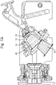
- Figs. 1A and 1B show schematic cross sectional views of a system 1 for preparing a beverage.
- the system includes an apparatus 2 and an exchangeable capsule.
- the system 1 is arranged for cooperating with a first capsule 4A and a second capsule 4B.
- the apparatus 2 shown in Figs. 1A and 1B is one and the same apparatus.
- the apparatus 2 is arranged for selectively cooperating with either the first capsule 4A (see Fig. 1A ) or the second capsule 4B (see Fig. 1B ).
- the system 1 can include the apparatus 2, the first capsule 4A and the second capsule 4B.
- the first and second capsules 4A, 4B are of a different type.
- the second capsule 4B is larger than the first capsule 4A.
- An axial length LB of the second capsule 4B is larger than an axial length LA of the first capsule 4A.
- a diameter DB of the second capsule 4B is a larger than a diameter DA of the first capsule 4A.
- the first and second capsules 4A, 4B are designed to have a family look and feel.
- a ratio of the axial length and diameter LA/DA of the first capsule 4A is substantially the same as a ratio of the axial length and diameter LB/DB of the second capsule 4B.
- the length to diameter ratio of the first and second capsules is identical within 20%, preferably within 10%, e.g. identical.
- the capsules 4A, 4B both include a cup-shaped body 6A, 6B.
- the cup-shaped body 6A, 6B includes a bottom 8A, 8B and a circumferential wall 10A, 10B.
- the bottom 8A, 8B and the circumferential wall 10A, 10B can form a monolithic part.
- the capsules 4A, 4B both include a lid 12A, 12B.
- the lid 12A, 12B closes off an open end of the cup-shaped body 6A, 6B.
- the lid 12A, 12B includes an exit area 13A, 13B through which beverage can be drained from the capsule as explained below.
- the lid 12A, 12B is connected to a flange-like rim 14A, 14B of the capsule 4A, 4B.
- the rim 14A, 14B is an outwardly extending rim.
- the rim 14A, 14B extend continuously circumferentially along the open end, i.e. do not have interruptions or indentations, and each rim 14A, 14B has one and the same width over its periphery, i.e. the rim has a single, uniform width around its circumference.
- the first width of the rim 14A and the second width of the rim 14B can be different from each other, the widths preferably are identical.
- the bottom 8A, 8B, the circumferential wall 10A, 10B and the rim 14A, 14B can form a monolithic part.
- the exit area 13A, 13B defines the area of the lid 12A, 12B through which the beverage can potentially exit the capsule 4A, 4B.
- an area of the lid 12A, 12B sealed to the rim 14A, 14B does not constitute part of the exit area 13A, 13B.
- the capsules 4A, 4B are substantially rotation symmetric around an axis extending from the bottom 8A, 8B to the lid 12A, 12B.
- the cup-shaped body 6A, 6B and the lid 12A, 12B enclose an inner space 16A, 16B of the capsule.
- the inner space 16A, 16B includes a quantity of beverage ingredient, such as an extractable or soluble substance.
- the beverage ingredient can e.g. be roast and ground coffee, tea, or the like.
- the beverage ingredient can be powdered coffee.
- the beverage ingredient can be a liquid.
- the second capsule 4B can include a larger quantity of beverage ingredient than the first capsule 4A.
- the inner space 16B of the second capsule 4B is about twice the inner space 16A of the first capsule 4A.
- the first capsule 4A may include 4-8 grams, e.g. about 6 grams, of ground coffee.
- the second capsule 4B may include 8-16 grams, e.g. about 12 grams, of ground coffee.
- the cup-shaped body 6A, 6B can be manufactured from a metal foil, such as aluminum foil, a plastics material, such as polypropylene or polyethylene, or a combination thereof.
- the cup-shaped body 6A, 6B can be manufactured by pressing, deep-drawing, vacuum forming, injection molding or the like.
- the lid can be manufactured from a metal foil, such as aluminum foil, a plastics material, such as polypropylene or polyethylene, or a combination thereof.
- the capsules 4A, 4B are so-called closed capsules. This indicates capsules that are hermetically closed prior to insertion into the apparatus. The closed capsules can be opened by the apparatus as described below. Alternatively, non-sealed or refillable capsules could also be used.
- the apparatus includes a first brew chamber part 18 and a second brew chamber part 20.
- the first and second brew chamber parts 18, 20 can be closed against each other to form a brew chamber 22A, 22B (not shown in Figs. 1A , 1B ).
- the first brew chamber part 18 includes a cavity 24.
- the cavity 24 is arranged for receiving the first or second capsule 4A, 4B.
- the cavity 24 of the first brew chamber part 18 is a predetermined cavity 24 arranged for holding the first or second capsule 4A, 4B.
- the cavity 24 has an invariable shape for holding the first or second capsule 4A, 4B.
- the first brew chamber part 18 is arranged for holding the first or second capsule 4A, 4B without changing a configuration of the first brew chamber part 18.
- the first brew chamber part 18 is a monolithic part.
- the first brew chamber part 18 includes a first abutment surface 26. The first abutment surface is positioned inside the cavity 24.
- first abutment surface 26 is a first generally annular abutment surface.
- the first generally annular abutment surface 26 can be continuously annular, or it may be interrupted annular, such as comprising a plurality of segments along an annulus.
- the first abutment surface 26 may for example take the shape of one or more, e.g. arched, ridges which protrude into cavity 24.
- the first abutment surface 26 provides the cavity 24 with a stepped shape.
- the first brew chamber part 18 includes a second abutment surface 28.
- the second abutment surface is positioned near the open end of the cavity 24.
- the diameter of the second annular abutment surface 28 is larger than the diameter of the first annular abutment surface 26.
- the second abutment surface 28 is a second generally annular abutment surface.
- the second generally annular abutment surface 28 can be continuously annular, or it may be interrupted annular, such as comprising a plurality of segments along an annulus.
- the second abutment surface 28 may for example take the shape of one or more, e.g. arched, ridges. It will be appreciated that the first abutment surface 26 and the second abutment surface 28 are spaced at a mutual distance in an axial direction of the first brew chamber part 18.
- the first abutment surface 26 and the second abutment surface 28 are positioned at a fixed spacing.
- the first abutment surface 26 and the second abutment surface are immobile relative to each other.
- the first brew chamber part 18 includes an ejector 38.
- the ejector 38 includes a conical ring and/or a resilient element 42, here a helical spring.
- the first brew chamber part 18 includes piercing means 44 for piercing the bottom of the capsule.
- the piercing means includes a plurality of knives, such as three knives.
- the second brew chamber part 20 includes an extraction plate 30.
- the extraction plate 30 includes a central portion 32 and a peripheral portion 34.
- the central portion 32 is movable relative to the peripheral portion 34.
- the central portion 32 is movable in an axial direction of the second brew chamber part 20.
- the system 1 as described thus far can be used for preparing a beverage as follows. Further features of the system 1 will be explained along the way.
- FIGs. 1A and 1B the apparatus 2 is in a state ready for receiving a capsule.
- the capsule 4A, 4B has just been inserted into the cavity of the first brew chamber part 18.
- the first brew chamber part 18 is in an inclined position.
- the open end of the cavity 24 points upwards.
- the first capsule 4A can fall into the cavity 24 under the influence of gravity.
- the rim 14A of the first capsule 4A is guided by an inner surface 36 of the first brew chamber part 18.
- the bottom 8A of the first capsule 4A lowers into the cavity 24 until it abuts against the ejector 38.
- the bottom 8A of the first capsule 4A centers on the ejector 38. It will be appreciated that the rim 14A of the first capsule 4A is positioned between the first abutment surface 26 and the second abutment surface 28.
- the bottom 8A of the first capsule 4A is not yet pierced in this state.
- the second capsule 4B can also fall into the cavity 24 under the influence of gravity.
- the circumferential wall 10B of the second capsule 4B is guided by an inner surface 46 of the first brew chamber part 18.
- the bottom 8B of the second capsule 4B lowers into the cavity 24 until it abuts against the ejector 38.
- the bottom 8B of the second capsule 4B centers on the ejector 38. It will be appreciated that the rim 14B of the second capsule 4B is positioned beyond the second abutment surface 28 when seen from the piercing means 44.
- the bottom 8B of the second capsule 4B is not yet pierced in this state.
- the first brew chamber part 18 can be moved towards the second brew chamber part 20 for closing the brew chamber around the capsule 4A, 4B.
- the first brew chamber part 18 is guided in a frame 48 of the apparatus.
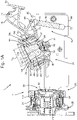
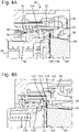
- the first brew chamber part 18 includes first bosses 50 and second bosses 52 as shown in Figs. 2A and 2B .
- the first bosses 50 are guided in a first groove 54 of the frame 48.
- the second bosses 52 are guided in a second groove 56 of the frame 48.
- the bosses 50, 52 and grooves 54, 56 determine the path that will be followed by the first brew chamber part 18.
- the first groove 54 and the second groove 56 are provided in a side wall 57 of the frame 48.
- the first groove 54 extends into the side wall 57 to a first depth.
- the second groove 56 extends into the side wall to a second depth.
- the second depth is larger than the first depth.
- the first boss 50 has a larger diameter than the second boss 52.
- the first groove 54 has a larger width than the second groove 56.
- the width of the first groove 54 corresponds to the diameter of the first boss 50.
- the width of the second groove 56 corresponds to the width of the second boss 52. It will be appreciated that the first groove 54 extends along a different trajectory than the second groove 56.
- the different widths and depths of the grooves allow the first and second bosses 50, 52 to follow different trajectories. This construction allows a very compact construction for guiding the first and second bosses 50, 52.
- the apparatus 2 includes a lever 58.
- the lever can be actuated manually by a user.
- the lever is pivotally connected to the frame 48 around a lever axis 60.
- the first brew chamber part 18 is connected to the frame 48 via a knee joint 62.
- the knee joint 62 includes a push rod 64 and a crank 66.
- the push rod 64 is pivotally connected to the crank 66 at a knee axis 68.
- the crank 66 is pivotally connected to the frame 48 at a crank axis 70.
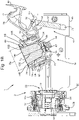
- the lever 58 is connected to the knee joint 62 for actuating the first brew chamber part 18 in motion.
- the lever 58 is connected to the knee joint 62 through a lever link 74.
- the lever link 74 is pivotally connected to the lever 58 at a lever link axis 76.
- the lever link 74 is pivotally connected to the push rod 74 at a knee link axis 78.
- An arresting ring 80 is arranged surrounding the first brew chamber part 18.
- the arresting ring 80 is axially movable relative to the first brew chamber part 18.
- the arresting ring 80 is guided by an external surface of the first brew chamber part 18.
- the arresting ring is connected to the first brew chamber part via one or more resilient elements 82, here helical springs.
- the push rod is pivotally connected to the arresting ring 80 at a push rod axis 72.
- the knee joint 62 is indirectly connected to the first brew chamber part 18, viz. via the arresting ring 80 and one or more resilient elements 82.
- the function of the arresting ring will be set out below.
- the lever 58 When the lever 58 is moved in a downward direction the knee joint 62 will push the first brew chamber part 18 towards the second brew chamber part 20. Simultaneously, due to the shape of the first and second grooves 54, 56, the first brew chamber part 18 will be rotated from the upwards inclined orientation into a an aligned orientation in which an axial direction of the first brew chamber part 18 is aligned with an axial direction of the second brew chamber part 20.
- the apparatus 2 is arranged for selectively cooperating with either the first capsule 4A or the second capsule 4B.
- the system 1 is arranged for automatically adjusting the brew chamber depending on whether the first or the second capsule has been inserted. This provides the advantage that no user input is required for selecting proper handling of the first or second capsule. Hence, the risk of errors is greatly reduced.
- the second brew chamber part 20 includes an extraction plate 30 with a central portion 32 and a peripheral portion 34.
- the central portion 32 is movable in an axial direction of the second brew chamber part 20.
- the central portion 32 in this example includes a shaft 32' axially slidably movable with respect to the frame 48.
- the central portion 32 is connected to the frame 48 via a resilient member 84, here a helical spring.
- the resilient member 84 biases the central portion 32 into a ready position in Figs. 1A and 1B .
- the ready position is an extended position in this example.
- the central portion 32 can be positioned in a first brewing position for cooperating with the first capsule 4A.
- the central portion 32 can be positioned in a second brewing position for cooperating with the second capsule 4B.
- the system 1 includes a locking mechanism 86 arranged for locking the central portion 32 in or near the first brewing position when the cavity 24 holds the first capsule 4A.
- the locking mechanism 86 includes a locker 88.
- the locker 88 is designed as a pivotable finger, pivotable around a pivoting axis 90.
- the locker 88 is biased into a position pivoted away from the shaft 32'.
- the locker could also be biased into any other suitable position.
- the locking mechanism 86 further includes a pusher 92.
- the pusher is slidably guided in a body 94 of the second brew part 20.
- the pusher 92 is connected to the body 94 via a resilient member 96, here a helical spring.
- the resilient member 96 biases the pusher in an extended position.
- the first brew chamber part 18 includes an actuator 98.
- the actuator is formed by a frontal surface of the first brew chamber part 18.
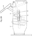
- Figs. 3A and 3B show functioning of the locking mechanism 86 when the cavity 24 holds the first capsule 4A.
- an outermost part of the first capsule 4A here formed by the lid 12A, exit area 13A and/or rim 14A, is positioned rearwardly, i.e. more towards the piercing means 44, relative to the actuator 98.
- the actuator 98 will touch the pusher 92 before the outermost part of the first capsule 4A will touch the central portion 32.
- the pusher is pushed against the biasing force of the resilient member 96.
- a lip 100 of the pusher 92 will slide along a sloping surface 102 of the locker 88, causing the locker 88 to pivot towards the shaft 32'.
- a thumb 104 of the locker 88 is placed in a path of movement of part 106 of the central portion 32 (see Fig. 3B ).
- the pivoted locker 88 prevents travel of the central portion 32 beyond a position where the part 106 abuts against the thumb 104. This is herein defined as the first brewing position.
- the first capsule 4A is arranged for moving the central portion 32 from the ready position to the first brewing position.
- the first capsule 4A is held between the first and second brew chamber parts 18, 20 while brewing, wherein the central portion 32 is in the first brewing position.
- Figs. 4A and 4B show functioning of the locking mechanism 86 when the cavity 24 holds the second capsule 4B.
- an outermost part of the second capsule 4B here formed by the lid 12B, exit area 13B and/or rim 14B, is positioned forwardly, i.e. more towards the second brew chamber part 20, relative to the actuator 98.
- the outermost part of the second capsule 4B will abut against the central portion 32 before the actuator 98 will touch the pusher 92.
- the central portion 32 is pushed against the biasing force of the resilient member 84 while the locker 88 is still pivoted away from the shaft 32'.
- the part 106 passed underneath the thumb 104. Only after the part 106 has passed the thumb 104 the pusher is pushed against the biasing force of the resilient member 96 by the actuator 98. The lip 100 of the pusher 92 will still slide along the sloping surface 102 of the locker 88, causing the locker 88 to pivot towards the shaft 32'. However, the part 106 has already passed the thumb 104 at that moment.
- the second capsule 4B pushes the central portion 32 in abutment with the body 94. This is herein defined as the second brewing position.
- the second capsule 4B is arranged for moving the central portion 32 from the ready position to the second brewing position.
- the second capsule 4B is held between the first and second brew chamber parts 18, 20 while brewing, wherein the central portion 32 is in the second brewing position.
- the locking mechanism 86 is arranged for locking the central portion 32 in the first brewing position when the cavity 24 holds the first capsule 4A. It is noted that the locking may be single-sided, viz. the locking mechanism may prevent the central portion 32 from being moved beyond the first brewing position when the cavity 24 holds the first capsule 4A. However movement of the central portion 32 from the first brewing position to the ready position may be not prevented.
- the locking unit 86 is arranged for selectively preventing the central portion 32 being locked in or near the first brewing position when the second capsule 4B is included in the brew chamber.
- the locking unit 86 is arranged for selectively allowing the central portion 32 being moved into the second brewing position when the second capsule is included in the brew chamber.
- the central portion 32 extends into the cavity 24.
- the central portion 32 extends into the first brew chamber part 18 beyond a position where the lid 12B, exit area 13B and/or rim 14B of the second capsule 4B would have been, had the second capsule been included in the first brew chamber part 18.
- the knee joint 62 is indirectly connected to the first brew chamber part 18, viz. via the arresting ring 80 and one or more resilient elements 82.
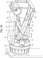
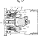
- Figs. 5A-5C demonstrate functioning of the arresting ring 80.
- the first brew chamber part 18 includes a protrusion 108.
- the protrusion 108 is a substantially annular protrusion.
- the protrusion 108 extends outwardly.
- the protrusion 108 forms an outermost edge of the first brew chamber part 18.
- the second brew chamber part 20 includes a retainer 110.
- the retainer 110 is designed as a circumferential ring of retainer lips.
- the retainer 110 is pivotally connected to the body 94.
- the retainer 110 is resiliently pivotally connected to the body 94.
- the retainer 110 includes a tooth 112.
- the tooth here has a first inclined surface 114 and a second inclined surface 116.
- the arresting ring 80 When lowering the lever 58, the arresting ring 80 will be advanced towards the second brew chamber part 20.
- the one or more resilient elements 82 will push the first brew chamber part 18 ahead of the arresting ring 80 until the first brew chamber part abuts against the second brew chamber 20 part, e.g. with the capsule 4A, 4B clamped in between.
- the protrusion 108 will advance against the first inclined surface 114. This causes the retainer 110 to be pivoted outwardly (see Fig. 5A ). Further advancing causes the protrusion 108 to pass beyond the second inclined surface 116, causing the retainer 110 to pivot inwardly (see Fig. 5B ).
- the apparatus can include a fluid supply system for supplying a fluid, e.g. a liquid, such as hot water under pressure, to the first brew chamber part 18.
- a fluid e.g. a liquid, such as hot water under pressure
- the first and second brew chamber parts 18, 20 will be pushed away from each other by the fluid pressure.
- the retainer 110 and arresting ring 80, and optionally the locking ring 118, will bear all, or part of, the force exerted by the fluid pressure.
- the arresting ring 80 interposed between the retainer 110 and the locking ring 118 increases mechanical stability.
- the arresting ring 80 does not have to bear all forces exerted onto it by the retainer 110, since it can abut against the locking ring 118 and transmit at least part of the forces to the locking ring 118.
- the locking ring 118 can be immobile, and hence can easily be reinforced. Since the first brew chamber part is locked onto the second brew chamber part 20 the frame 48 and the actuation mechanism, e.g. the knee joint, do not have to bear this force, or at least a smaller part thereof. Hence the frame and/or the actuation mechanism can be designed weaker and/or cheaper.
- arresting ring 80 can function identically with respect to the second capsule 4B.
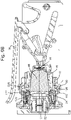
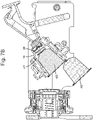
- Fig. 6A shows the first capsule 4A in the brew chamber during extraction.
- Fig. 6B shows the second capsule 4B in the brew chamber during extraction.
- the piercing member 44 is arranged for piercing the bottom 8A, 8B of the capsule 4A, 4B. As can also be seen in Figs. 5A-5C , in this example the piercing member 44 does not pierce the bottom 8A, 8B until the lid 12A, 12B of the capsule 4A, 4B abuts against the central portion 32 in the first or second brewing position.
- stiffnesses of the resilient element 42 and the resilient member 84 can be chosen. In this example, the stiffness of the resilient element 42 is chosen to be larger than the stiffness of the resilient member 84. However, it will be appreciated that it is also possible that the stiffness of the resilient element 42 is equal to the stiffness of the resilient member 84 or that the stiffness of the resilient element 42 is smaller than the stiffness of the resilient member 84.
- the beverage preparation apparatus 2 is arranged for preparing a quantity of a beverage, suitable for consumption, using either a first capsule 4A or a second capsule 4B.
- the quantity can be a predetermined quantity.
- the quantity can also be a user selectable, user settable, or user programmable quantity.
- the first sealing member 120 is arranged for providing a fluid sealing engagement between the central portion 32 and the first brew chamber 18 part when forming the brew chamber 22A for holding the first capsule 4A.
- the first sealing member 120 abuts against the first brew chamber part 18 when the first capsule 4A is included in the brew chamber. This provides a seal for water being present in the cavity 24 outside the capsule 4A. This way, brewing fluid injected into the brew chamber 22A, is prevented from bypassing around the outside of the capsule 4A.
- the first sealing member 120 includes a resilient lip 121.
- the resilient lip 121 is arranged to provide a self-reinforcing sealing engagement between the central portion 32 and the first brew chamber part 18 under the effect of fluid pressure in the brew chamber.
- the first sealing member 120 abuts against the rim 14A of the first capsule 4A.
- the rim 14A is pressed against the first sealing member 120 by the first abutment surface 26. This provides a sealing engagement between the central portion 32 and the capsule 4A against beverage exiting the capsule 4A via the exit area 13A. It will be appreciated that here the side of the rim 14A facing away from the cup-shaped body 6A is sealed against the second brew chamber part 20.
- the side of the rim 14A facing towards the cup-shaped body 6A can be sealed against the first brew chamber part 18.
- an additional seal can be provided on the first brew chamber part 18, e.g. on the first abutment surface 26, and/or on the capsule 4A, e.g. on the rim 14A.
- a seal on the capsule may be additional to the seal between the first brew chamber part 18 and the second brew chamber part 20. This may reduce the sealing effort by the first sealing member 120.
- the second sealing member 122 is arranged for providing a fluid sealing engagement between the peripheral portion 34 and the first brew chamber 18 part when forming the brew chamber 22B for holding the second capsule 4B.
- the second sealing member 122 abuts against the first brew chamber part 18 when the second capsule 4B is included in the brew chamber. This provides a seal for water being present in the cavity 24 outside the capsule 4B.
- the second sealing member 122 includes a resilient lip 123.
- the resilient lip 123 is arranged to provide a self-reinforcing sealing engagement between the peripheral portion 34 and the first brew chamber part 18 under the effect of fluid pressure in the brew chamber.
- the second sealing member 122 abuts against the rim 14B of the second capsule 4B.
- the rim 14B is pressed against the second sealing member 122 by the second abutment surface 28. This may provide a sealing engagement between the peripheral portion 34 and the capsule 4B against beverage exiting the capsule 4B via the exit area 13B.
- the first sealing member 120 provides a sealing engagement between the central portion 32 and the peripheral portion 34 when forming the brew chamber 22B for holding the second capsule 4B.
- This sealing engagement between the central portion 32 and the peripheral portion 34 can be self-reinforcing. Thereto the engagement between peripheral portion 34 and the second capsule 4B may allow brewing fluid to pass to the first sealing member 120.
- the first sealing member 120 provides a sealing engagement between the central portion 32 and the capsule 4B against beverage exiting the capsule 4B via the exit area 13B.
- the side of the rim 14B facing away from the cup-shaped body 6B which rim may or may not be covered by a lid, for example by a foil, is sealed against the second brew chamber part 20.
- the side of the rim 14B facing towards the cup-shaped body 6B can be sealed against the first brew chamber part 18.
- first brew chamber part 18 e.g. on the second abutment surface 28, and/or on the capsule 4B, e.g. on the rim 14B.
- a seal on the capsule may be additional to the seal between the first brew chamber part 18 and the second brew chamber part 20. This may reduce the sealing effort by the second sealing member 122.
- the exit area 13A, 13B may open against the extraction plate 30.
- the extraction plate 30 in this example includes a plurality of relief elements 124.
- the relief elements 124 are truncated pyramids. A rise in pressure inside the capsule 4A, 4B can cause the exit area 13A, 13B to tear against the relief elements allowing beverage to exit the capsule 4A, 4B.
- the beverage can pass through the extraction plate 30 via apertures in the extraction plate. Next the beverage can flow to an outlet 126. From the outlet 126 the beverage can flow into a receptacle, such as a cup.
- a receptacle such as a cup.
- the lever 58 can be moved upwardly. This causes the arresting ring 80 to be moved away from the retainer 110.
- the first brew chamber part 18 will be moved rearwardly.
- the second inclined surface 116 of the retainer 110 can allow the retainer to pass the projection 108.
- the first brew chamber 18 part will move away from the second brew chamber part 20.
- the central portion 32 will return to the ready position.
- the bosses 50, 52 and grooves 54, 56 determine the path that will be followed by the first brew chamber part 18.
- the first brew chamber part will swivel downwardly. This promotes ejection of the used capsule 4A, 4B from the cavity 24 under the effect of gravity.
- the ejector 38 can assist in pushing the capsule 4A, 4B off the piercing member 44 and out of the cavity 24.
- the used capsule 4A, 4B can fall into a waste basket of the apparatus 2.
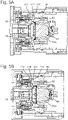
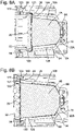
- Fig. 8A shows an example of a first capsule 4A inserted in the brew chamber 22A formed by the first brew chamber part 18 and the second brew chamber part 20. It will be appreciated that the circumferential wall 10A is narrower than the cavity 24 at that location. As a result there is a first volume 126 surrounding the first capsule 4A inside the cavity 24.
- Fig. 8B shows an example of a second capsule 4B inserted in the brew chamber 22B formed by the first brew chamber part 18 and the second brew chamber part 20. It will be appreciated that a part 128 of the circumferential wall 10B is narrower than the cavity 24 at that location. This part 128 is formed by the part of the circumferential wall 10B extending beyond the first abutment surface 26. As a result there is a second volume 130 surrounding the second capsule 4B inside the cavity 24.
- first volume 126 is not occupied by the first capsule 4A when the brew chamber 22A holds the first capsule 4A. However, this first volume 126 is occupied by part of the second capsule 4B when the brew chamber 22B holds the second capsule 4B.
- the second volume 130 is not occupied by the second capsule 4B when the brew chamber holds the second capsule 4B. This second volume 130 receives the central portion 32 of the extraction plate 30 when the brew chamber holds the first capsule 4A.
- the first volume 126 When brewing a beverage using the first capsule 4A, the first volume 126 will fill with fluid, such as water, which fluid is not used for brewing the beverage. This fluid can be drained to the waste basket after brewing.
- the second volume 130 When brewing a beverage using the second capsule 4B, the second volume 130 will fill with fluid, such as water, which fluid is not used for brewing the beverage. This fluid can be drained to a container, e.g. the waste basket, after brewing.
- the first volume 126 is substantially equal to the second volume 130.
- the volume of fluid directed to the waste basket is substantially equal when brewing a beverage using a first capsule 4A and when brewing a beverage using a second capsule 4B.
- the central portion of the extraction plate includes a plurality of relief elements.
- the peripheral portion includes no relief elements.
- the peripheral portion may also include relief elements.
- the extraction plate and the second exit area can be adapted to each other such that a flow resistance of the second exit area when opened is less than a flow resistance of the first exit area when opened.
- the extraction plate and the second exit area may be adapted to each other such that the second exit area tears on the extraction plate over a larger surface area than the first exit area.
- the extraction plate and the second exit area may be adapted to each other such that the second exit area tears on the extraction plate on more locations than the first exit area.
- Outer relief elements may be designed for tearing both the first and second exit area wherein the second exit area tears on the outer relief elements over a larger surface area than the first exit area.
- the extraction plate can include relief elements of a first type and at least one relief element of a second type, wherein the relief elements of the first type are arranged within an area corresponding to the first exit area, and the at least one relief element of the second type being arranged within an area corresponding to the second exit area and outside the area corresponding to the first exit area.
- the relief element of the second type may have a sharper edge than the relief elements of the first type.
- the second exit area may include a weakened zone. The weakened zone may be located in a peripheral area of the second exit area.
- the first and second capsules have substantially the same shape. It is also possible to provide a third capsule having a different shape.
- the third capsule can e.g. be shaped to substantially fill the brew chamber when the central portion is in the first brewing position. It is also possible to provide a fourth capsule having a different shape.
- the fourth capsule can e.g. be shaped to substantially fill the brew chamber when the central portion is in the second extraction position.
- the capsule body and lid are made of aluminum foil, preferable polymer coated aluminum foil to allow easy welding of the lid to the body. It will be appreciated that the capsule body and/or lid can be made of a wide variety of materials considered suitable by the skilled person and capable of being processed into a sheet, film or foil using techniques conventionally known in the art such as extrusion, co-extrusion, injection molding, blow molding, vacuum forming etc.
- Suitable materials for the capsule body and/or lid include, without being limited thereto, plastic materials, in particular thermoplastic materials, for example a polyolefin polymer, for example polyethylene or polypropylene, PVC, polyesters for example polyethylene terephthalate (PET); metal foils such as aluminum, stainless steel, metal alloys etc.; or sheets of a woven or a non-woven or otherwise processed fibrous material, like paper, polyester, etc.; or combinations thereof, e.g. multilayers.
- the material for the capsule can be a biodegradable polymer or another biodegradable material. The skilled person will be capable of selecting the appropriate material taking into account the envisaged use with food material and any other relevant circumstances during use of the capsule.
- the thickness of the sheet or foil may be chosen such that a form stable capsule is provided. The thickness of the sheet or foil may vary with the nature of the material.
- the capsules are closed capsules. It is also possible to provide the system with an open capsule.
- the open capsule is open prior to insertion into the apparatus.
- the open capsule can be pre-perforated.
- the open capsule can be packaged in a hermetically sealed package which has to be removed before inserting the open capsule in the apparatus.
- the capsules are pierced by the piercing means. It is also possible to provide the system with a capsule that is not pierced by the piercing means.
- Such capsule can e.g. include an entrance filter.
- the capsules open against the extraction plate. It is also possible to provide the system with a capsule that does not open against the extraction plate.
- Such capsule can e.g. include an exit filter.
- the capsules themselves do not include a sealing member. It will be appreciated that it is possible to provide the capsule with a sealing member, e.g. a resilient sealing member.
- the sealing member can e.g. be placed on the rim, e.g. on the side facing towards the cup-shaped body or on the side facing away from the cup-shaped body. Alternatively, or additionally, a sealing member can be provided on the circumferential wall and/or on the bottom.
- the arresting ring and retainer extend along substantially the entire perimeter of the first and second brew chamber parts. This provides particular good locking of the two brew chamber parts onto each other.
- the arresting ring and retainer include arresting means and retaining means at one or more discrete positions along the perimeter, e.g. at two, three, four, six or eight positions.
- first apparatus arranged for brewing a beverage using a first capsule, but incapable of brewing a beverage using a second capsule.
- first apparatus can be included in a system with the apparatus as described in relation to the figures and a first capsule and optionally a second capsule.
- Such second apparatus can be included in a system with the apparatus as described in relation to the figures and a second capsule and optionally a first capsule.
- any reference signs placed between parentheses shall not be construed as limiting the claim.
- the word 'comprising' does not exclude the presence of other features or steps than those listed in a claim.
- the words 'a' and 'an' shall not be construed as limited to 'only one', but instead are used to mean 'at least one', and do not exclude a plurality.
- the mere fact that certain measures are recited in mutually different claims does not indicate that a combination of these measures cannot be used to an advantage.
Description
- The invention generally relates to a system for preparing a beverage. The invention also relates to an apparatus and method for preparing a beverage. More specifically the invention relates to a system for preparing a beverage using a capsule. In particular the invention relates to a system for preparing a quantity of beverage suitable for consumption, including a second exchangeable capsule having a second body with a second flange-like rim and a second exit face attached to the second flange-like rim, and an apparatus for preparing a quantity of beverage suitable for consumption, said apparatus including a first brew chamber part having a cavity for holding the second exchangeable capsule, and a second brew chamber part for closing the first brew chamber part around the second exchangeable capsule, and the first brew chamber part having a first substantially annular abutment surface in the cavity.
- Such a system for preparing a beverage suitable for consumption is known from
WO-A1-2015/004613 . This known system can use prepackaged capsules having different respective axial lengths. The length of a capsule used is recognized mechanically, and the configuration of the brewing chamber is determined accordingly, as a function of the specific shape of the transverse flange of the capsule used on each occasion. In particular the flange-like rim of each capsule has at least one indentation or protrusion having a perimetric dimension which is correlated with the axial length or height of said capsule. As an example,WO-A1-2015/004613 describes capsules having a flange-like rim having indentations with a width that is inversely proportionate to the length of the capsule. Thus a capsule having a shorter length has indentations of a larger width. The brewing unit of the known system comprises a capsule carrier unit having a receiving element including an essentially cup-shaped central part from which a kind of flange extends radially outwards. Two essentially planar appendages, facing one another horizontally, extend vertically upwards from the flange of the receiving element. The appendages extend transversely outwards and are spaced apart from the cup-shaped central portion of the receiving element. Respective projecting formations in the shape of isosceles triangles extend from the frontally facing surfaces of the appendages, and the arrangement of these appendages is such that two opposed indentations of the flange of a capsule are initially coupled to, and slide along, the oblique sides of the projecting formations of the appendages. As a result of this construction e.g. shorter capsules having wider indentations can penetrate farther between the appendages of the capsule carrier unit before its projecting formations bear on and are stopped by the oblique sides of the projecting formations. The known apparatus is further constructed such that as soon as the protuberances of the flange-like rim of the capsule begin to interfere with the oblique sides of the projecting formations, the capsule starts to drag the receiving element downwards, and that further rotation of a control lever, together with a number of other components of form a brewing chamber with a dimension adapted to the length of the capsule used such that a beverage can be prepared. Although this known system can be uses to prepare a beverage using prepackaged capsules having different respective axial lengths, the construction of the brewing chamber of which the length is adaptable to the length of the capsule used is relatively complicated. Further, since the flange-like rim of all the capsules used comprises indentations the surface area of the flange-like rim is reduced. As a result the contact surface area of the flange-like rim with components of the brewing chamber is reduced, in particular for capsules having a shorter length. Since this contact surface area at least partly provides the sealing between the capsule and the brewing chamber during the brewing operation, the sealing of in particular the capsules of shorter length can be insufficient for using an apparatus in which e.g. hot water is supplied to the capsule under relatively high pressures. -
US2015272375A1 discloses an extraction unit for extracting cartridges of two different dimensions, comprising a seat for receiving any of these cartridges for extraction thereof in the seat. The seat is delimited by a first part and second part that are relatively movable between a cartridge extraction position and a cartridge loading and/or ejection position. - It thus is an object of the invention to provide a system for preparing a quantity of beverage suitable for consumption which can use capsules having different dimensions in which the brewing chamber can be constructed in a relatively simple manner. It is a further object of the invention to provide a system for preparing a quantity of beverage suitable for consumption which can use capsules having different dimensions in which for each capsule the sealing is sufficient during brewing even when liquid is supplied to the capsule at relatively high pressures. It is still a further object of the invention to provide an alternative system for preparing a quantity of beverage suitable for consumption which can use capsules having different dimensions.
- In order to achieve at least on of the objects identified above the invention provides a system for preparing a quantity of beverage suitable for consumption, including a first exchangeable capsule having a first body with a first flange-like rime and a first exit face attached to the first flange-like rim, a second exchangeable capsule having a second body with a second flange-like rim and a second exit face attached to the second flange-like rim, wherein the second flange-like rim has a larger diameter than the first flange-like rim, and an apparatus for preparing a quantity of beverage suitable for consumption, said apparatus including a first brew chamber part having a cavity for selectively holding the first or the second exchangeable capsule, and a second brew chamber part for closing the first brew chamber part around the first or second exchangeable capsule, and the first brew chamber part having a first substantially annular abutment surface in the cavity arranged for abutting the first flange-like rim there against when the cavity holds the first exchangeable capsule, wherein the first brew chamber part further has a second substantially annular abutment surface arranged for abutting the second flange-like rim there against when the cavity holds the second exchangeable capsule, a diameter of the second annular abutment surface being larger than a diameter of the first annular abutment surface, characterized in that the first substantially annular abutment surface and the second substantially annular abutment surface are immobile relative to each other. By using such a first and a second annular abutment surface the system can be constructed in a relatively simple manner to prepare a quantity of beverage suitable for consumption selectively using a first exchangeable capsule having a flange-like rim dimensioned to abut the first annular abutment surface and a second exchangeable capsule having a flange-like rim dimensioned to abut the second annular abutment surface. Thus exchangeable capsules having different diameters can be used in the inventive system for preparing a quantity of beverage suitable for consumption.
- In an advantageous system according to the invention the first substantially annular abutment surface is spaced from the second substantially annular abutment surface in an axial direction of the first brew chamber part. In particular it is then possible in an embodiment of a system according to the invention that an axial length of the second capsule is larger than an axial length of the first capsule. It is thus possible to use exchangeable capsules having different lengths in the inventive system for preparing a quantity of beverage suitable for consumption.
- An embodiment of the system according to the invention can be constructed in a relatively simple manner and relatively compact when the second substantially annular abutment surface is arranged at an open end of the cavity.
- The cavity of the first brew chamber part can be a predetermined cavity arranged for holding the first or second capsule. The cavity can have an invariable shape for holding the first or second capsule. The first brew chamber part can be arranged for holding the first or second capsule without changing a configuration of the first brew chamber part. The first brew chamber part can be a monolithic part.
- Preferably the second brew chamber part has an extraction plate for selectively abutting against the first or second exit face. It is then advantageous from a constructional point of view when the extraction plate includes a central portion and a peripheral portion, the central portion being axially movable relative to the peripheral portion. Preferably the peripheral portion is arranged to abut against the second exit face when the cavity holds the second capsule while brewing, which can aid in providing a proper sealing during brewing. The same is valid when the peripheral portion is arranged to abut against the first brew chamber part when the cavity holds the first capsule while brewing. The central portion can be arranged to abut against the second exit face when the cavity holds the second capsule while brewing, and the central portion can further be arranged to abut against the first exit face when the cavity holds the first capsule while brewing.
- When the first and/or second brew chamber part is arranged to seal against the second flange-like rim or optionally the first flange-like rim the system for preparing a quantity of beverage suitable for consumption which can use capsules having different dimensions in which for each capsule the sealing is sufficient during brewing even when liquid is supplied to the capsule at relatively high pressures. Preferably a liquid supply system is included for supplying liquid to the first brew chamber part, wherein the liquid can enter into an interstice between the first brew chamber part and the second capsule or optionally an interstice between the first brew chamber part and the first capsule.
- The system according to the invention is in particular suitable when first and second exchangeable capsules are used having substantially the same length to diameter ratio.
- In a further embodiment of a system according to the invention the first brew chamber part includes centering means at the bottom of the cavity, wherein the second exchangeable capsule and optionally the first exchangeable capsule are arranged for selectively cooperating with the centering means for selectively centering the first and second exchangeable capsules near the bottom of the cavity. In a still further embodiment of a system according to the invention the first brew chamber part and the first exchangeable capsule are adapted to each other such that the first exchangeable capsule centers in the cavity by means of the flange-like rim. In an even still further embodiment of a system according to the invention the first brew chamber part and the second exchangeable capsule are adapted to each other such that an outer part of the second exchangeable capsule engages the inner circumferential wall of the first brew chamber part when loading the second exchangeable capsule into the first brew chamber part, and wherein the first brew chamber part and the second exchangeable capsule are adapted to each other such that the second exchangeable capsule centers in the cavity by means of the outer part. In these manners capsules can be centered accurately in the brew chamber part thereby facilitating correct brewing.
- In an embodiment of a system according to the invention in which the first abutment surface provides the cavity with a stepped shape, the first and second exchangeable capsule can be easily an correctly inserted into the brew chamber part.
- In a further embodiment of a system according to the invention the second body is a cup-shaped second body including a second bottom and a second circumferential wall, said cup-shaped second body having a second open end, wherein the second flange-like rim is an outwardly extending second rim continuously circumferentially extending along the second open end of the cup-shaped second body, said outwardly extending second rim substantially having a single second width. Preferably, the first body is a cup-shaped first body including a first bottom and a first circumferential wall, said cup-shaped first body having a first open end, wherein the first flange-like rim is an outwardly extending first rim continuously circumferentially extending along the first open end of the cup-shaped first body, said outwardly extending first rim substantially having a single first width. Such continuously circumferentially extending rims having a single width can during brewing provide a sufficient seal even in case liquid under pressure is supplied to the capsules. In case the first width and the second width are identical the brew chamber part can be constructed in a relatively easy manner. In particular the first generally annular abutment surface can then be continuously annular and the second generally annular abutment surface can then be continuously annular.
- The invention further relates to an apparatus for preparing a predetermined quantity of beverage suitable for consumption, the apparatus being arranged for preparing a predetermined quantity of beverage suitable for consumption selectively using a first exchangeable capsule having a first body and a first flange-like rim or a second exchangeable capsule having a second body and a second flange-like rim, the apparatus including a brew chamber part having a cavity for selectively holding the first or the second exchangeable capsule, the brew chamber part having a first annular abutment surface in the cavity arranged for abutting the first flange-like rim there against when the cavity holds the first exchangeable capsule, wherein the brew chamber part has a second annular abutment surface, the second abutment surface being arranged for abutting the second flange-like rim there against when the cavity holds the second exchangeable capsule and in that a diameter of the second annular abutment surface is larger than a diameter of the first annular abutment surface, characterized in that the first substantially annular abutment surface and the second substantially annular abutment surface are immobile relative to each other. The apparatus is thus suitable for preparing a predetermined quantity of beverage suitable for consumption using a second exchangeable capsule having a second flange-like rim with a larger diameter than the first flange-like rim. In case the first substantially annular abutment surface is spaced from the second substantially annular abutment surface in an axial direction of the first brew chamber part it is possible for the apparatus to use capsules having different lengths.
- The apparatus can be constructed relatively simple when the second substantially annular abutment surface is arranged at an open end of the cavity.
- Preferably the second brew chamber part has an extraction plate, which then includes a central portion and a peripheral portion, the central portion being axially movable relative to the peripheral portion.
- In an embodiment of an apparatus according to the invention the first brew chamber part includes centering means at the bottom of the cavity for correctly centering the capsule in the brew chamber part.
- In a further embodiment of an apparatus according to the invention the first abutment surface provides the cavity with a stepped shape so that capsules of different diameter can be inserted relatively easily. In order to provide a correct sealing even when liquid under pressure is used for brewing the beverage it is preferred that the first generally annular abutment surface is continuously annular and wherein the second generally annular abutment surface is continuously annular.
- According to an aspect is provided a method for preparing a quantity of beverage suitable for consumption as described herein.
- According to an aspect is provided a capsule, and a set of a first and second capsule as described herein.
- It will be appreciated that any of the embodiments, aspects, features and options described in view of the system apply equally to the apparatus, capsules and method. It will also be clear that any one or more of the above embodiments, aspects, features and options can be combined.
- The invention will further be elucidated on the basis of exemplary embodiments which are represented in a drawing. The exemplary embodiments are given by way of non-limitative illustration. It is noted that the figures are only schematic representations of embodiments of the invention that are given by way of non-limiting example.
- In the drawing:
-
Figs. 1A and1B show schematic representations of a system according to the invention; -
Figs. 2A and2B show the first brew chamber part of the system ofFigs. 1 A and 1B in more detail; -
Figs. 3A and 3B show the functioning of the locking mechanism of the system as shown inFig. 1A when the cavity holds the first capsule; -
Figs. 4A and 4B show the functioning of the locking mechanism of the system as shown inFig. 1B when the cavity holds the second capsule; -
Figs. 5A, 5B and5C show the functioning of the arresting ring of the system as shown inFig. 1A when the cavity holds the first capsule; -
Figs. 6A and6B show the first capsule in the brew chamber during extraction and the second capsule in the brew chamber during extraction, respectively; -
Figs. 7A and7B show the first brew chamber part swiveled downwards for ejection of the used first and second capsule, respectively, from the cavity under the effect of gravity; and -
Figs. 8A and 8B show an example of a first capsule and second capsule, respectively, inserted in the brew chamber formed by the first brew chamber part and the second brew chamber part. -
Figs. 1A and1B show schematic cross sectional views of asystem 1 for preparing a beverage. The system includes anapparatus 2 and an exchangeable capsule. Here thesystem 1 is arranged for cooperating with afirst capsule 4A and asecond capsule 4B. Theapparatus 2 shown inFigs. 1A and1B is one and the same apparatus. Theapparatus 2 is arranged for selectively cooperating with either thefirst capsule 4A (seeFig. 1A ) or thesecond capsule 4B (seeFig. 1B ). It will be appreciated that thesystem 1 can include theapparatus 2, thefirst capsule 4A and thesecond capsule 4B. - The first and
second capsules second capsule 4B is larger than thefirst capsule 4A. An axial length LB of thesecond capsule 4B is larger than an axial length LA of thefirst capsule 4A. A diameter DB of thesecond capsule 4B is a larger than a diameter DA of thefirst capsule 4A. Notwithstanding the differences, in this example the first andsecond capsules second capsules first capsule 4A is substantially the same as a ratio of the axial length and diameter LB/DB of thesecond capsule 4B. Preferably, the length to diameter ratio of the first and second capsules is identical within 20%, preferably within 10%, e.g. identical. - In view of the similarity, both
capsules capsules body body bottom circumferential wall bottom circumferential wall capsules lid lid body lid exit area lid like rim capsule rim rim rim 14A and the second width of therim 14B can be different from each other, the widths preferably are identical. Thebottom circumferential wall rim exit area lid capsule lid rim exit area capsules bottom lid body lid inner space inner space capsules second capsule 4B can include a larger quantity of beverage ingredient than thefirst capsule 4A. In this example, theinner space 16B of thesecond capsule 4B is about twice theinner space 16A of thefirst capsule 4A. For example, thefirst capsule 4A may include 4-8 grams, e.g. about 6 grams, of ground coffee. For example, thesecond capsule 4B may include 8-16 grams, e.g. about 12 grams, of ground coffee. - The cup-shaped
body body capsules - The apparatus includes a first
brew chamber part 18 and a secondbrew chamber part 20. The first and secondbrew chamber parts brew chamber Figs. 1A ,1B ). - The first
brew chamber part 18 includes acavity 24. Thecavity 24 is arranged for receiving the first orsecond capsule cavity 24 of the firstbrew chamber part 18 is apredetermined cavity 24 arranged for holding the first orsecond capsule cavity 24 has an invariable shape for holding the first orsecond capsule brew chamber part 18 is arranged for holding the first orsecond capsule brew chamber part 18. In this example the firstbrew chamber part 18 is a monolithic part. In this example the firstbrew chamber part 18 includes afirst abutment surface 26. The first abutment surface is positioned inside thecavity 24. Here thefirst abutment surface 26 is a first generally annular abutment surface. The first generallyannular abutment surface 26 can be continuously annular, or it may be interrupted annular, such as comprising a plurality of segments along an annulus. Thefirst abutment surface 26 may for example take the shape of one or more, e.g. arched, ridges which protrude intocavity 24. Here thefirst abutment surface 26 provides thecavity 24 with a stepped shape. In this example the firstbrew chamber part 18 includes asecond abutment surface 28. The second abutment surface is positioned near the open end of thecavity 24. The diameter of the secondannular abutment surface 28 is larger than the diameter of the firstannular abutment surface 26. Here thesecond abutment surface 28 is a second generally annular abutment surface. The second generallyannular abutment surface 28 can be continuously annular, or it may be interrupted annular, such as comprising a plurality of segments along an annulus. Thesecond abutment surface 28 may for example take the shape of one or more, e.g. arched, ridges. It will be appreciated that thefirst abutment surface 26 and thesecond abutment surface 28 are spaced at a mutual distance in an axial direction of the firstbrew chamber part 18. Thefirst abutment surface 26 and thesecond abutment surface 28 are positioned at a fixed spacing. Thefirst abutment surface 26 and the second abutment surface are immobile relative to each other. Here, the firstbrew chamber part 18 includes anejector 38. In this example theejector 38 includes a conical ring and/or aresilient element 42, here a helical spring. The firstbrew chamber part 18 includes piercing means 44 for piercing the bottom of the capsule. Here the piercing means includes a plurality of knives, such as three knives. - The second
brew chamber part 20 includes anextraction plate 30. In this example, theextraction plate 30 includes acentral portion 32 and aperipheral portion 34. Thecentral portion 32 is movable relative to theperipheral portion 34. Here thecentral portion 32 is movable in an axial direction of the secondbrew chamber part 20. - The
system 1 as described thus far can be used for preparing a beverage as follows. Further features of thesystem 1 will be explained along the way. - In the example of
Figs. 1A and1B theapparatus 2 is in a state ready for receiving a capsule. InFigs. 1A and1B thecapsule brew chamber part 18. The firstbrew chamber part 18 is in an inclined position. The open end of thecavity 24 points upwards. - As shown in
Fig. 1A , thefirst capsule 4A can fall into thecavity 24 under the influence of gravity. Herein therim 14A of thefirst capsule 4A is guided by aninner surface 36 of the firstbrew chamber part 18. The bottom 8A of thefirst capsule 4A lowers into thecavity 24 until it abuts against theejector 38. Here the bottom 8A of thefirst capsule 4A centers on theejector 38. It will be appreciated that therim 14A of thefirst capsule 4A is positioned between thefirst abutment surface 26 and thesecond abutment surface 28. The bottom 8A of thefirst capsule 4A is not yet pierced in this state. - As shown in
Fig. 1B , thesecond capsule 4B can also fall into thecavity 24 under the influence of gravity. Herein thecircumferential wall 10B of thesecond capsule 4B is guided by aninner surface 46 of the firstbrew chamber part 18. The bottom 8B of thesecond capsule 4B lowers into thecavity 24 until it abuts against theejector 38. Here the bottom 8B of thesecond capsule 4B centers on theejector 38. It will be appreciated that therim 14B of thesecond capsule 4B is positioned beyond thesecond abutment surface 28 when seen from the piercing means 44. The bottom 8B of thesecond capsule 4B is not yet pierced in this state. - Once the
capsule cavity 24 as shown inFigs. 1A and1B , the firstbrew chamber part 18 can be moved towards the secondbrew chamber part 20 for closing the brew chamber around thecapsule brew chamber part 18 is guided in aframe 48 of the apparatus. - In this example the first
brew chamber part 18 includesfirst bosses 50 andsecond bosses 52 as shown inFigs. 2A and2B . Thefirst bosses 50 are guided in afirst groove 54 of theframe 48. Thesecond bosses 52 are guided in asecond groove 56 of theframe 48. It will be appreciated that thebosses grooves brew chamber part 18. Here thefirst groove 54 and thesecond groove 56 are provided in aside wall 57 of theframe 48. Thefirst groove 54 extends into theside wall 57 to a first depth. Thesecond groove 56 extends into the side wall to a second depth. The second depth is larger than the first depth. Thefirst boss 50 has a larger diameter than thesecond boss 52. Thefirst groove 54 has a larger width than thesecond groove 56. The width of thefirst groove 54 corresponds to the diameter of thefirst boss 50. The width of thesecond groove 56 corresponds to the width of thesecond boss 52. It will be appreciated that thefirst groove 54 extends along a different trajectory than thesecond groove 56. The different widths and depths of the grooves allow the first andsecond bosses second bosses - The
apparatus 2 includes alever 58. The lever can be actuated manually by a user. The lever is pivotally connected to theframe 48 around alever axis 60. The firstbrew chamber part 18 is connected to theframe 48 via a knee joint 62. The knee joint 62 includes apush rod 64 and acrank 66. Thepush rod 64 is pivotally connected to the crank 66 at aknee axis 68. Thecrank 66 is pivotally connected to theframe 48 at acrank axis 70. Thelever 58 is connected to the knee joint 62 for actuating the firstbrew chamber part 18 in motion. Here thelever 58 is connected to the knee joint 62 through alever link 74. Thelever link 74 is pivotally connected to thelever 58 at alever link axis 76. Thelever link 74 is pivotally connected to thepush rod 74 at aknee link axis 78. - An arresting
ring 80 is arranged surrounding the firstbrew chamber part 18. The arrestingring 80 is axially movable relative to the firstbrew chamber part 18. Here, the arrestingring 80 is guided by an external surface of the firstbrew chamber part 18. The arresting ring is connected to the first brew chamber part via one or moreresilient elements 82, here helical springs. The push rod is pivotally connected to the arrestingring 80 at a push rod axis 72. Hence, here the knee joint 62 is indirectly connected to the firstbrew chamber part 18, viz. via the arrestingring 80 and one or moreresilient elements 82. The function of the arresting ring will be set out below. - When the
lever 58 is moved in a downward direction the knee joint 62 will push the firstbrew chamber part 18 towards the secondbrew chamber part 20. Simultaneously, due to the shape of the first andsecond grooves brew chamber part 18 will be rotated from the upwards inclined orientation into a an aligned orientation in which an axial direction of the firstbrew chamber part 18 is aligned with an axial direction of the secondbrew chamber part 20. - As mentioned above, the
apparatus 2 is arranged for selectively cooperating with either thefirst capsule 4A or thesecond capsule 4B. Here, thesystem 1 is arranged for automatically adjusting the brew chamber depending on whether the first or the second capsule has been inserted. This provides the advantage that no user input is required for selecting proper handling of the first or second capsule. Hence, the risk of errors is greatly reduced. - As mentioned, the second
brew chamber part 20 includes anextraction plate 30 with acentral portion 32 and aperipheral portion 34. Here thecentral portion 32 is movable in an axial direction of the secondbrew chamber part 20. Thecentral portion 32 in this example includes a shaft 32' axially slidably movable with respect to theframe 48. Thecentral portion 32 is connected to theframe 48 via aresilient member 84, here a helical spring. Theresilient member 84 biases thecentral portion 32 into a ready position inFigs. 1A and1B . The ready position is an extended position in this example. Thecentral portion 32 can be positioned in a first brewing position for cooperating with thefirst capsule 4A. Thecentral portion 32 can be positioned in a second brewing position for cooperating with thesecond capsule 4B. In this example, thesystem 1 includes alocking mechanism 86 arranged for locking thecentral portion 32 in or near the first brewing position when thecavity 24 holds thefirst capsule 4A. - The
locking mechanism 86 includes alocker 88. Here thelocker 88 is designed as a pivotable finger, pivotable around a pivotingaxis 90. Thelocker 88 is biased into a position pivoted away from the shaft 32'. The locker could also be biased into any other suitable position. Thelocking mechanism 86 further includes apusher 92. The pusher is slidably guided in abody 94 of thesecond brew part 20. Thepusher 92 is connected to thebody 94 via aresilient member 96, here a helical spring. Theresilient member 96 biases the pusher in an extended position. The firstbrew chamber part 18 includes anactuator 98. Here the actuator is formed by a frontal surface of the firstbrew chamber part 18. -
Figs. 3A and 3B show functioning of thelocking mechanism 86 when thecavity 24 holds thefirst capsule 4A. In this example, an outermost part of thefirst capsule 4A, here formed by thelid 12A,exit area 13A and/orrim 14A, is positioned rearwardly, i.e. more towards the piercing means 44, relative to theactuator 98. As a result, when advancing thefirst capsule 4A towards the secondbrew chamber part 20, theactuator 98 will touch thepusher 92 before the outermost part of thefirst capsule 4A will touch thecentral portion 32. The pusher is pushed against the biasing force of theresilient member 96. Alip 100 of thepusher 92 will slide along asloping surface 102 of thelocker 88, causing thelocker 88 to pivot towards the shaft 32'. As a result, athumb 104 of thelocker 88 is placed in a path of movement ofpart 106 of the central portion 32 (seeFig. 3B ). When thefirst capsule 4A is advanced further towards the secondbrew chamber part 20 thefirst capsule 4A will abut against thecentral portion 32. This can cause thecentral portion 32 to be pushed against the biasing force of theresilient member 84. The pivotedlocker 88 prevents travel of thecentral portion 32 beyond a position where thepart 106 abuts against thethumb 104. This is herein defined as the first brewing position. Hence, thefirst capsule 4A is arranged for moving thecentral portion 32 from the ready position to the first brewing position. Thefirst capsule 4A is held between the first and secondbrew chamber parts central portion 32 is in the first brewing position. -
Figs. 4A and 4B show functioning of thelocking mechanism 86 when thecavity 24 holds thesecond capsule 4B. In this example, an outermost part of thesecond capsule 4B, here formed by thelid 12B,exit area 13B and/orrim 14B, is positioned forwardly, i.e. more towards the secondbrew chamber part 20, relative to theactuator 98. As a result, when advancing thesecond capsule 4B towards the secondbrew chamber part 20, the outermost part of thesecond capsule 4B will abut against thecentral portion 32 before theactuator 98 will touch thepusher 92. Thecentral portion 32 is pushed against the biasing force of theresilient member 84 while thelocker 88 is still pivoted away from the shaft 32'. As a result, thepart 106 passed underneath thethumb 104. Only after thepart 106 has passed thethumb 104 the pusher is pushed against the biasing force of theresilient member 96 by theactuator 98. Thelip 100 of thepusher 92 will still slide along thesloping surface 102 of thelocker 88, causing thelocker 88 to pivot towards the shaft 32'. However, thepart 106 has already passed thethumb 104 at that moment. In this example, thesecond capsule 4B pushes thecentral portion 32 in abutment with thebody 94. This is herein defined as the second brewing position. Hence, thesecond capsule 4B is arranged for moving thecentral portion 32 from the ready position to the second brewing position. Thesecond capsule 4B is held between the first and secondbrew chamber parts central portion 32 is in the second brewing position. - Thus, the
locking mechanism 86 is arranged for locking thecentral portion 32 in the first brewing position when thecavity 24 holds thefirst capsule 4A. It is noted that the locking may be single-sided, viz. the locking mechanism may prevent thecentral portion 32 from being moved beyond the first brewing position when thecavity 24 holds thefirst capsule 4A. However movement of thecentral portion 32 from the first brewing position to the ready position may be not prevented. The lockingunit 86 is arranged for selectively preventing thecentral portion 32 being locked in or near the first brewing position when thesecond capsule 4B is included in the brew chamber. The lockingunit 86 is arranged for selectively allowing thecentral portion 32 being moved into the second brewing position when the second capsule is included in the brew chamber. - When comparing
Figs. 3A and4A it will be appreciated that while advancing the firstbrew chamber part 18 towards the secondbrew chamber part 20 thefirst capsule 4A is recessed further into the first brew chamber part than thesecond capsule 4B. Then thefirst lid 12A,exit area 13A and/orrim 14B is recessed further into the firstbrew chamber part 18 than thesecond lid 12B,exit area 13B and/orrim 14B. - When comparing
Figs. 3B and4B it will be appreciated that when the brew chamber holds thefirst capsule 4A, thecentral portion 32 extends into thecavity 24. Thecentral portion 32 extends into the firstbrew chamber part 18 beyond a position where thelid 12B,exit area 13B and/orrim 14B of thesecond capsule 4B would have been, had the second capsule been included in the firstbrew chamber part 18. - As mentioned above, the knee joint 62 is indirectly connected to the first
brew chamber part 18, viz. via the arrestingring 80 and one or moreresilient elements 82.Figs. 5A-5C demonstrate functioning of the arrestingring 80. - In
Fig. 5A thefirst capsule 4A abuts against thecentral portion 32 with thecentral portion 32 in the first brewing position. The arrestingring 80 is still in the rearward position. It will be appreciated that thelever 58 will not yet have reached its end position. The firstbrew chamber part 18 includes aprotrusion 108. Here theprotrusion 108 is a substantially annular protrusion. Theprotrusion 108 extends outwardly. Here theprotrusion 108 forms an outermost edge of the firstbrew chamber part 18. The secondbrew chamber part 20 includes aretainer 110. Here theretainer 110 is designed as a circumferential ring of retainer lips. Theretainer 110 is pivotally connected to thebody 94. Here theretainer 110 is resiliently pivotally connected to thebody 94. Theretainer 110 includes atooth 112. The tooth here has a firstinclined surface 114 and a secondinclined surface 116. - When lowering the
lever 58, the arrestingring 80 will be advanced towards the secondbrew chamber part 20. The one or moreresilient elements 82 will push the firstbrew chamber part 18 ahead of the arrestingring 80 until the first brew chamber part abuts against thesecond brew chamber 20 part, e.g. with thecapsule protrusion 108 will advance against the firstinclined surface 114. This causes theretainer 110 to be pivoted outwardly (seeFig. 5A ). Further advancing causes theprotrusion 108 to pass beyond the secondinclined surface 116, causing theretainer 110 to pivot inwardly (seeFig. 5B ). Further lowering of thelever 58 first brew chamber part abuts against thesecond brew chamber 20 part will cause the one or moreresilient elements 82 to be compressed. As a result, the arrestingring 80 will advance towards the secondbrew chamber part 20. Fully lowering thelever 58 will cause the arrestingring 80 to be interposed between theretainer 110 and a locking ring 118 (seeFig. 5C ). The arrestingring 80 surrounding theretainer 110 prevents theretainer 110 from pivoting outwardly. Hence, the first brew chamber part is locked with respect to the secondbrew chamber part 20. The first brew chamber part is locked onto the secondbrew chamber part 20. - The apparatus can include a fluid supply system for supplying a fluid, e.g. a liquid, such as hot water under pressure, to the first
brew chamber part 18. When the brew chamber is pressurized with the fluid for brewing a beverage, the first and secondbrew chamber parts retainer 110 and arrestingring 80, and optionally thelocking ring 118, will bear all, or part of, the force exerted by the fluid pressure. The arrestingring 80 interposed between theretainer 110 and thelocking ring 118 increases mechanical stability. The arrestingring 80 does not have to bear all forces exerted onto it by theretainer 110, since it can abut against the lockingring 118 and transmit at least part of the forces to thelocking ring 118. Thelocking ring 118 can be immobile, and hence can easily be reinforced. Since the first brew chamber part is locked onto the secondbrew chamber part 20 theframe 48 and the actuation mechanism, e.g. the knee joint, do not have to bear this force, or at least a smaller part thereof. Hence the frame and/or the actuation mechanism can be designed weaker and/or cheaper. - Although the functioning of the arresting
ring 80 has been shown inFigs. 5A-5C with respect to thefirst capsule 4A, it will be appreciated that the arrestingring 80 can function identically with respect to thesecond capsule 4B. -
Fig. 6A shows thefirst capsule 4A in the brew chamber during extraction. -
Fig. 6B shows thesecond capsule 4B in the brew chamber during extraction. - The piercing
member 44 is arranged for piercing thebottom capsule Figs. 5A-5C , in this example the piercingmember 44 does not pierce thebottom lid capsule central portion 32 in the first or second brewing position. Thereto, stiffnesses of theresilient element 42 and theresilient member 84 can be chosen. In this example, the stiffness of theresilient element 42 is chosen to be larger than the stiffness of theresilient member 84. However, it will be appreciated that it is also possible that the stiffness of theresilient element 42 is equal to the stiffness of theresilient member 84 or that the stiffness of theresilient element 42 is smaller than the stiffness of theresilient member 84. - Once the
capsule bottom central portion 32 is provided with afirst sealing member 120. Theperipheral portion 34 is provided with asecond sealing member 122. Thebeverage preparation apparatus 2 is arranged for preparing a quantity of a beverage, suitable for consumption, using either afirst capsule 4A or asecond capsule 4B. The quantity can be a predetermined quantity. The quantity can also be a user selectable, user settable, or user programmable quantity. - Referring to
Fig. 3B sealing in view of thefirst capsule 4A is described. Thefirst sealing member 120 is arranged for providing a fluid sealing engagement between thecentral portion 32 and thefirst brew chamber 18 part when forming thebrew chamber 22A for holding thefirst capsule 4A. In this example, thefirst sealing member 120 abuts against the firstbrew chamber part 18 when thefirst capsule 4A is included in the brew chamber. This provides a seal for water being present in thecavity 24 outside thecapsule 4A. This way, brewing fluid injected into thebrew chamber 22A, is prevented from bypassing around the outside of thecapsule 4A. In the example ofFig. 3B thefirst sealing member 120 includes aresilient lip 121. Theresilient lip 121 is arranged to provide a self-reinforcing sealing engagement between thecentral portion 32 and the firstbrew chamber part 18 under the effect of fluid pressure in the brew chamber. In this example thefirst sealing member 120 abuts against therim 14A of thefirst capsule 4A. Therim 14A is pressed against thefirst sealing member 120 by thefirst abutment surface 26. This provides a sealing engagement between thecentral portion 32 and thecapsule 4A against beverage exiting thecapsule 4A via theexit area 13A. It will be appreciated that here the side of therim 14A facing away from the cup-shapedbody 6A is sealed against the secondbrew chamber part 20. Alternatively, or additionally, the side of therim 14A facing towards the cup-shapedbody 6A can be sealed against the firstbrew chamber part 18. Thereto an additional seal can be provided on the firstbrew chamber part 18, e.g. on thefirst abutment surface 26, and/or on thecapsule 4A, e.g. on therim 14A. It will be clear that a seal on the capsule may be additional to the seal between the firstbrew chamber part 18 and the secondbrew chamber part 20. This may reduce the sealing effort by thefirst sealing member 120. - Referring to
Fig. 4B sealing in view of thesecond capsule 4B is described. Thesecond sealing member 122 is arranged for providing a fluid sealing engagement between theperipheral portion 34 and thefirst brew chamber 18 part when forming thebrew chamber 22B for holding thesecond capsule 4B. In this example, thesecond sealing member 122 abuts against the firstbrew chamber part 18 when thesecond capsule 4B is included in the brew chamber. This provides a seal for water being present in thecavity 24 outside thecapsule 4B. In the example ofFig. 4B thesecond sealing member 122 includes aresilient lip 123. Theresilient lip 123 is arranged to provide a self-reinforcing sealing engagement between theperipheral portion 34 and the firstbrew chamber part 18 under the effect of fluid pressure in the brew chamber. In this example thesecond sealing member 122 abuts against therim 14B of thesecond capsule 4B. Therim 14B is pressed against thesecond sealing member 122 by thesecond abutment surface 28. This may provide a sealing engagement between theperipheral portion 34 and thecapsule 4B against beverage exiting thecapsule 4B via theexit area 13B. InFig. 4B thefirst sealing member 120 provides a sealing engagement between thecentral portion 32 and theperipheral portion 34 when forming thebrew chamber 22B for holding thesecond capsule 4B. This sealing engagement between thecentral portion 32 and theperipheral portion 34 can be self-reinforcing. Thereto the engagement betweenperipheral portion 34 and thesecond capsule 4B may allow brewing fluid to pass to thefirst sealing member 120. Hence, thefirst sealing member 120 provides a sealing engagement between thecentral portion 32 and thecapsule 4B against beverage exiting thecapsule 4B via theexit area 13B. It will be appreciated that here the side of therim 14B facing away from the cup-shapedbody 6B, which rim may or may not be covered by a lid, for example by a foil, is sealed against the secondbrew chamber part 20. Alternatively, or additionally, the side of therim 14B facing towards the cup-shapedbody 6B can be sealed against the firstbrew chamber part 18. Thereto an additional seal can be provided on the firstbrew chamber part 18, e.g. on thesecond abutment surface 28, and/or on thecapsule 4B, e.g. on therim 14B. It will be clear that a seal on the capsule may be additional to the seal between the firstbrew chamber part 18 and the secondbrew chamber part 20. This may reduce the sealing effort by thesecond sealing member 122. - When the fluid under pressure is supplied to the
capsule exit area extraction plate 30. Theextraction plate 30 in this example includes a plurality ofrelief elements 124. Here therelief elements 124 are truncated pyramids. A rise in pressure inside thecapsule exit area capsule - The beverage can pass through the
extraction plate 30 via apertures in the extraction plate. Next the beverage can flow to anoutlet 126. From theoutlet 126 the beverage can flow into a receptacle, such as a cup. - Once the beverage has been brewed, the
lever 58 can be moved upwardly. This causes the arrestingring 80 to be moved away from theretainer 110. Next, the firstbrew chamber part 18 will be moved rearwardly. The secondinclined surface 116 of theretainer 110 can allow the retainer to pass theprojection 108. Thefirst brew chamber 18 part will move away from the secondbrew chamber part 20. Thecentral portion 32 will return to the ready position. Thebosses grooves brew chamber part 18. As shown inFigs. 7A and7B the first brew chamber part will swivel downwardly. This promotes ejection of the usedcapsule cavity 24 under the effect of gravity. Theejector 38 can assist in pushing thecapsule member 44 and out of thecavity 24. The usedcapsule apparatus 2. - In this example the first and
second capsules Fig. 8A shows an example of afirst capsule 4A inserted in thebrew chamber 22A formed by the firstbrew chamber part 18 and the secondbrew chamber part 20. It will be appreciated that thecircumferential wall 10A is narrower than thecavity 24 at that location. As a result there is afirst volume 126 surrounding thefirst capsule 4A inside thecavity 24.Fig. 8B shows an example of asecond capsule 4B inserted in thebrew chamber 22B formed by the firstbrew chamber part 18 and the secondbrew chamber part 20. It will be appreciated that apart 128 of thecircumferential wall 10B is narrower than thecavity 24 at that location. Thispart 128 is formed by the part of thecircumferential wall 10B extending beyond thefirst abutment surface 26. As a result there is asecond volume 130 surrounding thesecond capsule 4B inside thecavity 24. - It is noted that the
first volume 126 is not occupied by thefirst capsule 4A when thebrew chamber 22A holds thefirst capsule 4A. However, thisfirst volume 126 is occupied by part of thesecond capsule 4B when thebrew chamber 22B holds thesecond capsule 4B. Thesecond volume 130 is not occupied by thesecond capsule 4B when the brew chamber holds thesecond capsule 4B. Thissecond volume 130 receives thecentral portion 32 of theextraction plate 30 when the brew chamber holds thefirst capsule 4A. - When brewing a beverage using the
first capsule 4A, thefirst volume 126 will fill with fluid, such as water, which fluid is not used for brewing the beverage. This fluid can be drained to the waste basket after brewing. When brewing a beverage using thesecond capsule 4B, thesecond volume 130 will fill with fluid, such as water, which fluid is not used for brewing the beverage. This fluid can be drained to a container, e.g. the waste basket, after brewing. In this example thefirst volume 126 is substantially equal to thesecond volume 130. Hence, the volume of fluid directed to the waste basket is substantially equal when brewing a beverage using afirst capsule 4A and when brewing a beverage using asecond capsule 4B. - Herein, the invention is described with reference to specific examples of embodiments of the invention. It will, however, be evident that various modifications and changes may be made therein, without departing from the essence of the invention. For the purpose of clarity and a concise description features are described herein as part of the same or separate embodiments, however, alternative embodiments having combinations of all or some of the features described in these separate embodiments are also envisaged.
- In the examples, the central portion of the extraction plate includes a plurality of relief elements. The peripheral portion includes no relief elements. However, it will be appreciated that the peripheral portion may also include relief elements. The extraction plate and the second exit area can be adapted to each other such that a flow resistance of the second exit area when opened is less than a flow resistance of the first exit area when opened. The extraction plate and the second exit area may be adapted to each other such that the second exit area tears on the extraction plate over a larger surface area than the first exit area. The extraction plate and the second exit area may be adapted to each other such that the second exit area tears on the extraction plate on more locations than the first exit area. Outer relief elements may be designed for tearing both the first and second exit area wherein the second exit area tears on the outer relief elements over a larger surface area than the first exit area. The extraction plate can include relief elements of a first type and at least one relief element of a second type, wherein the relief elements of the first type are arranged within an area corresponding to the first exit area, and the at least one relief element of the second type being arranged within an area corresponding to the second exit area and outside the area corresponding to the first exit area. The relief element of the second type may have a sharper edge than the relief elements of the first type. The second exit area may include a weakened zone. The weakened zone may be located in a peripheral area of the second exit area.
- In the examples, the first and second capsules have substantially the same shape. It is also possible to provide a third capsule having a different shape. The third capsule can e.g. be shaped to substantially fill the brew chamber when the central portion is in the first brewing position. It is also possible to provide a fourth capsule having a different shape. The fourth capsule can e.g. be shaped to substantially fill the brew chamber when the central portion is in the second extraction position.
- In the examples, the capsule body and lid are made of aluminum foil, preferable polymer coated aluminum foil to allow easy welding of the lid to the body. It will be appreciated that the capsule body and/or lid can be made of a wide variety of materials considered suitable by the skilled person and capable of being processed into a sheet, film or foil using techniques conventionally known in the art such as extrusion, co-extrusion, injection molding, blow molding, vacuum forming etc. Suitable materials for the capsule body and/or lid include, without being limited thereto, plastic materials, in particular thermoplastic materials, for example a polyolefin polymer, for example polyethylene or polypropylene, PVC, polyesters for example polyethylene terephthalate (PET); metal foils such as aluminum, stainless steel, metal alloys etc.; or sheets of a woven or a non-woven or otherwise processed fibrous material, like paper, polyester, etc.; or combinations thereof, e.g. multilayers. The material for the capsule can be a biodegradable polymer or another biodegradable material. The skilled person will be capable of selecting the appropriate material taking into account the envisaged use with food material and any other relevant circumstances during use of the capsule. The thickness of the sheet or foil may be chosen such that a form stable capsule is provided. The thickness of the sheet or foil may vary with the nature of the material.
- In the examples, the capsules are closed capsules. It is also possible to provide the system with an open capsule. The open capsule is open prior to insertion into the apparatus. The open capsule can be pre-perforated. The open capsule can be packaged in a hermetically sealed package which has to be removed before inserting the open capsule in the apparatus. In the examples, the capsules are pierced by the piercing means. It is also possible to provide the system with a capsule that is not pierced by the piercing means. Such capsule can e.g. include an entrance filter. In the examples, the capsules open against the extraction plate. It is also possible to provide the system with a capsule that does not open against the extraction plate. Such capsule can e.g. include an exit filter.
- In the examples, the capsules themselves do not include a sealing member. It will be appreciated that it is possible to provide the capsule with a sealing member, e.g. a resilient sealing member. The sealing member can e.g. be placed on the rim, e.g. on the side facing towards the cup-shaped body or on the side facing away from the cup-shaped body. Alternatively, or additionally, a sealing member can be provided on the circumferential wall and/or on the bottom.
- In the examples the arresting ring and retainer extend along substantially the entire perimeter of the first and second brew chamber parts. This provides particular good locking of the two brew chamber parts onto each other. However, it will be appreciated that it is also possible that the arresting ring and retainer include arresting means and retaining means at one or more discrete positions along the perimeter, e.g. at two, three, four, six or eight positions.
- It will be appreciated that it is also possible to provide a first apparatus arranged for brewing a beverage using a first capsule, but incapable of brewing a beverage using a second capsule. Such first apparatus can be included in a system with the apparatus as described in relation to the figures and a first capsule and optionally a second capsule.
- It will be appreciated that it is also possible to provide a second apparatus arranged for brewing a beverage using a second capsule, but incapable of brewing a beverage using a first capsule. Such second apparatus can be included in a system with the apparatus as described in relation to the figures and a second capsule and optionally a first capsule.
- However, other modifications, variations, and alternatives are also possible. The specifications, drawings and examples are, accordingly, to be regarded in an illustrative sense rather than in a restrictive sense.
- For the purpose of clarity and a concise description features are described herein as part of the same or separate embodiments, however, it will be appreciated that the scope of the invention may include embodiments having combinations of all or some of the features described, said scope being defined in the appended claims.
- In the claims, any reference signs placed between parentheses shall not be construed as limiting the claim. The word 'comprising' does not exclude the presence of other features or steps than those listed in a claim. Furthermore, the words 'a' and 'an' shall not be construed as limited to 'only one', but instead are used to mean 'at least one', and do not exclude a plurality. The mere fact that certain measures are recited in mutually different claims does not indicate that a combination of these measures cannot be used to an advantage.
Claims (15)
- System (1) for preparing a quantity of beverage suitable for consumption, including:a first exchangeable capsule (4A) having a first body (6A) with a first flange-like rim (14A) and a first exit face (13A) attached to the first flange-like rim (14A),a second exchangeable capsule (4B) having a second body (6B) with a second flange-like rim (14B) and a second exit face (13B) attached to the second flange-like rim (14B), wherein the second flange-like rim (14B) has a larger diameter than the first flange-like rim (14A), andan apparatus (2) for preparing a quantity of beverage suitable for consumption, said apparatus (2) including a first brew chamber part (18) having a cavity (24) for selectively holding the first or the second exchangeable capsule (4A or 4B), and a second brew chamber part (20) for closing the first brew chamber part (18) around the first or second exchangeable capsule (4A or 4B), andthe first brew chamber part (18) having a first substantially annular abutment surface (26) in the cavity (24) arranged for abutting the first flange-like rim (14A) there against when the cavity (24) holds the first exchangeable capsule (4A),wherein the first brew chamber part (18) further has a second substantially annular abutment surface (28) arranged for abutting the second flange-like rim (14B) there against when the cavity (24) holds the second exchangeable capsule (4B),a diameter of the second annular abutment surface (28) being larger than a diameter of the first annular abutment surface (26),characterized in that the first substantially annular abutment surface (26) and the second substantially annular abutment surface (28) are immobile relative to each other.
- System according to claim 1, wherein the first substantially annular abutment surface (26) is spaced from the second substantially annular abutment surface (28) in an axial direction of the first brew chamber part (18), wherein optionally an axial length of the second capsule (4B) is larger than an axial length of the first capsule (4A).
- System according to any one of the claims 1 or 2, wherein the second substantially annular abutment surface (28) is arranged at an open end of the cavity (24).
- System according to any one of claims 1-3, wherein the second brew chamber part (20) has an extraction plate (30) for selectively abutting against the first or second exit face (13A or 13B), wherein optionally the extraction plate (30) includes a central portion (32) and a peripheral portion (34), the central portion (32) being axially movable relative to the peripheral portion (34), wherein optionally the peripheral portion (34) is arranged to abut against the second exit face (13B) when the cavity (24) holds the second capsule (4B) while brewing.
- System according to claim 4, wherein the peripheral portion (34) is arranged to abut against the first brew chamber part (18) when the cavity (24) holds the first capsule (4A) while brewing; and/or wherein the central portion (32) is arranged to abut against the second exit face (13B) when the cavity (24) holds the second capsule (4B) while brewing; and/or wherein the central portion (32) is arranged to abut against the first exit face (13A) when the cavity (24) holds the first capsule (4A) while brewing.
- System according to any one of claims 1-5, wherein the first and/or second brew chamber part (18 and/or 20) is arranged to seal against the second flange-like rim (14B) or optionally the first flange-like rim (14A), optionally including a liquid supply system for supplying liquid to the first brew chamber part (18), wherein the liquid can enter into an interstice between the first brew chamber part (18) and the second capsule (4B) or optionally an interstice between the first brew chamber part (18) and the first capsule (4A).
- System according to claim 2 or any one of the claims 3-6 when dependent on claim 2, wherein the first and second exchangeable capsule (4A, 4B) have substantially the same length to diameter ratio.
- System according to any one of the claims 1-7, wherein the first brew chamber part (18) includes centering means at the bottom of the cavity (24), wherein the second exchangeable capsule (4B) and optionally the first exchangeable capsule (4A) are arranged for selectively cooperating with the centering means for selectively centering the first and second exchangeable capsules (4A, 4B) near the bottom of the cavity (24).
- System according to any one of the claims 1-8, wherein the first brew chamber part (18) and the first exchangeable capsule (4A) are adapted to each other such that the first exchangeable capsule (4A) centers in the cavity (24) by means of the flange-like rim (14A).
- System according to any one of the claims 1-9, wherein the first brew chamber part (18) and the second exchangeable capsule (4B) are adapted to each other such that an outer part of the second exchangeable capsule (4B) engages the inner circumferential wall of the first brew chamber part (18) when loading the second exchangeable capsule (4B) into the first brew chamber part (18), and wherein the first brew chamber part (18) and the second exchangeable capsule (4B) are adapted to each other such that the second exchangeable capsule (4B) centers in the cavity (24) by means of the outer part.
- System according to any one of the claims 1-10, wherein the first abutment surface (26) provides the cavity (24) with a stepped shape.
- System according to any one of the claims 1-11, wherein the second body (6B) is a cup-shaped second body (6B) including a second bottom (8B) and a second circumferential wall (10B), said cup-shaped second body (6B) having a second open end, wherein the second flange-like rim (14B) is an outwardly extending second rim (14B) continuously circumferentially extending along the second open end of the cup-shaped second body (6B), said outwardly extending second rim (14B) substantially having a single second width; and/or wherein the first body (6A) is a cup-shaped first body (6A) including a first bottom (8A) and a first circumferential wall (10A), said cup-shaped first body (6A) having a first open end, wherein the first flange-like rim (14A) is an outwardly extending first rim (14A) continuously circumferentially extending along the first open end of the cup-shaped first body (6A), said outwardly extending first rim (14A) substantially having a single first width; wherein optionally the first width and the second width are identical.
- System according to any one of the claims 1-12, wherein the first generally annular abutment surface (26) is continuously annular and wherein the second generally annular abutment surface (28) is continuously annular.
- Apparatus (2) for preparing a predetermined quantity of beverage suitable for consumption, the apparatus (2) being arranged for preparing a predetermined quantity of beverage suitable for consumption selectively using a first exchangeable capsule (4A) having a first body (6A) and a first flange-like rim (14A) or a second exchangeable capsule (4B) having a second body (6B) and a second flange-like rim (14B), the apparatus (2) including a brew chamber part (18) having a cavity (24) for selectively holding the first or the second exchangeable capsule (4A or 4B), the brew chamber part (18) having a first annular abutment surface (18) in the cavity (24) arranged for abutting the first flange-like rim (14A) there against when the cavity (24) holds the first exchangeable capsule (4A), wherein the brew chamber part (18) has a second annular abutment surface (20), the second abutment surface (20) being arranged for abutting the second flange-like rim (14B) there against when the cavity (24) holds the second exchangeable capsule (4B), wherein a diameter of the second annular abutment surface (28) is larger than a diameter of the first annular abutment surface (26), characterized in that the first substantially annular abutment surface (26) and the second substantially annular abutment surface (28) are immobile relative to each other.
- Apparatus according to claim 14, wherein the first substantially annular abutment surface (26) is spaced from the second substantially annular abutment surface (28) in an axial direction of the first brew chamber part (18); and/or, wherein the second substantially annular abutment surface (28) is arranged at an open end of the cavity (24); and/or wherein the first generally annular abutment surface (26) is continuously annular and wherein the second generally annular abutment surface (28) is continuously annular.
Applications Claiming Priority (2)
| Application Number | Priority Date | Filing Date | Title |
|---|---|---|---|
| NL2017283A NL2017283B1 (en) | 2016-08-03 | 2016-08-03 | System and apparatus for preparing a beverage |
| PCT/NL2017/050512 WO2018026272A1 (en) | 2016-08-03 | 2017-08-03 | System and apparatus for preparing a beverage |
Publications (2)
| Publication Number | Publication Date |
|---|---|
| EP3493712A1 EP3493712A1 (en) | 2019-06-12 |
| EP3493712B1 true EP3493712B1 (en) | 2022-07-27 |
Family
ID=57583405
Family Applications (1)
| Application Number | Title | Priority Date | Filing Date |
|---|---|---|---|
| EP17754828.6A Active EP3493712B1 (en) | 2016-08-03 | 2017-08-03 | System and apparatus for preparing a beverage |
Country Status (14)
| Country | Link |
|---|---|
| US (1) | US11304555B2 (en) |
| EP (1) | EP3493712B1 (en) |
| JP (1) | JP7336985B2 (en) |
| KR (1) | KR102379902B1 (en) |
| CN (1) | CN109561776B (en) |
| AU (1) | AU2017307955B9 (en) |
| BR (1) | BR112019001895B1 (en) |
| CA (1) | CA3032370A1 (en) |
| ES (1) | ES2927747T3 (en) |
| IL (1) | IL264620B2 (en) |
| MX (1) | MX2019001381A (en) |
| NL (1) | NL2017283B1 (en) |
| PL (1) | PL3493712T3 (en) |
| WO (1) | WO2018026272A1 (en) |
Families Citing this family (7)
| Publication number | Priority date | Publication date | Assignee | Title |
|---|---|---|---|---|
| NL2017284B1 (en) * | 2016-08-03 | 2018-02-14 | Douwe Egberts Bv | System and method for preparing a beverage field and background |
| NL2017277B1 (en) | 2016-08-03 | 2018-02-14 | Douwe Egberts Bv | Apparatus and method for preparing a beverage and system comprising the apparatus and an exchangeable capsule |
| NL2017281B1 (en) | 2016-08-03 | 2018-02-14 | Douwe Egberts Bv | System for preparing a beverage |
| NL2017285B1 (en) | 2016-08-03 | 2018-02-14 | Douwe Egberts Bv | System, apparatus, method, capsule and kit of capsules for preparing a beverage |
| NL2017278B1 (en) | 2016-08-03 | 2018-02-14 | Douwe Egberts Bv | System, apparatus, method, capsule and kit of capsules for preparing a beverage |
| NL2017279B1 (en) | 2016-08-03 | 2018-02-14 | Douwe Egberts Bv | System for preparing a beverage |
| NL2022190B1 (en) | 2018-12-12 | 2020-07-03 | Douwe Egberts Bv | Air purge groove |
Family Cites Families (165)
| Publication number | Priority date | Publication date | Assignee | Title |
|---|---|---|---|---|
| US4775048A (en) | 1983-05-05 | 1988-10-04 | Alfredo Baecchi | Dispensing unit for manually-operated hot drink dispensing machine with pre-manufactured throwaway capsules of two sizes |
| FR2610502B1 (en) | 1987-02-11 | 1991-02-08 | Levi Mario | A DETECTION AND DISPLAY DEVICE FOR AN AUTOMATIC EXPRESS COFFEE MACHINE |
| GB9007133D0 (en) | 1990-03-30 | 1990-05-30 | Gen Foods Kraft Ltd | Comestibles containing packages |
| GB9007132D0 (en) | 1990-03-30 | 1990-05-30 | Gen Foods Kraft Ltd | Packages containing comestibles |
| DE69015629T2 (en) | 1990-07-27 | 1995-05-04 | Nestle Sa | Process for extracting open coffee capsules, coffee capsule and extraction device for carrying out this method. |
| DK0521187T3 (en) | 1991-07-05 | 1996-03-18 | Nestle Sa | Device for extraction of cartridges that can be adapted to all espresso machines |
| DE69703235T2 (en) | 1997-07-14 | 2001-02-15 | Nestle Sa | Device for producing a beverage |
| IT1297289B1 (en) | 1997-11-03 | 1999-09-01 | San Remo Srl | COFFEE DISPENSING DEVICE |
| JPH11249875A (en) | 1998-02-26 | 1999-09-17 | Nec Ic Microcomput Syst Ltd | Method for supporting programming and device therefor |
| IT1321007B1 (en) | 2000-02-07 | 2003-12-18 | Francesco Bonanno | AUTOMATIC GROUP FOR THE EXPLOITATION OF COFFEE AND OTHER BEVERAGES WITH HYDRAULIC DRIVE |
| CZ20012835A3 (en) | 2000-08-30 | 2002-04-17 | Fianara International B. V. | Coffee machine for brewing coffee powder pre-packed in a cartridge |
| ES2224998T3 (en) | 2000-11-28 | 2005-03-16 | Societe Des Produits Nestle S.A. | PERCOLATION DEVICE. |
| WO2003030696A1 (en) | 2001-10-05 | 2003-04-17 | Hp Intellectual Corp. | Coffee maker |
| ATE321708T1 (en) | 2002-01-16 | 2006-04-15 | Nestle Sa | CLOSED CAPSULE WITH OPENING MEANS |
| ES2194611B2 (en) | 2002-05-08 | 2005-10-16 | Jofemar, S.A. | PREPARATION SYSTEM FOR HOT DRINKS IN AUTOMATIC MACHINES. |
| FR2842092B1 (en) | 2002-07-12 | 2004-12-24 | Seb Sa | COFFEE MACHINE OPERATING WITH DOSES |
| ITPN20020093A1 (en) | 2002-12-02 | 2004-06-03 | Necta Vending Solutions Spa | MECHANICAL AND FLUID DYNAMIC CONTROL INFUSER GROUP. |
| US7607385B2 (en) | 2003-01-24 | 2009-10-27 | Kraft Foods R & D, Inc. | Machine for the preparation of beverages |
| ITBO20030062A1 (en) | 2003-02-13 | 2004-08-14 | Ima Spa | CAPSULE USED FOR THE PREPARATION OF AN INFUSED BEVERAGE. |
| DE60303629T2 (en) | 2003-07-23 | 2006-12-14 | Monodor S.A. | A process for making a beverage from a capsule and apparatus for such process |
| DE10334526B4 (en) | 2003-07-29 | 2015-07-02 | Wmf Ag | Coffee brewing device with locked filter carrier |
| ES2349287T3 (en) | 2003-08-18 | 2010-12-29 | Koninklijke Philips Electronics N.V. | DRINK PREPARATION DEVICES THAT HAVE PROTUBERANCES ON THE TOP WALL OF THE INFUSION PREPARATION CHAMBER. |
| GB2406329A (en) | 2003-09-29 | 2005-03-30 | Mars Inc | Apparatus for making multiple beverages with reduced cross-contamination |
| DE102004002005A1 (en) | 2004-01-14 | 2005-08-11 | Schifferle, René | Portion capsule with ground coffee for making a coffee beverage |
| DE102004004314B4 (en) | 2004-01-28 | 2014-05-15 | Tchibo Gmbh | Brewing device for a coffee machine |
| ITTO20040476A1 (en) | 2004-07-09 | 2004-10-09 | Sgl Italia Srl | METHOD FOR PREPARING A DRINK FROM POWDERED MATERIAL PLACED IN A SEALED CAPSULE. |
| GB2416480B (en) | 2004-07-27 | 2007-12-27 | Kraft Foods R & D Inc | A system for the preparation of beverages |
| DE102004056317A1 (en) | 2004-11-22 | 2006-05-24 | Schifferle, René | Beverage machine for producing a hot beverage by brewing and extracting substances packaged in a capsule |
| ATE404094T1 (en) * | 2004-12-21 | 2008-08-15 | Inventum Holding B V | DEVICE FOR PREPARING A DRINK |
| US7337704B2 (en) | 2005-05-25 | 2008-03-04 | Sunbeam Products, Inc. | Single serve beverage maker with coordinated heating and pumping periods |
| WO2007016977A1 (en) | 2005-08-05 | 2007-02-15 | Delica Ag | Device for extracting an extraction product contained in a capsule by means of a liquid extraction agent |
| PL1767129T3 (en) | 2005-09-27 | 2009-04-30 | Nestec Sa | Extraction module for a capsule-based beverage production device |
| DE102005049624A1 (en) | 2005-10-14 | 2007-07-12 | Niro-Plan Ag | coffee machine |
| DE202006002678U1 (en) | 2006-02-17 | 2006-04-20 | Eugster/Frismag Ag | Coffee machine for preparing a coffee beverage by means of packaged, pre-portioned Kaffeepouches |
| EP1826148B1 (en) | 2006-02-27 | 2010-05-26 | Nestec S.A. | Beverage-ingredient capsule with jet direction-diverting member |
| ES2309852T3 (en) | 2006-03-31 | 2008-12-16 | Nestec S.A. | CAPSULE WITH A PRESSURIZED OUTER JOINT MATERIAL BY FLUID. |
| DE102006016421A1 (en) | 2006-04-07 | 2007-12-06 | Wiesauplast Kunststoff Und Formenbau Gmbh & Co. Kg | Apparatus and method for the portionwise preparation of an aroma beverage |
| ATE435170T1 (en) * | 2006-04-24 | 2009-07-15 | Nestec Sa | CAPSULE FOR BEVERAGE PREPARATION WITH SEALING ELEMENT AND METHOD FOR PRODUCING SAME |
| ES2319679T5 (en) | 2006-05-24 | 2014-11-27 | Nestec S.A. | Capsule drilling module |
| ES2322091T5 (en) | 2006-05-24 | 2015-09-11 | Nestec S.A. | Infusion device and capsule infusion system with a capsule holder to facilitate the introduction and removal of the capsules |
| PT2225975E (en) | 2006-05-24 | 2012-06-01 | Nestec Sa | Brewing device for capsule with closure mechanism of variable transmission ratio |
| ITMI20061307A1 (en) | 2006-07-06 | 2008-01-07 | Perfect Steam Appliances Ltd | INFUSION GROUP FOR MACHINE FOR THE PREPARATION OF DRINKS |
| ITFI20060194A1 (en) | 2006-08-04 | 2008-02-05 | Saeco Ipr Ltd | INFUSION DEVICE FOR THE PREPARATION OF DRINKS FROM SINGLE-DOSE CAPSULES |
| EP1894854B1 (en) * | 2006-08-30 | 2009-11-18 | Nestec S.A. | Capsule for brewing a breverage |
| ATE474798T1 (en) | 2007-01-15 | 2010-08-15 | Swiss Caffe Asia Ltd | CAPSULE, MEANS FOR PENETRATING THE BOTTOM OF A CAPSULE AND DEVICE FOR PREPARING A BEVERAGE |
| ITFI20070028A1 (en) * | 2007-02-07 | 2008-08-08 | Saeco Ipr Ltd | INFUSION DEVICE FOR THE PREPARATION OF DRINKS FROM SINGLE-DOSE CAPSULES WITH A CAPSULES CENTERING DEVICE. |
| DE202007002910U1 (en) | 2007-02-26 | 2007-05-10 | Mahlich, Gotthard | Hot beverage dispensing machine has separate preparation chambers for beverage and milk |
| EP2266446A1 (en) | 2007-03-29 | 2010-12-29 | Tchibo GmbH | System with a drinks dispensing machine and with portion capsules |
| ITTO20070556A1 (en) | 2007-07-27 | 2009-01-28 | Sgl Italia S R L Con Unico Soc | PERCOLATOR GROUP FOR THE PRODUCTION OF A BEVERAGE |
| US8468934B2 (en) | 2007-08-29 | 2013-06-25 | Nestec S.A. | Dispensing device for preparing and dispensing food and/or nutritional composition |
| EP2058498B1 (en) | 2007-11-09 | 2013-07-10 | Continental Automotive GmbH | Method to determine the fuel temperature in a common rail injection system |
| DK2071987T3 (en) | 2007-12-18 | 2010-08-09 | Nestec Sa | Apparatus for the manufacture of a beverage comprising an adjustable closing mechanism |
| SI2071986T1 (en) | 2007-12-18 | 2012-04-30 | Nestec Sa | System for preparing a beverage from ingredients supported by an encoded insert |
| CN101969823B (en) | 2008-03-14 | 2013-05-29 | 摩考菲股份公司 | Apparatus and capsule for making a drink |
| CN102118991B (en) | 2008-08-01 | 2014-10-29 | 罗西有限公司 | Espresso coffee machine infusion group |
| BRPI0919050A2 (en) | 2008-09-13 | 2015-12-08 | Ethical Coffee Company Sa | device for preparing a drink |
| WO2010066705A1 (en) | 2008-12-09 | 2010-06-17 | Nestec S.A. | Capsule for preparing a beverage by centrifugation in a beverage preparation device and device adapted therefore |
| IT1392572B1 (en) | 2008-12-30 | 2012-03-09 | Lavazza Luigi Spa | INFUSION GROUP FOR A DRINK PREPARATION MACHINE |
| EP2382143A1 (en) | 2009-01-02 | 2011-11-02 | Ethical Coffee Company SA | Capsule for preparing a beverage, and device |
| JP2012515601A (en) | 2009-01-23 | 2012-07-12 | エシカル コーヒー カンパニー ソシエテ アノニム | Capsules for preparing beverages |
| EP2230195B1 (en) | 2009-03-19 | 2018-04-25 | Nestec S.A. | Capsule with filtering insert for preparing a coffee beverage |
| CN201481108U (en) * | 2009-05-11 | 2010-05-26 | 杜伟 | Coffee capsule brewing device capable of replacing coffee capsule fixer |
| IT1394284B1 (en) | 2009-05-21 | 2012-06-06 | Saeco Strategic Services Ltd | INFUSION GROUP FOR THE PREPARATION OF BEVERAGES FROM SINGLE-DOSE PACKAGES AND MACHINE INCLUDING THE GROUP |
| CA2764949C (en) | 2009-06-17 | 2017-02-21 | Sara Lee/De B.V. | Capsule, system and method for preparing a predetermined quantity of beverage suitable for consumption |
| EP2510843B2 (en) | 2009-06-17 | 2020-01-22 | Koninklijke Douwe Egberts B.V. | System, capsule and method for preparing a beverage |
| IT1395966B1 (en) | 2009-08-03 | 2012-11-02 | Torino Politecnico | MACHINE FOR THE PREPARATION OF DRINKS BY MEANS OF THE INFUSION OF A PRODUCT CONTAINED IN A CAPSULE OR LIKE |
| PT2284101E (en) | 2009-08-05 | 2011-11-30 | Nestec Sa | Capsule with relief-shaped sealing member |
| CN104545474B (en) * | 2009-08-28 | 2017-05-31 | 雀巢产品技术援助有限公司 | The capsule system of beverage is prepared by centrifugal process |
| PT2485629E (en) | 2009-10-05 | 2014-01-21 | Nestec Sa | Ergonomic capsule extraction device |
| AU2010330196B2 (en) * | 2009-12-08 | 2014-07-31 | Nestec S.A. | System, set of capsules and method for preparing a beverage by centrifugation |
| RU2534901C2 (en) | 2009-12-08 | 2014-12-10 | Нестек С.А. | Capsule system with flow rate control means |
| DE102009058646A1 (en) | 2009-12-16 | 2011-06-22 | Krüger GmbH & Co. KG, 51469 | Portion capsule and use of a portion capsule |
| CA2785134C (en) | 2009-12-21 | 2018-02-06 | Nestec S.A. | Identification of beverage ingredient containing capsules |
| CN102905584B (en) | 2010-03-19 | 2015-04-08 | 雀巢产品技术援助有限公司 | A beverage machine using ingredient capsules |
| DE102010003637A1 (en) | 2010-04-01 | 2011-10-06 | BSH Bosch und Siemens Hausgeräte GmbH | Brewing head of a hot beverage preparation device, preparation device with a brewing head and actuating method therefor |
| PL2374383T3 (en) | 2010-04-07 | 2013-04-30 | Nestec Sa | Extraction system for the production of a beverage using a capsule |
| WO2012000878A2 (en) | 2010-06-28 | 2012-01-05 | Nestec S.A. | Capsule sensing system |
| EP2401945A1 (en) | 2010-07-01 | 2012-01-04 | Nestec S.A. | A device for adapting a food capsule into a capsule holder |
| CN101889823B (en) | 2010-07-15 | 2012-11-07 | 美的集团有限公司 | Capsule brewing mechanism and capsule coffee machine with same |
| DK2409608T3 (en) | 2010-07-19 | 2013-07-22 | Nestec Sa | Device for sensing a capsule in a beverage maker |
| DK2409609T3 (en) | 2010-07-22 | 2013-01-02 | Nestec Sa | Capsule holder or adapter for fitting a capsule in a capsule holder in a beverage preparation machine |
| IT1401828B1 (en) | 2010-09-28 | 2013-08-28 | Macchiavelli Srl | SYSTEM FOR THE PREPARATION OF A BEVERAGE FROM AN INFUSION PRODUCT CONTAINED IN AN INTERCHANGEABLE CAPSULE |
| PL2621317T3 (en) | 2010-09-28 | 2014-10-31 | Nestec Sa | Device and method for retrieving a capsule from a beverage production apparatus |
| JP5796852B2 (en) | 2010-10-08 | 2015-10-21 | キュー・ビー・オー・コーヒー・ゲゼルシャフト・ミット・ベシュレンクテル・ハフツングQbo Coffee Gmbh | Extraction device and sealing system |
| CN103249335B (en) | 2010-11-09 | 2017-07-28 | 拉维特技术有限责任公司 | For modulating the system based on inner bag with formulated drink |
| EP2668115B1 (en) | 2011-01-27 | 2015-10-07 | Nestec S.A. | Pod and package for preparing a beverage by centrifugation |
| CN102188161B (en) | 2011-01-31 | 2013-01-16 | 苏州工业园区咖乐美电器有限公司 | Manual capsule coffee machine |
| MX2013010378A (en) | 2011-03-14 | 2013-10-30 | Nestec Sa | Automatic beverage machine. |
| ITMI20110725A1 (en) | 2011-04-29 | 2012-10-30 | Roberto Celestino Santi | DEVICE FOR THE PRODUCTION OF HOT DRINKS. |
| ITMI20110876A1 (en) | 2011-05-18 | 2012-11-19 | Swiss Caffe Asia Ltd | INFUSER GROUP, PARTICULARLY FOR CAPSULES AND / OR PODS FOR OBTAINING INFUSED AND SIMILAR DRINKS. |
| CA2841241A1 (en) | 2011-07-12 | 2013-01-17 | Nestec S.A. | Pivotally closing beverage ingredient holder with a lock |
| GB201112058D0 (en) | 2011-07-13 | 2011-08-31 | Mars Inc | Beverage preparation capsules |
| EP2785223B1 (en) | 2011-11-30 | 2015-09-30 | Freydman, Philippe | Machine for preparing beverages by extraction from capsules |
| BR112014019370A8 (en) | 2012-02-09 | 2017-07-11 | Keurig Green Mountain Inc | BEVERAGE PREPARATION DEVICE AND METHOD WITH ACTIVATION KEY |
| CA2865686A1 (en) | 2012-02-28 | 2013-09-06 | Nestec S.A. | Capsule-controlled motorized brewing unit |
| ITTO20120279A1 (en) | 2012-03-29 | 2013-09-30 | N&W Global Vending Spa | INFUSER GROUP FOR AUTOMATIC MACHINES FOR THE PRODUCTION OF INFUSED DRINKS |
| JP6155325B2 (en) | 2012-04-11 | 2017-06-28 | コーニンクレッカ フィリップス エヌ ヴェKoninklijke Philips N.V. | Capsule adapter and system using the capsule adapter |
| JP6174680B2 (en) | 2012-04-24 | 2017-08-02 | ネステク ソシエテ アノニム | Beverage preparation machine user interface |
| ITBS20120073A1 (en) | 2012-04-27 | 2013-10-28 | Capitani Srl | INFUSION GROUP |
| DE202012005191U1 (en) | 2012-05-25 | 2012-06-18 | SEVERIN ELEKTROGERÄTE GmbH | Device for producing a beverage |
| DE102012010394B4 (en) | 2012-05-25 | 2018-11-15 | SEVERIN ELEKTROGERÄTE GmbH | Device for producing a beverage |
| CA2876920C (en) | 2012-06-22 | 2016-08-23 | Touch Coffee & Beverages, Llc | Beverage brewing system |
| DE102012105787A1 (en) | 2012-06-29 | 2014-01-02 | Eugster/Frismag Ag Elektrohaushaltgeräte | System and method for preparing a beverage |
| BR112014032811A2 (en) | 2012-06-29 | 2017-06-27 | K Fee System Gmbh | dosage capsule comprising a plastic laminate in which an identification can be detected by a machine |
| RU2655153C2 (en) | 2012-07-16 | 2018-05-23 | Туттоэспрессо С.Р.Л. | Capsule with improved sealing element |
| US20150183575A1 (en) | 2012-07-16 | 2015-07-02 | TUTTOESPRESSO S.r.I. | Capsule and system for beverage preparation |
| CN102743107B (en) | 2012-07-19 | 2015-05-06 | 宁波圣莱达电器股份有限公司 | Brewing device of coffee maker |
| ITTO20120659A1 (en) * | 2012-07-26 | 2014-01-27 | Lavazza Luigi Spa | DISPENSING UNIT FOR MACHINES FOR THE PREPARATION OF DRINKS BY CAPSULES |
| WO2014027079A1 (en) | 2012-08-17 | 2014-02-20 | Wilhelm Servis | Capsule used as a container for a portioned brewing material |
| DE102012108653A1 (en) | 2012-08-20 | 2014-02-20 | Eugster/Frismag Ag Elektrohaushaltgeräte | Brewing device and method for operating a brewing device |
| EP2888181B1 (en) | 2012-08-22 | 2017-03-08 | Nestec S.A. | Capsule assemblies with data storage and communication means |
| WO2014029803A1 (en) | 2012-08-24 | 2014-02-27 | Nestec S.A. | A capsule for use in a food preparation machine |
| WO2014041605A1 (en) | 2012-09-11 | 2014-03-20 | パイオニア株式会社 | Speaker system |
| RU2015116639A (en) * | 2012-10-09 | 2016-12-10 | Нестек С.А. | EXTRACTION DEVICE WITH ADJUSTABLE RECEIVER FOR VARIOUS SIZES CAPSULES |
| RU2015116519A (en) * | 2012-10-09 | 2016-12-10 | Нестек С.А. | DEVICE FOR EXTRACTION OF CAPSULES OF DIFFERENT SIZES WITH GUIDES |
| US9913558B2 (en) | 2012-10-09 | 2018-03-13 | Nestec S.A. | Extraction unit with a shiftable multi-size cartridge receiver |
| CN104837385A (en) | 2012-10-09 | 2015-08-12 | 雀巢产品技术援助有限公司 | Beverage machine |
| WO2014060370A1 (en) | 2012-10-19 | 2014-04-24 | Nestec S.A. | Extensible cartridge cage with a lock |
| DE112013002899A5 (en) | 2012-10-29 | 2015-08-06 | Cstec Gmbh | Capsule for holding a brewing product such as coffee, tea and the like, as well as methods for closing such a capsule |
| DE102012111684A1 (en) | 2012-11-30 | 2014-06-05 | K-Fee System Gmbh | Portion capsule for producing a cream-free coffee beverage |
| DE102012111685A1 (en) | 2012-11-30 | 2014-06-05 | K-Fee System Gmbh | Portion capsule for making coffee drinks with and without crema |
| WO2014092406A1 (en) | 2012-12-10 | 2014-06-19 | 컨벡스코리아(주) | Universal beverage maker |
| WO2014096120A1 (en) | 2012-12-19 | 2014-06-26 | Nestec S.A. | Self-locking multi-size cartridge extraction unit |
| WO2014096121A1 (en) | 2012-12-19 | 2014-06-26 | Nestec S.A. | Sensor for multi-size cartridge extraction unit |
| CN202960135U (en) | 2012-12-24 | 2013-06-05 | 厦门优尔电器有限公司 | Capsule type coffee machine with modified capsule mounting groove |
| ITBS20130026A1 (en) | 2013-03-01 | 2014-09-02 | Bialetti Ind Spa | INFUSION DEVICE FOR THE PRODUCTION OF A HOT BEVERAGE |
| AU2014248876A1 (en) | 2013-03-11 | 2015-10-01 | Neil M. DAY | Method and apparatus for replicating coffee flavor |
| WO2014147128A1 (en) | 2013-03-22 | 2014-09-25 | Nestec S.A. | Capsule provided with a code and automated beverage preparation system |
| CA2905217C (en) | 2013-04-03 | 2016-11-08 | 2266170 Ontario Inc. | Capsule machine and components |
| ITMI20130667A1 (en) | 2013-04-23 | 2014-10-24 | Imper Spa | DRINKING MACHINE FOR DRINKS. |
| EP2996520B2 (en) | 2013-05-14 | 2020-06-24 | Delica AG | Brewing module and system for preparing a beverage |
| AU2014268094B2 (en) | 2013-05-17 | 2016-11-24 | 2266170 Ontario Inc. | Capsule for preparing consumable product |
| ITTO20130589A1 (en) * | 2013-07-12 | 2015-01-13 | Lavazza Luigi Spa | DRINK PREPARATION SYSTEM |
| KR102155735B1 (en) | 2013-07-25 | 2020-09-15 | 삼성디스플레이 주식회사 | Source for deposition device |
| GB201318315D0 (en) | 2013-10-16 | 2013-11-27 | Sab Miller Plc | Dispensing apparatus |
| CN105792713B (en) | 2013-12-06 | 2019-06-18 | 雀巢产品技术援助有限公司 | Processing equipment with moveable capsule displacer |
| EP3076833B1 (en) | 2013-12-06 | 2018-11-21 | Nestec S.A. | Device guiding differently sized capsules to extraction |
| WO2015082664A1 (en) | 2013-12-06 | 2015-06-11 | Nestec S.A. | Retractable guide in capsule handling device |
| WO2015086371A1 (en) | 2013-12-11 | 2015-06-18 | Nestec S.A. | Beverage machine with a pivotable capsule gate |
| US9474406B2 (en) | 2014-01-17 | 2016-10-25 | Keurig Green Mountain, Inc. | Apparatus with beverage cartridge holder having movable outlet |
| MX2016010550A (en) | 2014-02-19 | 2016-12-15 | Nestec Sa | A capsule kit for use in a food preparation machine. |
| US10687655B2 (en) | 2014-02-25 | 2020-06-23 | Newco Enterprises, Inc. | Beverage brewing device for brewing and removal of different sized beverage capsules |
| CN103829804A (en) | 2014-03-10 | 2014-06-04 | 宁波凯波集团有限公司 | Capsuled beverage brewing device |
| US9439532B2 (en) * | 2014-03-11 | 2016-09-13 | Starbucks Corporation | Beverage production machines with multi-chambered basket units |
| CN106103312A (en) | 2014-03-24 | 2016-11-09 | 雀巢产品技术援助有限公司 | Coffee capsule and use this capsule to prepare the system of coffee-extract |
| WO2015155145A1 (en) | 2014-04-08 | 2015-10-15 | Nestec S.A. | Multisize capsule handling with serial actuation |
| SG11201608479SA (en) | 2014-04-17 | 2016-11-29 | K Fee System Gmbh | Single-serve capsule and method for preparing a beverage using a single-serve capsule |
| JP6640734B2 (en) | 2014-05-12 | 2020-02-05 | ソシエテ・デ・プロデュイ・ネスレ・エス・アー | Beverage brewing unit, especially for machines for preparing beverages from capsules |
| US10405690B2 (en) | 2014-06-19 | 2019-09-10 | Massimo Tentorio | Single serve brewing machine |
| GB2528663A (en) | 2014-07-25 | 2016-02-03 | Koninkl Douwe Egberts Bv | A capsule, a beverage preparation system and a method for forming a beverage |
| WO2016055633A1 (en) | 2014-10-10 | 2016-04-14 | Koninklijke Philips N.V. | Brewing unit |
| CN107105926B (en) | 2014-11-06 | 2019-09-17 | 路易吉·拉瓦扎股份公司 | Via the machine and its assemble method of container preparation liquid product |
| CA3004238A1 (en) | 2014-11-24 | 2016-06-02 | 2266170 Ontario Inc. | Capsule machine and components |
| DE202015100814U1 (en) | 2015-02-20 | 2016-05-27 | Christoph Huber | Seal for coffee capsules |
| DE202015100812U1 (en) | 2015-02-20 | 2016-05-27 | Christoph Huber | Seal for coffee capsules |
| DE202015100813U1 (en) | 2015-02-20 | 2016-05-27 | Christoph Huber | Seal for coffee capsules |
| DE202015101266U1 (en) | 2015-03-11 | 2016-06-15 | Christoph Huber | Seal for coffee capsules |
| NL2017279B1 (en) | 2016-08-03 | 2018-02-14 | Douwe Egberts Bv | System for preparing a beverage |
| NL2017285B1 (en) | 2016-08-03 | 2018-02-14 | Douwe Egberts Bv | System, apparatus, method, capsule and kit of capsules for preparing a beverage |
| NL2019218B1 (en) | 2016-08-03 | 2018-07-06 | Douwe Egberts Bv | Capsule, system and use of the system for preparing double beverages like a double espresso, a double lungo and a double ristretto |
| NL2017278B1 (en) | 2016-08-03 | 2018-02-14 | Douwe Egberts Bv | System, apparatus, method, capsule and kit of capsules for preparing a beverage |
| NL2017284B1 (en) | 2016-08-03 | 2018-02-14 | Douwe Egberts Bv | System and method for preparing a beverage field and background |
| NL2017282B1 (en) | 2016-08-03 | 2018-02-14 | Douwe Egberts Bv | System for preparing a beverage |
| NL2017281B1 (en) | 2016-08-03 | 2018-02-14 | Douwe Egberts Bv | System for preparing a beverage |
| NL2017277B1 (en) | 2016-08-03 | 2018-02-14 | Douwe Egberts Bv | Apparatus and method for preparing a beverage and system comprising the apparatus and an exchangeable capsule |
-
2016
- 2016-08-03 NL NL2017283A patent/NL2017283B1/en active
-
2017
- 2017-08-03 MX MX2019001381A patent/MX2019001381A/en unknown
- 2017-08-03 BR BR112019001895-6A patent/BR112019001895B1/en active IP Right Grant
- 2017-08-03 KR KR1020197003322A patent/KR102379902B1/en active IP Right Grant
- 2017-08-03 CN CN201780047984.0A patent/CN109561776B/en active Active
- 2017-08-03 EP EP17754828.6A patent/EP3493712B1/en active Active
- 2017-08-03 IL IL264620A patent/IL264620B2/en unknown
- 2017-08-03 PL PL17754828.6T patent/PL3493712T3/en unknown
- 2017-08-03 WO PCT/NL2017/050512 patent/WO2018026272A1/en unknown
- 2017-08-03 CA CA3032370A patent/CA3032370A1/en active Pending
- 2017-08-03 AU AU2017307955A patent/AU2017307955B9/en active Active
- 2017-08-03 JP JP2019505059A patent/JP7336985B2/en active Active
- 2017-08-03 ES ES17754828T patent/ES2927747T3/en active Active
-
2019
- 2019-01-29 US US16/261,477 patent/US11304555B2/en active Active
Also Published As
| Publication number | Publication date |
|---|---|
| PL3493712T3 (en) | 2022-12-12 |
| AU2017307955A1 (en) | 2019-02-21 |
| AU2017307955B2 (en) | 2023-08-03 |
| US11304555B2 (en) | 2022-04-19 |
| BR112019001895B1 (en) | 2022-12-13 |
| KR102379902B1 (en) | 2022-03-29 |
| NL2017283B1 (en) | 2018-02-14 |
| BR112019001895A2 (en) | 2019-05-07 |
| IL264620A (en) | 2019-02-28 |
| ES2927747T3 (en) | 2022-11-10 |
| US20190343325A1 (en) | 2019-11-14 |
| AU2017307955B9 (en) | 2023-08-17 |
| RU2019105116A (en) | 2020-09-04 |
| IL264620B2 (en) | 2023-10-01 |
| IL264620B1 (en) | 2023-06-01 |
| CN109561776A (en) | 2019-04-02 |
| KR20190037248A (en) | 2019-04-05 |
| EP3493712A1 (en) | 2019-06-12 |
| JP7336985B2 (en) | 2023-09-01 |
| CA3032370A1 (en) | 2018-02-08 |
| JP2019523081A (en) | 2019-08-22 |
| WO2018026272A1 (en) | 2018-02-08 |
| RU2019105116A3 (en) | 2020-11-11 |
| CN109561776B (en) | 2022-07-08 |
| MX2019001381A (en) | 2019-06-06 |
Similar Documents
| Publication | Publication Date | Title |
|---|---|---|
| AU2017306523B2 (en) | System for preparing a beverage | |
| EP3493712B1 (en) | System and apparatus for preparing a beverage | |
| EP3493710B1 (en) | System for preparing a beverage | |
| US11197574B2 (en) | System and method for preparing a beverage field and background | |
| AU2017307907B2 (en) | Apparatus and method for preparing a beverage and system comprising the apparatus and an exchangeable capsule | |
| EP3493715B1 (en) | System, apparatus and method for preparing a beverage | |
| EP3493717B1 (en) | System, apparatus, method and use of a capsule for preparing a beverage |
Legal Events
| Date | Code | Title | Description |
|---|---|---|---|
| STAA | Information on the status of an ep patent application or granted ep patent |
Free format text: STATUS: UNKNOWN |
|
| STAA | Information on the status of an ep patent application or granted ep patent |
Free format text: STATUS: THE INTERNATIONAL PUBLICATION HAS BEEN MADE |
|
| PUAI | Public reference made under article 153(3) epc to a published international application that has entered the european phase |
Free format text: ORIGINAL CODE: 0009012 |
|
| STAA | Information on the status of an ep patent application or granted ep patent |
Free format text: STATUS: REQUEST FOR EXAMINATION WAS MADE |
|
| 17P | Request for examination filed |
Effective date: 20190205 |
|
| AK | Designated contracting states |
Kind code of ref document: A1 Designated state(s): AL AT BE BG CH CY CZ DE DK EE ES FI FR GB GR HR HU IE IS IT LI LT LU LV MC MK MT NL NO PL PT RO RS SE SI SK SM TR |
|
| AX | Request for extension of the european patent |
Extension state: BA ME |
|
| DAV | Request for validation of the european patent (deleted) | ||
| DAX | Request for extension of the european patent (deleted) | ||
| STAA | Information on the status of an ep patent application or granted ep patent |
Free format text: STATUS: EXAMINATION IS IN PROGRESS |
|
| 17Q | First examination report despatched |
Effective date: 20191217 |
|
| STAA | Information on the status of an ep patent application or granted ep patent |
Free format text: STATUS: EXAMINATION IS IN PROGRESS |
|
| GRAP | Despatch of communication of intention to grant a patent |
Free format text: ORIGINAL CODE: EPIDOSNIGR1 |
|
| STAA | Information on the status of an ep patent application or granted ep patent |
Free format text: STATUS: GRANT OF PATENT IS INTENDED |
|
| INTG | Intention to grant announced |
Effective date: 20220216 |
|
| GRAS | Grant fee paid |
Free format text: ORIGINAL CODE: EPIDOSNIGR3 |
|
| GRAA | (expected) grant |
Free format text: ORIGINAL CODE: 0009210 |
|
| STAA | Information on the status of an ep patent application or granted ep patent |
Free format text: STATUS: THE PATENT HAS BEEN GRANTED |
|
| AK | Designated contracting states |
Kind code of ref document: B1 Designated state(s): AL AT BE BG CH CY CZ DE DK EE ES FI FR GB GR HR HU IE IS IT LI LT LU LV MC MK MT NL NO PL PT RO RS SE SI SK SM TR |
|
| REG | Reference to a national code |
Ref country code: CH Ref legal event code: EP |
|
| REG | Reference to a national code |
Ref country code: AT Ref legal event code: REF Ref document number: 1506484 Country of ref document: AT Kind code of ref document: T Effective date: 20220815 |
|
| REG | Reference to a national code |
Ref country code: DE Ref legal event code: R096 Ref document number: 602017059892 Country of ref document: DE |
|
| REG | Reference to a national code |
Ref country code: IE Ref legal event code: FG4D |
|
| REG | Reference to a national code |
Ref country code: NL Ref legal event code: FP |
|
| REG | Reference to a national code |
Ref country code: LT Ref legal event code: MG9D |
|
| PG25 | Lapsed in a contracting state [announced via postgrant information from national office to epo] |
Ref country code: SE Free format text: LAPSE BECAUSE OF FAILURE TO SUBMIT A TRANSLATION OF THE DESCRIPTION OR TO PAY THE FEE WITHIN THE PRESCRIBED TIME-LIMIT Effective date: 20220727 Ref country code: RS Free format text: LAPSE BECAUSE OF FAILURE TO SUBMIT A TRANSLATION OF THE DESCRIPTION OR TO PAY THE FEE WITHIN THE PRESCRIBED TIME-LIMIT Effective date: 20220727 Ref country code: PT Free format text: LAPSE BECAUSE OF FAILURE TO SUBMIT A TRANSLATION OF THE DESCRIPTION OR TO PAY THE FEE WITHIN THE PRESCRIBED TIME-LIMIT Effective date: 20221128 Ref country code: NO Free format text: LAPSE BECAUSE OF FAILURE TO SUBMIT A TRANSLATION OF THE DESCRIPTION OR TO PAY THE FEE WITHIN THE PRESCRIBED TIME-LIMIT Effective date: 20221027 Ref country code: LV Free format text: LAPSE BECAUSE OF FAILURE TO SUBMIT A TRANSLATION OF THE DESCRIPTION OR TO PAY THE FEE WITHIN THE PRESCRIBED TIME-LIMIT Effective date: 20220727 Ref country code: LT Free format text: LAPSE BECAUSE OF FAILURE TO SUBMIT A TRANSLATION OF THE DESCRIPTION OR TO PAY THE FEE WITHIN THE PRESCRIBED TIME-LIMIT Effective date: 20220727 Ref country code: FI Free format text: LAPSE BECAUSE OF FAILURE TO SUBMIT A TRANSLATION OF THE DESCRIPTION OR TO PAY THE FEE WITHIN THE PRESCRIBED TIME-LIMIT Effective date: 20220727 |
|
| REG | Reference to a national code |
Ref country code: AT Ref legal event code: MK05 Ref document number: 1506484 Country of ref document: AT Kind code of ref document: T Effective date: 20220727 |
|
| PG25 | Lapsed in a contracting state [announced via postgrant information from national office to epo] |
Ref country code: IS Free format text: LAPSE BECAUSE OF FAILURE TO SUBMIT A TRANSLATION OF THE DESCRIPTION OR TO PAY THE FEE WITHIN THE PRESCRIBED TIME-LIMIT Effective date: 20221127 Ref country code: HR Free format text: LAPSE BECAUSE OF FAILURE TO SUBMIT A TRANSLATION OF THE DESCRIPTION OR TO PAY THE FEE WITHIN THE PRESCRIBED TIME-LIMIT Effective date: 20220727 Ref country code: GR Free format text: LAPSE BECAUSE OF FAILURE TO SUBMIT A TRANSLATION OF THE DESCRIPTION OR TO PAY THE FEE WITHIN THE PRESCRIBED TIME-LIMIT Effective date: 20221028 |
|
| PG25 | Lapsed in a contracting state [announced via postgrant information from national office to epo] |
Ref country code: SM Free format text: LAPSE BECAUSE OF FAILURE TO SUBMIT A TRANSLATION OF THE DESCRIPTION OR TO PAY THE FEE WITHIN THE PRESCRIBED TIME-LIMIT Effective date: 20220727 Ref country code: RO Free format text: LAPSE BECAUSE OF FAILURE TO SUBMIT A TRANSLATION OF THE DESCRIPTION OR TO PAY THE FEE WITHIN THE PRESCRIBED TIME-LIMIT Effective date: 20220727 Ref country code: MC Free format text: LAPSE BECAUSE OF FAILURE TO SUBMIT A TRANSLATION OF THE DESCRIPTION OR TO PAY THE FEE WITHIN THE PRESCRIBED TIME-LIMIT Effective date: 20220727 Ref country code: LU Free format text: LAPSE BECAUSE OF NON-PAYMENT OF DUE FEES Effective date: 20220803 Ref country code: DK Free format text: LAPSE BECAUSE OF FAILURE TO SUBMIT A TRANSLATION OF THE DESCRIPTION OR TO PAY THE FEE WITHIN THE PRESCRIBED TIME-LIMIT Effective date: 20220727 Ref country code: CZ Free format text: LAPSE BECAUSE OF FAILURE TO SUBMIT A TRANSLATION OF THE DESCRIPTION OR TO PAY THE FEE WITHIN THE PRESCRIBED TIME-LIMIT Effective date: 20220727 Ref country code: AT Free format text: LAPSE BECAUSE OF FAILURE TO SUBMIT A TRANSLATION OF THE DESCRIPTION OR TO PAY THE FEE WITHIN THE PRESCRIBED TIME-LIMIT Effective date: 20220727 |
|
| REG | Reference to a national code |
Ref country code: DE Ref legal event code: R097 Ref document number: 602017059892 Country of ref document: DE |
|
| PG25 | Lapsed in a contracting state [announced via postgrant information from national office to epo] |
Ref country code: SK Free format text: LAPSE BECAUSE OF FAILURE TO SUBMIT A TRANSLATION OF THE DESCRIPTION OR TO PAY THE FEE WITHIN THE PRESCRIBED TIME-LIMIT Effective date: 20220727 Ref country code: EE Free format text: LAPSE BECAUSE OF FAILURE TO SUBMIT A TRANSLATION OF THE DESCRIPTION OR TO PAY THE FEE WITHIN THE PRESCRIBED TIME-LIMIT Effective date: 20220727 |
|
| PLBE | No opposition filed within time limit |
Free format text: ORIGINAL CODE: 0009261 |
|
| STAA | Information on the status of an ep patent application or granted ep patent |
Free format text: STATUS: NO OPPOSITION FILED WITHIN TIME LIMIT |
|
| P01 | Opt-out of the competence of the unified patent court (upc) registered |
Effective date: 20230505 |
|
| PG25 | Lapsed in a contracting state [announced via postgrant information from national office to epo] |
Ref country code: AL Free format text: LAPSE BECAUSE OF FAILURE TO SUBMIT A TRANSLATION OF THE DESCRIPTION OR TO PAY THE FEE WITHIN THE PRESCRIBED TIME-LIMIT Effective date: 20220727 |
|
| 26N | No opposition filed |
Effective date: 20230502 |
|
| PG25 | Lapsed in a contracting state [announced via postgrant information from national office to epo] |
Ref country code: IE Free format text: LAPSE BECAUSE OF NON-PAYMENT OF DUE FEES Effective date: 20220803 |
|
| PG25 | Lapsed in a contracting state [announced via postgrant information from national office to epo] |
Ref country code: SI Free format text: LAPSE BECAUSE OF FAILURE TO SUBMIT A TRANSLATION OF THE DESCRIPTION OR TO PAY THE FEE WITHIN THE PRESCRIBED TIME-LIMIT Effective date: 20220727 |
|
| PGFP | Annual fee paid to national office [announced via postgrant information from national office to epo] |
Ref country code: NL Payment date: 20230826 Year of fee payment: 7 |
|
| PGFP | Annual fee paid to national office [announced via postgrant information from national office to epo] |
Ref country code: IT Payment date: 20230822 Year of fee payment: 7 Ref country code: GB Payment date: 20230828 Year of fee payment: 7 Ref country code: ES Payment date: 20230901 Year of fee payment: 7 Ref country code: CH Payment date: 20230903 Year of fee payment: 7 |
|
| PGFP | Annual fee paid to national office [announced via postgrant information from national office to epo] |
Ref country code: PL Payment date: 20230721 Year of fee payment: 7 Ref country code: FR Payment date: 20230825 Year of fee payment: 7 Ref country code: DE Payment date: 20230829 Year of fee payment: 7 Ref country code: BE Payment date: 20230828 Year of fee payment: 7 |
|
| PG25 | Lapsed in a contracting state [announced via postgrant information from national office to epo] |
Ref country code: HU Free format text: LAPSE BECAUSE OF FAILURE TO SUBMIT A TRANSLATION OF THE DESCRIPTION OR TO PAY THE FEE WITHIN THE PRESCRIBED TIME-LIMIT; INVALID AB INITIO Effective date: 20170803 |