EP3493652A1 - Automatic adaptation of the light colour of lights - Google Patents
Automatic adaptation of the light colour of lights Download PDFInfo
- Publication number
- EP3493652A1 EP3493652A1 EP18206390.9A EP18206390A EP3493652A1 EP 3493652 A1 EP3493652 A1 EP 3493652A1 EP 18206390 A EP18206390 A EP 18206390A EP 3493652 A1 EP3493652 A1 EP 3493652A1
- Authority
- EP
- European Patent Office
- Prior art keywords
- color
- light
- person
- control device
- persons
- Prior art date
- Legal status (The legal status is an assumption and is not a legal conclusion. Google has not performed a legal analysis and makes no representation as to the accuracy of the status listed.)
- Granted
Links
- 230000006978 adaptation Effects 0.000 title description 3
- 238000001514 detection method Methods 0.000 claims abstract description 43
- 238000000034 method Methods 0.000 claims description 7
- 239000003086 colorant Substances 0.000 claims description 5
- 238000003384 imaging method Methods 0.000 claims description 3
- 230000002123 temporal effect Effects 0.000 claims description 2
- 230000011664 signaling Effects 0.000 claims 1
- 238000005286 illumination Methods 0.000 description 5
- 238000001914 filtration Methods 0.000 description 3
- 238000011156 evaluation Methods 0.000 description 2
- 230000001419 dependent effect Effects 0.000 description 1
- 238000010586 diagram Methods 0.000 description 1
- 238000006073 displacement reaction Methods 0.000 description 1
- 230000002349 favourable effect Effects 0.000 description 1
- 230000006870 function Effects 0.000 description 1
- 238000005259 measurement Methods 0.000 description 1
Images


Classifications
-
- H—ELECTRICITY
- H05—ELECTRIC TECHNIQUES NOT OTHERWISE PROVIDED FOR
- H05B—ELECTRIC HEATING; ELECTRIC LIGHT SOURCES NOT OTHERWISE PROVIDED FOR; CIRCUIT ARRANGEMENTS FOR ELECTRIC LIGHT SOURCES, IN GENERAL
- H05B45/00—Circuit arrangements for operating light-emitting diodes [LED]
- H05B45/20—Controlling the colour of the light
- H05B45/22—Controlling the colour of the light using optical feedback
-
- H—ELECTRICITY
- H05—ELECTRIC TECHNIQUES NOT OTHERWISE PROVIDED FOR
- H05B—ELECTRIC HEATING; ELECTRIC LIGHT SOURCES NOT OTHERWISE PROVIDED FOR; CIRCUIT ARRANGEMENTS FOR ELECTRIC LIGHT SOURCES, IN GENERAL
- H05B47/00—Circuit arrangements for operating light sources in general, i.e. where the type of light source is not relevant
- H05B47/10—Controlling the light source
- H05B47/105—Controlling the light source in response to determined parameters
- H05B47/115—Controlling the light source in response to determined parameters by determining the presence or movement of objects or living beings
- H05B47/125—Controlling the light source in response to determined parameters by determining the presence or movement of objects or living beings by using cameras
-
- Y—GENERAL TAGGING OF NEW TECHNOLOGICAL DEVELOPMENTS; GENERAL TAGGING OF CROSS-SECTIONAL TECHNOLOGIES SPANNING OVER SEVERAL SECTIONS OF THE IPC; TECHNICAL SUBJECTS COVERED BY FORMER USPC CROSS-REFERENCE ART COLLECTIONS [XRACs] AND DIGESTS
- Y02—TECHNOLOGIES OR APPLICATIONS FOR MITIGATION OR ADAPTATION AGAINST CLIMATE CHANGE
- Y02B—CLIMATE CHANGE MITIGATION TECHNOLOGIES RELATED TO BUILDINGS, e.g. HOUSING, HOUSE APPLIANCES OR RELATED END-USER APPLICATIONS
- Y02B20/00—Energy efficient lighting technologies, e.g. halogen lamps or gas discharge lamps
- Y02B20/40—Control techniques providing energy savings, e.g. smart controller or presence detection
Definitions
- the present invention relates to an apparatus and a method for controlling the light color of the light emitted by a luminaire and to a lighting system with such a device.
- the invention relates to the automatic adaptation of the light color to a change of objects to be illuminated.
- the choice of light color depends on the object to be illuminated.
- the colors of goods offered in shops should be highlighted by the lighting, with goods with more red colors, a lighting is chosen with a warm light color and goods with many shades of blue contrast, a cold light color is preferred.
- the lighting can be adapted to a new range or to a new arrangement of goods manually or automatically.
- the WO2014 / 016730A2 discloses such an automatic lighting system in which the color and shape of the object to be illuminated are detected by sensors and a controller identifies the object based on the detected color and shape and controls the light color of the object illuminating lamp according to the identified object.
- the accuracy in the choice of the light color to be set depends on that in the WO2014 / 016730 A2 disclosed lighting system from the correct identification of the object.
- must Information is provided for identifying all objects eligible for illumination. The collection and evaluation of various object features make the system complex and expensive.
- the invention has for its object to provide apparatus and methods that reduce the problems described.
- it is an object to provide an apparatus and a method for controlling the light color of the light emitted by a luminaire, as well as a lighting system which permit automatic adaptation of the light color to the object to be illuminated in a simple and favorable manner.
- the device has at least one color sensor and a control device, wherein the color sensor generates a color signal from at least one target object illuminated by the luminaire and the control device assigns a color of color to the color signal and controls the luminaire based on the assigned color of light.
- the control means is arranged to determine the presence of a foreign object in the detection range of the color sensor on the basis of a change in the color signal and to suppress a change in the light color when the presence of a foreign object has been determined.
- Target objects may be shelves or goods placed on tables and foreign objects, persons and / or shopping carts.
- the color sensor may be a low cost non-imaging color sensor.
- Color changes of a short duration indicate temporary occupants in the detection area and can be suppressed or filtered out.
- color changes which have existed over a longer period of time and have been caused, for example, by goods repositioned on a shelf or on a table can be taken into account in the control or regulation of the light color.
- the control device can determine whether there are no further color value changes for a given period of time or the color value changes during the time duration do not exceed a predetermined threshold value.
- the duration and / or threshold may be entered and stored by the manufacturer or user.
- the controller may set the time duration and / or the threshold automatically depending on the time of day and / or the day of the week.
- the accuracy of the filtering can be increased if the individual color change causing foreign objects located or entering the detection area is known. These changes caused by, for example, persons with and without shopping carts may be stored for re-acquisition and / or transmitted to devices that monitor or illuminate an adjacent coverage area.
- control device can be designed to identify foreign objects, such as persons or groups of people, with different colors and / or color patterns as foreign objects on the basis of the color signal, wherein a person or group of persons is assigned a specific color value and / or one or more specific color value changes ,
- the device can have at least one second color sensor or a device for receiving a color signal generated by a second color sensor, wherein the detection range of the first color sensor and the detection range of the second color sensor are at least partially different and the control device is designed to monitor the movement of a person or Identify a person group on the basis of the temporal occurrence of a color value and / or a color value change in the detection areas.
- control device can be designed to assign a unique name to each identified person or group of persons.
- An illumination system consists of at least two lights, each light having one of the above-described devices for controlling the light color of the light emitted by the light and the control device of a light is adapted to the name and / or information for identification to assign the person or group of persons assigned to the name to the other lamp.
- Fig. 1 shows a lamp L with a color sensor S, which illuminates an object 0 (target object).
- the color of the light emitted by the light L is automatically selected according to the color of the object 0, which is determined by means of the color sensor S.
- the choice of the light color can be made by means of a table or a formula which assigns a light color to each detected object color.
- the table and the formula can be specified by the manufacturer or user.
- the color sensor 1 is integrated in the example shown in the light L and arranged in the region of the light emission of the light L so that the detection range E of the color sensor S coincides with the illumination range of the lamp.
- the color sensor S may be a non-imaging sensor which samples its detection area E and outputs a corresponding color signal indicative of a current color value for the colors red, green and blue.
- the output color value depends on the color or the color pattern of the object 0 and its surroundings in the detection area E.
- the object 0 can be illuminated during the determination of the color value of the light L. In a bright environment, however, it is also possible to perform color measurements with the light off to determine the light color for the next power up.
- the light color is automatically adjusted to the color of the object 0, wherein an exchange of the object 0 by an object 0 with a different color or a different color pattern causes a change / adjustment of the light color.
- color changes that cause foreign objects that are in contrast to the target object 0 mostly only briefly in the detection area E, filtered out or not taken into account.
- filtering high-frequency, rapidly changing color values and / or color values falsified by a detected foreign object are filtered out.
- Foreign objects can be persons who, each time they enter or enter the detection area E, produce a certain color value and / or a certain color change (color sequence and dynamics), by means of which they are recognizable. At the same time, differently colored foreign objects / persons cause different color values or color changes, which makes them distinguishable from each other and identifiable.
- Identification by means of such color values / color changes allows a reliable detection of the presence of foreign objects, even if they are present in the detection area E for a longer period of time, and allows a determination or prediction of the movement of foreign objects through multiple detection / illumination areas in a lighting system.
- Fig. 2 shows a simplified circuit of such a lighting system having four interconnected via a data bus D lights L1 to L4.
- the luminaires L1 to L4 each illuminate another target object O1 to 04 and adapt the light color of the light emitted by them to the respective object color.
- a color sensor S1 to S4 is provided in each luminaire L1 to L4, one of the color of the respective detection area E1..E4 corresponding color value or a the color indicating signal outputs.
- Each luminaire L1 to L4 is assigned a unique bus address.
- each lamp L1 to L4 a color sensor S1 to S4 and a controller for controlling the color temperature on.
- a central coupled to the data bus D control device which receives the color signals of the color sensors S1 to S4 via the data bus D and controls the lights L1 to L4 .
- Such a central control device may be a personal computer or part of a central building control.
- a separate from the lamp L1 to L4 control device 1 may be provided, which scans at least one detection range E1 to E4 and outputs control signals to at least one lamp L1 to L4.
- the control device 1 has a connectable to the data bus D input and output device 2, a control device 3, a memory device 4 and a color sensor S.
- the components of the control device 1 shown can also be integrated in a luminaire L1 to L4.
- the storage device 4 stores the table or formula that associates each detected object color with a light color.
- the color sensor S scans its detection range E1..E4 and outputs a corresponding color signal (color value) to the control device 3, which determines a target light color by means of the stored table or formula and corresponding control signals to the light L sends.
- the controller 3 determines whether a foreign object is in the detection area E1..E4 and suppresses a change / adjustment of the light color when the presence of a foreign object has been determined.
- the control device 3 analyzes the time course of the color changes in the color signal output by the color sensor S and determines whether the color value within a certain time again assumes a color value on the basis of which the currently set light color was determined.
- control device 3 may determine the absence of a foreign object if there are no color value changes within a predetermined period of time or if the color value changes during the time duration do not exceed a predetermined threshold value.
- a foreign object in a detection area E1 to E4 having a color or a color pattern deviating from the target object O1 to 04 causes a change in the signal output from the color sensor S.
- the color value shifts through the other color or the other color pattern of the foreign object.
- unique color information can be assigned to the foreign object, which indicate how the color value in each detection area E1..E4 would change with the foreign object, and by means of which the foreign object can be unambiguously identified in a detection area E1..E4.
- patterns in the time and / or frequency range can be detected, which generates the foreign object in a detection range E1..E4.
- This information can be stored by the control device 3 for identifying the foreign object in the memory device 4 and sent via the data bus D to the other control devices 1 and the other lights L, which store the information. With the stored identification information, the foreign object can then be identified in each detection area E1..E4. The creation of identification information is carried out for each detected in a detection area E1..E4 first foreign object. Each stored / registered foreign object can also be assigned a unique name.
- a foreign object P a person whose color or color pattern causes a change in the output from the color sensor S1 color signal.
- the controller 3 analyzes the change and compares the color information obtained by the analysis with the stored identification information. If the foreign object P has already been registered, the control device 3 sends the name of the foreign object P together with the bus address of the luminaire L1 to the other luminaires L2 to L4 or the other control devices. On the other hand, if the foreign object P is not registered, the control device 3 analyzes the time course of the color changes and determines whether a foreign object P is in the detection area E1. If no foreign object P is detected, the light color is adjusted. If, on the other hand, there is a foreign object P in the detection area E1, the control device 3 generates identification information for the first time detected Foreign object P, stores and sends them, as described above, to the other lamps L2 to L4.
- the identification information can be used to predict the presence of the foreign object P in a detection area E1 to E4 and / or other building services components.
- these data can be transmitted for evaluation or further processing to a mobile device, such as a tablet or smartphone, wired or wireless.
- the first detection of foreign objects P can be done in normal operation or in a learning mode.
- learning mode a foreign object P moves, for example, several times through a detection range E1 to E4, which is the control device 3 and the central control device 3 is displayed. The latter then learns and stores the pattern of color change associated with this foreign object P.
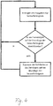
- FIG. 5 is a highly simplified flowchart showing the steps involved in carrying out the method described in detail above.
Abstract
Die vorliegende Erfindung betrifft eine Vorrichtung zum Steuern der Lichtfarbe des von einer Leuchte (L) abgegebenen Lichts. Die Vorrichtung weist einen Farbsensor (S), der ein Farbsignal von zumindest einem von der Leuchte (L1..L4) beleuchteten Zielobjekt (O) erzeugt, und eine Steuereinrichtung (5), die einem Farbwert des Farbsignals eine Lichtfarbe zuordnet und die Leuchte (L) auf der Grundlage der zugeordneten Lichtfarbe steuert, auf, wobei die Steuereinrichtung (5) dazu ausgelegt ist, die Anwesenheit eines Fremdobjekts (P) im Erfassungsbereich (E) des Farbsensors (S) auf der Grundlage einer Änderung des Farbsignals zu bestimmen und eine Änderung der Lichtfarbe zu unterdrücken, wenn die Anwesenheit eines Fremdobjekts (P) bestimmt wurde.The present invention relates to a device for controlling the light color of the light emitted by a lamp (L). The device has a color sensor (S) that generates a color signal from at least one target object (O) illuminated by the lamp (L1..L4), and a control device (5) that assigns a light color to a color value of the color signal and the lamp ( L) controls on the basis of the assigned light color, the control device (5) being designed to determine the presence of a foreign object (P) in the detection range (E) of the color sensor (S) on the basis of a change in the color signal and one Suppress change of light color when the presence of a foreign object (P) has been determined.
Description
Die vorliegende Erfindung betrifft eine Vorrichtung und ein Verfahren zum Steuern der Lichtfarbe des von einer Leuchte abgegebenen Lichts sowie ein Beleuchtungssystem mit einer solchen Vorrichtung. Die Erfindung betrifft insbesondere die automatische Anpassung der Lichtfarbe an einen Wechsel von zu beleuchtenden Objekten.The present invention relates to an apparatus and a method for controlling the light color of the light emitted by a luminaire and to a lighting system with such a device. In particular, the invention relates to the automatic adaptation of the light color to a change of objects to be illuminated.
Bei vielen Anwendungen hängt die Wahl der Lichtfarbe von dem zu beleuchtenden Objekt ab. So sollen die Farben von in Geschäften angebotenen Waren durch die Beleuchtung hervorgehoben werden, wobei bei Waren mit vermehrt roten Farben eine Beleuchtung mit einer warmen Lichtfarbe gewählt wird und bei Waren mit vielen Blautönen dagegen eine kalte Lichtfarbe bevorzugt wird.In many applications, the choice of light color depends on the object to be illuminated. Thus, the colors of goods offered in shops should be highlighted by the lighting, with goods with more red colors, a lighting is chosen with a warm light color and goods with many shades of blue contrast, a cold light color is preferred.
Mit Leuchten, welche eine stufenweise oder stufenlose Änderung der Lichtfarbe des von ihr abgegebenen Lichts erlauben, kann die Beleuchtung an ein neues Sortiment oder an eine neue Anordnung der Waren manuell oder automatisch angepasst werden.With lights that allow a gradual or continuous change in the light color of the light emitted by her, the lighting can be adapted to a new range or to a new arrangement of goods manually or automatically.
Die
Der Erfindung liegt die Aufgabe zugrunde, Vorrichtung und Verfahren anzugeben, die die beschriebenen Probleme verringern. Aufgabe ist es insbesondere, eine Vorrichtung und ein Verfahren zum Steuern der Lichtfarbe des von einer Leuchte abgegebenen Lichts sowie ein Beleuchtungssystem bereitzustellen, die in einfacher und günstiger Weise eine automatische Anpassung der Lichtfarbe an das zu beleuchtende Objekt erlauben.The invention has for its object to provide apparatus and methods that reduce the problems described. In particular, it is an object to provide an apparatus and a method for controlling the light color of the light emitted by a luminaire, as well as a lighting system which permit automatic adaptation of the light color to the object to be illuminated in a simple and favorable manner.
Diese Aufgabe wird gemäß den Merkmalen der unabhängigen Ansprüche gelöst. Die Erfindung wird durch die Merkmale der abhängigen Ansprüche weitergebildet.This object is achieved according to the features of the independent claims. The invention is further developed by the features of the dependent claims.
Gemäß der vorliegenden Erfindung weist die Vorrichtung zumindest einen Farbsensor und eine Steuereinrichtung auf, wobei der Farbsensor ein Farbsignal von zumindest einem von der Leuchte beleuchteten Zielobjekt erzeugt und die Steuereinrichtung einem Farbwert des Farbsignals eine Lichtfarbe zuordnet und die Leuchte auf der Grundlage der zugeordneten Lichtfarbe steuert. Die Steuereinrichtung ist dabei dazu ausgelegt, die Anwesenheit eines Fremdobjekts im Erfassungsbereich des Farbsensors auf der Grundlage einer Änderung des Farbsignals zu bestimmen und eine Änderung der Lichtfarbe zu unterdrücken, wenn die Anwesenheit eines Fremdobjekts bestimmt wurde.According to the present invention, the device has at least one color sensor and a control device, wherein the color sensor generates a color signal from at least one target object illuminated by the luminaire and the control device assigns a color of color to the color signal and controls the luminaire based on the assigned color of light. The control means is arranged to determine the presence of a foreign object in the detection range of the color sensor on the basis of a change in the color signal and to suppress a change in the light color when the presence of a foreign object has been determined.
Somit ist eine genaue Identifizierung des Zielobjekts nicht nötig. Die Lichtfarbe wird automatisch einerThus, a precise identification of the target object is not necessary. The light color automatically becomes one
Änderung der Farbe des Zielobjekts angepasst, wobei Farbänderungen von im Erfassungsbereich temporär befindlichen Fremdobjekten nicht berücksichtigt werden.Adjusting the color of the target object, ignoring color changes of foreign objects temporarily in the detection area.
Zielobjekte können in Regalen oder auf Tischen platzierte Waren und Fremdobjekte, Personen und/oder Einkaufswagen sein.Target objects may be shelves or goods placed on tables and foreign objects, persons and / or shopping carts.
Der Farbsensor kann ein kostengünstiger nicht-bildgebender Farbsensor sein.The color sensor may be a low cost non-imaging color sensor.
Farbänderungen von geringer Zeitdauer deuten auf sich im Erfassungsbereich temporär aufhaltende Personen und können unterdrückt bzw. herausgefiltert werden.Color changes of a short duration indicate temporary occupants in the detection area and can be suppressed or filtered out.
Alternativ oder zusätzlich können Farbänderungen, welche über eine längere Zeitdauer bestand haben und beispielsweise von in einem Regal oder auf einem Tisch neu positionierter Ware verursacht worden sind, bei der Steuerung bzw. Regelung der Lichtfarbe berücksichtigt werden. Hierzu kann die Steuereinrichtung bestimmen, ob für eine vorgegebene Zeitdauer keine weiteren Farbwertänderungen vorliegen oder die Farbwertänderungen während der Zeitdauer einen vorgegebenen Schwellenwert nicht übersteigen.Alternatively or additionally, color changes which have existed over a longer period of time and have been caused, for example, by goods repositioned on a shelf or on a table can be taken into account in the control or regulation of the light color. For this purpose, the control device can determine whether there are no further color value changes for a given period of time or the color value changes during the time duration do not exceed a predetermined threshold value.
Die Zeitdauer und/oder der Schwellenwert können vom Hersteller oder Nutzer eingegeben und gespeichert werden. Zusätzlich kann die Steuereinrichtung die Zeitdauer und/oder den Schwellenwert automatisch in Abhängigkeit von der Tageszeit und/oder dem Wochentag setzen.The duration and / or threshold may be entered and stored by the manufacturer or user. In addition, the controller may set the time duration and / or the threshold automatically depending on the time of day and / or the day of the week.
Die Genauigkeit der Filterung kann erhöht werden, wenn die individuelle Farbänderung, welche in dem Erfassungsbereich befindliche oder eintretende Fremdobjekte verursachen, bekannt ist. Diese von beispielsweise Personen mit und ohne Einkaufwagen verursachten Änderungen können für eine erneute Erfassung gespeichert und/oder an Vorrichtungen, die einen benachbarten Erfassungsbereich überwachen bzw. beleuchten, übermittelt werden.The accuracy of the filtering can be increased if the individual color change causing foreign objects located or entering the detection area is known. These changes caused by, for example, persons with and without shopping carts may be stored for re-acquisition and / or transmitted to devices that monitor or illuminate an adjacent coverage area.
Hierfür kann die Steuereinrichtung dazu ausgelegt sein, Fremdobjekte, wie Personen oder Personengruppen, mit unterschiedlichen Farben und/oder Farbmustern als Fremdobjekte auf der Grundlage des Farbsignals zu identifizieren, wobei einer Personen oder Personengruppe ein bestimmter Farbwert und/oder eine oder mehrere bestimmte Farbwertänderungen zugeordnet sind.For this purpose, the control device can be designed to identify foreign objects, such as persons or groups of people, with different colors and / or color patterns as foreign objects on the basis of the color signal, wherein a person or group of persons is assigned a specific color value and / or one or more specific color value changes ,
Die Genauigkeit der Filterung kann weiter erhöht werden, wenn die Bewegung der Fremdobjekte bezüglich der Erfassungsbereiche erkannt oder vorhergesagt wird. Die Vorrichtung kann hierfür zumindest einen zweiten Farbsensor oder eine Einrichtung zum Empfangen eines von einem zweiten Farbsensor erzeugten Farbsignals aufweisen, wobei der Erfassungsbereich des ersten Farbsensors und der Erfassungsbereich des zweiten Farbsensors zumindest teilweise unterschiedlich sind und die Steuereinrichtung dazu ausgelegt ist, die Bewegung einer Person oder Personengruppe auf der Grundlage des zeitlichen Auftretens eines Farbwerts und/oder einer Farbwertänderung in den Erfassungsbereichen zu ermitteln.The accuracy of the filtering can be further increased if the movement of the foreign objects with respect to the detection areas is detected or predicted. For this purpose, the device can have at least one second color sensor or a device for receiving a color signal generated by a second color sensor, wherein the detection range of the first color sensor and the detection range of the second color sensor are at least partially different and the control device is designed to monitor the movement of a person or Identify a person group on the basis of the temporal occurrence of a color value and / or a color value change in the detection areas.
Zusätzlich kann die Steuereinrichtung dazu ausgelegt sein, jeder identifizierten Person oder Personengruppe einen eindeutigen Namen zuzuordnen.In addition, the control device can be designed to assign a unique name to each identified person or group of persons.
Ein Beleuchtungssystem gemäß der vorliegenden Erfindung besteht aus zumindest zwei Leuchten, wobei jede Leuchte eine der oben beschriebenen Vorrichtungen zum Steuern der Lichtfarbe des von der Leuchte abgegebenen Lichts aufweist und die Steuereinrichtung der einen Leuchte dazu ausgelegt ist, den Namen und/oder eine Information zur Identifikation der dem Namen zugeordneten Person bzw. Personengruppe an die andere Leuchte zu übermitteln.An illumination system according to the present invention consists of at least two lights, each light having one of the above-described devices for controlling the light color of the light emitted by the light and the control device of a light is adapted to the name and / or information for identification to assign the person or group of persons assigned to the name to the other lamp.
Die Identifikationsinformation kann den Farbwert und/oder die Farbwertänderungen anzeigen, wobei jede Leuchte dazu ausgelegt ist:
- den übermittelten Namen und die übermittelte Identifikationsinformation zu speichern,
- bei einer Identifizierung einer Person bzw. Personengruppe im Erfassungsbereich auf der Grundlage der gespeicherten Identifikationsinformation zu bestimmen, ob der Person bzw. Personengruppe bereits ein Name zugeordnet ist,
- der Person bzw. Personengruppe einen eindeutigen Namen zuzuordnen und diesen zusammen mit der Identifikationsinformation an die andere Leuchte (S1..S4) zu übermitteln, wenn der Person noch kein Name zugeordnet ist, und
- den bereits zugeordneten bzw. den neuen Namen an die Ermittlungseinrichtung zu übermitteln.
- store the transmitted name and the transmitted identification information,
- determine whether an individual or group of persons has already been assigned a name in the case of an identification of a person or group of persons in the area of coverage on the basis of the stored identification information;
- to assign a unique name to the person or group of persons and to transmit this together with the identification information to the other lamp (S1..S4) if the person has not yet been assigned a name, and
- to transmit the already assigned or the new name to the determination device.
Gemäß der vorliegenden Erfindung weist ein Verfahren zum Steuern der Lichtfarbe des von zumindest einer Leuchte abgegebenen Lichts die Schritte:
- Erzeugen eines Farbsignals mit einem Farbsensor von zumindest einem von der Leuchte beleuchteten Zielobjekt,
- Zuordnen einer Zielobjekt-Lichtfarbe zu einem von dem Farbsignal angezeigten Farbwert, und
- Steuern der Lichtfarbe des von der Leuchte abgegebenen Lichts auf der Grundlage der Zielobjekt-Lichtfarbe auf, wobei eine Änderung der Lichtfarbe unterdrückt wird bzw. nicht erfolgt, wenn die Anwesenheit eines Fremdobjekts im Erfassungsbereich des Farbsensors auf der Grundlage einer Änderung des Farbsignals ermittelt wird.
- Generating a color signal with a color sensor from at least one target object illuminated by the luminaire,
- Assigning a target light color to a color value displayed by the color signal, and
- Controlling the light color of the light emitted from the lamp on the basis of the target light color, wherein a change of the light color is suppressed or not, when the presence of a foreign object in the detection range of the color sensor is determined on the basis of a change of the color signal.
Nachfolgend wird die Erfindung anhand der beiliegenden Zeichnungen näher erläutert. Es zeigen:
-
Fig. 1 eine Leuchte nach einem Ausführungsbeispiel gemäß der vorliegenden Erfindung, -
Fig. 2 ein Beleuchtungssystem nach einem Ausführungsbeispiel gemäß der vorliegenden Erfindung, -
Fig. 3 eine Steuerungsvorrichtung nach einem Ausführungsbeispiel gemäß der vorliegenden Erfindung, und -
Fig. 4 ein vereinfachtes Diagramm zur Darstellung des Verfahrens.
-
Fig. 1 a luminaire according to an embodiment according to the present invention, -
Fig. 2 an illumination system according to an embodiment according to the present invention, -
Fig. 3 a control device according to an embodiment of the present invention, and -
Fig. 4 a simplified diagram illustrating the method.
Komponenten mit gleichen Funktionen sind in den Figuren mit gleichen Bezugszeichen gekennzeichnet.Components with the same functions are identified in the figures with the same reference numerals.
Der Farbsensor 1 ist in dem gezeigten Beispiel in der Leuchte L integriert und im Bereich des Lichtaustritts der Leuchte L so angeordnet, dass der Erfassungsbereich E des Farbsensors S sich mit dem Ausleuchtungsbereich der Leuchte deckt. Der Farbsensor S kann ein nicht-bildgebender Sensor sein, der seinen Erfassungsbereich E abtastet und ein entsprechendes Farbsignal, das einen momentanen Farbwert für die Farben Rot, Grün und Blau anzeigt, ausgibt. Der ausgegebene Farbwert hängt dabei von der Farbe oder dem Farbmuster des Objekts 0 und dessen im Erfassungsbereich E befindlichen Umgebung ab. Das Objekt 0 kann während der Bestimmung des Farbwerts von der Leuchte L angestrahlt werden. Bei heller Umgebung ist es jedoch auch möglich Farbmessungen bei ausgeschaltetem Licht durchzuführen, um die Lichtfarbe für das nächste Einschalten zu bestimmen.The color sensor 1 is integrated in the example shown in the light L and arranged in the region of the light emission of the light L so that the detection range E of the color sensor S coincides with the illumination range of the lamp. The color sensor S may be a non-imaging sensor which samples its detection area E and outputs a corresponding color signal indicative of a current color value for the colors red, green and blue. The output color value depends on the color or the color pattern of the object 0 and its surroundings in the detection area E. The object 0 can be illuminated during the determination of the color value of the light L. In a bright environment, however, it is also possible to perform color measurements with the light off to determine the light color for the next power up.
Gemäß der vorliegenden Erfindung wird die Lichtfarbe automatisch der Farbe des Objekts 0 angepasst, wobei ein Austausch des Objekts 0 durch ein Objekt 0 mit einer anderen Farbe oder einem anderen Farbmuster eine Änderung/Anpassung der Lichtfarbe bewirkt. Dagegen werden Farbänderungen, die Fremdobjekte hervorrufen, welche sich im Gegensatz zum Ziel-Objekt 0 meist nur kurzzeitig im Erfassungsbereich E aufhalten, herausgefiltert oder nicht berücksichtigt. Bei der Filterung werden hochfrequente, sich zeitlich schnell ändernde Farbwerte und/oder von einem erkannten Fremdobjekt verfälschte Farbwerte herausgefiltert.According to the present invention, the light color is automatically adjusted to the color of the object 0, wherein an exchange of the object 0 by an object 0 with a different color or a different color pattern causes a change / adjustment of the light color. In contrast, color changes that cause foreign objects that are in contrast to the target object 0 mostly only briefly in the detection area E, filtered out or not taken into account. During filtering, high-frequency, rapidly changing color values and / or color values falsified by a detected foreign object are filtered out.
Fremdobjekte können Personen sein, die jedes Mal, wenn sie sich im Erfassungsbereich E befinden oder in ihn eintreten einen bestimmten Farbwert und/oder eine bestimmte Farbänderung (Farbfolge und Dynamik) hervorrufen, mittels der sie wiedererkennbar sind. Dabei bewirken unterschiedlich farbige Fremdobjekte/Personen unterschiedliche Farbwerte bzw. Farbänderungen, was sie untereinander unterscheidbar und identifizierbar macht.Foreign objects can be persons who, each time they enter or enter the detection area E, produce a certain color value and / or a certain color change (color sequence and dynamics), by means of which they are recognizable. At the same time, differently colored foreign objects / persons cause different color values or color changes, which makes them distinguishable from each other and identifiable.
Eine Identifizierung mittels solcher Farbwerte/Farbänderungen erlaubt eine sichere Ermittlung der Anwesenheit von Fremdobjekten, selbst wenn diese sich über eine längere Zeitdauer in dem Erfassungsbereich E aufhalten und erlaubt eine Bestimmung oder Vorhersage der Bewegung von Fremdobjekten durch mehrere Erfassungs-/Beleuchtungsbereiche in einem Beleuchtungssystem.Identification by means of such color values / color changes allows a reliable detection of the presence of foreign objects, even if they are present in the detection area E for a longer period of time, and allows a determination or prediction of the movement of foreign objects through multiple detection / illumination areas in a lighting system.
In dem Beleuchtungssystem weist, wie in
Alternativ kann, wie in
Die Speichereinrichtung 4 speichert die Tabelle oder Formel, die jeder ermittelten Objektfarbe eine Lichtfarbe zuordnet. Der Farbsensor S tastet seinen Erfassungsbereich E1..E4 ab und gibt ein entsprechendes Farbsignal (Farbwert) an die Steuereinrichtung 3 aus, welche mittels der gespeicherten Tabelle bzw. Formel eine Ziel-Lichtfarbe bestimmt und entsprechende Steuersignale an die Leuchte L sendet. Zudem ermittelt die Steuereinrichtung 3 auf der Grundlage der Sensorsignale, ob sich ein Fremdobjekt in dem Erfassungsbereich E1..E4 befindet und unterdrückt eine Änderung/Anpassnug der Lichtfarbe, wenn die Anwesenheit eines Fremdobjekts bestimmt wurde. Für eine Erkennung eines Fremdobjekts analysiert die Steuereinrichtung 3 den zeitlichen Verlauf der Farbänderungen in dem von dem Farbsensor S ausgegebenen Farbsignal und bestimmt, ob der Farbwert innerhalb einer bestimmten Zeit wieder einen Farbwert annimmt, auf dessen Grundlage die aktuell gesetzte Lichtfarbe ermittelt wurde.The
Alternativ oder zusätzlich kann die Steuereinrichtung 3 die Abwesenheit eines Fremdobjekts bestimmen, wenn innerhalb einer vorgegebenen Zeitdauer keine Farbwertänderungen vorliegen oder die Farbwertänderungen während der Zeitdauer einen vorgegebenen Schwellenwert nicht übersteigen.Alternatively or additionally, the
Ein in einem Erfassungsbereich E1 bis E4 befindliches Fremdobjekt, das eine Farbe oder ein Farbmuster aufweist, das von dem Ziel-Objekt O1 bis 04 abweicht, bewirkt eine Änderung in dem von dem Farbsensor S ausgegebenen Signal. So verschiebt sich der Farbwert durch die andere Farbe bzw. das andere Farbmuster des Fremdobjekts. Mit einer Analyse der Verschiebung können dem Fremdobjekt eindeutige Farbinformationen zugeordnet werden, die anzeigen, wie sich der Farbwert in jedem Erfassungsbereich E1..E4 mit dem Fremdobjekt ändern würde, und mittels denen das Fremdobjekt in einem Erfassungsbereich E1..E4 eindeutig identifizierbar ist. Zusätzlich können Muster im Zeit- und/oder Frequenzbereich detektiert werden, welche das Fremdobjekt in einem Erfassungsbereich E1..E4 erzeugt.A foreign object in a detection area E1 to E4 having a color or a color pattern deviating from the target object O1 to 04 causes a change in the signal output from the color sensor S. Thus, the color value shifts through the other color or the other color pattern of the foreign object. With an analysis of the displacement, unique color information can be assigned to the foreign object, which indicate how the color value in each detection area E1..E4 would change with the foreign object, and by means of which the foreign object can be unambiguously identified in a detection area E1..E4. In addition, patterns in the time and / or frequency range can be detected, which generates the foreign object in a detection range E1..E4.
Diese Informationen können von der Steuereinrichtung 3 zur Identifizierung des Fremdobjekts in der Speichereinrichtung 4 gespeichert und über den Datenbus D an die anderen Steuervorrichtungen 1 bzw. die anderen Leuchten L gesendet werden, welche die Informationen speichern. Mit den gespeicherten Identifikationsinformationen ist das Fremdobjekt dann in jedem Erfassungsbereich E1..E4 identifizierbar. Die Erstellung von Identifikationsinformationen erfolgt für jedes in einem Erfassungsbereich E1..E4 erstmalig erkannte Fremdobjekt. Jedem gespeicherten/registriertem Fremdobjekt kann zudem ein eindeutiger Name zugeordnet werden.This information can be stored by the
In dem in
Bewegt sich das Fremdobjekt P weiter zum Erfassungsbereich E2, wird es dort an Hand der Identifikationsinformationen identifiziert, wobei über die Reihenfolge der Erfassungen in den Erfassungsbereichen E1 und E2 und die Zeiten der Erfassungen sowohl die Bewegungsrichtung als auch die Bewegungsgeschwindigkeit des Fremdobjekts P ermittelt werden kann. Diese Informationen können für eine Vorhersage der Anwesenheit des Fremdobjekts P in einem Erfassungsbereich E1 bis E4 und/oder von anderen Gebäudetechnikkomponenten genutzt werden. Alternativ oder zusätzlich können diese Daten zur Auswertung oder Weiterverarbeitung an eine mobile Einrichtung, wie ein Tablet oder Smartphone, kabelgebunden oder kabellos übertagen werden.If the foreign object P continues to move to the detection area E2, it is identified there by the identification information, whereby both the direction of movement and the speed of movement of the foreign object P can be determined by the order of the detections in the detection areas E1 and E2 and the times of the acquisitions. This information can be used to predict the presence of the foreign object P in a detection area E1 to E4 and / or other building services components. Alternatively or additionally, these data can be transmitted for evaluation or further processing to a mobile device, such as a tablet or smartphone, wired or wireless.
Die erstmalige Detektion von Fremdobjekten P kann im Normalbetrieb oder in einem Lernbetrieb erfolgen. Im Lernbetrieb bewegt sich ein Fremdobjekt P beispielsweise mehrmals durch einen Erfassungsbereich E1 bis E4, welches der Steuereinrichtung 3 bzw. der zentralen Steuereinrichtung 3 angezeigt wird. Diese erlernt und speichert dann das zu diesem Fremdobjekt P gehörende Muster der Farbänderung.The first detection of foreign objects P can be done in normal operation or in a learning mode. In learning mode, a foreign object P moves, for example, several times through a detection range E1 to E4, which is the
In
Claims (10)
Applications Claiming Priority (2)
| Application Number | Priority Date | Filing Date | Title |
|---|---|---|---|
| DE102017221671.9A DE102017221671A1 (en) | 2017-12-01 | 2017-12-01 | Motion detection of persons using color sensors |
| DE102018105706.7A DE102018105706A1 (en) | 2018-03-13 | 2018-03-13 | Automatic adjustment of the light color of luminaires |
Publications (2)
| Publication Number | Publication Date |
|---|---|
| EP3493652A1 true EP3493652A1 (en) | 2019-06-05 |
| EP3493652B1 EP3493652B1 (en) | 2020-07-08 |
Family
ID=64401987
Family Applications (1)
| Application Number | Title | Priority Date | Filing Date |
|---|---|---|---|
| EP18206390.9A Active EP3493652B1 (en) | 2017-12-01 | 2018-11-15 | Automatic adaptation of the light colour of lights |
Country Status (1)
| Country | Link |
|---|---|
| EP (1) | EP3493652B1 (en) |
Citations (4)
| Publication number | Priority date | Publication date | Assignee | Title |
|---|---|---|---|---|
| JP2009028491A (en) * | 2007-06-22 | 2009-02-12 | Panasonic Electric Works Co Ltd | Shelf lighting system and shelf unit lighting system |
| WO2014016730A2 (en) * | 2012-07-27 | 2014-01-30 | Koninklijke Philips N.V. | Color emphasis and preservation of objects using reflection spectra |
| DE102014104174A1 (en) * | 2014-03-26 | 2015-10-01 | Steinel Gmbh | Controlled lighting device |
| WO2015195645A1 (en) * | 2014-06-20 | 2015-12-23 | Rensselaer Polytechnic Institute | Occupancy sensing smart lighting system |
-
2018
- 2018-11-15 EP EP18206390.9A patent/EP3493652B1/en active Active
Patent Citations (4)
| Publication number | Priority date | Publication date | Assignee | Title |
|---|---|---|---|---|
| JP2009028491A (en) * | 2007-06-22 | 2009-02-12 | Panasonic Electric Works Co Ltd | Shelf lighting system and shelf unit lighting system |
| WO2014016730A2 (en) * | 2012-07-27 | 2014-01-30 | Koninklijke Philips N.V. | Color emphasis and preservation of objects using reflection spectra |
| DE102014104174A1 (en) * | 2014-03-26 | 2015-10-01 | Steinel Gmbh | Controlled lighting device |
| WO2015195645A1 (en) * | 2014-06-20 | 2015-12-23 | Rensselaer Polytechnic Institute | Occupancy sensing smart lighting system |
Also Published As
| Publication number | Publication date |
|---|---|
| EP3493652B1 (en) | 2020-07-08 |
Similar Documents
| Publication | Publication Date | Title |
|---|---|---|
| EP2783550B1 (en) | Configuration of operating devices for lighting means | |
| DE102005014953A1 (en) | Motor vehicle with a lighting device with variable illumination volume | |
| DE102008019191A1 (en) | Device and method for uniform illumination of a surgical field | |
| AT14353U1 (en) | Shelf lighting system and method for locating goods and managing price information | |
| DE102010032761A1 (en) | Method for controlling controller for lighting system, involves detecting position or state of motion of person by using depth sensor camera | |
| DE2425893A1 (en) | Guiding system directing people - compares entered and stored data to produce indicator control signals | |
| DE102016118486A1 (en) | LIGHTING CONTROL DEVICE, LIGHTING SYSTEM AND METHOD FOR CONTROLLING A LIGHTING DEVICE | |
| DE102018105706A1 (en) | Automatic adjustment of the light color of luminaires | |
| WO2014078881A2 (en) | Configuration of operating devices for illuminants | |
| EP3493652B1 (en) | Automatic adaptation of the light colour of lights | |
| EP1623943A1 (en) | Device and method for detecting a feature of a running material web | |
| EP2473008B1 (en) | Method and lighting device for lighting an object with multiple light sources | |
| WO2018091202A1 (en) | System and method for generating presence profiles for building management | |
| EP2779801B1 (en) | Lighting system and method for controlling a lighting system | |
| EP1567982B1 (en) | Method and device for compensating for shadows in digital images | |
| WO2019105891A1 (en) | Motion detection of objects by means of motion sensors | |
| WO2017211606A1 (en) | Presence detection by means of radio signals in a lighting system | |
| DE19842465A1 (en) | Constant light control method | |
| EP3261061A1 (en) | Access control method and system | |
| EP2966593A1 (en) | Image acquisition system for detecting an object | |
| DE102016110109A1 (en) | Lighting system, scheduling controller and lighting control method | |
| AT17525U1 (en) | Motion detection of people using color sensors | |
| DE102023123163A1 (en) | Illumination device and illumination method with distance measurement and display | |
| DE102012007085A1 (en) | Method for automatically selecting lighting situation, involves detecting object by detection device, where detected object is compared with objects stored in database, and objects stored in database are correlated with lighting situation | |
| EP4102939A1 (en) | Guided installation of a luminaire with camera-based sensor system |
Legal Events
| Date | Code | Title | Description |
|---|---|---|---|
| PUAI | Public reference made under article 153(3) epc to a published international application that has entered the european phase |
Free format text: ORIGINAL CODE: 0009012 |
|
| STAA | Information on the status of an ep patent application or granted ep patent |
Free format text: STATUS: THE APPLICATION HAS BEEN PUBLISHED |
|
| AK | Designated contracting states |
Kind code of ref document: A1 Designated state(s): AL AT BE BG CH CY CZ DE DK EE ES FI FR GB GR HR HU IE IS IT LI LT LU LV MC MK MT NL NO PL PT RO RS SE SI SK SM TR |
|
| AX | Request for extension of the european patent |
Extension state: BA ME |
|
| STAA | Information on the status of an ep patent application or granted ep patent |
Free format text: STATUS: REQUEST FOR EXAMINATION WAS MADE |
|
| 17P | Request for examination filed |
Effective date: 20191129 |
|
| RBV | Designated contracting states (corrected) |
Designated state(s): AL AT BE BG CH CY CZ DE DK EE ES FI FR GB GR HR HU IE IS IT LI LT LU LV MC MK MT NL NO PL PT RO RS SE SI SK SM TR |
|
| REG | Reference to a national code |
Ref country code: DE Ref legal event code: R079 Ref document number: 502018001856 Country of ref document: DE Free format text: PREVIOUS MAIN CLASS: H05B0033080000 Ipc: H05B0047100000 |
|
| GRAP | Despatch of communication of intention to grant a patent |
Free format text: ORIGINAL CODE: EPIDOSNIGR1 |
|
| STAA | Information on the status of an ep patent application or granted ep patent |
Free format text: STATUS: GRANT OF PATENT IS INTENDED |
|
| RIC1 | Information provided on ipc code assigned before grant |
Ipc: H05B 47/10 20200101AFI20200224BHEP |
|
| INTG | Intention to grant announced |
Effective date: 20200311 |
|
| GRAS | Grant fee paid |
Free format text: ORIGINAL CODE: EPIDOSNIGR3 |
|
| GRAA | (expected) grant |
Free format text: ORIGINAL CODE: 0009210 |
|
| STAA | Information on the status of an ep patent application or granted ep patent |
Free format text: STATUS: THE PATENT HAS BEEN GRANTED |
|
| AK | Designated contracting states |
Kind code of ref document: B1 Designated state(s): AL AT BE BG CH CY CZ DE DK EE ES FI FR GB GR HR HU IE IS IT LI LT LU LV MC MK MT NL NO PL PT RO RS SE SI SK SM TR |
|
| REG | Reference to a national code |
Ref country code: CH Ref legal event code: EP Ref country code: AT Ref legal event code: REF Ref document number: 1289910 Country of ref document: AT Kind code of ref document: T Effective date: 20200715 |
|
| REG | Reference to a national code |
Ref country code: DE Ref legal event code: R096 Ref document number: 502018001856 Country of ref document: DE |
|
| REG | Reference to a national code |
Ref country code: IE Ref legal event code: FG4D Free format text: LANGUAGE OF EP DOCUMENT: GERMAN |
|
| REG | Reference to a national code |
Ref country code: LT Ref legal event code: MG4D |
|
| REG | Reference to a national code |
Ref country code: NL Ref legal event code: MP Effective date: 20200708 |
|
| PG25 | Lapsed in a contracting state [announced via postgrant information from national office to epo] |
Ref country code: FI Free format text: LAPSE BECAUSE OF FAILURE TO SUBMIT A TRANSLATION OF THE DESCRIPTION OR TO PAY THE FEE WITHIN THE PRESCRIBED TIME-LIMIT Effective date: 20200708 Ref country code: HR Free format text: LAPSE BECAUSE OF FAILURE TO SUBMIT A TRANSLATION OF THE DESCRIPTION OR TO PAY THE FEE WITHIN THE PRESCRIBED TIME-LIMIT Effective date: 20200708 Ref country code: SE Free format text: LAPSE BECAUSE OF FAILURE TO SUBMIT A TRANSLATION OF THE DESCRIPTION OR TO PAY THE FEE WITHIN THE PRESCRIBED TIME-LIMIT Effective date: 20200708 Ref country code: ES Free format text: LAPSE BECAUSE OF FAILURE TO SUBMIT A TRANSLATION OF THE DESCRIPTION OR TO PAY THE FEE WITHIN THE PRESCRIBED TIME-LIMIT Effective date: 20200708 Ref country code: NO Free format text: LAPSE BECAUSE OF FAILURE TO SUBMIT A TRANSLATION OF THE DESCRIPTION OR TO PAY THE FEE WITHIN THE PRESCRIBED TIME-LIMIT Effective date: 20201008 Ref country code: GR Free format text: LAPSE BECAUSE OF FAILURE TO SUBMIT A TRANSLATION OF THE DESCRIPTION OR TO PAY THE FEE WITHIN THE PRESCRIBED TIME-LIMIT Effective date: 20201009 Ref country code: LT Free format text: LAPSE BECAUSE OF FAILURE TO SUBMIT A TRANSLATION OF THE DESCRIPTION OR TO PAY THE FEE WITHIN THE PRESCRIBED TIME-LIMIT Effective date: 20200708 Ref country code: BG Free format text: LAPSE BECAUSE OF FAILURE TO SUBMIT A TRANSLATION OF THE DESCRIPTION OR TO PAY THE FEE WITHIN THE PRESCRIBED TIME-LIMIT Effective date: 20201008 Ref country code: PT Free format text: LAPSE BECAUSE OF FAILURE TO SUBMIT A TRANSLATION OF THE DESCRIPTION OR TO PAY THE FEE WITHIN THE PRESCRIBED TIME-LIMIT Effective date: 20201109 |
|
| PG25 | Lapsed in a contracting state [announced via postgrant information from national office to epo] |
Ref country code: PL Free format text: LAPSE BECAUSE OF FAILURE TO SUBMIT A TRANSLATION OF THE DESCRIPTION OR TO PAY THE FEE WITHIN THE PRESCRIBED TIME-LIMIT Effective date: 20200708 Ref country code: LV Free format text: LAPSE BECAUSE OF FAILURE TO SUBMIT A TRANSLATION OF THE DESCRIPTION OR TO PAY THE FEE WITHIN THE PRESCRIBED TIME-LIMIT Effective date: 20200708 Ref country code: RS Free format text: LAPSE BECAUSE OF FAILURE TO SUBMIT A TRANSLATION OF THE DESCRIPTION OR TO PAY THE FEE WITHIN THE PRESCRIBED TIME-LIMIT Effective date: 20200708 Ref country code: IS Free format text: LAPSE BECAUSE OF FAILURE TO SUBMIT A TRANSLATION OF THE DESCRIPTION OR TO PAY THE FEE WITHIN THE PRESCRIBED TIME-LIMIT Effective date: 20201108 |
|
| PG25 | Lapsed in a contracting state [announced via postgrant information from national office to epo] |
Ref country code: NL Free format text: LAPSE BECAUSE OF FAILURE TO SUBMIT A TRANSLATION OF THE DESCRIPTION OR TO PAY THE FEE WITHIN THE PRESCRIBED TIME-LIMIT Effective date: 20200708 |
|
| REG | Reference to a national code |
Ref country code: DE Ref legal event code: R097 Ref document number: 502018001856 Country of ref document: DE |
|
| PG25 | Lapsed in a contracting state [announced via postgrant information from national office to epo] |
Ref country code: EE Free format text: LAPSE BECAUSE OF FAILURE TO SUBMIT A TRANSLATION OF THE DESCRIPTION OR TO PAY THE FEE WITHIN THE PRESCRIBED TIME-LIMIT Effective date: 20200708 Ref country code: RO Free format text: LAPSE BECAUSE OF FAILURE TO SUBMIT A TRANSLATION OF THE DESCRIPTION OR TO PAY THE FEE WITHIN THE PRESCRIBED TIME-LIMIT Effective date: 20200708 Ref country code: DK Free format text: LAPSE BECAUSE OF FAILURE TO SUBMIT A TRANSLATION OF THE DESCRIPTION OR TO PAY THE FEE WITHIN THE PRESCRIBED TIME-LIMIT Effective date: 20200708 Ref country code: CZ Free format text: LAPSE BECAUSE OF FAILURE TO SUBMIT A TRANSLATION OF THE DESCRIPTION OR TO PAY THE FEE WITHIN THE PRESCRIBED TIME-LIMIT Effective date: 20200708 Ref country code: IT Free format text: LAPSE BECAUSE OF FAILURE TO SUBMIT A TRANSLATION OF THE DESCRIPTION OR TO PAY THE FEE WITHIN THE PRESCRIBED TIME-LIMIT Effective date: 20200708 Ref country code: SM Free format text: LAPSE BECAUSE OF FAILURE TO SUBMIT A TRANSLATION OF THE DESCRIPTION OR TO PAY THE FEE WITHIN THE PRESCRIBED TIME-LIMIT Effective date: 20200708 |
|
| PLBE | No opposition filed within time limit |
Free format text: ORIGINAL CODE: 0009261 |
|
| STAA | Information on the status of an ep patent application or granted ep patent |
Free format text: STATUS: NO OPPOSITION FILED WITHIN TIME LIMIT |
|
| PG25 | Lapsed in a contracting state [announced via postgrant information from national office to epo] |
Ref country code: AL Free format text: LAPSE BECAUSE OF FAILURE TO SUBMIT A TRANSLATION OF THE DESCRIPTION OR TO PAY THE FEE WITHIN THE PRESCRIBED TIME-LIMIT Effective date: 20200708 |
|
| 26N | No opposition filed |
Effective date: 20210409 |
|
| PG25 | Lapsed in a contracting state [announced via postgrant information from national office to epo] |
Ref country code: SK Free format text: LAPSE BECAUSE OF FAILURE TO SUBMIT A TRANSLATION OF THE DESCRIPTION OR TO PAY THE FEE WITHIN THE PRESCRIBED TIME-LIMIT Effective date: 20200708 Ref country code: MC Free format text: LAPSE BECAUSE OF FAILURE TO SUBMIT A TRANSLATION OF THE DESCRIPTION OR TO PAY THE FEE WITHIN THE PRESCRIBED TIME-LIMIT Effective date: 20200708 |
|
| PG25 | Lapsed in a contracting state [announced via postgrant information from national office to epo] |
Ref country code: LU Free format text: LAPSE BECAUSE OF NON-PAYMENT OF DUE FEES Effective date: 20201115 |
|
| REG | Reference to a national code |
Ref country code: BE Ref legal event code: MM Effective date: 20201130 |
|
| PG25 | Lapsed in a contracting state [announced via postgrant information from national office to epo] |
Ref country code: SI Free format text: LAPSE BECAUSE OF FAILURE TO SUBMIT A TRANSLATION OF THE DESCRIPTION OR TO PAY THE FEE WITHIN THE PRESCRIBED TIME-LIMIT Effective date: 20200708 |
|
| PG25 | Lapsed in a contracting state [announced via postgrant information from national office to epo] |
Ref country code: IE Free format text: LAPSE BECAUSE OF NON-PAYMENT OF DUE FEES Effective date: 20201115 |
|
| PG25 | Lapsed in a contracting state [announced via postgrant information from national office to epo] |
Ref country code: TR Free format text: LAPSE BECAUSE OF FAILURE TO SUBMIT A TRANSLATION OF THE DESCRIPTION OR TO PAY THE FEE WITHIN THE PRESCRIBED TIME-LIMIT Effective date: 20200708 Ref country code: MT Free format text: LAPSE BECAUSE OF FAILURE TO SUBMIT A TRANSLATION OF THE DESCRIPTION OR TO PAY THE FEE WITHIN THE PRESCRIBED TIME-LIMIT Effective date: 20200708 Ref country code: CY Free format text: LAPSE BECAUSE OF FAILURE TO SUBMIT A TRANSLATION OF THE DESCRIPTION OR TO PAY THE FEE WITHIN THE PRESCRIBED TIME-LIMIT Effective date: 20200708 |
|
| PG25 | Lapsed in a contracting state [announced via postgrant information from national office to epo] |
Ref country code: MK Free format text: LAPSE BECAUSE OF FAILURE TO SUBMIT A TRANSLATION OF THE DESCRIPTION OR TO PAY THE FEE WITHIN THE PRESCRIBED TIME-LIMIT Effective date: 20200708 |
|
| PG25 | Lapsed in a contracting state [announced via postgrant information from national office to epo] |
Ref country code: BE Free format text: LAPSE BECAUSE OF NON-PAYMENT OF DUE FEES Effective date: 20201130 |
|
| P01 | Opt-out of the competence of the unified patent court (upc) registered |
Effective date: 20230530 |
|
| REG | Reference to a national code |
Ref country code: DE Ref legal event code: R084 Ref document number: 502018001856 Country of ref document: DE |
|
| PGFP | Annual fee paid to national office [announced via postgrant information from national office to epo] |
Ref country code: GB Payment date: 20231121 Year of fee payment: 6 |
|
| PGFP | Annual fee paid to national office [announced via postgrant information from national office to epo] |
Ref country code: FR Payment date: 20231123 Year of fee payment: 6 Ref country code: DE Payment date: 20231127 Year of fee payment: 6 Ref country code: CH Payment date: 20231202 Year of fee payment: 6 |