EP3493234A1 - Operating device and circuit breaker - Google Patents
Operating device and circuit breaker Download PDFInfo
- Publication number
- EP3493234A1 EP3493234A1 EP16911572.2A EP16911572A EP3493234A1 EP 3493234 A1 EP3493234 A1 EP 3493234A1 EP 16911572 A EP16911572 A EP 16911572A EP 3493234 A1 EP3493234 A1 EP 3493234A1
- Authority
- EP
- European Patent Office
- Prior art keywords
- torsion bar
- lever
- operating device
- rotation axis
- intermediate connecting
- Prior art date
- Legal status (The legal status is an assumption and is not a legal conclusion. Google has not performed a legal analysis and makes no representation as to the accuracy of the status listed.)
- Granted
Links
Images



Classifications
-
- H—ELECTRICITY
- H01—ELECTRIC ELEMENTS
- H01H—ELECTRIC SWITCHES; RELAYS; SELECTORS; EMERGENCY PROTECTIVE DEVICES
- H01H3/00—Mechanisms for operating contacts
- H01H3/22—Power arrangements internal to the switch for operating the driving mechanism
- H01H3/30—Power arrangements internal to the switch for operating the driving mechanism using spring motor
- H01H3/3042—Power arrangements internal to the switch for operating the driving mechanism using spring motor using a torsion spring
-
- H—ELECTRICITY
- H01—ELECTRIC ELEMENTS
- H01H—ELECTRIC SWITCHES; RELAYS; SELECTORS; EMERGENCY PROTECTIVE DEVICES
- H01H3/00—Mechanisms for operating contacts
- H01H3/22—Power arrangements internal to the switch for operating the driving mechanism
- H01H3/30—Power arrangements internal to the switch for operating the driving mechanism using spring motor
-
- H—ELECTRICITY
- H01—ELECTRIC ELEMENTS
- H01H—ELECTRIC SWITCHES; RELAYS; SELECTORS; EMERGENCY PROTECTIVE DEVICES
- H01H33/00—High-tension or heavy-current switches with arc-extinguishing or arc-preventing means
- H01H33/02—Details
- H01H33/28—Power arrangements internal to the switch for operating the driving mechanism
- H01H33/40—Power arrangements internal to the switch for operating the driving mechanism using spring motor
-
- H—ELECTRICITY
- H01—ELECTRIC ELEMENTS
- H01H—ELECTRIC SWITCHES; RELAYS; SELECTORS; EMERGENCY PROTECTIVE DEVICES
- H01H33/00—High-tension or heavy-current switches with arc-extinguishing or arc-preventing means
- H01H33/02—Details
- H01H33/42—Driving mechanisms
Definitions
- the present invention relates to an operating device that opens and closes a contact by using energy stored by torsion of a torsion bar and a circuit breaker including the operating device.
- an operating device that opens and closes a contact of a circuit breaker installed in a substation or a switching station includes a torsion bar, as disclosed in Patent Literature 1.
- opening and closing operation of the contact is performed by using energy stored by torsion applied to the torsion bar.
- Patent Literature 1 Japanese Patent Application Laid-Open No. S63-304542
- the circuit breaker has a tank containing the contact inside and a sealed insulating gas, and the operating device is attached to an end surface of the tank. Also, since a lever of the operating device is connected to the contact, the operating device is generally provided so that the lever is located on the end surface of the tank. In the above conventional operating device, an amount of protrusion of the torsion bar out of the tank is increased, resulting in problems of increasing a size of the circuit breaker and complicating a structure due to addition of a support structure for supporting the torsion bar.
- the device when the operating device is attached to a three-phase separation type circuit breaker in which three-phase circuits are housed in separate tanks, the device tends to become larger to secure a space for the torsion bar protruding from the operating device attached to each of the tanks.
- the present invention has been made in view of the above, and an object thereof is to obtain an operating device that can contribute to miniaturization of a circuit breaker and simplification of a structure.
- an operating device includes: a first lever rotatable around a rotation axis; a torsion bar having a columnar shape or a tubular shape with the rotation axis as a central axis and connected to the first lever; and a support that fixes and supports one end of the torsion bar.
- the operating device includes: a drive shaft having a tubular shape with the rotation axis as a central axis and surrounding a periphery of the torsion bar, one end serving as the first lever side being connected to the first lever, and another end opposite to the one end serving as the first lever side being rotatably supported around the rotation axis; and a plurality of second levers connected to the drive shaft and rotatable around the rotation axis on the support side rather than the first lever.
- FIG. 1 is a plan view of a circuit breaker according to a first embodiment of the present invention.
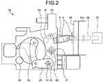
- FIG. 2 is a side view of a circuit breaker 50 according to the first embodiment as viewed along an arrow A.
- FIG. 3 is a cross-sectional view taken along a line B-B illustrated in FIG. 1 .
- the circuit breaker 50 includes three tanks 51a to 51c in which an insulating gas is sealed.
- the three tanks 51a to 51c are disposed linearly as illustrated in FIG. 1 .
- An operating device 52 is attached to an end surface 49 which is a top face of the tank 51a provided at an end.
- the operating device 52 includes a housing 53 fixed to the end surface 49 of the tank 51 via a mounting seat 9, an opening torsion bar 1 extending from the housing 53 along a first direction indicated by an arrow X, a closing torsion bar 2 extending from the housing 53 along the direction indicated by the arrow X, and a support 14 provided so as to face the housing 53.
- FIG. 4 is a plan sectional view of the opening torsion bar 1 portion of the operating device 52 according to the first embodiment.
- a through hole 53a penetrating along the direction indicated by the arrow X is formed in the housing 53 of the operating device 52.
- an opening shaft 16 is supported so as to be rotatable around a rotation axis 60 via a bearing 18.
- the opening shaft 16 has a tubular shape with the rotation axis 60 as a central axis.
- An output lever 15 serving as a first lever is connected to the opening shaft 16.
- the output lever 15 is rotatable around the rotation axis 60 together with the opening shaft 16. Further, the output lever 15 is housed inside the housing 53.
- the output lever 15 is connected to a movable contact 56 via a link mechanism 4.
- the movable contact 56 is housed inside the tank 51a. As the output lever 15 rotates, the movable contact 56 moves. The movable contact 56 moves between a position where the movable contact 56 comes into contact with a fixed contact 57 provided in the tank 51a and a position where the movable contact 56 is separated from the fixed contact 57.
- the movable contact 56 and the fixed contact 57 constitute a circuit contact that can come into and out of contact with each other.
- the fixed contact 57 is also housed inside the tank 51a.
- the circuit contact having the movable contact 56 and the fixed contact 57 is also provided inside the tank 51b and inside the tank 51c.
- the circuit breaker 50 is a three-phase separation type circuit breaker in which a circuit contact is provided inside each of the tanks 51a to 51c. It should be noted that a so-called three-phase batch type circuit breaker in which three circuit contacts are housed in one tank may be used.
- a torsion bar 12 is connected to the opening shaft 16. Specifically, the opening shaft 16 and the torsion bar 12 are connected by a contact part 17 where an inner peripheral surface of the opening shaft 16 and an outer peripheral surface of the torsion bar 12 are in contact. In this configuration, it can be said that the output lever 15 and the torsion bar 12 are connected via the opening shaft 16.
- the torsion bar 12 has a columnar shape extending from the opening shaft 16 in the direction indicated by the arrow X with the rotation axis 60 as a central axis. Further, an end on the support 14 side of the torsion bar 12 is fixed to and supported by the support 14. Specifically, the end on the support 14 side of the torsion bar 12 is inserted into a recess formed in the support 14 and is connected to the support 14 by a contact part 21 where the torsion bar 12 and the support 14 contact each other.
- a drive shaft 3 is connected to the opening shaft 16 on the support 14 side rather than the output lever 15.
- the drive shaft 3 has a tubular shape centered on the rotation axis 60.
- the drive shaft 3 and the opening shaft 16 are connected by a contact part 19 where an inner peripheral surface of the drive shaft 3 and an outer peripheral surface of the opening shaft 16 are in contact.
- the contact parts 17, 19, and 21 described above may have, for example, hexagonal or serration shapes that are engaged with each other, or may be joined by welding or the like.
- the drive shaft 3 is rotatably supported on the torsion bar 12 at the end on the support 14 side via a bearing 20. As a result, in the drive shaft 3, the entire drive shaft 3 rotates in synchronization with the rotation of the output lever 15.
- the torsion bar 12 is longer than the drive shaft 3, and the end of the torsion bar 12 protrudes from the drive shaft 3.
- Two interlocking levers 6 serving as second levers are connected to the drive shaft 3 on the support 14 side rather than the output lever 15.
- the interlocking lever 6 rotates in synchronization with the rotation of the drive shaft 3.
- the interlocking lever 6 rotates in synchronization with the rotation of the output lever 15.
- the interlocking lever 6 is connected to each of the tanks 51b and 51c via a link mechanism 5. As the interlocking lever 6 rotates in synchronization with the rotation of the output lever 15, the movable contact 56 in each of the tanks 51b and 51c moves between a position where the movable contact 56 comes into contact with the fixed contact 57 and a position where the movable contact 56 is separated from the fixed contact 57.
- the torsion bar 12 In the opening torsion bar 1 of the operating device 52, when the output lever 15 on a free end side rotates around the rotation axis 60, the torsion bar 12 is twisted, and energy that tries to return to an original state is stored. In the operating device 52, in a state in which the torsion bar 12 is twisted, the movable contact 56 and the fixed contact 57 come into contact in the tank 51a. In addition, by returning the torsion bar 12 from the twisted state to the original state, the movable contact 56 is separated from the fixed contact 57 in the tank 51a.
- the torsion bar 12 By restricting the return of the torsion bar 12 from the twisted state to the original state by a latch mechanism being not illustrated, it is possible to maintain a state in which the movable contact 56 and the fixed contact 57 are in contact with each other in the tank 51a.
- the torsion bar 12 returns from the twisted state to the original state, and the movable contact 56 can be separated from the fixed contact 57 in the tank 51a.
- the movable contact 56 can be moved at a high speed and separated from the fixed contact 57.
- the interlocking lever 6 since the interlocking lever 6 is connected to the drive shaft 3 rotating synchronously with the rotation of the output lever 15, the interlocking lever 6 also rotates in synchronization with the rotation of the output lever 15. Since contact and separation of the movable contact 56 and the fixed contact 57 are switched also within each of the tanks 51b and 51c by the rotation of the interlocking lever 6, the contact and separation of the movable contact 56 and the fixed contact 57 in the tanks 51a to 51c can be switched all at once by the rotation of the output lever. In other words, in one operating device 52, the contact and separation of the movable contact 56 and the fixed contact 57 in the three tanks 51a to 51c can be switched all at once.
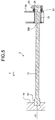
- FIG. 5 is a plan sectional view of the closing torsion bar 2 portion of the operating device 52 according to the first embodiment.
- a through hole 53b penetrating along the direction indicated by the arrow X is formed in the housing 53 of the operating device 52.
- a closing shaft 22 is rotatably supported around a rotation axis 61 via a bearing 23 in the through hole 53b.
- the closing shaft 22 has a tubular shape with the rotation axis 61 as a central axis.
- a closing lever 25 is connected to the closing shaft 22.
- the closing lever 25 is rotatable around the rotation axis 61 together with the opening shaft 22.
- a torsion bar 13 is connected to the closing shaft 22. Specifically, the closing shaft 22 and the torsion bar 13 are connected by a contact part 24 where an inner peripheral surface of the closing shaft 22 and an outer peripheral surface of the torsion bar 13 are in contact. In this configuration, it can be said that the closing lever 25 and the torsion bar 13 are connected via the closing shaft 22.
- the torsion bar 13 has a columnar shape extending from the closing shaft 22 in the direction indicated by the arrow X with the rotation axis 61 as a central axis. Further, an end on the support 14 side of the torsion bar 13 is fixed to and supported by the support 14. Specifically, the end on the support 14 side of the torsion bar 13 is inserted into a recess formed in the support 14 and is connected to the support 14 by a contact part 26 where the torsion bar 13 and the support 14 contact each other.
- the above-described contact parts 24 and 26 may have, for example, hexagonal or serration shapes that are engaged with each other, or may be joined by welding or the like.
- the torsion bar 13 returns from the twisted state to the original state, and the cam 54 rotates the output lever 15, whereby the movable contact 56 can make contact with the fixed contact 57.
- the movable contact 56 can be moved at a high speed to make contact with the fixed contact 57.
- the output lever 15 pressed by the cam 54 rotates, the torsion bar 12 is twisted and energy is stored in the torsion bar 12.
- the state in which the movable contact 56 is in contact with the fixed contact 57 can be maintained. Thereafter, by applying torsion to the torsion bar 13 by an electric motor 62, it is possible to move the cam 54 and store energy in the torsion bar 13.
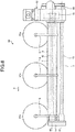
- FIG. 6 is a plan view of a circuit breaker according to a first modification of the first embodiment.
- the movable contacts 56 housed in the three tanks 51a to 51c are operated by the three interlocking levers 6 serving as second levers connected to the drive shaft 3. Therefore, in the first modification, a link mechanism is not connected to the output lever 15.
- a configuration in which the output lever 15 and the movable contact 56 are not directly connected is adopted, it is possible to switch opening and closing of three-phase circuit contacts by the one operating device 52. Therefore, it is possible to downsize the circuit breaker 50 and simplify the structure as compared with the case where the operating device is provided for each phase.
- the configuration in the first modification is advantageous in arranging a torsion bar when an overall length of the torsion bar is increased due to requirement of a high output for an operating device.
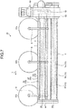
- FIG. 7 is a plan view of a circuit breaker according to a second modification of the first embodiment.
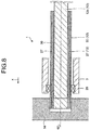
- FIG. 8 is a view schematically illustrating a structure of the opening torsion bar 1 of the circuit breaker according to the second modification of the first embodiment.
- the torsion bar 12 includes an even number of intermediate connecting bars 27 and 30 having cylindrical shapes and provided concentrically around the rotation axis 60 and a center bar 12c provided inside the intermediate connecting bars 27 and 30.
- FIGS. 7 and 8 each illustrate an example in which the two intermediate connecting bars 27 and 30 are provided.
- the center bar 12c has the same configuration as the configuration of the torsion bar 12 illustrated in FIG. 4 except that the center bar 12c is not directly fixed to the support 14.
- the intermediate connecting bars 27 and 30 have concentric cylindrical shapes centered on the rotation axis 61.
- the odd-numbered intermediate connecting bar 27 counted from the center bar 12c side, that is, from inside, is connected to the center bar 12c or the intermediate connecting bar provided inside on one end side on the support 14 side.
- the even-numbered intermediate connecting bar 30 counted from the center bar 12c side, that is, from the inside is connected to the intermediate connecting bar 27 provided inside on another end side which is the housing 53 side.
- the intermediate connecting bar 30 provided on an outermost side is fixed to and supported by the support 14. Further, in other words, in the intermediate connecting bar 27, a connecting part with the bar provided inside and a connecting part provided outside are spaced apart in a direction along the rotation axis 60. Note that the drive shaft 3 is rotatably supported via the bearing 20 with respect to the intermediate connecting bar 30 provided on the outermost side.
- the torsion bar 12 is configured to have a plurality of folds, a length of a twisted portion when the output lever 15 rotates can be increased. Thereby, restoring force from torsion of the torsion bar 12 can be increased. Therefore, it is possible to further speed up operation of the movable contact 56. This makes it possible to apply the operating device 52 to a circuit breaker handling a large current that requires high speed operation.
- the intermediate connecting bar 30 provided outside is formed to be thinner than the intermediate connecting bar 27 provided inside. This is because a cross-sectional area for obtaining necessary restoring force is determined in the intermediate connecting bars 27 and 30, and when the intermediate connecting bars 27 and 30 are formed by the cross-sectional area thereof, the intermediate connecting bar 30 disposed outside can be made thinner.
- the torsion bar 13 may include intermediate connecting bars 57 and 58 and a center bar 13c.
- the torsion bar 13 may include intermediate connecting bars 57 and 58 and a center bar 13c.
- the three interlocking levers 6 are used is illustrated, but as in the example illustrated in FIGS. 1 , 2 , and 4 , it may be configured to use the two interlocking levers 6 by connecting the output lever 15 of the operating device 52 with the movable contact 56 in the tank 51a via the link mechanism 4.
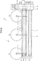
- FIG. 9 is a plan view of the circuit breaker 50 according to a third modification of the first embodiment.
- the torsion bar 12 has a tubular shape with the rotation axis 60 as a central axis
- the torsion bar 13 has a tubular shape with the rotation axis 61 as a center. Note that, for ease of understanding of the drawing, the torsion bar 12 and the torsion bar 13 are hatched.
Landscapes
- Driving Mechanisms And Operating Circuits Of Arc-Extinguishing High-Tension Switches (AREA)
Abstract
Description
- The present invention relates to an operating device that opens and closes a contact by using energy stored by torsion of a torsion bar and a circuit breaker including the operating device.
- It is known that an operating device that opens and closes a contact of a circuit breaker installed in a substation or a switching station includes a torsion bar, as disclosed in
Patent Literature 1. In such an operating device, opening and closing operation of the contact is performed by using energy stored by torsion applied to the torsion bar. - Patent Literature 1: Japanese Patent Application Laid-Open No.
S63-304542 - The circuit breaker has a tank containing the contact inside and a sealed insulating gas, and the operating device is attached to an end surface of the tank. Also, since a lever of the operating device is connected to the contact, the operating device is generally provided so that the lever is located on the end surface of the tank. In the above conventional operating device, an amount of protrusion of the torsion bar out of the tank is increased, resulting in problems of increasing a size of the circuit breaker and complicating a structure due to addition of a support structure for supporting the torsion bar. Particularly, when the operating device is attached to a three-phase separation type circuit breaker in which three-phase circuits are housed in separate tanks, the device tends to become larger to secure a space for the torsion bar protruding from the operating device attached to each of the tanks.
- The present invention has been made in view of the above, and an object thereof is to obtain an operating device that can contribute to miniaturization of a circuit breaker and simplification of a structure.
- In order to solve the above-mentioned problems and achieve the object, an operating device includes: a first lever rotatable around a rotation axis; a torsion bar having a columnar shape or a tubular shape with the rotation axis as a central axis and connected to the first lever; and a support that fixes and supports one end of the torsion bar. In addition, the operating device includes: a drive shaft having a tubular shape with the rotation axis as a central axis and surrounding a periphery of the torsion bar, one end serving as the first lever side being connected to the first lever, and another end opposite to the one end serving as the first lever side being rotatably supported around the rotation axis; and a plurality of second levers connected to the drive shaft and rotatable around the rotation axis on the support side rather than the first lever.
- According to the present invention, it is possible to obtain an operating device which can contribute to miniaturization of a circuit breaker and simplification of a structure.
-
-
FIG. 1 is a plan view of a circuit breaker according to a first embodiment of the present invention. -
FIG. 2 is a side view of the circuit breaker according to the first embodiment as seen along an arrow A. -
FIG. 3 is a cross-sectional view taken along a line B-B illustrated inFIG. 1 . -
FIG. 4 is a plan sectional view of an opening torsion bar portion of an operating device according to the first embodiment. -
FIG. 5 is a plan sectional view of a closing torsion bar portion of the operating device according to the first embodiment. -
FIG. 6 is a plan view of a circuit breaker according to a first modification of the first embodiment. -
FIG. 7 is a plan view of a circuit breaker according to a second modification of the first embodiment. -
FIG. 8 is a view schematically illustrating a structure of an opening torsion bar of the circuit breaker according to the second modification of the first embodiment. -
FIG. 9 is a plan view of a circuit breaker according to a third modification of the first embodiment. - Hereinafter, an operating device and a circuit breaker according to an embodiment of the present invention will be described in detail with reference to the drawings. It should be noted that the present invention is not limited by this embodiment.
-
FIG. 1 is a plan view of a circuit breaker according to a first embodiment of the present invention.FIG. 2 is a side view of acircuit breaker 50 according to the first embodiment as viewed along an arrow A.FIG. 3 is a cross-sectional view taken along a line B-B illustrated inFIG. 1 . - The
circuit breaker 50 includes threetanks 51a to 51c in which an insulating gas is sealed. The threetanks 51a to 51c are disposed linearly as illustrated inFIG. 1 . Anoperating device 52 is attached to anend surface 49 which is a top face of thetank 51a provided at an end. - The
operating device 52 includes ahousing 53 fixed to theend surface 49 of the tank 51 via amounting seat 9, anopening torsion bar 1 extending from thehousing 53 along a first direction indicated by an arrow X, aclosing torsion bar 2 extending from thehousing 53 along the direction indicated by the arrow X, and asupport 14 provided so as to face thehousing 53. -
FIG. 4 is a plan sectional view of theopening torsion bar 1 portion of theoperating device 52 according to the first embodiment. A throughhole 53a penetrating along the direction indicated by the arrow X is formed in thehousing 53 of theoperating device 52. In thethrough hole 53a, anopening shaft 16 is supported so as to be rotatable around arotation axis 60 via abearing 18. Theopening shaft 16 has a tubular shape with therotation axis 60 as a central axis. - An
output lever 15 serving as a first lever is connected to theopening shaft 16. Theoutput lever 15 is rotatable around therotation axis 60 together with theopening shaft 16. Further, theoutput lever 15 is housed inside thehousing 53. As illustrated inFIG. 2 , theoutput lever 15 is connected to amovable contact 56 via alink mechanism 4. Themovable contact 56 is housed inside thetank 51a. As the output lever 15 rotates, themovable contact 56 moves. Themovable contact 56 moves between a position where themovable contact 56 comes into contact with a fixedcontact 57 provided in thetank 51a and a position where themovable contact 56 is separated from the fixedcontact 57. Themovable contact 56 and the fixedcontact 57 constitute a circuit contact that can come into and out of contact with each other. Note that the fixedcontact 57 is also housed inside thetank 51a. Further, the circuit contact having themovable contact 56 and the fixedcontact 57 is also provided inside thetank 51b and inside thetank 51c. Thecircuit breaker 50 is a three-phase separation type circuit breaker in which a circuit contact is provided inside each of thetanks 51a to 51c. It should be noted that a so-called three-phase batch type circuit breaker in which three circuit contacts are housed in one tank may be used. - A
torsion bar 12 is connected to theopening shaft 16. Specifically, theopening shaft 16 and thetorsion bar 12 are connected by acontact part 17 where an inner peripheral surface of theopening shaft 16 and an outer peripheral surface of thetorsion bar 12 are in contact. In this configuration, it can be said that theoutput lever 15 and thetorsion bar 12 are connected via theopening shaft 16. - The
torsion bar 12 has a columnar shape extending from theopening shaft 16 in the direction indicated by the arrow X with therotation axis 60 as a central axis. Further, an end on thesupport 14 side of thetorsion bar 12 is fixed to and supported by thesupport 14. Specifically, the end on thesupport 14 side of thetorsion bar 12 is inserted into a recess formed in thesupport 14 and is connected to thesupport 14 by acontact part 21 where thetorsion bar 12 and thesupport 14 contact each other. - A
drive shaft 3 is connected to theopening shaft 16 on thesupport 14 side rather than theoutput lever 15. Thedrive shaft 3 has a tubular shape centered on therotation axis 60. Thedrive shaft 3 and theopening shaft 16 are connected by acontact part 19 where an inner peripheral surface of thedrive shaft 3 and an outer peripheral surface of theopening shaft 16 are in contact. Thecontact parts - The
drive shaft 3 is rotatably supported on thetorsion bar 12 at the end on thesupport 14 side via abearing 20. As a result, in thedrive shaft 3, theentire drive shaft 3 rotates in synchronization with the rotation of theoutput lever 15. Thetorsion bar 12 is longer than thedrive shaft 3, and the end of thetorsion bar 12 protrudes from thedrive shaft 3. - Two interlocking
levers 6 serving as second levers are connected to thedrive shaft 3 on thesupport 14 side rather than theoutput lever 15. The interlockinglever 6 rotates in synchronization with the rotation of thedrive shaft 3. As a result, the interlockinglever 6 rotates in synchronization with the rotation of theoutput lever 15. - As illustrated in
FIG. 3 , the interlockinglever 6 is connected to each of thetanks link mechanism 5. As the interlockinglever 6 rotates in synchronization with the rotation of theoutput lever 15, themovable contact 56 in each of thetanks movable contact 56 comes into contact with the fixedcontact 57 and a position where themovable contact 56 is separated from the fixedcontact 57. - In the
opening torsion bar 1 of the operatingdevice 52, when theoutput lever 15 on a free end side rotates around therotation axis 60, thetorsion bar 12 is twisted, and energy that tries to return to an original state is stored. In the operatingdevice 52, in a state in which thetorsion bar 12 is twisted, themovable contact 56 and the fixedcontact 57 come into contact in thetank 51a. In addition, by returning thetorsion bar 12 from the twisted state to the original state, themovable contact 56 is separated from the fixedcontact 57 in thetank 51a. By restricting the return of thetorsion bar 12 from the twisted state to the original state by a latch mechanism being not illustrated, it is possible to maintain a state in which themovable contact 56 and the fixedcontact 57 are in contact with each other in thetank 51a. In addition, by releasing restriction of the return by the latch mechanism, thetorsion bar 12 returns from the twisted state to the original state, and themovable contact 56 can be separated from the fixedcontact 57 in thetank 51a. In other words, by utilizing the energy stored by the torsion, themovable contact 56 can be moved at a high speed and separated from the fixedcontact 57. At this time, since the interlockinglever 6 is connected to thedrive shaft 3 rotating synchronously with the rotation of theoutput lever 15, the interlockinglever 6 also rotates in synchronization with the rotation of theoutput lever 15. Since contact and separation of themovable contact 56 and the fixedcontact 57 are switched also within each of thetanks lever 6, the contact and separation of themovable contact 56 and the fixedcontact 57 in thetanks 51a to 51c can be switched all at once by the rotation of the output lever. In other words, in oneoperating device 52, the contact and separation of themovable contact 56 and the fixedcontact 57 in the threetanks 51a to 51c can be switched all at once. -
FIG. 5 is a plan sectional view of the closingtorsion bar 2 portion of the operatingdevice 52 according to the first embodiment. A throughhole 53b penetrating along the direction indicated by the arrow X is formed in thehousing 53 of the operatingdevice 52. A closingshaft 22 is rotatably supported around arotation axis 61 via abearing 23 in the throughhole 53b. The closingshaft 22 has a tubular shape with therotation axis 61 as a central axis. - A closing
lever 25 is connected to the closingshaft 22. The closinglever 25 is rotatable around therotation axis 61 together with the openingshaft 22. Atorsion bar 13 is connected to the closingshaft 22. Specifically, the closingshaft 22 and thetorsion bar 13 are connected by acontact part 24 where an inner peripheral surface of the closingshaft 22 and an outer peripheral surface of thetorsion bar 13 are in contact. In this configuration, it can be said that the closinglever 25 and thetorsion bar 13 are connected via the closingshaft 22. - The
torsion bar 13 has a columnar shape extending from the closingshaft 22 in the direction indicated by the arrow X with therotation axis 61 as a central axis. Further, an end on thesupport 14 side of thetorsion bar 13 is fixed to and supported by thesupport 14. Specifically, the end on thesupport 14 side of thetorsion bar 13 is inserted into a recess formed in thesupport 14 and is connected to thesupport 14 by acontact part 26 where thetorsion bar 13 and thesupport 14 contact each other. The above-describedcontact parts - In the closing
torsion bar 2 of the operatingdevice 52, when the closinglever 25 on a free end side rotates around therotation axis 61, thetorsion bar 13 is twisted, and energy to return to an original state is stored. In the operatingdevice 52, in a process that thetorsion bar 13 returns from a twisted state, acam 54 illustrated inFIG. 2 presses anabutting part 55 of theoutput lever 15 to rotate theoutput lever 15. By restricting the return of thetorsion bar 13 from the twisted state to the original state by the latch mechanism being not illustrated, a state in which themovable contact 56 is separated from the fixedcontact 57 can be maintained. By releasing restriction of the return by the latch mechanism, thetorsion bar 13 returns from the twisted state to the original state, and thecam 54 rotates theoutput lever 15, whereby themovable contact 56 can make contact with the fixedcontact 57. In other words, by using the energy stored by the torsion, themovable contact 56 can be moved at a high speed to make contact with the fixedcontact 57. When theoutput lever 15 pressed by thecam 54 rotates, thetorsion bar 12 is twisted and energy is stored in thetorsion bar 12. Here, by restricting the return of thetorsion bar 12 from the twisted state by the latch, the state in which themovable contact 56 is in contact with the fixedcontact 57 can be maintained. Thereafter, by applying torsion to thetorsion bar 13 by anelectric motor 62, it is possible to move thecam 54 and store energy in thetorsion bar 13. - In addition, in the circuit breaker according to the present first embodiment, since opening and closing of the three-phase circuit contacts can be switched by one
operating device 52, as compared with a case where an operating device is provided for each phase, miniaturization of thecircuit breaker 50 and simplification of the structure can be achieved. -
FIG. 6 is a plan view of a circuit breaker according to a first modification of the first embodiment. In the first modification, themovable contacts 56 housed in the threetanks 51a to 51c are operated by the three interlockinglevers 6 serving as second levers connected to thedrive shaft 3. Therefore, in the first modification, a link mechanism is not connected to theoutput lever 15. As described above, even when a configuration in which theoutput lever 15 and themovable contact 56 are not directly connected is adopted, it is possible to switch opening and closing of three-phase circuit contacts by the oneoperating device 52. Therefore, it is possible to downsize thecircuit breaker 50 and simplify the structure as compared with the case where the operating device is provided for each phase. The configuration in the first modification is advantageous in arranging a torsion bar when an overall length of the torsion bar is increased due to requirement of a high output for an operating device. -
FIG. 7 is a plan view of a circuit breaker according to a second modification of the first embodiment.FIG. 8 is a view schematically illustrating a structure of theopening torsion bar 1 of the circuit breaker according to the second modification of the first embodiment. In the present second modification, thetorsion bar 12 includes an even number of intermediate connectingbars rotation axis 60 and acenter bar 12c provided inside the intermediate connectingbars FIGS. 7 and8 each illustrate an example in which the two intermediate connectingbars center bar 12c has the same configuration as the configuration of thetorsion bar 12 illustrated inFIG. 4 except that thecenter bar 12c is not directly fixed to thesupport 14. - The intermediate connecting
bars rotation axis 61. The odd-numbered intermediate connectingbar 27 counted from thecenter bar 12c side, that is, from inside, is connected to thecenter bar 12c or the intermediate connecting bar provided inside on one end side on thesupport 14 side. In addition, the even-numbered intermediate connectingbar 30 counted from thecenter bar 12c side, that is, from the inside, is connected to the intermediate connectingbar 27 provided inside on another end side which is thehousing 53 side. Further, the intermediate connectingbar 30 provided on an outermost side is fixed to and supported by thesupport 14. Further, in other words, in the intermediate connectingbar 27, a connecting part with the bar provided inside and a connecting part provided outside are spaced apart in a direction along therotation axis 60. Note that thedrive shaft 3 is rotatably supported via thebearing 20 with respect to the intermediate connectingbar 30 provided on the outermost side. - In the second modification, since the
torsion bar 12 is configured to have a plurality of folds, a length of a twisted portion when theoutput lever 15 rotates can be increased. Thereby, restoring force from torsion of thetorsion bar 12 can be increased. Therefore, it is possible to further speed up operation of themovable contact 56. This makes it possible to apply theoperating device 52 to a circuit breaker handling a large current that requires high speed operation. - Further, in the intermediate connecting
bars bar 30 provided outside is formed to be thinner than the intermediate connectingbar 27 provided inside. This is because a cross-sectional area for obtaining necessary restoring force is determined in the intermediate connectingbars bars bar 30 disposed outside can be made thinner. - Note that, as illustrated in
FIG. 7 , also in the closingtorsion bar 2, thetorsion bar 13 may include intermediate connectingbars center bar 13c. Further, in the second modification, an example in which the three interlockinglevers 6 are used is illustrated, but as in the example illustrated inFIGS. 1 ,2 , and4 , it may be configured to use the two interlockinglevers 6 by connecting theoutput lever 15 of the operatingdevice 52 with themovable contact 56 in thetank 51a via thelink mechanism 4. -
FIG. 9 is a plan view of thecircuit breaker 50 according to a third modification of the first embodiment. In the present modification, thetorsion bar 12 has a tubular shape with therotation axis 60 as a central axis, and thetorsion bar 13 has a tubular shape with therotation axis 61 as a center. Note that, for ease of understanding of the drawing, thetorsion bar 12 and thetorsion bar 13 are hatched. - In the third modification, an example in which the three interlocking
levers 6 are used is illustrated, but as in the example illustrated inFIGS. 1 ,2 , and4 , it may be configured to use the two interlockinglevers 6 by connecting theoutput lever 15 of the operatingdevice 52 with themovable contact 56 in thetank 51a via thelink mechanism 4. - The configuration illustrated in the above embodiment illustrates one example of the contents of the present invention and can be combined with another known technique, and it is also possible to omit and change a part of the configuration without departing from the gist of the present invention.
- 1 opening torsion bar; 2 closing torsion bar; 3 drive shaft; 4, 5 link mechanism; 6 interlocking lever; 9 mounting seat; 12, 13 torsion bar; 12c, 13c center bar; 14 support; 15 output lever; 16 opening shaft; 17 contact part; 18 bearing; 19 contact part; 20 bearing; 21 contact part; 22 closing shaft; 23, 24 contact part; 25 closing lever; 26 contact part; 27, 30 intermediate connecting bar; 49 end surface; 50 circuit breaker; 51a to 51c tank; 52 operating device; 53 housing; 53a, 53b through hole; 54 cam; 55 abutting part; 56 movable contact; 57 fixed contact; 60, 61 rotation axis; 62 electric motor.
Claims (5)
- An operating device comprising:a first lever rotatable around a rotation axis;a torsion bar having a columnar shape or a tubular shape with the rotation axis as a central axis and connected to the first lever;a support to fix and support one end of the torsion bar;a drive shaft having a tubular shape with the rotation axis as a central axis and surrounding a periphery of the torsion bar, one end serving as a side of the first lever being connected to the first lever, and another end opposite to the one end serving as the side of the first lever being rotatably supported around the rotation axis; anda plurality of second levers connected to the drive shaft and rotatable around the rotation axis on a side of the support rather than the first lever.
- The operating device according to claim 1, wherein the torsion bar is longer than the drive shaft.
- The operating device according to claim 1, wherein the torsion bar includes an even number of intermediate connecting bars having cylindrical shapes and provided concentrically around the rotation axis and a center bar provided inside the intermediate connecting bars,
an intermediate connecting bar disposed on an outermost side is fixed to and supported by the support, and
in one of the intermediate connecting bars, a connecting part with the center bar disposed inside the one of the intermediate connecting bars or another of the intermediate connecting bars disposed inside the one of the intermediate connecting bars and a connecting part with another of the intermediate connecting bars disposed outside the one of the intermediate connecting bars or the support disposed outside the one of the intermediate connecting bars are separated in a direction along the rotation axis. - A circuit breaker comprising:the operating device according to claim 1; andthree-phase circuit contacts,wherein two second levers are provided, andeach of the first lever and the second levers is connected to one of the circuit contacts in each of different phases.
- A circuit breaker comprising:the operating device according to claim 1; andthree-phase circuit contacts,wherein three second levers are provided, andeach of the second levers is connected to one of the circuit contacts in each of different phases.
Applications Claiming Priority (1)
| Application Number | Priority Date | Filing Date | Title |
|---|---|---|---|
| PCT/JP2016/072540 WO2018025311A1 (en) | 2016-08-01 | 2016-08-01 | Operating device and circuit breaker |
Publications (3)
| Publication Number | Publication Date |
|---|---|
| EP3493234A1 true EP3493234A1 (en) | 2019-06-05 |
| EP3493234A4 EP3493234A4 (en) | 2019-07-31 |
| EP3493234B1 EP3493234B1 (en) | 2021-04-28 |
Family
ID=60477120
Family Applications (1)
| Application Number | Title | Priority Date | Filing Date |
|---|---|---|---|
| EP16911572.2A Active EP3493234B1 (en) | 2016-08-01 | 2016-08-01 | Operating device and circuit breaker |
Country Status (4)
| Country | Link |
|---|---|
| US (1) | US10546701B2 (en) |
| EP (1) | EP3493234B1 (en) |
| JP (1) | JP6239193B1 (en) |
| WO (1) | WO2018025311A1 (en) |
Families Citing this family (3)
| Publication number | Priority date | Publication date | Assignee | Title |
|---|---|---|---|---|
| WO2019215885A1 (en) * | 2018-05-10 | 2019-11-14 | 三菱電機株式会社 | Switch |
| RU2716131C1 (en) * | 2019-03-15 | 2020-03-06 | Общество с ограниченной ответственностью Научно-производственное объединение "Электрощит" | Transfer device assembly of movable contacts of electrical devices |
| EP4456109A4 (en) * | 2021-12-20 | 2025-02-26 | Mitsubishi Electric Corporation | VACUUM CIRCUIT BREAKER |
Family Cites Families (19)
| Publication number | Priority date | Publication date | Assignee | Title |
|---|---|---|---|---|
| US2638003A (en) * | 1950-02-15 | 1953-05-12 | S & C Electric Co | Operating mechanism for high voltage electric circuit interrupting devices |
| GB696142A (en) * | 1950-11-09 | 1953-08-26 | Gen Electric Co Ltd | Improvements in or relating to torsion spring arrangements in electric circuit breakers |
| US3241620A (en) * | 1960-12-19 | 1966-03-22 | Int Harvester Co | Torsion bar spring draft sensing means for implement hitch mechanism |
| US3190983A (en) * | 1963-04-12 | 1965-06-22 | Mr Hoepli | Torsion spring actuated snap-action circuit breaker with free release latch |
| US3316366A (en) * | 1965-02-11 | 1967-04-25 | Westinghouse Electric Corp | Operating mechanisms for electric switch structures |
| CH449744A (en) * | 1965-12-02 | 1968-01-15 | Concordia Masch & Elekt | Spring switch mechanism for switching electrical switches on and off |
| DE2226450A1 (en) * | 1972-05-26 | 1973-12-06 | Siemens Ag | DRIVE DEVICE WITH ROTARY SPRING FOR ELECTRIC SWITCHING DEVICES |
| US4302646A (en) * | 1980-01-14 | 1981-11-24 | Kearney-National Inc. | Electric switch and operating mechanism therefor |
| JPS5925120U (en) * | 1982-08-09 | 1984-02-16 | 株式会社高岳製作所 | Switch drive spring mounting structure |
| JP2529264B2 (en) | 1987-06-04 | 1996-08-28 | 三菱電機株式会社 | Operation mechanism by torsion bar |
| JPS6420635U (en) | 1987-07-28 | 1989-02-01 | ||
| JPH10321088A (en) * | 1997-05-22 | 1998-12-04 | Mitsubishi Electric Corp | Switchgear operating device |
| JPH1153998A (en) | 1997-08-07 | 1999-02-26 | Mitsubishi Electric Corp | Gas circuit breaker |
| JP3416086B2 (en) * | 1999-06-04 | 2003-06-16 | 三菱電機株式会社 | Switchgear operating device |
| JP2002231111A (en) * | 2001-01-31 | 2002-08-16 | Mitsubishi Electric Corp | Driving force accumulator for switch operating device |
| JP3853619B2 (en) * | 2001-08-20 | 2006-12-06 | 三菱電機株式会社 | Switchgear operating device |
| FR2925210B1 (en) * | 2007-12-17 | 2010-01-15 | Areva T&D Ag | COMPACT CONTROL FOR MEDIUM AND HIGH VOLTAGE ELECTRICAL EQUIPMENT |
| FR2990053B1 (en) * | 2012-04-26 | 2015-01-30 | Alstom Technology Ltd | DEVICE FOR ACTUATING THE CONTACTS OF A CIRCUIT BREAKER COMPRISING A TORSION BAR |
| JP6184195B2 (en) * | 2013-06-25 | 2017-08-23 | 三菱電機株式会社 | Gas circuit breaker |
-
2016
- 2016-08-01 JP JP2017510431A patent/JP6239193B1/en active Active
- 2016-08-01 WO PCT/JP2016/072540 patent/WO2018025311A1/en not_active Ceased
- 2016-08-01 EP EP16911572.2A patent/EP3493234B1/en active Active
- 2016-08-01 US US16/320,650 patent/US10546701B2/en active Active
Also Published As
| Publication number | Publication date |
|---|---|
| EP3493234A4 (en) | 2019-07-31 |
| US20190157016A1 (en) | 2019-05-23 |
| WO2018025311A1 (en) | 2018-02-08 |
| EP3493234B1 (en) | 2021-04-28 |
| JP6239193B1 (en) | 2017-11-29 |
| US10546701B2 (en) | 2020-01-28 |
| JPWO2018025311A1 (en) | 2018-08-02 |
Similar Documents
| Publication | Publication Date | Title |
|---|---|---|
| US10546701B2 (en) | Operating device and circuit breaker | |
| CN101335158B (en) | Circuit breaker subassembly apparatus and circuit breaker operation mechanism | |
| CN101849272B (en) | switch | |
| CA2488759A1 (en) | Isolator/circuit-breaker device for electric substations | |
| US9299518B2 (en) | Rotor for an electric switch | |
| US10453623B2 (en) | Switch for gas insulated switchgear, and gas insulated switching device | |
| JP2007511887A (en) | Spindle drive for switch disconnector and / or switch for grounding | |
| EP2771896B1 (en) | Electrical switching device at a junction point between two parts of a network | |
| KR100771673B1 (en) | Gas Insulated Switchgear | |
| JP5002358B2 (en) | Vacuum circuit breaker | |
| EP3499539B1 (en) | Operating device and breaker | |
| EP2107588A2 (en) | Circuit breaker | |
| EP3309808B1 (en) | Switching apparatus for gas insulated switchgear, and gas insulated switching device | |
| KR20160084935A (en) | Main circuit breaking mechanism for ring main unit | |
| CN101728784A (en) | Switch apparatus and control mechanism for the same | |
| KR20080072655A (en) | Earth circuit breaker and its manufacturing method | |
| KR20050098360A (en) | Disconnecting/earthing switch for gas-insulated switchgear | |
| JP2009164001A (en) | Switchgear | |
| JP4869043B2 (en) | Ground switch | |
| JP4364681B2 (en) | Switching switch for vacuum valve load tap changer | |
| JPWO2019155626A1 (en) | Breaker | |
| CN103247463A (en) | Switching unit for an electrical switching device | |
| JP4455939B2 (en) | Switchgear | |
| JPH08214425A (en) | Disconnector with ground switch | |
| EP3376518A1 (en) | Method for operating disconnector |
Legal Events
| Date | Code | Title | Description |
|---|---|---|---|
| STAA | Information on the status of an ep patent application or granted ep patent |
Free format text: STATUS: THE INTERNATIONAL PUBLICATION HAS BEEN MADE |
|
| PUAI | Public reference made under article 153(3) epc to a published international application that has entered the european phase |
Free format text: ORIGINAL CODE: 0009012 |
|
| STAA | Information on the status of an ep patent application or granted ep patent |
Free format text: STATUS: REQUEST FOR EXAMINATION WAS MADE |
|
| 17P | Request for examination filed |
Effective date: 20190124 |
|
| AK | Designated contracting states |
Kind code of ref document: A1 Designated state(s): AL AT BE BG CH CY CZ DE DK EE ES FI FR GB GR HR HU IE IS IT LI LT LU LV MC MK MT NL NO PL PT RO RS SE SI SK SM TR |
|
| AX | Request for extension of the european patent |
Extension state: BA ME |
|
| A4 | Supplementary search report drawn up and despatched |
Effective date: 20190703 |
|
| RIC1 | Information provided on ipc code assigned before grant |
Ipc: H01H 33/42 20060101ALI20190627BHEP Ipc: H01H 33/40 20060101AFI20190627BHEP Ipc: H01H 3/30 20060101ALI20190627BHEP |
|
| DAV | Request for validation of the european patent (deleted) | ||
| DAX | Request for extension of the european patent (deleted) | ||
| GRAP | Despatch of communication of intention to grant a patent |
Free format text: ORIGINAL CODE: EPIDOSNIGR1 |
|
| STAA | Information on the status of an ep patent application or granted ep patent |
Free format text: STATUS: GRANT OF PATENT IS INTENDED |
|
| INTG | Intention to grant announced |
Effective date: 20201117 |
|
| GRAS | Grant fee paid |
Free format text: ORIGINAL CODE: EPIDOSNIGR3 |
|
| GRAA | (expected) grant |
Free format text: ORIGINAL CODE: 0009210 |
|
| STAA | Information on the status of an ep patent application or granted ep patent |
Free format text: STATUS: THE PATENT HAS BEEN GRANTED |
|
| AK | Designated contracting states |
Kind code of ref document: B1 Designated state(s): AL AT BE BG CH CY CZ DE DK EE ES FI FR GB GR HR HU IE IS IT LI LT LU LV MC MK MT NL NO PL PT RO RS SE SI SK SM TR |
|
| REG | Reference to a national code |
Ref country code: GB Ref legal event code: FG4D |
|
| REG | Reference to a national code |
Ref country code: CH Ref legal event code: EP |
|
| REG | Reference to a national code |
Ref country code: DE Ref legal event code: R096 Ref document number: 602016057166 Country of ref document: DE |
|
| REG | Reference to a national code |
Ref country code: AT Ref legal event code: REF Ref document number: 1388034 Country of ref document: AT Kind code of ref document: T Effective date: 20210515 |
|
| REG | Reference to a national code |
Ref country code: IE Ref legal event code: FG4D |
|
| REG | Reference to a national code |
Ref country code: LT Ref legal event code: MG9D |
|
| REG | Reference to a national code |
Ref country code: AT Ref legal event code: MK05 Ref document number: 1388034 Country of ref document: AT Kind code of ref document: T Effective date: 20210428 |
|
| PG25 | Lapsed in a contracting state [announced via postgrant information from national office to epo] |
Ref country code: FI Free format text: LAPSE BECAUSE OF FAILURE TO SUBMIT A TRANSLATION OF THE DESCRIPTION OR TO PAY THE FEE WITHIN THE PRESCRIBED TIME-LIMIT Effective date: 20210428 Ref country code: LT Free format text: LAPSE BECAUSE OF FAILURE TO SUBMIT A TRANSLATION OF THE DESCRIPTION OR TO PAY THE FEE WITHIN THE PRESCRIBED TIME-LIMIT Effective date: 20210428 Ref country code: HR Free format text: LAPSE BECAUSE OF FAILURE TO SUBMIT A TRANSLATION OF THE DESCRIPTION OR TO PAY THE FEE WITHIN THE PRESCRIBED TIME-LIMIT Effective date: 20210428 Ref country code: AT Free format text: LAPSE BECAUSE OF FAILURE TO SUBMIT A TRANSLATION OF THE DESCRIPTION OR TO PAY THE FEE WITHIN THE PRESCRIBED TIME-LIMIT Effective date: 20210428 Ref country code: BG Free format text: LAPSE BECAUSE OF FAILURE TO SUBMIT A TRANSLATION OF THE DESCRIPTION OR TO PAY THE FEE WITHIN THE PRESCRIBED TIME-LIMIT Effective date: 20210728 Ref country code: NL Free format text: LAPSE BECAUSE OF FAILURE TO SUBMIT A TRANSLATION OF THE DESCRIPTION OR TO PAY THE FEE WITHIN THE PRESCRIBED TIME-LIMIT Effective date: 20210428 |
|
| PG25 | Lapsed in a contracting state [announced via postgrant information from national office to epo] |
Ref country code: PT Free format text: LAPSE BECAUSE OF FAILURE TO SUBMIT A TRANSLATION OF THE DESCRIPTION OR TO PAY THE FEE WITHIN THE PRESCRIBED TIME-LIMIT Effective date: 20210830 Ref country code: NO Free format text: LAPSE BECAUSE OF FAILURE TO SUBMIT A TRANSLATION OF THE DESCRIPTION OR TO PAY THE FEE WITHIN THE PRESCRIBED TIME-LIMIT Effective date: 20210728 Ref country code: PL Free format text: LAPSE BECAUSE OF FAILURE TO SUBMIT A TRANSLATION OF THE DESCRIPTION OR TO PAY THE FEE WITHIN THE PRESCRIBED TIME-LIMIT Effective date: 20210428 Ref country code: RS Free format text: LAPSE BECAUSE OF FAILURE TO SUBMIT A TRANSLATION OF THE DESCRIPTION OR TO PAY THE FEE WITHIN THE PRESCRIBED TIME-LIMIT Effective date: 20210428 Ref country code: SE Free format text: LAPSE BECAUSE OF FAILURE TO SUBMIT A TRANSLATION OF THE DESCRIPTION OR TO PAY THE FEE WITHIN THE PRESCRIBED TIME-LIMIT Effective date: 20210428 Ref country code: IS Free format text: LAPSE BECAUSE OF FAILURE TO SUBMIT A TRANSLATION OF THE DESCRIPTION OR TO PAY THE FEE WITHIN THE PRESCRIBED TIME-LIMIT Effective date: 20210828 Ref country code: LV Free format text: LAPSE BECAUSE OF FAILURE TO SUBMIT A TRANSLATION OF THE DESCRIPTION OR TO PAY THE FEE WITHIN THE PRESCRIBED TIME-LIMIT Effective date: 20210428 Ref country code: GR Free format text: LAPSE BECAUSE OF FAILURE TO SUBMIT A TRANSLATION OF THE DESCRIPTION OR TO PAY THE FEE WITHIN THE PRESCRIBED TIME-LIMIT Effective date: 20210729 |
|
| REG | Reference to a national code |
Ref country code: NL Ref legal event code: MP Effective date: 20210428 |
|
| PG25 | Lapsed in a contracting state [announced via postgrant information from national office to epo] |
Ref country code: SM Free format text: LAPSE BECAUSE OF FAILURE TO SUBMIT A TRANSLATION OF THE DESCRIPTION OR TO PAY THE FEE WITHIN THE PRESCRIBED TIME-LIMIT Effective date: 20210428 Ref country code: SK Free format text: LAPSE BECAUSE OF FAILURE TO SUBMIT A TRANSLATION OF THE DESCRIPTION OR TO PAY THE FEE WITHIN THE PRESCRIBED TIME-LIMIT Effective date: 20210428 Ref country code: CZ Free format text: LAPSE BECAUSE OF FAILURE TO SUBMIT A TRANSLATION OF THE DESCRIPTION OR TO PAY THE FEE WITHIN THE PRESCRIBED TIME-LIMIT Effective date: 20210428 Ref country code: DK Free format text: LAPSE BECAUSE OF FAILURE TO SUBMIT A TRANSLATION OF THE DESCRIPTION OR TO PAY THE FEE WITHIN THE PRESCRIBED TIME-LIMIT Effective date: 20210428 Ref country code: EE Free format text: LAPSE BECAUSE OF FAILURE TO SUBMIT A TRANSLATION OF THE DESCRIPTION OR TO PAY THE FEE WITHIN THE PRESCRIBED TIME-LIMIT Effective date: 20210428 Ref country code: RO Free format text: LAPSE BECAUSE OF FAILURE TO SUBMIT A TRANSLATION OF THE DESCRIPTION OR TO PAY THE FEE WITHIN THE PRESCRIBED TIME-LIMIT Effective date: 20210428 Ref country code: ES Free format text: LAPSE BECAUSE OF FAILURE TO SUBMIT A TRANSLATION OF THE DESCRIPTION OR TO PAY THE FEE WITHIN THE PRESCRIBED TIME-LIMIT Effective date: 20210428 |
|
| REG | Reference to a national code |
Ref country code: DE Ref legal event code: R097 Ref document number: 602016057166 Country of ref document: DE |
|
| PLBE | No opposition filed within time limit |
Free format text: ORIGINAL CODE: 0009261 |
|
| STAA | Information on the status of an ep patent application or granted ep patent |
Free format text: STATUS: NO OPPOSITION FILED WITHIN TIME LIMIT |
|
| REG | Reference to a national code |
Ref country code: CH Ref legal event code: PL |
|
| PG25 | Lapsed in a contracting state [announced via postgrant information from national office to epo] |
Ref country code: MC Free format text: LAPSE BECAUSE OF FAILURE TO SUBMIT A TRANSLATION OF THE DESCRIPTION OR TO PAY THE FEE WITHIN THE PRESCRIBED TIME-LIMIT Effective date: 20210428 |
|
| 26N | No opposition filed |
Effective date: 20220131 |
|
| REG | Reference to a national code |
Ref country code: BE Ref legal event code: MM Effective date: 20210831 |
|
| GBPC | Gb: european patent ceased through non-payment of renewal fee |
Effective date: 20210801 |
|
| PG25 | Lapsed in a contracting state [announced via postgrant information from national office to epo] |
Ref country code: LI Free format text: LAPSE BECAUSE OF NON-PAYMENT OF DUE FEES Effective date: 20210831 Ref country code: CH Free format text: LAPSE BECAUSE OF NON-PAYMENT OF DUE FEES Effective date: 20210831 |
|
| PG25 | Lapsed in a contracting state [announced via postgrant information from national office to epo] |
Ref country code: IS Free format text: LAPSE BECAUSE OF FAILURE TO SUBMIT A TRANSLATION OF THE DESCRIPTION OR TO PAY THE FEE WITHIN THE PRESCRIBED TIME-LIMIT Effective date: 20210828 Ref country code: LU Free format text: LAPSE BECAUSE OF NON-PAYMENT OF DUE FEES Effective date: 20210801 Ref country code: AL Free format text: LAPSE BECAUSE OF FAILURE TO SUBMIT A TRANSLATION OF THE DESCRIPTION OR TO PAY THE FEE WITHIN THE PRESCRIBED TIME-LIMIT Effective date: 20210428 |
|
| PG25 | Lapsed in a contracting state [announced via postgrant information from national office to epo] |
Ref country code: IT Free format text: LAPSE BECAUSE OF FAILURE TO SUBMIT A TRANSLATION OF THE DESCRIPTION OR TO PAY THE FEE WITHIN THE PRESCRIBED TIME-LIMIT Effective date: 20210428 Ref country code: IE Free format text: LAPSE BECAUSE OF NON-PAYMENT OF DUE FEES Effective date: 20210801 Ref country code: GB Free format text: LAPSE BECAUSE OF NON-PAYMENT OF DUE FEES Effective date: 20210801 Ref country code: FR Free format text: LAPSE BECAUSE OF NON-PAYMENT OF DUE FEES Effective date: 20210831 Ref country code: BE Free format text: LAPSE BECAUSE OF NON-PAYMENT OF DUE FEES Effective date: 20210831 |
|
| P01 | Opt-out of the competence of the unified patent court (upc) registered |
Effective date: 20230512 |
|
| PG25 | Lapsed in a contracting state [announced via postgrant information from national office to epo] |
Ref country code: CY Free format text: LAPSE BECAUSE OF FAILURE TO SUBMIT A TRANSLATION OF THE DESCRIPTION OR TO PAY THE FEE WITHIN THE PRESCRIBED TIME-LIMIT Effective date: 20210428 |
|
| REG | Reference to a national code |
Ref country code: DE Ref legal event code: R084 Ref document number: 602016057166 Country of ref document: DE |
|
| PG25 | Lapsed in a contracting state [announced via postgrant information from national office to epo] |
Ref country code: HU Free format text: LAPSE BECAUSE OF FAILURE TO SUBMIT A TRANSLATION OF THE DESCRIPTION OR TO PAY THE FEE WITHIN THE PRESCRIBED TIME-LIMIT; INVALID AB INITIO Effective date: 20160801 |
|
| PG25 | Lapsed in a contracting state [announced via postgrant information from national office to epo] |
Ref country code: MK Free format text: LAPSE BECAUSE OF FAILURE TO SUBMIT A TRANSLATION OF THE DESCRIPTION OR TO PAY THE FEE WITHIN THE PRESCRIBED TIME-LIMIT Effective date: 20210428 |
|
| PG25 | Lapsed in a contracting state [announced via postgrant information from national office to epo] |
Ref country code: MT Free format text: LAPSE BECAUSE OF FAILURE TO SUBMIT A TRANSLATION OF THE DESCRIPTION OR TO PAY THE FEE WITHIN THE PRESCRIBED TIME-LIMIT Effective date: 20210428 |
|
| PGFP | Annual fee paid to national office [announced via postgrant information from national office to epo] |
Ref country code: DE Payment date: 20250702 Year of fee payment: 10 |
|
| PG25 | Lapsed in a contracting state [announced via postgrant information from national office to epo] |
Ref country code: TR Free format text: LAPSE BECAUSE OF FAILURE TO SUBMIT A TRANSLATION OF THE DESCRIPTION OR TO PAY THE FEE WITHIN THE PRESCRIBED TIME-LIMIT Effective date: 20210428 |