EP3492936A1 - Temperatur- und intensitätskalibrierte referenzlichtquelle - Google Patents
Temperatur- und intensitätskalibrierte referenzlichtquelle Download PDFInfo
- Publication number
- EP3492936A1 EP3492936A1 EP18208544.9A EP18208544A EP3492936A1 EP 3492936 A1 EP3492936 A1 EP 3492936A1 EP 18208544 A EP18208544 A EP 18208544A EP 3492936 A1 EP3492936 A1 EP 3492936A1
- Authority
- EP
- European Patent Office
- Prior art keywords
- light source
- temperature
- reference light
- current
- emission characteristic
- Prior art date
- Legal status (The legal status is an assumption and is not a legal conclusion. Google has not performed a legal analysis and makes no representation as to the accuracy of the status listed.)
- Granted
Links
Images


Classifications
-
- G—PHYSICS
- G01—MEASURING; TESTING
- G01R—MEASURING ELECTRIC VARIABLES; MEASURING MAGNETIC VARIABLES
- G01R31/00—Arrangements for testing electric properties; Arrangements for locating electric faults; Arrangements for electrical testing characterised by what is being tested not provided for elsewhere
- G01R31/26—Testing of individual semiconductor devices
- G01R31/2607—Circuits therefor
- G01R31/2632—Circuits therefor for testing diodes
- G01R31/2635—Testing light-emitting diodes, laser diodes or photodiodes
-
- G—PHYSICS
- G01—MEASURING; TESTING
- G01R—MEASURING ELECTRIC VARIABLES; MEASURING MAGNETIC VARIABLES
- G01R35/00—Testing or calibrating of apparatus covered by the other groups of this subclass
- G01R35/005—Calibrating; Standards or reference devices, e.g. voltage or resistance standards, "golden" references
-
- H—ELECTRICITY
- H05—ELECTRIC TECHNIQUES NOT OTHERWISE PROVIDED FOR
- H05B—ELECTRIC HEATING; ELECTRIC LIGHT SOURCES NOT OTHERWISE PROVIDED FOR; CIRCUIT ARRANGEMENTS FOR ELECTRIC LIGHT SOURCES, IN GENERAL
- H05B45/00—Circuit arrangements for operating light-emitting diodes [LED]
Definitions
- Optical measurements relating to a brightness of an emitted or radiated radiation are often subject to a variety of factors, so that different measurements can not be related to each other.
- the present invention relates to methods and apparatus for determining a temperature-stabilized operating point of a reference light source arrangement comprising an LED according to the independent claims. Embodiments are defined in the subordinate claims.
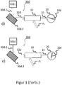
- FIG. 1 schematically shows an arrangement of a light source apparatus, a light detection component and a measured value detection in various modifications a) to e).
- FIG. 1a shows a light source 30a, which may be, for example, a reference light source 30a emitting a radiation 32a which may, at least partially, fall on the light detection component 10.
- the light sensing component 10 may be any photosensitive electronic component, such as a photodiode, a phototransistor, a photo-dependent resistor, a photomultiplier.
- a photomultiplier may have an advantage of very high photosensitivity, which may be particularly required in low light.
- the signal from the light detection component 10 can be conducted via a line 15 to a schematically represented measured value detection 20, which can display a measured value 20a.
- the measured value acquisition 20 can be embodied as a digital recording device with microprocessor control, in which, in addition to the measured values, the measurement parameters can additionally be stored, such as type of light source, time of the measurement, etc.
- the reference light source 30a can be a commercially available reference light source. It may be suitable for performing an absolute calibration.
- FIG. 1b indicates one FIG. 1a ), wherein here an alternative reference light source 30b is shown, which can emit a radiation 32b.
- the radiation 32b becomes as in FIG. 1a ) and converted, results in a measured value 20b, which may be different from the measured value 20a.
- the alternative reference light source 30b may be a light source that may be calibrated according to the method described below.
- the Figure 1c indicates one FIG. 1a ), wherein here an operating situation can be represented, in which a light source 30c can be formed by a radiation source 30c.1, which can emit an emission radiation 30c.2, which can fall on an object 30c.3 to be examined and subsequently at least partially - can be supplied as a remitted radiation 32c of the light detection component 10.
- the measured value 20c can be considerably smaller than the measured values 20a and 20b.
- radiation “remitted” by an object it is intended herein to mean, in particular, any type of radiation emanating from the object, that is to say reflection, scattering, fluorescence or fluorescence-like processes. It can be expected that the light intensity of the light source 30c may be low, which is reflected by the correspondingly small measured value 20c.
- the Figure 1d shows one to Figure 1c ) similar arrangement, in which case the entire arrangement has a temperature ⁇ 1 .
- This is symbolized by an arrow directed to the light detection component 10.
- all the components that are in Figure 1d the same temperature ⁇ 1 .
- the radiation of the radiation source 30d can be detected in the manner described above.
- the Figure 1e shows one to Figure 1d ) similar arrangement, with the same radiation source 30d. However, all components in the Figure 1e ) have a temperature ⁇ 2 , which differs from the temperature ⁇ 1 . Accordingly, the measured values 20d and 20e may differ from each other.
- the sensitivity of the light detection component 10 may be temperature dependent.
- a photomultiplier, a photodiode, a photosensitive resistor or other optical sensor as a light detection component 10
- a temporal drift of sensitivity can occur, which can not be compensated by an artificial aging prior to installation in a facility or test facility.
- a temperature of ⁇ 1 20 ° C
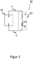
- FIG. 2 shows an alternative reference light source 50, which is formed from a low-cost LED (Light Emitting Diode) with resistor and is designated 60, which via lines a and b, which may be formed of terminals a and b of an electrical power supply 55 supplies can be.
- LED Light Emitting Diode
- Such an alternative reference light source may be installed in an industrial production facility or industrial test facility instead of the relatively expensive reference light source, so that the light detection component 10 can be recalibrated at any time.
- an emission of an LED is temperature-dependent, so that a reliable calibration is not readily possible.
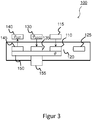
- FIG. 3 illustrates an arrangement 100 for determining a temperature-stabilized operating point of a reference light source arrangement comprising an LED.
- a programmable voltage source 115 supplies a reference light source arrangement 110 provided with a series resistor and a light-emitting diode, LED.
- a light 120 emitted by the reference light source arrangement can be detected by a light intensity measuring device 125.
- the arrangement 100 may include another programmable voltage source 130 for driving one or more temperature components 135.
- the temperature component 135 can be, for example, a Peltier element with which heating and / or cooling of a heat bath 150 is possible.
- the temperature component common or separate, may have a resistance.
- the elements forming the temperature component 135 can be controlled by the programmable voltage source 130 in such a way that the heat bath 150 can assume a predefined setpoint temperature ⁇ SOLL .
- the assembly 100 may include a thermometer 145 with data logger 140 to detect an existing temperature ⁇ IST of the thermal bath ( ⁇ ) 150.
- the thermometer 145 may be implemented as a thermocouple, temperature-dependent resistor or other temperature-dependent electronic or electrical component.
- thermo bath here means, in particular, that the relevant components, namely thermometer 145, Peltier element 135, optional resistor 135 and above all the reference light source arrangement 110 are thermally coupled to each other such that the components have the same or at least substantially the same temperature.
- the assembly 100 may also be made light-tight.
- FIG. 4 illustrates a characteristic field 200 for determining a temperature-stabilized operating point of a reference light source arrangement comprising an LED.
- the axis 205 represents a voltage U , which may be impressed on the reference light source arrangement 110 by a programmable voltage source 115.
- the axis 210 represents a light intensity I detected by the light intensity measuring device 125.
- the following procedure is used to determine a temperature-stabilized operating point of the reference light source arrangement 110 comprising an LED: First, the heat bath 150 is brought to a first setpoint temperature ⁇ 1 , so that in particular the reference light source arrangement 110 has the temperature ⁇ 1 . Then, the voltage U applied to the reference light source array 110 is varied. At the same time, the light intensity measuring device 125 detects the light intensity I emitted by the reference light source arrangement 110, which is dependent on the impressed voltage U. In this way, a first emission characteristic 215 (shown interrupted) of the reference light source arrangement 110 is detected. The skilled person will appreciate that the voltage variation is accompanied by a corresponding current variation.
- voltage variation and current variation will be considered to be synonymous, although it will be understood that in the present case, the reference light source array 110 is the same Voltage is impressed and the current adjusts accordingly. It is also clear that, if an operating point is found to impose a given voltage for a given series resistor, alternatively, a corresponding current is to be impressed.
- the heat bath 150 is brought to a second temperature ⁇ 2 and, under current variation, a second emission characteristic 220 (shown in solid lines) of the reference light source arrangement 110 is detected.
- the adjustment of the respective temperature ⁇ 1 or temperature ⁇ 2 can be carried out by a microprocessor control of the arrangement 100.
- the adjustment of the impressed voltage can also be made by the microprocessor control.
- the detection of the light 120 emitted by the light intensity measuring device 125 can also be carried out by the microprocessor control.
- an intersection point 225 of the two detected emission characteristics 215 and 220 is formed.
- the reference light source arrangement 110 emits the same light intensity I A when the voltage U A is impressed irrespective of whether the temperature ⁇ 1 or the temperature ⁇ 2 is present .
- the light intensity emitted by the reference light source array 110 is substantially independent of the temperature.
- Precise measurement at temperatures ⁇ with ⁇ 1 ⁇ ⁇ ⁇ ⁇ 2 may result in small deviations which are, however, tolerable.
- a temperature-independent light source with a relatively inexpensive reference light source arrangement 110, which is formed, for example, only from a series resistor and an LED and an impressible voltage.
Landscapes
- Physics & Mathematics (AREA)
- General Physics & Mathematics (AREA)
- Optics & Photonics (AREA)
- Investigating, Analyzing Materials By Fluorescence Or Luminescence (AREA)
- Measuring Temperature Or Quantity Of Heat (AREA)
Abstract
Description
- Optische Messungen, die sich auf eine Helligkeit einer emittierten oder rückgestrahlten Strahlung beziehen, unterliegen oftmals verschiedensten Faktoren, so dass unterschiedliche Messungen nicht zueinander in Bezug gesetzt werden können.
- Trotz Kalibrierung einer strahlungsmessenden Einrichtung mittels einer Referenzlichtlichtquelle können Messwertvariationen auftreten, die auf einen Unterschied in einer Betriebstemperatur zurückzuführen sind. In einem Labor mit einem hohen Anteil an manueller Tätigkeit ist dies durch Mehrarbeit des Laborpersonals kompensierbar. In einem industriellen Prozess einer Prüfung von Wert- oder Sicherheitsdokumenten hingegen, ist eine gesonderte Lösung erforderlich, zumal eine kommerzielle Referenzlichtquelle oftmals zu teuer ist, als dass sie in einer industriellen Anlage verbaut werden kann.
- Die vorliegende Erfindung betrifft Verfahren und Vorrichtung zur Bestimmung eines temperaturstabilisierten Arbeitspunktes einer eine LED umfassenden Referenzlichtquellenanordnung nach den unabhängigen Ansprüchen. Ausführungsformen sind in den untergeordneten Ansprüchen definiert.
- Im Weiteren werden Ausführungsformen der Erfindung mit Bezugnahme auf die Figuren der anliegenden Zeichnung erläutert. Es zeigt:
- Figur 1:
- eine Anordnung eines Lichtquellenapparats, einer Lichterfassungskomponente sowie einer Messwerterfassung in verschiedenen Abwandlungen a) bis e);
- Figur 2:
- eine Referenzlichtquelle, die aus einer LED mit Vorwiderstand gebildet ist;
- Figur 3:
- eine Anordnung zur Bestimmung eines temperaturstabilisierten Arbeitspunktes einer eine LED umfassenden Referenzlichtquellenanordnung; und
- Figur 4:
- ein Kennlinienfeld zur Bestimmung eines temperaturstabilisierten Arbeitspunktes einer eine LED umfassenden Referenzlichtquellenanordnung.
-
Figur 1 zeigt schematisch eine Anordnung eines Lichtquellenapparats, einer Lichterfassungskomponente sowie einer Messwerterfassung in verschiedenen Abwandlungen a) bis e). -
Figur 1a ) zeigt eine Lichtquelle 30a, die beispielsweise eine Referenzlichtquelle 30a sein kann, die eine Strahlung 32a emittiert, welche, zumindest teilweise, auf die Lichterfassungskomponente 10 fallen kann. Bei der Lichterfassungskomponente 10 kann es sich um jegliche lichtempfindliche elektronische Komponente handeln, beispielsweise eine Photodiode, einen Phototransistor, einen lichtabhängigen Widerstand, einen Photomultiplier. Ein Photomultiplier kann einen Vorteil einer sehr hohen Lichtempfindlichkeit aufweisen, welche insbesondere bei schwachem Licht erforderlich sein kann. - Das Signal von der Lichterfassungskomponente 10 kann über eine Leitung 15 an eine schematisch dargestellte Messwerterfassung 20 geleitet sein, die einen Messwert 20a anzeigen kann. Es ist dem Fachmann klar, dass es sich bei der Messwerterfassung 20 nicht - wie dargestellt - um ein Zeigerinstrument handeln muss. Die Messwerterfassung 20 kann als digitales Aufzeichnungsgerät mit Mikroprozessorsteuerung ausgeführt sein, worin außer den Messwerten zusätzlich die Messparameter abgespeichert werden könne, wie beispielsweise Art der Lichtquelle, Zeitpunkt der Messung, usw. Die Referenzlichtquelle 30a kann eine kommerziell erhältliche Referenzlichtquelle sein. Sie kann geeignet sein, eine absolute Kalibrierung vorzunehmen.
- Die folgenden Figuren weisen teilweise gleiche oder ähnliche Bezugszeichen auf, die eine gleiche oder ähnliche Bedeutung wie in
Figur 1a ) haben. -
Figur 1b ) zeigt eine zuFigur 1a ) ähnliche Anordnung, wobei hier eine alternative Referenzlichtquelle 30b dargestellt ist, die eine Strahlung 32b emittieren kann. Die Strahlung 32b wird wie inFigur 1a ) erfasst und gewandelt, führt zu einem Messwert 20b, der unterschiedlich zu dem Messwert 20a sein kann. Die alternative Referenzlichtquelle 30b kann eine Lichtquelle sein, die gemäß dem nachstehend beschrieben Verfahren kalibriert sein kann. - Die
Figur 1c ) zeigt eine zuFigur 1a ) ähnliche Anordnung, wobei hier eine Betriebssituation dargestellt sein kann, in der eine Lichtquelle 30c gebildet sein kann durch eine Strahlungsquelle 30c.1, die eine Emissionsstrahlung 30c.2 emittieren kann, welche auf ein zu prüfendes Objekt 30c.3 fallen kann und hernach - zumindest teilweise - als eine remittierte Strahlung 32c der Lichterfassungskomponente 10 zugeführt werden kann. Der Messwert 20c kann erheblich kleiner als die Messwerte 20a und 20b sein. - Mit von einem Objekt "remittierter" Strahlung soll hierin insbesondere jede Art von Strahlung gemeint sein, die von dem Objekt ausgeht, also Reflektion, Streuung, Fluoreszenz oder fluoreszenz-ähnliche Prozesse. Es ist zu erwarten, dass die Lichtintensität der Lichtquelle 30c gering sein kann, was durch den entsprechend geringen Messwert 20c wiedergegeben wird.
- Die
Figur 1d ) zeigt eine zurFigur 1c ) ähnliche Anordnung, wobei hier die gesamte Anordnung eine Temperatur ϑ 1 aufweist. Dies ist symbolisiert durch einen Pfeil, der auf die Lichterfassungskomponente 10 gerichtet ist. Natürlich weisen sämtliche Komponenten, die inFigur 1d ) dargestellt sind, dieselbe Temperatur ϑ 1 auf. - Die Strahlung der Strahlungsquelle 30d kann in der zuvor beschriebenen Weise erfasst werden.
- Die
Figur 1e ) zeigt eine zurFigur 1d ) ähnliche Anordnung auf, mit derselben Strahlungsquelle 30d. Allerdings können sämtliche Komponenten in derFigur 1e ) eine Temperatur ϑ 2 aufweisen, die von der Temperatur ϑ 1 abweicht. Dementsprechend kann es sein, dass die Messwerte 20d und 20e voneinander abweichen. - Mit anderen Worten kann die Empfindlichkeit der Lichterfassungskomponente 10 temperaturabhängig sein. Im Falle, beispielsweise, eines Photomultipliers, einer Photodiode, eines lichtempfindlichen Widerstands oder eines sonstigen optischen Sensors als Lichterfassungskomponente 10, kann zudem eine zeitliche Drift der Empfindlichkeit hinzutreten, die auch durch eine künstliche Alterung vor Einbau in einer Anlage oder Prüfanlage nicht kompensiert werden kann.
- Dies kann problematisch sein, weil eine Anlage, in der die Lichterfassungskomponente 10 verbaut ist, beispielsweise beim Anlaufen oder wenn das Werkshallentor offensteht, beispielsweise eine Temperatur von ϑ 1 = 20°C aufweisen, während es sein kann, dass nach einem längeren Betrieb eine Temperatur von ϑ2 = 60°C oder ϑ2 = 70°C gemessen werden kann.
- Im Falle einer Prüfung eines Wert- oder Sicherheitsdokuments kann dann eine Situation auftreten, in der eine Prüfung auf Echtheit bei unterschiedlichen Temperaturen unterschiedlich ausfallen kann. Dies gilt es zu vermeiden, um die Echtheitsprüfung mit hoher Zuverlässigkeit durchführen zu können.
-
Figur 2 zeigt eine alternative Referenzlichtquelle 50, die aus einer preiswerten LED (Leuchtdiode, Light Emitting Diode) mit Vorwiderstand gebildet ist und mit 60 bezeichnet ist, welche über Leitungen a und b, welche aus Anschlüssen a und b einer elektrischen Energieversorgung 55 gebildet sein kann, versorgt sein kann. - Eine derartige alternative Referenzlichtquelle kann in einer industriellen Produktionsanlage oder industriellen Prüfanlage anstelle der relativ teuren Referenzlichtquelle verbaut sein, so dass die Lichterfassungskomponente 10 jederzeit neu kalibriert werden kann. Allerdings ist eine Emission einer LED temperaturabhängig, so dass eine zuverlässige Kalibrierung ohne Weiteres nicht möglich ist.
-
Figur 3 veranschaulicht eine Anordnung 100 zur Bestimmung eines temperaturstabilisierten Arbeitspunktes einer eine LED umfassenden Referenzlichtquellenanordnung. Eine programmierbare Spannungsquelle 115 versorgt eine mit einem Vorwiderstand und einer Leuchtdiode, LED, versehene Referenzlichtquellenanordnung 110. Ein von der Referenzlichtquellenanordnung emittiertes Licht 120 kann von einer Lichtintensitätsmesseinrichtung 125 erfasst werden. - Die Anordnung 100 kann eine weitere programmierbare Spannungsquelle 130 zum Ansteuern einer oder mehrerer Temperaturkomponenten 135 aufweisen. Bei der Temperaturkomponente 135 kann es sich beispielsweise um ein Peltierelement handeln, mit dem eine Erwärmung und/oder eine Kühlung eines Wärmebads 150 möglich ist. Zusätzlich kann die Temperaturkomponente, gemeinsam oder getrennt, einen Widerstand aufweisen. Die die Temperaturkomponente 135 bildenden Elemente können von der programmierbaren Spannungsquelle 130 derart angesteuert werden, dass das Wärmebad 150 eine vorgegebene Solltemperatur ϑSOLL annehmen kann.
- Ferner kann die Anordnung 100 ein Thermometer 145 mit Datenlogger 140 aufweisen, um eine bestehende Temperatur ϑIST des Wärmebads (ϑ) 150 zu erfassen. Das Thermometer 145 kann als Thermoelement, temperaturabhängiger Widerstand oder sonstiges temperaturabhängiges elektronisches oder elektrisches Bauelement ausgeführt sein.
- Der Begriff "Wärmebad" bedeutet hier insbesondere, dass die relevanten Komponenten, nämlich Thermometer 145, Peltierelement 135, optionaler Widerstand 135 und vor allem die Referenzlichtquellenanordnung 110 thermisch derart miteinander gekoppelt sind, dass die Komponenten dieselbe oder zumindest im Wesentlichen dieselbe Temperatur aufweisen.
- Die Anordnung 100 kann überdies lichtdicht ausgeführt sein.
-
Figur 4 veranschaulicht ein Kennlinienfeld 200 zur Bestimmung eines temperaturstabilisierten Arbeitspunktes einer eine LED umfassenden Referenzlichtquellenanordnung. - Die Achse 205 repräsentiert eine Spannung U, die der Referenzlichtquellenanordnung 110 per programmierbarer Spannungsquelle 115 aufgeprägt sein kann. Die Achse 210 repräsentiert eine Lichtintensität I, die von der Lichtintensitätsmesseinrichtung 125 erfasst wird.
- Zur Bestimmung eines temperaturstabilisierten Arbeitspunktes der eine LED umfassenden Referenzlichtquellenanordnung 110 wird wie folgt vorgegangen:
Zunächst wird das Wärmebad 150 auf eine erste Solltemperatur ϑ 1 gebracht, so dass dann insbesondere die Referenzlichtquellenanordnung 110 die Temperatur ϑ 1 aufweist. Dann wird die der Referenzlichtquellenanordnung 110 aufgeprägte Spannung U variiert. Zeitgleich erfasst die Lichtintensitätsmesseinrichtung 125 die von der Referenzlichtquellenanordnung 110, von der aufgeprägten Spannung U abhängige, emittierte Lichtintensität I. Auf diese Weise wird eine erste Emissionskennlinie 215 (unterbrochen gezeigt) der Referenzlichtquellenanordnung 110 erfasst. Dem Fachmann ist klar, dass die Spannungsvariation mit einer dementsprechenden Stromvariation einhergeht. Insofern werden im Folgenden Spannungsvariation und Stromvariation als gleichbedeutend angesehen, wenngleich klar ist, dass im vorliegenden Fall der Referenzlichtquellenanordnung 110 die Spannung aufgeprägt wird und sich der Strom dementsprechend einstellt. Ebenso ist klar, dass, wenn ein Arbeitspunkt gefunden ist, bei vorgegebenem Vorwiderstand eine bestimmte Spannung aufzuprägen ist, alternativ ein dementsprechender Strom einzuprägen ist. - Hernach wird das Wärmebad 150 auf eine zweite Temperatur ϑ 2 gebracht und, unter Stromvariation, eine zweite Emissionskennlinie 220 (durchgezogen dargestellt) der Referenzlichtquellenanordnung 110 erfasst.
- Die Einstellung der jeweiligen Temperatur ϑ 1 bzw. Temperatur ϑ 2 kann durch eine Mikroprozessoransteuerung der Anordnung 100 vorgenommen werden. Die Einstellung der aufgeprägten Spannung kann ebenfalls durch die Mikroprozessoransteuerung vorgenommen werden. Die Erfassung des je emittierten Lichts 120 durch die Lichtintensitätsmesseinrichtung 125 kann ebenfalls durch die Mikroprozessorsteuerung vorgenommen werden.
- Sofern die LED geeignet gewählt wurde, mit geeigneter Kennlinienform, bildet sich ein Schnittpunkt 225 der beiden erfassten Emissionskennlinien 215 und 220.
- An diesem Schnittpunkt 225 emittiert die Referenzlichtquellenanordnung 110 bei aufgeprägter Spannung UA unabhängig davon, ob die Temperatur ϑ 1 oder die Temperatur ϑ 2 vorliegt, dieselbe Lichtintensität IA.
- Somit ist in diesem Arbeitspunkt die von der Referenzlichtquellenanordnung 110 emittierte Lichtintensität im Wesentlichen unabhängig von der Temperatur. Bei präziser Messung bei Temperaturen ϑ mit ϑ 1 < ϑ < ϑ 2 können möglicherweise geringe Abweichungen auftreten, die allerdings tolerierbar sind.
- Mit anderen Worten ist somit ein temperaturstabilisierter Arbeitspunkt der Referenzlichtquellenanordnung 110 gefunden.
- Somit ist es möglich, mit einer relativ preiswerten Referenzlichtquellenanordnung 110, die beispielsweise nur aus einem Vorwiderstand und einer LED sowie einer aufprägbaren Spannung gebildet ist, eine temperaturunabhängige Lichtquelle zu bilden.
- Dies kann in einer automatisierten Produktions- und oder Prüfanlage von Vorteil sein, wenn bestimmte Effekte nachzuweisen sind, beispielsweise eine Fluoreszenzintensität, die eine vorbestimmte Intensität aufweisen muss, oder sich in einem vorbestimmten Intensitätsintervall befinden muss.
Claims (6)
- Verfahren zur Bestimmung eines temperaturstabilisierten Arbeitspunktes einer eine LED umfassenden Referenzlichtquellenanordnung, umfassend:a) bei einer ersten Temperatur: Erfassen, unter Stromvariation, einer ersten Emissionskennlinie der Referenzlichtquellenanordnung;b) bei einer zweiten Temperatur: Erfassen, unter Stromvariation, einer zweiten Emissionskennlinie der Referenzlichtquellenanordnung;c) nach Aufnahme der ersten Emissionskennlinie und der zweiten Emissionskennlinie:i. Auffinden eines von null verschiedenen Stromes, bei dem der diesem Strom zugeordnete Intensitätswert auf der ersten Emissionskennlinie denselben Intensitätswert wie der diesem Strom zugeordnete Intensitätswert auf der zweiten Emissionskennlinie hat; undii. Wahl des so bestimmten Stromes als Strom des Arbeitspunktes.
- Verfahren nach Anspruch 1, wobei die Stromvariation durch Variation einer aufgeprägten Spannung bewirkt wird.
- Verfahren nach einem der voranstehenden Ansprüche, wobei die Stromvariationen und die Temperatureinstellungen automatisiert vorgenommen werden.
- Verfahren nach einem der voranstehenden Ansprüche, wobei die erfassten Emissionskennlinien automatisiert erfasst werden.
- Verfahren nach einem der voranstehenden Ansprüche, wobei der Arbeitspunkt automatisiert bestimmt wird.
- Vorrichtung zur Ausführung eines Verfahrens nach einem der voranstehenden Ansprüche.
Applications Claiming Priority (1)
| Application Number | Priority Date | Filing Date | Title |
|---|---|---|---|
| DE102017128370.6A DE102017128370A1 (de) | 2017-11-30 | 2017-11-30 | Temperatur- und intensitätskalibrierte Referenzlichtquelle |
Publications (2)
| Publication Number | Publication Date |
|---|---|
| EP3492936A1 true EP3492936A1 (de) | 2019-06-05 |
| EP3492936B1 EP3492936B1 (de) | 2020-03-04 |
Family
ID=64500234
Family Applications (1)
| Application Number | Title | Priority Date | Filing Date |
|---|---|---|---|
| EP18208544.9A Active EP3492936B1 (de) | 2017-11-30 | 2018-11-27 | Temperatur- und intensitätskalibrierte referenzlichtquelle |
Country Status (2)
| Country | Link |
|---|---|
| EP (1) | EP3492936B1 (de) |
| DE (1) | DE102017128370A1 (de) |
Citations (2)
| Publication number | Priority date | Publication date | Assignee | Title |
|---|---|---|---|---|
| EP0856726A1 (de) * | 1997-01-30 | 1998-08-05 | TEMIC TELEFUNKEN microelectronic GmbH | Verfahren zur Temperaturkompensation bei Messsystemen |
| CH707089A2 (de) * | 2012-10-02 | 2014-04-15 | Rieter Cz Sro | Verfahren zur Generierung der Lichtstrahlung und Einschaltung der Leuchtdiode der Strahlungsquelle in einem optischen Sensor zur Verfolgung eines linearen Textilmaterials. |
Family Cites Families (2)
| Publication number | Priority date | Publication date | Assignee | Title |
|---|---|---|---|---|
| DE602004024123D1 (de) * | 2003-12-04 | 2009-12-24 | Nxp Bv | Magnetfeldempfindliche sensoranordnung |
| US9491824B2 (en) * | 2014-08-05 | 2016-11-08 | Svetlana Eden | Method and apparatus for precise temperature brightness compensation of LED |
-
2017
- 2017-11-30 DE DE102017128370.6A patent/DE102017128370A1/de not_active Withdrawn
-
2018
- 2018-11-27 EP EP18208544.9A patent/EP3492936B1/de active Active
Patent Citations (2)
| Publication number | Priority date | Publication date | Assignee | Title |
|---|---|---|---|---|
| EP0856726A1 (de) * | 1997-01-30 | 1998-08-05 | TEMIC TELEFUNKEN microelectronic GmbH | Verfahren zur Temperaturkompensation bei Messsystemen |
| CH707089A2 (de) * | 2012-10-02 | 2014-04-15 | Rieter Cz Sro | Verfahren zur Generierung der Lichtstrahlung und Einschaltung der Leuchtdiode der Strahlungsquelle in einem optischen Sensor zur Verfolgung eines linearen Textilmaterials. |
Also Published As
| Publication number | Publication date |
|---|---|
| DE102017128370A1 (de) | 2019-06-06 |
| EP3492936B1 (de) | 2020-03-04 |
Similar Documents
| Publication | Publication Date | Title |
|---|---|---|
| DE102008046725B4 (de) | Infrarotzielobjekt-Temperaturkorrektursystem und- verfahren | |
| EP0856726B1 (de) | Verfahren zur Temperaturkompensation bei Messsystemen | |
| DE69201923T2 (de) | Gerät und Verfahren zum Einbrennen. | |
| DE19613229C2 (de) | Verfahren zur Kalibrierung eines Strahlungsthermometers | |
| DE102015106805A1 (de) | Temperaturkalibration für Messgerät | |
| DE102016211821A1 (de) | Verfahren zur kontaktfreien Ermittlung einer Temperatur sowie Infrarot-Messsystem | |
| WO1996009667A1 (de) | Verfahren zur temperaturkompensation von optoelektronischen bauelementen und insbesondere von optoelektronischen halbleitern | |
| DE102019124344B4 (de) | Verfahren und Vorrichtung für eine Überprüfung der inneren Beschaffenheit eines Prüfobjektes mittels eines aufgeprägten Wärmeflusses | |
| EP3492936B1 (de) | Temperatur- und intensitätskalibrierte referenzlichtquelle | |
| DE102005049175B4 (de) | Infrarotgasanalysator und Verfahren zur Infrarotgasanalyse | |
| DE102010026992A1 (de) | Temperaturmessung unter Verwendung einer Diode mit Sättigungsstromkompensation | |
| DE102016211812A1 (de) | Verfahren zur kontaktfreien Ermittlung einer Temperatur sowie Infrarot-Messsystem | |
| EP3299803A1 (de) | Verfahren zur kalibrierung einer temperierung bei thermischen analysen von proben | |
| DE102016212810B4 (de) | Verfahren und Messsystem für die Prüfung eines Bauteils durch aktive Thermografie | |
| DE102007040224A1 (de) | Verfahren zum Betrieb eines Garnsensors und Garnsensor | |
| EP2592402A1 (de) | Komponententemperaturbestimmung | |
| EP2211205B1 (de) | Verfahren zur Erfassung von Objekten in einem Überwachungsbereich und optischer Sensor zur Durchführung des Verfahrens | |
| EP3088866A1 (de) | Verfahren zum automatischen kalibrieren eines optischen messgerätes und optisches messgerät | |
| DE102009019774A1 (de) | Verfahren und Vorrichtung zur thermischen Überwachung von Ausfallprozessen | |
| DE102022128729A1 (de) | Messgerät zum dimensionellen Messen, Verwendung des Messgeräts und Verfahren zum dimensionellen Messen | |
| DE102021211068A1 (de) | Vorrichtung, Verfahren und System zum Analysieren von mindestens einem Textil, und Spektrometer | |
| WO2007077208A2 (de) | Verfahren und system zur generierung eines hinsichtlich der präsenz eines stoffes innerhalb einer probe indikativen messergebnisses auf grundlage einer spektormetrischen messung | |
| EP2372336B1 (de) | System und Verfahren zur Feststellung eines Fehlerzustandes von einem Fahrzeugbauteil mittels der Analyse eines thermografischen Bildes des Bauteils. | |
| DE102008061458A1 (de) | Verfahren zum Ermitteln eines Emissionsgrades für eine Emissionsgradkorrektur zum Erhöhen einer Messgenauigkeit einer Messvorrichtung für Thermografie und Pyrometrie und eine entsprechende Messvorrichtung | |
| DE102016015424B4 (de) | Vorrichtung zur Bestimmung einer Konzentration eines Gases |
Legal Events
| Date | Code | Title | Description |
|---|---|---|---|
| PUAI | Public reference made under article 153(3) epc to a published international application that has entered the european phase |
Free format text: ORIGINAL CODE: 0009012 |
|
| STAA | Information on the status of an ep patent application or granted ep patent |
Free format text: STATUS: THE APPLICATION HAS BEEN PUBLISHED |
|
| AK | Designated contracting states |
Kind code of ref document: A1 Designated state(s): AL AT BE BG CH CY CZ DE DK EE ES FI FR GB GR HR HU IE IS IT LI LT LU LV MC MK MT NL NO PL PT RO RS SE SI SK SM TR |
|
| AX | Request for extension of the european patent |
Extension state: BA ME |
|
| STAA | Information on the status of an ep patent application or granted ep patent |
Free format text: STATUS: REQUEST FOR EXAMINATION WAS MADE |
|
| 17P | Request for examination filed |
Effective date: 20190712 |
|
| RBV | Designated contracting states (corrected) |
Designated state(s): AL AT BE BG CH CY CZ DE DK EE ES FI FR GB GR HR HU IE IS IT LI LT LU LV MC MK MT NL NO PL PT RO RS SE SI SK SM TR |
|
| GRAP | Despatch of communication of intention to grant a patent |
Free format text: ORIGINAL CODE: EPIDOSNIGR1 |
|
| STAA | Information on the status of an ep patent application or granted ep patent |
Free format text: STATUS: GRANT OF PATENT IS INTENDED |
|
| INTG | Intention to grant announced |
Effective date: 20190925 |
|
| GRAS | Grant fee paid |
Free format text: ORIGINAL CODE: EPIDOSNIGR3 |
|
| GRAA | (expected) grant |
Free format text: ORIGINAL CODE: 0009210 |
|
| STAA | Information on the status of an ep patent application or granted ep patent |
Free format text: STATUS: THE PATENT HAS BEEN GRANTED |
|
| AK | Designated contracting states |
Kind code of ref document: B1 Designated state(s): AL AT BE BG CH CY CZ DE DK EE ES FI FR GB GR HR HU IE IS IT LI LT LU LV MC MK MT NL NO PL PT RO RS SE SI SK SM TR |
|
| REG | Reference to a national code |
Ref country code: GB Ref legal event code: FG4D Free format text: NOT ENGLISH |
|
| REG | Reference to a national code |
Ref country code: CH Ref legal event code: EP |
|
| REG | Reference to a national code |
Ref country code: AT Ref legal event code: REF Ref document number: 1241015 Country of ref document: AT Kind code of ref document: T Effective date: 20200315 |
|
| REG | Reference to a national code |
Ref country code: DE Ref legal event code: R096 Ref document number: 502018000890 Country of ref document: DE |
|
| REG | Reference to a national code |
Ref country code: IE Ref legal event code: FG4D Free format text: LANGUAGE OF EP DOCUMENT: GERMAN |
|
| PG25 | Lapsed in a contracting state [announced via postgrant information from national office to epo] |
Ref country code: NO Free format text: LAPSE BECAUSE OF FAILURE TO SUBMIT A TRANSLATION OF THE DESCRIPTION OR TO PAY THE FEE WITHIN THE PRESCRIBED TIME-LIMIT Effective date: 20200604 Ref country code: RS Free format text: LAPSE BECAUSE OF FAILURE TO SUBMIT A TRANSLATION OF THE DESCRIPTION OR TO PAY THE FEE WITHIN THE PRESCRIBED TIME-LIMIT Effective date: 20200304 Ref country code: FI Free format text: LAPSE BECAUSE OF FAILURE TO SUBMIT A TRANSLATION OF THE DESCRIPTION OR TO PAY THE FEE WITHIN THE PRESCRIBED TIME-LIMIT Effective date: 20200304 |
|
| REG | Reference to a national code |
Ref country code: NL Ref legal event code: MP Effective date: 20200304 |
|
| PG25 | Lapsed in a contracting state [announced via postgrant information from national office to epo] |
Ref country code: SE Free format text: LAPSE BECAUSE OF FAILURE TO SUBMIT A TRANSLATION OF THE DESCRIPTION OR TO PAY THE FEE WITHIN THE PRESCRIBED TIME-LIMIT Effective date: 20200304 Ref country code: LV Free format text: LAPSE BECAUSE OF FAILURE TO SUBMIT A TRANSLATION OF THE DESCRIPTION OR TO PAY THE FEE WITHIN THE PRESCRIBED TIME-LIMIT Effective date: 20200304 Ref country code: GR Free format text: LAPSE BECAUSE OF FAILURE TO SUBMIT A TRANSLATION OF THE DESCRIPTION OR TO PAY THE FEE WITHIN THE PRESCRIBED TIME-LIMIT Effective date: 20200605 Ref country code: HR Free format text: LAPSE BECAUSE OF FAILURE TO SUBMIT A TRANSLATION OF THE DESCRIPTION OR TO PAY THE FEE WITHIN THE PRESCRIBED TIME-LIMIT Effective date: 20200304 Ref country code: BG Free format text: LAPSE BECAUSE OF FAILURE TO SUBMIT A TRANSLATION OF THE DESCRIPTION OR TO PAY THE FEE WITHIN THE PRESCRIBED TIME-LIMIT Effective date: 20200604 |
|
| REG | Reference to a national code |
Ref country code: LT Ref legal event code: MG4D |
|
| PG25 | Lapsed in a contracting state [announced via postgrant information from national office to epo] |
Ref country code: NL Free format text: LAPSE BECAUSE OF FAILURE TO SUBMIT A TRANSLATION OF THE DESCRIPTION OR TO PAY THE FEE WITHIN THE PRESCRIBED TIME-LIMIT Effective date: 20200304 |
|
| PG25 | Lapsed in a contracting state [announced via postgrant information from national office to epo] |
Ref country code: EE Free format text: LAPSE BECAUSE OF FAILURE TO SUBMIT A TRANSLATION OF THE DESCRIPTION OR TO PAY THE FEE WITHIN THE PRESCRIBED TIME-LIMIT Effective date: 20200304 Ref country code: LT Free format text: LAPSE BECAUSE OF FAILURE TO SUBMIT A TRANSLATION OF THE DESCRIPTION OR TO PAY THE FEE WITHIN THE PRESCRIBED TIME-LIMIT Effective date: 20200304 Ref country code: SM Free format text: LAPSE BECAUSE OF FAILURE TO SUBMIT A TRANSLATION OF THE DESCRIPTION OR TO PAY THE FEE WITHIN THE PRESCRIBED TIME-LIMIT Effective date: 20200304 Ref country code: SK Free format text: LAPSE BECAUSE OF FAILURE TO SUBMIT A TRANSLATION OF THE DESCRIPTION OR TO PAY THE FEE WITHIN THE PRESCRIBED TIME-LIMIT Effective date: 20200304 Ref country code: IS Free format text: LAPSE BECAUSE OF FAILURE TO SUBMIT A TRANSLATION OF THE DESCRIPTION OR TO PAY THE FEE WITHIN THE PRESCRIBED TIME-LIMIT Effective date: 20200704 Ref country code: PT Free format text: LAPSE BECAUSE OF FAILURE TO SUBMIT A TRANSLATION OF THE DESCRIPTION OR TO PAY THE FEE WITHIN THE PRESCRIBED TIME-LIMIT Effective date: 20200729 Ref country code: ES Free format text: LAPSE BECAUSE OF FAILURE TO SUBMIT A TRANSLATION OF THE DESCRIPTION OR TO PAY THE FEE WITHIN THE PRESCRIBED TIME-LIMIT Effective date: 20200304 Ref country code: CZ Free format text: LAPSE BECAUSE OF FAILURE TO SUBMIT A TRANSLATION OF THE DESCRIPTION OR TO PAY THE FEE WITHIN THE PRESCRIBED TIME-LIMIT Effective date: 20200304 Ref country code: RO Free format text: LAPSE BECAUSE OF FAILURE TO SUBMIT A TRANSLATION OF THE DESCRIPTION OR TO PAY THE FEE WITHIN THE PRESCRIBED TIME-LIMIT Effective date: 20200304 |
|
| REG | Reference to a national code |
Ref country code: DE Ref legal event code: R097 Ref document number: 502018000890 Country of ref document: DE |
|
| PLBE | No opposition filed within time limit |
Free format text: ORIGINAL CODE: 0009261 |
|
| STAA | Information on the status of an ep patent application or granted ep patent |
Free format text: STATUS: NO OPPOSITION FILED WITHIN TIME LIMIT |
|
| PG25 | Lapsed in a contracting state [announced via postgrant information from national office to epo] |
Ref country code: IT Free format text: LAPSE BECAUSE OF FAILURE TO SUBMIT A TRANSLATION OF THE DESCRIPTION OR TO PAY THE FEE WITHIN THE PRESCRIBED TIME-LIMIT Effective date: 20200304 Ref country code: DK Free format text: LAPSE BECAUSE OF FAILURE TO SUBMIT A TRANSLATION OF THE DESCRIPTION OR TO PAY THE FEE WITHIN THE PRESCRIBED TIME-LIMIT Effective date: 20200304 |
|
| 26N | No opposition filed |
Effective date: 20201207 |
|
| PG25 | Lapsed in a contracting state [announced via postgrant information from national office to epo] |
Ref country code: PL Free format text: LAPSE BECAUSE OF FAILURE TO SUBMIT A TRANSLATION OF THE DESCRIPTION OR TO PAY THE FEE WITHIN THE PRESCRIBED TIME-LIMIT Effective date: 20200304 |
|
| PG25 | Lapsed in a contracting state [announced via postgrant information from national office to epo] |
Ref country code: MC Free format text: LAPSE BECAUSE OF FAILURE TO SUBMIT A TRANSLATION OF THE DESCRIPTION OR TO PAY THE FEE WITHIN THE PRESCRIBED TIME-LIMIT Effective date: 20200304 |
|
| PG25 | Lapsed in a contracting state [announced via postgrant information from national office to epo] |
Ref country code: LU Free format text: LAPSE BECAUSE OF NON-PAYMENT OF DUE FEES Effective date: 20201127 |
|
| REG | Reference to a national code |
Ref country code: BE Ref legal event code: MM Effective date: 20201130 |
|
| PG25 | Lapsed in a contracting state [announced via postgrant information from national office to epo] |
Ref country code: IE Free format text: LAPSE BECAUSE OF NON-PAYMENT OF DUE FEES Effective date: 20201127 |
|
| PG25 | Lapsed in a contracting state [announced via postgrant information from national office to epo] |
Ref country code: TR Free format text: LAPSE BECAUSE OF FAILURE TO SUBMIT A TRANSLATION OF THE DESCRIPTION OR TO PAY THE FEE WITHIN THE PRESCRIBED TIME-LIMIT Effective date: 20200304 Ref country code: MT Free format text: LAPSE BECAUSE OF FAILURE TO SUBMIT A TRANSLATION OF THE DESCRIPTION OR TO PAY THE FEE WITHIN THE PRESCRIBED TIME-LIMIT Effective date: 20200304 Ref country code: CY Free format text: LAPSE BECAUSE OF FAILURE TO SUBMIT A TRANSLATION OF THE DESCRIPTION OR TO PAY THE FEE WITHIN THE PRESCRIBED TIME-LIMIT Effective date: 20200304 |
|
| PG25 | Lapsed in a contracting state [announced via postgrant information from national office to epo] |
Ref country code: MK Free format text: LAPSE BECAUSE OF FAILURE TO SUBMIT A TRANSLATION OF THE DESCRIPTION OR TO PAY THE FEE WITHIN THE PRESCRIBED TIME-LIMIT Effective date: 20200304 Ref country code: AL Free format text: LAPSE BECAUSE OF FAILURE TO SUBMIT A TRANSLATION OF THE DESCRIPTION OR TO PAY THE FEE WITHIN THE PRESCRIBED TIME-LIMIT Effective date: 20200304 |
|
| REG | Reference to a national code |
Ref country code: CH Ref legal event code: PL |
|
| PG25 | Lapsed in a contracting state [announced via postgrant information from national office to epo] |
Ref country code: BE Free format text: LAPSE BECAUSE OF NON-PAYMENT OF DUE FEES Effective date: 20201130 |
|
| P01 | Opt-out of the competence of the unified patent court (upc) registered |
Effective date: 20230526 |
|
| PG25 | Lapsed in a contracting state [announced via postgrant information from national office to epo] |
Ref country code: LI Free format text: LAPSE BECAUSE OF NON-PAYMENT OF DUE FEES Effective date: 20220630 Ref country code: CH Free format text: LAPSE BECAUSE OF NON-PAYMENT OF DUE FEES Effective date: 20220630 |
|
| PG25 | Lapsed in a contracting state [announced via postgrant information from national office to epo] |
Ref country code: SI Free format text: LAPSE BECAUSE OF FAILURE TO SUBMIT A TRANSLATION OF THE DESCRIPTION OR TO PAY THE FEE WITHIN THE PRESCRIBED TIME-LIMIT Effective date: 20200304 |
|
| REG | Reference to a national code |
Ref country code: AT Ref legal event code: MM01 Ref document number: 1241015 Country of ref document: AT Kind code of ref document: T Effective date: 20231127 |
|
| PG25 | Lapsed in a contracting state [announced via postgrant information from national office to epo] |
Ref country code: AT Free format text: LAPSE BECAUSE OF NON-PAYMENT OF DUE FEES Effective date: 20231127 |
|
| PG25 | Lapsed in a contracting state [announced via postgrant information from national office to epo] |
Ref country code: AT Free format text: LAPSE BECAUSE OF NON-PAYMENT OF DUE FEES Effective date: 20231127 |
|
| PGFP | Annual fee paid to national office [announced via postgrant information from national office to epo] |
Ref country code: DE Payment date: 20251118 Year of fee payment: 8 |
|
| PGFP | Annual fee paid to national office [announced via postgrant information from national office to epo] |
Ref country code: GB Payment date: 20251120 Year of fee payment: 8 |
|
| PGFP | Annual fee paid to national office [announced via postgrant information from national office to epo] |
Ref country code: FR Payment date: 20251120 Year of fee payment: 8 |
|
| PGFP | Annual fee paid to national office [announced via postgrant information from national office to epo] |
Ref country code: AT Payment date: 20260410 Year of fee payment: 5 |