EP3492811B1 - Centrales nucléaires - Google Patents
Centrales nucléaires Download PDFInfo
- Publication number
- EP3492811B1 EP3492811B1 EP18205298.5A EP18205298A EP3492811B1 EP 3492811 B1 EP3492811 B1 EP 3492811B1 EP 18205298 A EP18205298 A EP 18205298A EP 3492811 B1 EP3492811 B1 EP 3492811B1
- Authority
- EP
- European Patent Office
- Prior art keywords
- steam
- coolant
- steam generator
- nuclear power
- power plant
- Prior art date
- Legal status (The legal status is an assumption and is not a legal conclusion. Google has not performed a legal analysis and makes no representation as to the accuracy of the status listed.)
- Active
Links
- 239000002826 coolant Substances 0.000 claims description 76
- 239000012530 fluid Substances 0.000 claims description 32
- 238000001035 drying Methods 0.000 claims description 13
- 238000000034 method Methods 0.000 claims description 8
- 230000005484 gravity Effects 0.000 claims description 6
- XLYOFNOQVPJJNP-UHFFFAOYSA-N water Substances O XLYOFNOQVPJJNP-UHFFFAOYSA-N 0.000 description 23
- 238000001816 cooling Methods 0.000 description 8
- 239000007788 liquid Substances 0.000 description 7
- 230000004888 barrier function Effects 0.000 description 4
- 239000000498 cooling water Substances 0.000 description 4
- 230000005611 electricity Effects 0.000 description 3
- 238000001514 detection method Methods 0.000 description 2
- 229910000831 Steel Inorganic materials 0.000 description 1
- 238000003491 array Methods 0.000 description 1
- 239000000446 fuel Substances 0.000 description 1
- 239000003758 nuclear fuel Substances 0.000 description 1
- 238000013021 overheating Methods 0.000 description 1
- 230000000630 rising effect Effects 0.000 description 1
- 239000010959 steel Substances 0.000 description 1
- 239000002918 waste heat Substances 0.000 description 1
Images

Classifications
-
- G—PHYSICS
- G21—NUCLEAR PHYSICS; NUCLEAR ENGINEERING
- G21C—NUCLEAR REACTORS
- G21C15/00—Cooling arrangements within the pressure vessel containing the core; Selection of specific coolants
- G21C15/18—Emergency cooling arrangements; Removing shut-down heat
-
- F—MECHANICAL ENGINEERING; LIGHTING; HEATING; WEAPONS; BLASTING
- F22—STEAM GENERATION
- F22B—METHODS OF STEAM GENERATION; STEAM BOILERS
- F22B1/00—Methods of steam generation characterised by form of heating method
- F22B1/02—Methods of steam generation characterised by form of heating method by exploitation of the heat content of hot heat carriers
- F22B1/023—Methods of steam generation characterised by form of heating method by exploitation of the heat content of hot heat carriers with heating tubes, for nuclear reactors as far as they are not classified, according to a specified heating fluid, in another group
-
- F—MECHANICAL ENGINEERING; LIGHTING; HEATING; WEAPONS; BLASTING
- F22—STEAM GENERATION
- F22B—METHODS OF STEAM GENERATION; STEAM BOILERS
- F22B1/00—Methods of steam generation characterised by form of heating method
- F22B1/02—Methods of steam generation characterised by form of heating method by exploitation of the heat content of hot heat carriers
- F22B1/08—Methods of steam generation characterised by form of heating method by exploitation of the heat content of hot heat carriers the heat carrier being steam
- F22B1/12—Methods of steam generation characterised by form of heating method by exploitation of the heat content of hot heat carriers the heat carrier being steam produced by an indirect cyclic process
- F22B1/123—Steam generators downstream of a nuclear boiling water reactor
-
- F—MECHANICAL ENGINEERING; LIGHTING; HEATING; WEAPONS; BLASTING
- F22—STEAM GENERATION
- F22B—METHODS OF STEAM GENERATION; STEAM BOILERS
- F22B35/00—Control systems for steam boilers
- F22B35/004—Control systems for steam generators of nuclear power plants
-
- F—MECHANICAL ENGINEERING; LIGHTING; HEATING; WEAPONS; BLASTING
- F22—STEAM GENERATION
- F22B—METHODS OF STEAM GENERATION; STEAM BOILERS
- F22B37/00—Component parts or details of steam boilers
- F22B37/02—Component parts or details of steam boilers applicable to more than one kind or type of steam boiler
- F22B37/26—Steam-separating arrangements
- F22B37/268—Steam-separating arrangements specially adapted for steam generators of nuclear power plants
-
- G—PHYSICS
- G21—NUCLEAR PHYSICS; NUCLEAR ENGINEERING
- G21C—NUCLEAR REACTORS
- G21C15/00—Cooling arrangements within the pressure vessel containing the core; Selection of specific coolants
- G21C15/02—Arrangements or disposition of passages in which heat is transferred to the coolant; Coolant flow control devices
-
- G—PHYSICS
- G21—NUCLEAR PHYSICS; NUCLEAR ENGINEERING
- G21D—NUCLEAR POWER PLANT
- G21D3/00—Control of nuclear power plant
- G21D3/04—Safety arrangements
-
- Y—GENERAL TAGGING OF NEW TECHNOLOGICAL DEVELOPMENTS; GENERAL TAGGING OF CROSS-SECTIONAL TECHNOLOGIES SPANNING OVER SEVERAL SECTIONS OF THE IPC; TECHNICAL SUBJECTS COVERED BY FORMER USPC CROSS-REFERENCE ART COLLECTIONS [XRACs] AND DIGESTS
- Y02—TECHNOLOGIES OR APPLICATIONS FOR MITIGATION OR ADAPTATION AGAINST CLIMATE CHANGE
- Y02E—REDUCTION OF GREENHOUSE GAS [GHG] EMISSIONS, RELATED TO ENERGY GENERATION, TRANSMISSION OR DISTRIBUTION
- Y02E30/00—Energy generation of nuclear origin
Definitions
- the present disclosure relates to nuclear power plants.
- a nuclear power plant typically includes a nuclear reactor, a primary circuit, a heat exchanger, a secondary circuit, and a turbine.
- the primary fluid in the primary circuit is heated by the nuclear reactor.
- the primary fluid flows to the heat exchanger, where it heats secondary fluid in the secondary circuit.
- the heated secondary fluid is then used to drive the turbine to generate electricity.
- cooling is provided in operation by the circulation of heat in the primary fluid (or coolant) of the primary circuit, exchanging that heat with the secondary cooling system via the heat exchanger (e.g. steam generator or boiler) and then exchanging this heat with an ultimate heat sink of the power station.
- the ultimate heat sink may be the sea, a cooling tower, or some other alternative heat sink.
- a nuclear power plant includes safety systems such that if there is a failure (e.g. no electricity) meaning that the usual cooling flow described above is not available, the reactor is prevented from overheating in its shutdown state, where the reactor will still be generating substantial heat in the form of decay heat.
- a failure e.g. no electricity
- GB2550352 discloses a nuclear power plant having a reservoir of coolant provided at a position closer to the reactor chamber than the ultimate heat sink; a first feed arrangement is provided and configured to cool the reactor using the coolant of the reservoir as an alternative to using the ultimate heat sink; a second feed arrangement 32 is provided and configured to flood the reactor chamber with coolant from the reservoir in the event of an emergency.
- GB2535848 discloses a secondary side passive waste heat removal system, with a steam pipeline that hermetically penetrates a containment vessel and is connected to an outlet of a steam generator arranged in the containment vessel as well as a cooling water tank arranged outside the containment vessel, a water supply pipeline also hermetically penetrates the containment vessel and is connected to a cooling water tank and an inlet of the steam generator, and the steam pipeline, the water supply pipeline and the cooling water tank form a circulating channel so as to remove decay heat in the containment vessel out of the containment vessel.
- the threshold level may be set such that, provided that the coolant stays below the threshold level, the or each or at least some of the steam separators function to dry steam within the steam generator.
- the threshold level may be set such that, provided that the coolant in the secondary side of the steam generator stays below the threshold level, the or each or at least some of the steam separators function to dry steam within the steam generator.
- the threshold level may be defined by a lower limit of the steam drying zone.
- the steam drying zone may be defined as the region within which steam drying occurs, or the operable range of the or each steam separator.
- the or each steam separator may at least partially lie within the steam drying zone.
- the coolant reservoir may contain coolant such as water.
- the level of the coolant within the coolant reservoir may be at or below the threshold level.
- the coolant reservoir may be located inside a reactor containment.
- the coolant reservoir may circumferentially surround the steam generator, reactor arrangement or reactor containment structure.
- the coolant reservoir may be provided with a valve, such as a breather valve, operable to provide fluid communication between the coolant reservoir and the outside thereof.
- the power plant may further comprise a depressurisation valve operable to reduce the pressure within the steam generator.
- the depressurisation valve may be operable to route steam to a subsidiary location.
- the power plant may further comprise a feed conduit between the coolant reservoir and the steam generator.
- the feed conduit may be provided with a valve operable to allow fluid communication between the coolant reservoir and the steam generator.
- the method may further comprise opening a valve so as to provide fluid communication between the coolant reservoir and the outside thereof.
- the method may further comprise opening a depressurisation valve so as to reduce the pressure within the steam generator. Opening the depressurisation valve may route steam to a subsidiary location.
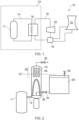
- a nuclear power plant is indicated generally at 10.
- the plant includes a reactor pressure vessel (RPV) 11 housing nuclear fuel, a primary fluid circuit 14, a heat exchanger which in this example is a steam generator 16, a secondary fluid circuit 18 and a turbine 20.
- the turbine 20 is housed within a turbine hall (or building or chamber) (not shown) and the reactor vessel 11 is housed within a reactor chamber 24 (or building or hall).
- the reactor chamber 24 is separated from the turbine hall by a containment barrier.
- the barrier may be made, for example, from concrete and/or steel.
- the primary fluid in the primary circuit 14 is heated by the thermal energy generated in the reactor pressure vessel 11.
- the primary fluid then flows to the steam generator 16, where it heats the secondary fluid, which in this example is water, to generate steam.
- the generated steam is then used to drive the turbine 20, thereby generating electricity.
- the secondary fluid flows to a condenser 19 where it is cooled using water from an ultimate heat sink 21.
- the ultimate heat sink may be a cooling tower, river, lake, or any other suitable supply of cooling water.
- the secondary circuit pumps may stop operating, meaning that the water in the secondary fluid circuit 18 will not continue to flow, causing a build-up of heat in the reactor pressure vessel 11. It is therefore desirable to provide a means for heat removal over extended periods of time from the immediate shut down state through to thermal roll-over of a plant without any intervention or power requirements.
- FIG. 2 shows a part of the nuclear power plant which, as will be described in detail below, includes a local ultimate heatsink 29 for removing heat from the primary fluid circuit (and therefore from the reactor pressure vessel 11) in an emergency (e.g. during a power outage).
- the reactor is a close-coupled reactor which means that the steam generator 16 is closely coupled to the reactor pressure vessel 11.
- the steam generator 16 is adjacent to the reactor pressure vessel 11 and is both mechanically and fluidly connected to the reactor pressure vessel 11.
- Only one steam generator 16 is shown, it should be appreciated that a plurality of steam generators 16 may be provided.
- the entire assembly of the reactor pressure vessel 11 and the steam generator 16 is housed in the reactor chamber 24 and positioned proximal to a base of the reactor chamber 24.
- the steam generator 16 comprises two substantially horizontal arrays of steam separators 28, one located above the other in an upper region of the steam generator 16.
- the steam separators 28 are configured to dry the steam generated within the steam generator 16 such that water droplets are removed from vapour, thereby generating substantially dry steam.
- Substantially dry steam may be considered to be steam that contains less than 5% liquid water, or less than 4% liquid water, or less than 3% liquid water, or less than 2% liquid water, or less than 1% liquid water, or less than 0.5% liquid water, or less than 0.25% liquid water.
- the steam separators 28 therefore ensure that substantially dry steam is fed to the turbine 20. This may be highly desirable as wet steam can damage turbines and it carries less energy than dry steam.
- two rows of steam separators 28 are shown, it should be appreciated that any suitable number of separators could be used.
- the steam separators 28 define what is referred to in this specification as a steam drying zone 26 in the upper region of the steam generator 16.
- the steam drying zone 26 is the region of the steam generator 16 within which moisture droplets are removed from the wet steam by the steam separators 28 so as to generate substantially dry steam.
- the steam separators 28 are at least partly located within the steam drying zone 26.
- the steam generator 16 further comprises a depressurization valve 30 which is operable to depressurize the steam generator 16.
- the valve 30 may be operated by a motor or solenoid system, or via a remote control system, for example. In other arrangements, the valve 30 may comprise an electro-mechanical valve which may open automatically on loss of electrical power.
- the depressurization valve 30 can be operated to route the steam to a subsidiary location (i.e. a location or to equipment that is not the main turbine 20.
- the subsidiary location may be the reactor containment, the external atmosphere, a separate tank, an ultimate heat sink, or a local ultimate heat sink (which is described below).
- the nuclear power plant 10 further comprises a local ultimate heat sink (LUHS) in the form of a coolant reservoir 29.
- the local ultimate heat sink 29 is distinct from the ultimate heat sink 21 and is provided close (i.e. local) to the reactor pressure vessel 11.
- the coolant reservoir 29 is a water reservoir and contains a volume of water.
- other fluid coolants could be used.
- the coolant reservoir 29 can be used to draw heat away from the primary fluid circuit 14 in emergency conditions. Such an emergency condition may occur where the secondary fluid circuit 18 is not capable of drawing heat away from the primary fluid circuit 14. This could be because either fluid is not circulating in the secondary fluid circuit 18, or because the ultimate heat sink 21 is not appropriately cooling the secondary fluid.
- the coolant reservoir 29 is provided outside of the reactor chamber 24 such that there is a physical barrier (e.g. a containment barrier) between the reactor chamber 24 and the reservoir 29.
- a physical barrier e.g. a containment barrier
- the coolant reservoir 29 may be provided within the reactor chamber 24.
- the bottom of the reservoir 29 is fluidically connected to the bottom of the steam generator 16 by a feed conduit 38.
- the feed conduit 38 is provided with a valve 34, for example an electromechanical valve, which under emergency conditions opens (or can be opened) such that coolant within the reservoir 29 is supplied to the steam generator 16 under gravity.
- the upper region of the coolant reservoir 29 is also provided with a breather valve 36 which can be opened to provide fluid communication between the coolant reservoir 29 and the atmosphere (or external environment), thereby equalising the pressure between the inside and the outside of the reservoir 29. This may assist in the flow of coolant from the reservoir 29 to the steam generator 16 in emergency conditions.
- the coolant reservoir 29 is filled with coolant, which in this arrangement is water, to a fill level that ensures that when coolant is gravity-fed to the steam generator 16 (i.e. by opening valves 30, 34, 36) the coolant does not rise above a threshold level 32 defined by the steam drying zone 26.
- the threshold level 32 is at a position below the top of the steam separators 28 and above the bottom of the steam separators 28.
- the threshold level 32 is selected to ensure that, providing the coolant stays below the threshold level 32, the steam separators 28 appropriately function so as to dry the generated steam. This ensures that even under emergency conditions when the steam generator 16 is flooded with coolant from the reservoir 29, dry steam is generated.
- the coolant reservoir 29 is filled to a level that is at or below the threshold level 32. This ensures that when coolant 29 is fed to the steam generator 16 under gravity the coolant 29 does not exceed the threshold level 32.
- the coolant reservoir 29 could be filled above the threshold level 32, whilst still ensuring that under emergency conditions the coolant remains below the threshold level 32.
- the coolant reservoir 29 may be filled with coolant to a level above the threshold level 32 such that the volume of coolant in the coolant reservoir 29 above the threshold level 32 is no more than the volumetric capacity of the steam generator 16 below the threshold level 32.
- the steam generator 16 could be provided with an overflow that, under emergency conditions, prevents coolant from rising above the threshold level 32.
- valves 30, 36, 38 all open. This may be automatic, or an operator may have to open the valves in response to the detection of an emergency condition.
- one or more of the valves 30, 36, 38 may be electromechanical and configured such that in the case of a power outage the valves automatically open.
- Opening the depressurisation valve 30 causes the pressure within the steam generator 16 to drop, and also ensures that any steam generated is routed to a subsidiary location. Opening the breather valve 36 provides fluid communication between the coolant reservoir 29 and the atmosphere and therefore equalises the pressure. Opening the valve 34 causes the coolant (in this arrangement water) to gravity flow into the steam generator 16. The coolant, in the form of water, is turned into steam by the primary circuit 14, thereby removing heat from the primary circuit 14 and the reactor pressure vessel 11. Since the coolant remains below the threshold level 32, the steam separators 28 function appropriately to dry the steam (i.e. remove water droplets from the wet steam) such that the steam leaving the steam generator 16 is substantially dry steam.
- the steam leaving the steam generator 16 is substantially dry, more heat is removed from the steam generator 16 for the same volume of water. This may mean that less water is needed to achieve the same cooling than would be needed if the steam leaving the steam generator 16 was wet. Accordingly, it may be possible to provide a smaller coolant reservoir 29 (containing a smaller volume of water) in order to cool the reactor pressure vessel 11 for a set period of time (e.g. to thermal roll-over). Alternatively, of course, the same size reservoir 29 could be used to cool the reactor pressure vessel 11 for a longer period of time.
- the coolant reservoir 29 may be sized to provide the total heat sink requirements for decay heat removal over extended periods of time from the immediate shut down state through to thermal roll-over of a nuclear plant without any intervention or power requirements.
- the coolant reservoir 29 may be an annular coolant reservoir 29 that circumferentially surrounds the steam generator 16, reactor plant arrangement or reactor containment structure. Such an arrangement may allow the reservoir 29 to be appropriately sized, whilst keeping the level below the threshold level 32.
Landscapes
- Engineering & Computer Science (AREA)
- Physics & Mathematics (AREA)
- General Engineering & Computer Science (AREA)
- High Energy & Nuclear Physics (AREA)
- Thermal Sciences (AREA)
- Mechanical Engineering (AREA)
- Plasma & Fusion (AREA)
- Life Sciences & Earth Sciences (AREA)
- Sustainable Energy (AREA)
- Sustainable Development (AREA)
- Business, Economics & Management (AREA)
- Emergency Management (AREA)
- Combustion & Propulsion (AREA)
- Chemical & Material Sciences (AREA)
- Structure Of Emergency Protection For Nuclear Reactors (AREA)
Claims (16)
- Centrale nucléaire (10), comprenant :une cuve de réacteur (11) ;un générateur de vapeur (16) prévu pour générer de la vapeur à l'aide de l'énergie thermique générée dans la cuve de réacteur (11) ;un circuit hydraulique (14) destiné à transférer l'énergie thermique de la cuve de réacteur (11) vers le générateur de vapeur (16) ; etun réservoir de liquide de refroidissement (29) adapté pour stocker un liquide de refroidissement destiné à être fourni au générateur de vapeur (16) par gravité dans des conditions d'urgence ;dans laquelle le générateur de vapeur (16) comprend une zone de séchage de vapeur (26) comprenant un ou plusieurs séparateur(s) de vapeur (28) configuré(s) pour sécher la vapeur ; etdans laquelle le générateur de vapeur (16) et le réservoir de liquide de refroidissement (29) sont configurés de sorte que, lorsque du liquide de refroidissement est fourni par le réservoir de liquide de refroidissement (29) au générateur de vapeur (16) dans des conditions d'urgence, le liquide de refroidissement reste sous un niveau de seuil (32) défini par la zone de séchage de vapeur (26).
- Centrale nucléaire (10) selon la revendication 1, dans laquelle le niveau de seuil est défini de sorte que, à condition que le liquide de refroidissement reste sous le niveau de seuil, le ou chaque séparateur de vapeur fonctionne afin de sécher la vapeur dans le générateur de vapeur.
- Centrale nucléaire (10) selon la revendication 1 ou 2, dans laquelle le niveau de seuil (32) est défini par une limite inférieure de la zone de séchage de vapeur (26).
- Centrale nucléaire (10) selon l'une quelconque des revendications précédentes, dans laquelle le ou chaque séparateur de vapeur (28) se trouve au moins partiellement dans la zone de séchage de vapeur (26).
- Centrale nucléaire (10) selon l'une quelconque des revendications précédentes, dans laquelle le réservoir de liquide de refroidissement (29) est adapté pour contenir du liquide de refroidissement.
- Centrale nucléaire (10) selon la revendication 5, dans laquelle le niveau du liquide de refroidissement dans le réservoir de liquide de refroidissement (29) est identique ou inférieur au niveau de seuil (32).
- Centrale nucléaire (10) selon l'une quelconque des revendications précédentes, dans laquelle le réservoir de liquide de refroidissement (29) se trouve à l'intérieur d'une enceinte de réacteur (24).
- Centrale nucléaire (10) selon l'une quelconque des revendications précédentes, dans laquelle le réservoir de liquide de refroidissement (29) entoure circonférentiellement le générateur de vapeur (16).
- Centrale nucléaire (10) selon l'une quelconque des revendications précédentes, dans laquelle le réservoir de liquide de refroidissement (29) est équipé d'une soupape (36) capable d'assurer une communication de fluide entre le réservoir de liquide de refroidissement (29) et l'extérieur de celui-ci.
- Centrale nucléaire (10) selon l'une quelconque des revendications précédentes, comprenant en outre une soupape de dépressurisation (30) capable de réduire la pression dans le générateur de vapeur (16).
- Centrale nucléaire (10) selon la revendication 10, dans laquelle la soupape de dépressurisation (30) est capable d'acheminer la vapeur vers un emplacement subsidiaire.
- Centrale nucléaire (10) selon l'une quelconque des revendications précédentes, comprenant en outre un conduit d'alimentation (38) prévu entre le réservoir de liquide de refroidissement (29) et le générateur de vapeur (16), dans laquelle :le conduit d'alimentation (38) est équipé d'une soupape (34) capable de permettre une communication de fluide entre le réservoir de liquide de refroidissement (29) et le générateur de vapeur (16) et configurée pour être fermée pendant des conditions normales et ouvertes dans des conditions d'urgence ; etle générateur de vapeur (16) et le réservoir de liquide de refroidissement (29) sont en outre configurés de sorte qu'au moins une partie du réservoir de liquide de refroidissement (29) se trouve sous le niveau de seuil (32).
- Procédé de fonctionnement d'une centrale nucléaire (10) selon l'une quelconque des revendications précédentes, le procédé comprenant la fourniture de liquide de refroidissement par le réservoir de liquide de refroidissement (29) au générateur de vapeur (16) par gravité, le liquide de refroidissement restant sous le niveau de seuil (32) défini par la zone de séchage de vapeur (26).
- Procédé selon la revendication 13, comprenant en outre l'ouverture d'une soupape (36) de façon à assurer une communication de fluide entre le réservoir de liquide de refroidissement (29) et l'extérieur de celui-ci.
- Procédé selon la revendication 13 ou 14, comprenant en outre l'ouverture d'une soupape de dépressurisation (30) de façon à réduire la pression dans le générateur de vapeur (16).
- Procédé selon la revendication 15, dans lequel l'ouverture de la soupape de dépressurisation (30) achemine la vapeur vers un emplacement subsidiaire.
Applications Claiming Priority (1)
| Application Number | Priority Date | Filing Date | Title |
|---|---|---|---|
| GB1719431.7A GB2568692B (en) | 2017-11-23 | 2017-11-23 | Nuclear power plants |
Publications (2)
| Publication Number | Publication Date |
|---|---|
| EP3492811A1 EP3492811A1 (fr) | 2019-06-05 |
| EP3492811B1 true EP3492811B1 (fr) | 2023-04-26 |
Family
ID=60950601
Family Applications (1)
| Application Number | Title | Priority Date | Filing Date |
|---|---|---|---|
| EP18205298.5A Active EP3492811B1 (fr) | 2017-11-23 | 2018-11-09 | Centrales nucléaires |
Country Status (7)
| Country | Link |
|---|---|
| US (1) | US20190164654A1 (fr) |
| EP (1) | EP3492811B1 (fr) |
| JP (1) | JP7199634B2 (fr) |
| CA (1) | CA3025119A1 (fr) |
| GB (1) | GB2568692B (fr) |
| HU (1) | HUE062215T2 (fr) |
| PL (1) | PL3492811T3 (fr) |
Families Citing this family (2)
| Publication number | Priority date | Publication date | Assignee | Title |
|---|---|---|---|---|
| KR102574058B1 (ko) * | 2021-03-04 | 2023-09-04 | 한국원자력연구원 | 원자로의 피동무한냉각 구조체 및 그 작동방법 |
| DE102022115375A1 (de) * | 2022-06-21 | 2023-12-21 | Franz Hofele | Wärmekraftwerk und Verfahren zur Kühlung eines Wärmekraftwerks |
Family Cites Families (12)
| Publication number | Priority date | Publication date | Assignee | Title |
|---|---|---|---|---|
| DE2316066C2 (de) * | 1973-03-30 | 1982-05-27 | Siemens AG, 1000 Berlin und 8000 München | Kernreaktor, insbes. Druckwasserreaktor |
| US4239596A (en) * | 1977-12-16 | 1980-12-16 | Combustion Engineering, Inc. | Passive residual heat removal system for nuclear power plant |
| US4261298A (en) * | 1978-06-07 | 1981-04-14 | The Babcock & Wilcox Company | Vapor generating technique |
| US4654190A (en) * | 1984-04-05 | 1987-03-31 | Westinghouse Electric Corp. | Emergency feedwater system for steam generators of a nuclear power plant |
| FR2584228B1 (fr) * | 1985-07-01 | 1987-12-24 | Framatome Sa | Dispositif de refroidissement de secours a surete intrinseque d'un reacteur nucleaire a eau sous pression. |
| GB8817394D0 (en) * | 1988-07-21 | 1989-07-05 | Rolls Royce & Ass | Full pressure passive emergency core cooling and residual heat removal system for water cooled nuclear reactors |
| JP2548838B2 (ja) * | 1989-09-19 | 1996-10-30 | 三菱重工業株式会社 | 加圧水型原子炉の炉心崩壊熱除去装置 |
| DE4126630A1 (de) * | 1991-08-12 | 1993-02-18 | Siemens Ag | Sekundaerseitiges nachwaermeabfuhrsystem fuer druckwasser-kernreaktoren |
| JP5055165B2 (ja) | 2008-02-29 | 2012-10-24 | 三菱重工業株式会社 | 蒸気発生器 |
| US9779840B2 (en) * | 2013-10-28 | 2017-10-03 | Bwxt Mpower, Inc. | PWR decay heat removal system in which steam from the pressurizer drives a turbine which drives a pump to inject water into the reactor pressure vessel |
| CN104361913A (zh) * | 2014-11-19 | 2015-02-18 | 中科华核电技术研究院有限公司 | 二次侧非能动余热导出系统 |
| GB2550352A (en) * | 2016-05-16 | 2017-11-22 | Rolls-Royce Power Eng Ltd | Power plant |
-
2017
- 2017-11-23 GB GB1719431.7A patent/GB2568692B/en active Active
-
2018
- 2018-11-08 US US16/184,606 patent/US20190164654A1/en not_active Abandoned
- 2018-11-09 EP EP18205298.5A patent/EP3492811B1/fr active Active
- 2018-11-09 HU HUE18205298A patent/HUE062215T2/hu unknown
- 2018-11-09 PL PL18205298.5T patent/PL3492811T3/pl unknown
- 2018-11-22 JP JP2018219118A patent/JP7199634B2/ja active Active
- 2018-11-23 CA CA3025119A patent/CA3025119A1/fr active Pending
Also Published As
| Publication number | Publication date |
|---|---|
| US20190164654A1 (en) | 2019-05-30 |
| PL3492811T3 (pl) | 2023-09-11 |
| CA3025119A1 (fr) | 2019-05-23 |
| EP3492811A1 (fr) | 2019-06-05 |
| HUE062215T2 (hu) | 2023-10-28 |
| JP7199634B2 (ja) | 2023-01-06 |
| GB2568692A (en) | 2019-05-29 |
| JP2019095450A (ja) | 2019-06-20 |
| GB201719431D0 (en) | 2018-01-10 |
| GB2568692B (en) | 2020-01-22 |
Similar Documents
| Publication | Publication Date | Title |
|---|---|---|
| EP0389231B1 (fr) | Système de dissipation de la chaleur dans un réservoir | |
| KR101463440B1 (ko) | 피동안전설비 및 이를 구비하는 원전 | |
| RU2496163C2 (ru) | Ядерный реактор с улучшенным охлаждением в аварийной ситуации | |
| CN104143360B (zh) | 紧急冷却罐的冷却系统以及具有该系统的核电厂 | |
| EP3101658B1 (fr) | Installation de réacteur avec réacteur à neutrons rapides et caloporteur au plomb | |
| GB2540708A (en) | Passive safe cooling system | |
| JP2009210283A (ja) | 静的冷却減圧系および加圧水型原子力プラント | |
| KR101791758B1 (ko) | 액체 금속 냉각제를 갖는 원자로 | |
| US20210082589A1 (en) | Isolation condenser systems for very simplified boiling water reactors | |
| EP3492811B1 (fr) | Centrales nucléaires | |
| US9194629B2 (en) | Condensation chamber cooling system | |
| KR101250479B1 (ko) | 안전보호용기를 구비한 피동형 비상노심냉각설비 및 이를 이용한 열 전달량 증가 방법 | |
| JP5279325B2 (ja) | 沸騰水型原子炉のハイブリッド安全系 | |
| KR102130860B1 (ko) | 침수 에너지 생산 모듈 | |
| CN112700893A (zh) | 余热排出系统与方法及核电系统 | |
| JP2015510582A (ja) | 潜水または水中発電モジュール | |
| JP6307443B2 (ja) | 潜水発電モジュール | |
| KR101665551B1 (ko) | 피동 잔열 제거 계통 및 이를 포함하는 원자력 발전소 | |
| CN111247602B (zh) | 用于把核电厂紧急情况之后转入安全状态的方法和系统 | |
| JP4761988B2 (ja) | 沸騰水型原子力発電設備 | |
| JP6242690B2 (ja) | 原子力発電プラントの取水設備 | |
| KR102583804B1 (ko) | 피동 안전 계통을 구비한 소형 모듈 원자로 | |
| KR102582425B1 (ko) | 원전이 구비된 선박 | |
| EP3567608B1 (fr) | Centrale nucléaire ayant des performances de refroidissement améliorées | |
| JP2009204587A (ja) | 原子炉格納設備および原子力プラント運転方法 |
Legal Events
| Date | Code | Title | Description |
|---|---|---|---|
| PUAI | Public reference made under article 153(3) epc to a published international application that has entered the european phase |
Free format text: ORIGINAL CODE: 0009012 |
|
| STAA | Information on the status of an ep patent application or granted ep patent |
Free format text: STATUS: THE APPLICATION HAS BEEN PUBLISHED |
|
| AK | Designated contracting states |
Kind code of ref document: A1 Designated state(s): AL AT BE BG CH CY CZ DE DK EE ES FI FR GB GR HR HU IE IS IT LI LT LU LV MC MK MT NL NO PL PT RO RS SE SI SK SM TR |
|
| AX | Request for extension of the european patent |
Extension state: BA ME |
|
| STAA | Information on the status of an ep patent application or granted ep patent |
Free format text: STATUS: REQUEST FOR EXAMINATION WAS MADE |
|
| 17P | Request for examination filed |
Effective date: 20191001 |
|
| RBV | Designated contracting states (corrected) |
Designated state(s): AL AT BE BG CH CY CZ DE DK EE ES FI FR GB GR HR HU IE IS IT LI LT LU LV MC MK MT NL NO PL PT RO RS SE SI SK SM TR |
|
| RAP1 | Party data changed (applicant data changed or rights of an application transferred) |
Owner name: ROLLS-ROYCE PLC |
|
| RIC1 | Information provided on ipc code assigned before grant |
Ipc: G21D 3/04 20060101ALI20220510BHEP Ipc: G21C 15/18 20060101ALI20220510BHEP Ipc: F22B 37/26 20060101ALI20220510BHEP Ipc: F22B 35/00 20060101ALI20220510BHEP Ipc: F22B 1/12 20060101ALI20220510BHEP Ipc: F22B 1/02 20060101AFI20220510BHEP |
|
| GRAP | Despatch of communication of intention to grant a patent |
Free format text: ORIGINAL CODE: EPIDOSNIGR1 |
|
| STAA | Information on the status of an ep patent application or granted ep patent |
Free format text: STATUS: GRANT OF PATENT IS INTENDED |
|
| INTG | Intention to grant announced |
Effective date: 20220627 |
|
| RAP1 | Party data changed (applicant data changed or rights of an application transferred) |
Owner name: ROLLS-ROYCE SMR LIMITED |
|
| GRAJ | Information related to disapproval of communication of intention to grant by the applicant or resumption of examination proceedings by the epo deleted |
Free format text: ORIGINAL CODE: EPIDOSDIGR1 |
|
| STAA | Information on the status of an ep patent application or granted ep patent |
Free format text: STATUS: REQUEST FOR EXAMINATION WAS MADE |
|
| INTC | Intention to grant announced (deleted) | ||
| GRAP | Despatch of communication of intention to grant a patent |
Free format text: ORIGINAL CODE: EPIDOSNIGR1 |
|
| STAA | Information on the status of an ep patent application or granted ep patent |
Free format text: STATUS: GRANT OF PATENT IS INTENDED |
|
| INTG | Intention to grant announced |
Effective date: 20230105 |
|
| GRAS | Grant fee paid |
Free format text: ORIGINAL CODE: EPIDOSNIGR3 |
|
| GRAA | (expected) grant |
Free format text: ORIGINAL CODE: 0009210 |
|
| STAA | Information on the status of an ep patent application or granted ep patent |
Free format text: STATUS: THE PATENT HAS BEEN GRANTED |
|
| AK | Designated contracting states |
Kind code of ref document: B1 Designated state(s): AL AT BE BG CH CY CZ DE DK EE ES FI FR GB GR HR HU IE IS IT LI LT LU LV MC MK MT NL NO PL PT RO RS SE SI SK SM TR |
|
| REG | Reference to a national code |
Ref country code: GB Ref legal event code: FG4D |
|
| REG | Reference to a national code |
Ref country code: CH Ref legal event code: EP |
|
| REG | Reference to a national code |
Ref country code: DE Ref legal event code: R096 Ref document number: 602018048834 Country of ref document: DE |
|
| REG | Reference to a national code |
Ref country code: AT Ref legal event code: REF Ref document number: 1563074 Country of ref document: AT Kind code of ref document: T Effective date: 20230515 |
|
| REG | Reference to a national code |
Ref country code: IE Ref legal event code: FG4D |
|
| REG | Reference to a national code |
Ref country code: NO Ref legal event code: T2 Effective date: 20230426 |
|
| REG | Reference to a national code |
Ref country code: LT Ref legal event code: MG9D |
|
| REG | Reference to a national code |
Ref country code: NL Ref legal event code: MP Effective date: 20230426 |
|
| REG | Reference to a national code |
Ref country code: AT Ref legal event code: MK05 Ref document number: 1563074 Country of ref document: AT Kind code of ref document: T Effective date: 20230426 |
|
| PG25 | Lapsed in a contracting state [announced via postgrant information from national office to epo] |
Ref country code: NL Free format text: LAPSE BECAUSE OF FAILURE TO SUBMIT A TRANSLATION OF THE DESCRIPTION OR TO PAY THE FEE WITHIN THE PRESCRIBED TIME-LIMIT Effective date: 20230426 |
|
| REG | Reference to a national code |
Ref country code: HU Ref legal event code: AG4A Ref document number: E062215 Country of ref document: HU |
|
| PG25 | Lapsed in a contracting state [announced via postgrant information from national office to epo] |
Ref country code: SE Free format text: LAPSE BECAUSE OF FAILURE TO SUBMIT A TRANSLATION OF THE DESCRIPTION OR TO PAY THE FEE WITHIN THE PRESCRIBED TIME-LIMIT Effective date: 20230426 Ref country code: PT Free format text: LAPSE BECAUSE OF FAILURE TO SUBMIT A TRANSLATION OF THE DESCRIPTION OR TO PAY THE FEE WITHIN THE PRESCRIBED TIME-LIMIT Effective date: 20230828 Ref country code: ES Free format text: LAPSE BECAUSE OF FAILURE TO SUBMIT A TRANSLATION OF THE DESCRIPTION OR TO PAY THE FEE WITHIN THE PRESCRIBED TIME-LIMIT Effective date: 20230426 Ref country code: AT Free format text: LAPSE BECAUSE OF FAILURE TO SUBMIT A TRANSLATION OF THE DESCRIPTION OR TO PAY THE FEE WITHIN THE PRESCRIBED TIME-LIMIT Effective date: 20230426 |
|
| PG25 | Lapsed in a contracting state [announced via postgrant information from national office to epo] |
Ref country code: RS Free format text: LAPSE BECAUSE OF FAILURE TO SUBMIT A TRANSLATION OF THE DESCRIPTION OR TO PAY THE FEE WITHIN THE PRESCRIBED TIME-LIMIT Effective date: 20230426 Ref country code: LV Free format text: LAPSE BECAUSE OF FAILURE TO SUBMIT A TRANSLATION OF THE DESCRIPTION OR TO PAY THE FEE WITHIN THE PRESCRIBED TIME-LIMIT Effective date: 20230426 Ref country code: LT Free format text: LAPSE BECAUSE OF FAILURE TO SUBMIT A TRANSLATION OF THE DESCRIPTION OR TO PAY THE FEE WITHIN THE PRESCRIBED TIME-LIMIT Effective date: 20230426 Ref country code: IS Free format text: LAPSE BECAUSE OF FAILURE TO SUBMIT A TRANSLATION OF THE DESCRIPTION OR TO PAY THE FEE WITHIN THE PRESCRIBED TIME-LIMIT Effective date: 20230826 Ref country code: HR Free format text: LAPSE BECAUSE OF FAILURE TO SUBMIT A TRANSLATION OF THE DESCRIPTION OR TO PAY THE FEE WITHIN THE PRESCRIBED TIME-LIMIT Effective date: 20230426 Ref country code: GR Free format text: LAPSE BECAUSE OF FAILURE TO SUBMIT A TRANSLATION OF THE DESCRIPTION OR TO PAY THE FEE WITHIN THE PRESCRIBED TIME-LIMIT Effective date: 20230727 |
|
| PG25 | Lapsed in a contracting state [announced via postgrant information from national office to epo] |
Ref country code: FI Free format text: LAPSE BECAUSE OF FAILURE TO SUBMIT A TRANSLATION OF THE DESCRIPTION OR TO PAY THE FEE WITHIN THE PRESCRIBED TIME-LIMIT Effective date: 20230426 |
|
| PG25 | Lapsed in a contracting state [announced via postgrant information from national office to epo] |
Ref country code: SK Free format text: LAPSE BECAUSE OF FAILURE TO SUBMIT A TRANSLATION OF THE DESCRIPTION OR TO PAY THE FEE WITHIN THE PRESCRIBED TIME-LIMIT Effective date: 20230426 |
|
| PGFP | Annual fee paid to national office [announced via postgrant information from national office to epo] |
Ref country code: GB Payment date: 20231120 Year of fee payment: 6 |
|
| REG | Reference to a national code |
Ref country code: DE Ref legal event code: R097 Ref document number: 602018048834 Country of ref document: DE |
|
| PG25 | Lapsed in a contracting state [announced via postgrant information from national office to epo] |
Ref country code: SM Free format text: LAPSE BECAUSE OF FAILURE TO SUBMIT A TRANSLATION OF THE DESCRIPTION OR TO PAY THE FEE WITHIN THE PRESCRIBED TIME-LIMIT Effective date: 20230426 Ref country code: SK Free format text: LAPSE BECAUSE OF FAILURE TO SUBMIT A TRANSLATION OF THE DESCRIPTION OR TO PAY THE FEE WITHIN THE PRESCRIBED TIME-LIMIT Effective date: 20230426 Ref country code: RO Free format text: LAPSE BECAUSE OF FAILURE TO SUBMIT A TRANSLATION OF THE DESCRIPTION OR TO PAY THE FEE WITHIN THE PRESCRIBED TIME-LIMIT Effective date: 20230426 Ref country code: EE Free format text: LAPSE BECAUSE OF FAILURE TO SUBMIT A TRANSLATION OF THE DESCRIPTION OR TO PAY THE FEE WITHIN THE PRESCRIBED TIME-LIMIT Effective date: 20230426 Ref country code: DK Free format text: LAPSE BECAUSE OF FAILURE TO SUBMIT A TRANSLATION OF THE DESCRIPTION OR TO PAY THE FEE WITHIN THE PRESCRIBED TIME-LIMIT Effective date: 20230426 |
|
| PGFP | Annual fee paid to national office [announced via postgrant information from national office to epo] |
Ref country code: TR Payment date: 20231023 Year of fee payment: 6 Ref country code: NO Payment date: 20231026 Year of fee payment: 6 Ref country code: HU Payment date: 20231218 Year of fee payment: 6 Ref country code: FR Payment date: 20231027 Year of fee payment: 6 Ref country code: DE Payment date: 20231031 Year of fee payment: 6 Ref country code: CZ Payment date: 20231012 Year of fee payment: 6 |
|
| PGFP | Annual fee paid to national office [announced via postgrant information from national office to epo] |
Ref country code: PL Payment date: 20231012 Year of fee payment: 6 |
|
| PLBE | No opposition filed within time limit |
Free format text: ORIGINAL CODE: 0009261 |
|
| STAA | Information on the status of an ep patent application or granted ep patent |
Free format text: STATUS: NO OPPOSITION FILED WITHIN TIME LIMIT |
|
| 26N | No opposition filed |
Effective date: 20240129 |
|
| PG25 | Lapsed in a contracting state [announced via postgrant information from national office to epo] |
Ref country code: SI Free format text: LAPSE BECAUSE OF FAILURE TO SUBMIT A TRANSLATION OF THE DESCRIPTION OR TO PAY THE FEE WITHIN THE PRESCRIBED TIME-LIMIT Effective date: 20230426 |
|
| PG25 | Lapsed in a contracting state [announced via postgrant information from national office to epo] |
Ref country code: SI Free format text: LAPSE BECAUSE OF FAILURE TO SUBMIT A TRANSLATION OF THE DESCRIPTION OR TO PAY THE FEE WITHIN THE PRESCRIBED TIME-LIMIT Effective date: 20230426 Ref country code: IT Free format text: LAPSE BECAUSE OF FAILURE TO SUBMIT A TRANSLATION OF THE DESCRIPTION OR TO PAY THE FEE WITHIN THE PRESCRIBED TIME-LIMIT Effective date: 20230426 |
|
| REG | Reference to a national code |
Ref country code: CH Ref legal event code: PL |
|
| PG25 | Lapsed in a contracting state [announced via postgrant information from national office to epo] |
Ref country code: MC Free format text: LAPSE BECAUSE OF FAILURE TO SUBMIT A TRANSLATION OF THE DESCRIPTION OR TO PAY THE FEE WITHIN THE PRESCRIBED TIME-LIMIT Effective date: 20230426 |
|
| PG25 | Lapsed in a contracting state [announced via postgrant information from national office to epo] |
Ref country code: LU Free format text: LAPSE BECAUSE OF NON-PAYMENT OF DUE FEES Effective date: 20231109 |
|
| PG25 | Lapsed in a contracting state [announced via postgrant information from national office to epo] |
Ref country code: CH Free format text: LAPSE BECAUSE OF NON-PAYMENT OF DUE FEES Effective date: 20231130 |