EP3492190A1 - Method of manufacturing eyelet - Google Patents
Method of manufacturing eyelet Download PDFInfo
- Publication number
- EP3492190A1 EP3492190A1 EP18201377.1A EP18201377A EP3492190A1 EP 3492190 A1 EP3492190 A1 EP 3492190A1 EP 18201377 A EP18201377 A EP 18201377A EP 3492190 A1 EP3492190 A1 EP 3492190A1
- Authority
- EP
- European Patent Office
- Prior art keywords
- outer diameter
- processed product
- eyelet
- diameter portion
- processing step
- Prior art date
- Legal status (The legal status is an assumption and is not a legal conclusion. Google has not performed a legal analysis and makes no representation as to the accuracy of the status listed.)
- Granted
Links
Images



Classifications
-
- B—PERFORMING OPERATIONS; TRANSPORTING
- B21—MECHANICAL METAL-WORKING WITHOUT ESSENTIALLY REMOVING MATERIAL; PUNCHING METAL
- B21D—WORKING OR PROCESSING OF SHEET METAL OR METAL TUBES, RODS OR PROFILES WITHOUT ESSENTIALLY REMOVING MATERIAL; PUNCHING METAL
- B21D28/00—Shaping by press-cutting; Perforating
- B21D28/02—Punching blanks or articles with or without obtaining scrap; Notching
- B21D28/16—Shoulder or burr prevention, e.g. fine-blanking
Definitions
- the embodiments discussed herein relate to a method of manufacturing an eyelet.
- a metal eyelet is used, for example, in a light emitting device including a laser diode.
- a light emitting device including a laser diode.
- an eyelet is generally in a disk shape, and a laser diode is mounted on the eyelet, and a heat sink or the like is provided as needed.
- a lead electrically insulated from the eyelet and electrically connected to the laser diode is provided. Eyelets may be used for products other than light emitting devices.
- a metal member having a plate shape is prepared, the metal member is pressed to form a first processed product, and the outer peripheral portion of the first processed product is removed by shaving to form a second processed product. Also, a thorough hole is formed as needed.
- the first processed product is formed to have a disk-shaped portion having a smaller diameter than that of the metal member before being processed. Then, the disc-shaped portion having the small diameter is shaved from the outer peripheral portion of the upper surface in a direction perpendicular to the upper surface to form the second processed product.
- a shear surface and a fracture surface are formed on the outer peripheral surface of the eyelet, which is the second processed product. In order to enhance the reliability of their joint with a member such as a cap joined to the outer peripheral surface of the eyelet, it is preferable for the shear surface to be longer.
- an object in one aspect of the embodiments is to provide a method of manufacturing an eyelet that can increase a shear surface of an outer peripheral surface.
- Patent Document 1 International Publication Pamphlet No. WO 2015/113746
- a method of manufacturing an eyelet includes: a first processing step of preparing a metal member having a plate shape and pressing the metal member to form a first processed product; and a second processing step of removing an outer peripheral portion of the first processed product by shaving to form a second processed product, wherein, in the first processing step, the first processed product is formed to have a first outer diameter portion having a first outer diameter, a second outer diameter portion having a second outer diameter larger than the first outer diameter, and a tapered portion whose outer diameter gradually increases from the first outer diameter portion toward the second outer diameter portion, the first outer diameter portion, the second outer diameter portion, and the tapered portion being concentric and wherein, in the second processing step, an area outside a portion of an inclined surface of the tapered portion is cut in a direction from the first outer diameter portion toward the second outer diameter portion along a center line of the first processed product.
- FIG. 1 is a diagram illustrating an example of the eyelet 10 according to the first embodiment.
- FIG. 1 (a) is a plan view of the eyelet 10
- FIG. 1 (b) is a cross-sectional view of the eyelet 10 taken along the line A-A of FIG. 1 (a) .
- the eyelet 10 is a member having a disk shape, and has a large diameter portion 11, a small diameter portion 12, a tapered portion 13, and a tapered portion 14.
- the tapered portion 13 and the small diameter portion 12 are sequentially located on one side of the large diameter portion 11, and the tapered portion 14 is located on the other side of the large diameter portion 11.
- the large diameter portion 11, the small diameter portion 12, and the tapered portions 13 and 14 can be concentrically formed.
- the eyelet 10 may be provided with a through hole penetrating the eyelet 10 in the thickness direction.
- the "disc shape” refers to one whose planar shape is a substantially circular shape and having a predetermined thickness.
- the size of the thickness with respect to the diameter is not limited. Also, one on which a recess, a protrusion, or the like is partially formed may be included as the "disc shape”.
- the maximum outer diameter of the eyelet 10 (which is the diameter of the large diameter portion 11) is not particularly limited and can be determined as appropriate according to the purpose.
- the maximum outer diameter of the eyelet 10 may be approximately ⁇ 5.6 mm.
- the thickness of the eyelet 10 is not particularly limited and can be determined as appropriate according to the purpose.
- the thickness of the eyelet 10 may be approximately in a range of 1.0 mm to 5.0 mm.
- the eyelet 10 can be made of a metal material such as Kovar (which is a nickel-cobalt ferrous alloy), iron, an iron-nickel alloy, or SUS (stainless steel), for example. A plating process may be applied to the surface of the eyelet 10.
- Kovar which is a nickel-cobalt ferrous alloy
- iron an iron-nickel alloy
- SUS stainless steel
- the outer peripheral surfaces of the large diameter portion 11, the small diameter portion 12, and the tapered portion 13 are shear surfaces
- the outer peripheral surface of the tapered portion 14 is a fracture surface.
- a shear surface is a smooth surface cut and punched by the cutting edge of a die for pressing, and a diameter that is practically as designed can be obtained.
- a fracture surface is a rough surface cut, in a tearing manner, by a material pushed by the cutting edge of a die for pressing, and a diameter that is as designed cannot be obtained.
- a cap (which will be described later below) is joined to the outer peripheral surface of the eyelet 10 by, for example, laser welding or the like.
- the contact area between the smooth surface of the eyelet 10 and the cap increases accordingly, thus, the reliability of their joint is enhanced. Therefore, for the eyelet 10, a manufacturing method is devised so as to increase (lengthen), on the outer peripheral surface, the shear surface to be as long as possible.
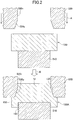
- FIG. 2 and FIG. 3 are diagrams illustrating an example of the manufacturing steps of the eyelet 10 according to the first embodiment.
- the step illustrated in FIG. 2 is a first processing step of preparing a metal member 100 having a plate shape (a disk shape, for example) and pressing the metal member 100 to form a first processed product 100A.
- the metal member 100 having a plate shape (a disk shape, for example) made of a metal material such as Kovar, iron, an iron-nickel alloy, or SUS is prepared, and the metal member 100 is placed on the upper surface of a die 510 that is a lower die. Because the die 510 has a cylindrical shape and has a diameter smaller than that of the metal member 100, the outer peripheral portion of the metal member 100 protrudes horizontally from the die 510.
- a punch 520 that is an upper die is lowered in the direction of the arrow A to apply pressure to (press) the metal member 100 placed on the upper surface of the die 510.
- the direction of the arrow A is a direction along the center line of the metal member 100, and is the vertical direction when the metal member 100 is horizontally placed.
- the punch 520 has a columnar opening portion 520x and a tapered opening portion 520y forming a part of a cone.
- the opening portion 520x and the opening portion 520y are concentrically formed in communication with each other.
- the maximum inner diameter (which is the inner diameter of the lowermost portion) of the opening portion 520y is smaller than the outer diameter of the metal member 100.
- the first processed product 100A is formed as illustrated in the part below the arrow B.
- the first processed product 100A is formed to have a cylindrical small diameter portion 12 having a first outer diameter, a cylindrical large diameter portion 150 having a second outer diameter larger than the first outer diameter, and a tapered portion 130 having a circular truncated cone shape and whose outer diameter gradually increases from the small diameter portion 12 toward the large diameter portion 150.
- the small diameter portion 12, the large diameter portion 150, and the tapered portion 130 are concentric.
- a cylindrical recessed portion 160 recessed toward the tapered portion 130 from the opposite side surface with respect to the tapered portion 130 is formed.
- the punch 520 having the tapered portion 520y can be used to press the metal member 100 such that the tapered portion 130 of the first processed product 100A is formed by the tapered portion 520y of the punch 510.
- the step illustrated in FIG. 3 is a second processing step of removing an outer peripheral portion of the first processed product 100A by shaving to form a second processed product (a trimming step of removing unnecessary portions).
- the first processed product 100A for which the step of FIG. 2 has been completed, is placed on a cylindrical punch 550 that is a lower die such that the bottom surface of the recessed portion 160 is supported. Because the outer diameter of the punch 550 is smaller than the inner diameter of the recessed portion 160, a clearance is present between the side wall of the punch 550 and the inner wall of the recessed portion 160.
- a die 560 that is an upper die is lowered in the direction of the arrow A to apply pressure to (press) the first processed product 100A arranged on the upper surface of the punch 550.
- the direction of the arrow A is a direction along the center line of the first processed product 100A, and is the vertical direction when the first processed product 100A is horizontally placed.
- the die 560 has a columnar opening portion 560x.
- the inner diameter of the opening portion 560x is larger than the outer diameter of the small diameter portion 12 and smaller than the outer diameter of the large diameter portion 150.
- the large diameter portion 11, the small diameter portion 12, the tapered portion 13, the large diameter portion 150, and the recessed portion 160 are formed on the first processed product 100A.
- the large diameter portion 11 and the tapered portion 13 are formed by cutting (shaving) an area outside a portion of the inclined surface of the tapered portion 130 in the direction along the arrow A.
- the first processed product 100A is cut such that the inclined surface of the tapered portion 130 partially remains in the second processed product.
- the large diameter portion 150 and the recessed portion 160 located in an area outside a portion of the inclined surface of the tapered portion 130 are cut, in a tearing manner, along the direction of the arrow A.
- the tapered portion 14 (see FIG. 1 ) is formed.
- the eyelet 10 illustrated in FIG. 1 is completed.
- the outer peripheral surfaces of the large diameter portion 11, the small diameter portion 12, and the tapered portion 13 are shear surfaces, and the outer peripheral surface of the tapered portion 14 is a fracture surface.
- FIGS. 4 and 5 are diagrams illustrating an example of steps of manufacturing an eyelet according to a comparative example.
- the step illustrated in FIG. 4 is a first processing step, but unlike FIG. 2 , a metal member 100 is pressed by using a punch 620, having only a cylindrical opening portion 620x, and a die 510 similar to that in FIG. 2 .
- the inner diameter of the opening portion 620x is smaller than the outer diameter of the metal member 100.
- the punch 620 that is an upper die is lowered in the direction of the arrow A to press the metal member 100 placed on the upper surface of the die 510.
- a small diameter portion 120A, a large diameter portion 150 having an outer diameter larger than that of the small diameter portion 120A, and a recessed portion 160 are formed, and a tapered portion is not formed.
- the step illustrated in FIG. 5 is a second processing step, which is basically the same as the step illustrated in FIG. 3 .
- the shape of the first processed product 100B to be processed differs from that in FIG. 3 .
- the inner diameter of the opening portion 560x is smaller than the outer diameter of the small diameter portion 120A.
- the die 560 that is an upper die in the direction of the arrow A to press the first processed product 100B arranged on the upper surface of the punch 550 upon lowering the die 560 that is an upper die in the direction of the arrow A to press the first processed product 100B arranged on the upper surface of the punch 550, the outer peripheral area of the cylindrical small diameter portion 120A is shaved from an upper surface 125, and a columnar small diameter portion 120B is formed.
- the large diameter portion 150 and the recessed portion 160 located in an area outside with respect to a predetermined diameter of the small diameter portion 120B are cut, in a tearing manner, along the direction of the arrow A.
- an eyelet according to the comparative example is completed.
- the shaved area portion removed in the second processing step
- the shaving becomes unstable when the shaving approaches the end. As a result, in the latter part of shaving, a shear surface cannot be formed.
- the tapered portion 130 is formed on the metal member 100 by pressing in the first processing step illustrated in FIG. 2 . Then, in the second processing step illustrated in FIG. 3 , an area outside a portion of the inclined surface of the tapered portion 130 is cut in the direction along the center line of the first processed product 100A.
- the shaved area is small at the starting position of the inclined surface of the tapered portion 130, suitable shaving is possible. Also, because the shaved area gradually increases, shaving does not become unstable even when the shaving approaches the end, and stable shaving is possible up to the end. As a result, a shear surface can be made larger than that of the comparative example. Also, because stable shaving is possible up to the end, occurrence of burrs can be reduced.
- the method of manufacturing the eyelet according to the present embodiment is particularly effective in that a shear surface can be increased.
- a step such as a step of forming a through hole on the first processed product by punching may be added.
- FIG. 6 and FIG. 7 are diagrams illustrating an example of the manufacturing steps of the eyelet according to the variation example 1 of the first embodiment.
- the step illustrated in FIG. 6 is a first processing step of preparing a metal member 100 having a plate shape (a disk shape, for example) and pressing the metal member 100 to form a first processed product 100C, and differs, from that in FIG. 2 , in that the die 510 is replaced with a die 530. Because the die 530 has a cylindrical shape and is larger in diameter than the metal member 100, the outer peripheral portion of the upper surface of the die 530 is exposed around the metal member 100.
- the first processed product 100C Upon pressing the metal member 100 by the die 530 and the punch 520 having the above-described shapes, as illustrated in the part below the arrow B, the first processed product 100C is formed.
- the first processed product 100C is formed to have a cylindrical small diameter portion 12 having a first outer diameter, a cylindrical large diameter portion 150 having a second outer diameter larger than the first outer diameter, and a tapered portion 130 having a circular truncated cone shape and whose outer diameter gradually increases from the small outer diameter portion 12 toward the large outer diameter portion 150.
- the small diameter portion 12, the large diameter portion 150, and the tapered portion 130 are concentric. Note that a recessed portion 160 as illustrated in FIG. 2 is not formed on the first processed product 100C.
- the step illustrated in FIG. 7 is a second processing step of removing an outer peripheral portion of the first processed product 100C by shaving to form a second processed product (a trimming step of removing unnecessary portions).
- the step illustrated in FIG. 7 is basically the same as the step illustrated in FIG. 3 , as illustrated in the part above the arrow B, the object to be processed is changed from the first processed product 100A to the first processed product 100C.
- the outer edge portion on the lower end side of the opening portion 560x contacts a portion of the inclined surface of the tapered portion 130.
- the large diameter portion 11, the small diameter portion 12, the tapered portion 13, and the large diameter portion 150 are formed on the first processed product 100C.
- the large diameter portion 150 located in an area outside a portion of the inclined surface of the tapered portion 130 is cut, in a tearing manner, along the direction of the arrow A.
- the tapered portion 14 (see FIG. 1 ) is formed.
- the eyelet 10 illustrated in FIG. 1 is completed.
- the outer peripheral surfaces of the large diameter portion 11, the small diameter portion 12, and the tapered portion 13 are shear surfaces, and the outer peripheral surface of the tapered portion 14 is a fracture surface.
- the die 530 having a diameter larger than that of the metal member 100 may be used.
- the thickness of the large diameter portion 150 of the first processed product 100C can be made thinner than that of the large diameter portion 150 of the first processed product 100A.
- the fracture surface can be further reduced and the shear surface can be further increased.
- the first embodiment is preferable in that the processing load is small and processing is easy in the first processing step.
- FIG. 8 is a diagram illustrating an example of the light emitting device 1 according to the second embodiment.
- FIG. 8 (a) is a plan view of the light emitting device 1
- FIG. 8 (b) is a cross-sectional view of the light emitting device 1 taken along the line B-B of FIG. 8 (a) .
- the light emitting device 1 includes the eyelet 10, a light emitting element 20, a lead 30, sealing portions 40, metal wires 50, a cap 60, and a transparent member 70.
- the light emitting device 1 can be used for, for example, an optical disk device, an optical communication device, or the like. Note that, in FIG. 8 (a) , illustration of the cap 60 and the transparent member 70 are omitted.
- the light emitting element 20 is, for example, a semiconductor laser chip with a wavelength of 780 nm and is mounted on the upper surface of the eyelet 10 in a state of being insulated from the eyelet 10.
- the lead 30 includes a first lead 31, a second lead 32, and a third lead 33.
- the first lead 31 and the third lead 33 are inserted into through holes 10x penetrating the eyelet 10 in the thickness direction such that their longitudinal directions are directed in the thickness direction, and their outer peripheries are sealed by the sealing portions 40.
- Parts of the first lead 31 and the third lead 33 protrude downward from the lower surface of the eyelet 10.
- the amounts of protrusion of the first lead 31 and the third lead 33 from the lower surface of the eyelet 10 may be, for example, approximately 6 mm to 7 mm.
- the first lead 31 and the third lead 33 are made of a metal such as Kovar or an iron-nickel alloy, for example.
- the sealing portions 40 are made of an insulating material such as a glass material, for example.
- the first lead 31 and the third lead 33 are electrically connected to the light emitting element 20.
- the light emitting device 1 may include a lead that is electrically connected to the light receiving element. Also, the number of leads connected to the light emitting element and the light receiving element may be further increased.
- the second lead 32 is joined to the lower surface of the eyelet 10 by welding or the like such that its longitudinal direction is directed in the thickness direction to protrude downward from the lower surface of the eyelet 10.
- the second lead 32 is made of a metal such as Kovar or an iron-nickel alloy, for example, and is used for grounding, for example. Note that the second lead 32 is joined so as to be electrically connected to the eyelet 10, and upon the second lead 32 being grounded, the eyelet 10 is also grounded.
- Electrodes (not illustrated) of the light emitting element 20 are connected to upper ends of the first lead 31 and the third lead 33, through the metal wires 50 such as gold wires or copper wires.
- the electrodes of the light emitting element 20, the first lead 31, and the third lead 33 can be connected through, for example, wire bonding.
- the cap 60 is made of, for example, a metal such as iron or copper.
- the transparent member 70 (window) is provided substantially at the center of the cap 60 in plan view.
- the transparent member 70 is made of glass or the like, for example, and is bonded to the cap 60 by an adhesive (not illustrated) made of low melting point glass or the like.
- the cap 60 is joined to the outer peripheral surface of the large diameter portion 11 of the eyelet 10 by, for example, welding or the like, and hermetically seals the light emitting element 20. Light emitted from the light emitting element 20 is emitted passing through the transparent member 70.
- the cap 60 is joined to the outer peripheral surface of the large diameter portion 11 of the eyelet 10 by welding or the like. Because the eyelet 10 is manufactured by the manufacturing method described in the first embodiment or the variation example 1 of the first embodiment, the outer peripheral surface of the large diameter portion 11 is a relatively large shear surface. Therefore, because the contact area between the smooth surface of the eyelet 10 and the cap 60 is increased, the reliability of their joint can be enhanced.
- the eyelet 10 is not limited to this, and may be used for various sensors, inflators, or the like.
Landscapes
- Engineering & Computer Science (AREA)
- Mechanical Engineering (AREA)
- Punching Or Piercing (AREA)
- Forging (AREA)
Abstract
Description
- The embodiments discussed herein relate to a method of manufacturing an eyelet.
- A metal eyelet is used, for example, in a light emitting device including a laser diode. In such a light emitting device, an eyelet is generally in a disk shape, and a laser diode is mounted on the eyelet, and a heat sink or the like is provided as needed. Also, a lead electrically insulated from the eyelet and electrically connected to the laser diode is provided. Eyelets may be used for products other than light emitting devices.
- For manufacturing an eyelet, for example, a metal member having a plate shape is prepared, the metal member is pressed to form a first processed product, and the outer peripheral portion of the first processed product is removed by shaving to form a second processed product. Also, a thorough hole is formed as needed.
- In the method of manufacturing the eyelet described above, the first processed product is formed to have a disk-shaped portion having a smaller diameter than that of the metal member before being processed. Then, the disc-shaped portion having the small diameter is shaved from the outer peripheral portion of the upper surface in a direction perpendicular to the upper surface to form the second processed product. A shear surface and a fracture surface are formed on the outer peripheral surface of the eyelet, which is the second processed product. In order to enhance the reliability of their joint with a member such as a cap joined to the outer peripheral surface of the eyelet, it is preferable for the shear surface to be longer.
- However, in the method of manufacturing the eyelet described above, because stresses in forming the second processed product readily occur in stretching directions, the fracture surface readily forms on the outer peripheral surface of the second processed product, which makes it difficult to make the shear surface longer.
- In view of the above, an object in one aspect of the embodiments is to provide a method of manufacturing an eyelet that can increase a shear surface of an outer peripheral surface.
- [Patent Document 1] International Publication Pamphlet No.
WO 2015/113746 - According to an aspect of the embodiments, a method of manufacturing an eyelet includes: a first processing step of preparing a metal member having a plate shape and pressing the metal member to form a first processed product; and a second processing step of removing an outer peripheral portion of the first processed product by shaving to form a second processed product, wherein, in the first processing step, the first processed product is formed to have a first outer diameter portion having a first outer diameter, a second outer diameter portion having a second outer diameter larger than the first outer diameter, and a tapered portion whose outer diameter gradually increases from the first outer diameter portion toward the second outer diameter portion, the first outer diameter portion, the second outer diameter portion, and the tapered portion being concentric and wherein, in the second processing step, an area outside a portion of an inclined surface of the tapered portion is cut in a direction from the first outer diameter portion toward the second outer diameter portion along a center line of the first processed product.
-
-
FIG. 1 is a diagram illustrating an example of an eyelet according to a first embodiment; -
FIG. 2 is a diagram illustrating an example of a step of manufacturing the eyelet according to the first embodiment (part 1); -
FIG. 3 is a diagram illustrating an example of a step of manufacturing the eyelet according to the first embodiment (part 2); -
FIG. 4 is a diagram illustrating an example of a step of manufacturing an eyelet according to a comparative example (part 1); -
FIG. 5 is a diagram illustrating an example of a step of manufacturing the eyelet according to the comparative example (part 2); -
FIG. 6 is a diagram illustrating an example of a step of manufacturing the eyelet according to a variation example 1 of the first embodiment (part 1); -
FIG. 7 is a diagram illustrating an example of a step of manufacturing the eyelet according to the variation example 1 of the first embodiment (part 2); and -
FIG. 8 is a diagram illustrating an example of a light emitting device according to a second embodiment. - In the following, embodiments will be described with reference to the accompanying drawings. In these drawings, the same elements are referred to by the same references, and duplicate descriptions may be omitted as appropriate.
- First, a structure of an
eyelet 10 according to a first embodiment will be described.FIG. 1 is a diagram illustrating an example of theeyelet 10 according to the first embodiment.FIG. 1 (a) is a plan view of theeyelet 10, andFIG. 1 (b) is a cross-sectional view of theeyelet 10 taken along the line A-A ofFIG. 1 (a) . - With reference to
FIG. 1 , theeyelet 10 according to the first embodiment is a member having a disk shape, and has alarge diameter portion 11, asmall diameter portion 12, atapered portion 13, and atapered portion 14. Thetapered portion 13 and thesmall diameter portion 12 are sequentially located on one side of thelarge diameter portion 11, and thetapered portion 14 is located on the other side of thelarge diameter portion 11. For example, thelarge diameter portion 11, thesmall diameter portion 12, and thetapered portions eyelet 10 may be provided with a through hole penetrating theeyelet 10 in the thickness direction. - Note that in the present application, the "disc shape" refers to one whose planar shape is a substantially circular shape and having a predetermined thickness. The size of the thickness with respect to the diameter is not limited. Also, one on which a recess, a protrusion, or the like is partially formed may be included as the "disc shape".
- The maximum outer diameter of the eyelet 10 (which is the diameter of the large diameter portion 11) is not particularly limited and can be determined as appropriate according to the purpose. For example, the maximum outer diameter of the
eyelet 10 may be approximately ϕ 5.6 mm. The thickness of theeyelet 10 is not particularly limited and can be determined as appropriate according to the purpose. For example, the thickness of theeyelet 10 may be approximately in a range of 1.0 mm to 5.0 mm. - The
eyelet 10 can be made of a metal material such as Kovar (which is a nickel-cobalt ferrous alloy), iron, an iron-nickel alloy, or SUS (stainless steel), for example. A plating process may be applied to the surface of theeyelet 10. - In the
eyelet 10, the outer peripheral surfaces of thelarge diameter portion 11, thesmall diameter portion 12, and thetapered portion 13 are shear surfaces, and the outer peripheral surface of thetapered portion 14 is a fracture surface. Here, a shear surface is a smooth surface cut and punched by the cutting edge of a die for pressing, and a diameter that is practically as designed can be obtained. Also, a fracture surface is a rough surface cut, in a tearing manner, by a material pushed by the cutting edge of a die for pressing, and a diameter that is as designed cannot be obtained. - A cap (which will be described later below) is joined to the outer peripheral surface of the
eyelet 10 by, for example, laser welding or the like. In such a case, for a longer shear surface, the contact area between the smooth surface of theeyelet 10 and the cap increases accordingly, thus, the reliability of their joint is enhanced. Therefore, for theeyelet 10, a manufacturing method is devised so as to increase (lengthen), on the outer peripheral surface, the shear surface to be as long as possible. - Next, a method of manufacturing the
eyelet 10 according to the first embodiment will be described.FIG. 2 andFIG. 3 are diagrams illustrating an example of the manufacturing steps of theeyelet 10 according to the first embodiment. - The step illustrated in
FIG. 2 is a first processing step of preparing ametal member 100 having a plate shape (a disk shape, for example) and pressing themetal member 100 to form a first processedproduct 100A. - First, as illustrated in the part above the arrow B, the
metal member 100 having a plate shape (a disk shape, for example) made of a metal material such as Kovar, iron, an iron-nickel alloy, or SUS is prepared, and themetal member 100 is placed on the upper surface of adie 510 that is a lower die. Because thedie 510 has a cylindrical shape and has a diameter smaller than that of themetal member 100, the outer peripheral portion of themetal member 100 protrudes horizontally from thedie 510. - Next, as illustrated in the part below the arrow B, a
punch 520 that is an upper die is lowered in the direction of the arrow A to apply pressure to (press) themetal member 100 placed on the upper surface of thedie 510. Note that the direction of the arrow A is a direction along the center line of themetal member 100, and is the vertical direction when themetal member 100 is horizontally placed. - The
punch 520 has acolumnar opening portion 520x and a tapered openingportion 520y forming a part of a cone. Theopening portion 520x and theopening portion 520y are concentrically formed in communication with each other. The maximum inner diameter (which is the inner diameter of the lowermost portion) of theopening portion 520y is smaller than the outer diameter of themetal member 100. - Upon the
metal member 100 being pressed (half-cut) by thedie 510 and thepunch 520 having the above-described shapes, the first processedproduct 100A is formed as illustrated in the part below the arrow B. The first processedproduct 100A is formed to have a cylindricalsmall diameter portion 12 having a first outer diameter, a cylindricallarge diameter portion 150 having a second outer diameter larger than the first outer diameter, and atapered portion 130 having a circular truncated cone shape and whose outer diameter gradually increases from thesmall diameter portion 12 toward thelarge diameter portion 150. Thesmall diameter portion 12, thelarge diameter portion 150, and the taperedportion 130 are concentric. Also, on thelarge diameter portion 150, a cylindrical recessedportion 160 recessed toward the taperedportion 130 from the opposite side surface with respect to the taperedportion 130 is formed. - As illustrated in
FIG. 2 , in the first processing step, thepunch 520 having the taperedportion 520y can be used to press themetal member 100 such that the taperedportion 130 of the first processedproduct 100A is formed by the taperedportion 520y of thepunch 510. - Next, the step illustrated in
FIG. 3 is a second processing step of removing an outer peripheral portion of the first processedproduct 100A by shaving to form a second processed product (a trimming step of removing unnecessary portions). - First, as illustrated in the part above the arrow B, the first processed
product 100A, for which the step ofFIG. 2 has been completed, is placed on acylindrical punch 550 that is a lower die such that the bottom surface of the recessedportion 160 is supported. Because the outer diameter of thepunch 550 is smaller than the inner diameter of the recessedportion 160, a clearance is present between the side wall of thepunch 550 and the inner wall of the recessedportion 160. - Next, as illustrated in the part below the arrow B, a
die 560 that is an upper die is lowered in the direction of the arrow A to apply pressure to (press) the first processedproduct 100A arranged on the upper surface of thepunch 550. Note that the direction of the arrow A is a direction along the center line of the first processedproduct 100A, and is the vertical direction when the first processedproduct 100A is horizontally placed. - The
die 560 has acolumnar opening portion 560x. The inner diameter of theopening portion 560x is larger than the outer diameter of thesmall diameter portion 12 and smaller than the outer diameter of thelarge diameter portion 150. Upon lowering thedie 560 in the direction of the arrow A, the outer edge portion on the lower end side of theopening portion 560x contacts a portion of the inclined surface of the taperedportion 130. - Upon lowering the
die 560 in the direction of the arrow A by using thepunch 550 and thedie 560 having the above-described shapes, as illustrated in the part below the arrow B, thelarge diameter portion 11, thesmall diameter portion 12, the taperedportion 13, thelarge diameter portion 150, and the recessedportion 160 are formed on the first processedproduct 100A. Thelarge diameter portion 11 and the taperedportion 13 are formed by cutting (shaving) an area outside a portion of the inclined surface of the taperedportion 130 in the direction along the arrow A. - As illustrated in
FIG. 3 , in the second processing step, the first processedproduct 100A is cut such that the inclined surface of the taperedportion 130 partially remains in the second processed product. - By further lowering the
die 560 in the direction of the arrow A from the state illustrated in the part below the arrow B, thelarge diameter portion 150 and the recessedportion 160 located in an area outside a portion of the inclined surface of the taperedportion 130 are cut, in a tearing manner, along the direction of the arrow A. As a result, the tapered portion 14 (seeFIG. 1 ) is formed. Thereby, theeyelet 10 illustrated inFIG. 1 is completed. In the completedeyelet 10, the outer peripheral surfaces of thelarge diameter portion 11, thesmall diameter portion 12, and the taperedportion 13 are shear surfaces, and the outer peripheral surface of the taperedportion 14 is a fracture surface. -
FIGS. 4 and5 are diagrams illustrating an example of steps of manufacturing an eyelet according to a comparative example. The step illustrated inFIG. 4 is a first processing step, but unlikeFIG. 2 , ametal member 100 is pressed by using apunch 620, having only acylindrical opening portion 620x, and a die 510 similar to that inFIG. 2 . The inner diameter of theopening portion 620x is smaller than the outer diameter of themetal member 100. - Next, as illustrated in the part below the arrow B in
FIG. 4 , thepunch 620 that is an upper die is lowered in the direction of the arrow A to press themetal member 100 placed on the upper surface of thedie 510. Thereby, on the first processedproduct 100B, asmall diameter portion 120A, alarge diameter portion 150 having an outer diameter larger than that of thesmall diameter portion 120A, and a recessedportion 160 are formed, and a tapered portion is not formed. - Next, the step illustrated in
FIG. 5 is a second processing step, which is basically the same as the step illustrated inFIG. 3 . However, the shape of the first processedproduct 100B to be processed differs from that inFIG. 3 . The inner diameter of theopening portion 560x is smaller than the outer diameter of thesmall diameter portion 120A. - As illustrated in the part below the arrow B, upon lowering the
die 560 that is an upper die in the direction of the arrow A to press the first processedproduct 100B arranged on the upper surface of thepunch 550, the outer peripheral area of the cylindricalsmall diameter portion 120A is shaved from anupper surface 125, and a columnarsmall diameter portion 120B is formed. By further lowering thedie 560 in the direction of the arrow A from the state illustrated in the part below the arrow B, thelarge diameter portion 150 and the recessedportion 160 located in an area outside with respect to a predetermined diameter of thesmall diameter portion 120B are cut, in a tearing manner, along the direction of the arrow A. As a result, an eyelet according to the comparative example is completed. - In order to increase the shear surface, it is better for the shaved area (portion removed in the second processing step) to be small at the start of shaving. If the shaved area is small, and if the shaved area is continuously constant as in the comparative example, the shaving becomes unstable when the shaving approaches the end. As a result, in the latter part of shaving, a shear surface cannot be formed.
- Conversely, in the method of manufacturing the eyelet according to the present embodiment, unlike the method of manufacturing the eyelet according to the comparative example, the tapered
portion 130 is formed on themetal member 100 by pressing in the first processing step illustrated inFIG. 2 . Then, in the second processing step illustrated inFIG. 3 , an area outside a portion of the inclined surface of the taperedportion 130 is cut in the direction along the center line of the first processedproduct 100A. - According to the method of manufacturing the eyelet according to the present embodiment, because the shaved area is small at the starting position of the inclined surface of the tapered
portion 130, suitable shaving is possible. Also, because the shaved area gradually increases, shaving does not become unstable even when the shaving approaches the end, and stable shaving is possible up to the end. As a result, a shear surface can be made larger than that of the comparative example. Also, because stable shaving is possible up to the end, occurrence of burrs can be reduced. - In a case where SUS is used as the material of the
eyelet 10, it is difficult to increase the shear surface on SUS as compared to iron or the like. Therefore, in a case where SUS is used as the material of theeyelet 10, the method of manufacturing the eyelet according to the present embodiment is particularly effective in that a shear surface can be increased. - Note that, between the first processing step and the second processing step, a step such as a step of forming a through hole on the first processed product by punching may be added.
- A method of manufacturing an eyelet according to a variation example 1 of the first embodiment different from that of the first embodiment will be described. Note that in the variation example 1 of the first embodiment, descriptions of constituent elements the same as or similar to those of the previously provided descriptions may be omitted as appropriate.
-
FIG. 6 andFIG. 7 are diagrams illustrating an example of the manufacturing steps of the eyelet according to the variation example 1 of the first embodiment. - The step illustrated in
FIG. 6 is a first processing step of preparing ametal member 100 having a plate shape (a disk shape, for example) and pressing themetal member 100 to form a first processedproduct 100C, and differs, from that inFIG. 2 , in that thedie 510 is replaced with adie 530. Because thedie 530 has a cylindrical shape and is larger in diameter than themetal member 100, the outer peripheral portion of the upper surface of thedie 530 is exposed around themetal member 100. - Upon pressing the
metal member 100 by thedie 530 and thepunch 520 having the above-described shapes, as illustrated in the part below the arrow B, the first processedproduct 100C is formed. The first processedproduct 100C is formed to have a cylindricalsmall diameter portion 12 having a first outer diameter, a cylindricallarge diameter portion 150 having a second outer diameter larger than the first outer diameter, and atapered portion 130 having a circular truncated cone shape and whose outer diameter gradually increases from the smallouter diameter portion 12 toward the largeouter diameter portion 150. Thesmall diameter portion 12, thelarge diameter portion 150, and the taperedportion 130 are concentric. Note that a recessedportion 160 as illustrated inFIG. 2 is not formed on the first processedproduct 100C. - Next, the step illustrated in
FIG. 7 is a second processing step of removing an outer peripheral portion of the first processedproduct 100C by shaving to form a second processed product (a trimming step of removing unnecessary portions). Although the step illustrated inFIG. 7 is basically the same as the step illustrated inFIG. 3 , as illustrated in the part above the arrow B, the object to be processed is changed from the first processedproduct 100A to the first processedproduct 100C. - Upon placing the first processed
product 100C on thepunch 550 such that the bottom surface of thelarge diameter portion 150 is supported and lowering thedie 560 in the direction of the arrow A, as illustrated in the part below the arrow B, the outer edge portion on the lower end side of theopening portion 560x contacts a portion of the inclined surface of the taperedportion 130. Thereby, similarly toFIG. 3 , thelarge diameter portion 11, thesmall diameter portion 12, the taperedportion 13, and thelarge diameter portion 150 are formed on the first processedproduct 100C. - By further lowering the
die 560 in the direction of the arrow A from the state illustrated in the part below the arrow B, thelarge diameter portion 150 located in an area outside a portion of the inclined surface of the taperedportion 130 is cut, in a tearing manner, along the direction of the arrow A. As a result, the tapered portion 14 (seeFIG. 1 ) is formed. Thereby, theeyelet 10 illustrated inFIG. 1 is completed. In the completedeyelet 10, the outer peripheral surfaces of thelarge diameter portion 11, thesmall diameter portion 12, and the taperedportion 13 are shear surfaces, and the outer peripheral surface of the taperedportion 14 is a fracture surface. - In this manner, in the first processing step, the
die 530 having a diameter larger than that of themetal member 100 may be used. In this case, although the processing load in the first processing step increases, the thickness of thelarge diameter portion 150 of the first processedproduct 100C can be made thinner than that of thelarge diameter portion 150 of the first processedproduct 100A. As a result, because thelarge diameter portion 150 can be easily removed in the second processing step, the fracture surface can be further reduced and the shear surface can be further increased. - Note that in the first processed
product 100A according to the first embodiment, although the thickness of thelarge diameter portion 150 is thicker than that of the first processedproduct 100C, the first embodiment is preferable in that the processing load is small and processing is easy in the first processing step. - In a second embodiment, an example of a
light emitting device 1 using theeyelet 10 according to the first embodiment will be described. Note that in the second embodiment, descriptions of constituent elements the same as or similar to those of the previously provided descriptions may be omitted as appropriate. -
FIG. 8 is a diagram illustrating an example of thelight emitting device 1 according to the second embodiment.FIG. 8 (a) is a plan view of thelight emitting device 1, andFIG. 8 (b) is a cross-sectional view of thelight emitting device 1 taken along the line B-B ofFIG. 8 (a) . - With reference to
FIG. 8 , thelight emitting device 1 includes theeyelet 10, alight emitting element 20, alead 30, sealingportions 40,metal wires 50, acap 60, and atransparent member 70. Thelight emitting device 1 can be used for, for example, an optical disk device, an optical communication device, or the like. Note that, inFIG. 8 (a) , illustration of thecap 60 and thetransparent member 70 are omitted. - The
light emitting element 20 is, for example, a semiconductor laser chip with a wavelength of 780 nm and is mounted on the upper surface of theeyelet 10 in a state of being insulated from theeyelet 10. - The
lead 30 includes afirst lead 31, asecond lead 32, and athird lead 33. Thefirst lead 31 and thethird lead 33 are inserted into throughholes 10x penetrating theeyelet 10 in the thickness direction such that their longitudinal directions are directed in the thickness direction, and their outer peripheries are sealed by the sealingportions 40. Parts of thefirst lead 31 and thethird lead 33 protrude downward from the lower surface of theeyelet 10. The amounts of protrusion of thefirst lead 31 and thethird lead 33 from the lower surface of theeyelet 10 may be, for example, approximately 6 mm to 7 mm. - The
first lead 31 and thethird lead 33 are made of a metal such as Kovar or an iron-nickel alloy, for example. The sealingportions 40 are made of an insulating material such as a glass material, for example. Thefirst lead 31 and thethird lead 33 are electrically connected to thelight emitting element 20. In a case where a light receiving element is also mounted on thelight emitting device 1, thelight emitting device 1 may include a lead that is electrically connected to the light receiving element. Also, the number of leads connected to the light emitting element and the light receiving element may be further increased. - The
second lead 32 is joined to the lower surface of theeyelet 10 by welding or the like such that its longitudinal direction is directed in the thickness direction to protrude downward from the lower surface of theeyelet 10. Thesecond lead 32 is made of a metal such as Kovar or an iron-nickel alloy, for example, and is used for grounding, for example. Note that thesecond lead 32 is joined so as to be electrically connected to theeyelet 10, and upon thesecond lead 32 being grounded, theeyelet 10 is also grounded. - Electrodes (not illustrated) of the
light emitting element 20 are connected to upper ends of thefirst lead 31 and thethird lead 33, through themetal wires 50 such as gold wires or copper wires. The electrodes of thelight emitting element 20, thefirst lead 31, and thethird lead 33 can be connected through, for example, wire bonding. - The
cap 60 is made of, for example, a metal such as iron or copper. The transparent member 70 (window) is provided substantially at the center of thecap 60 in plan view. Thetransparent member 70 is made of glass or the like, for example, and is bonded to thecap 60 by an adhesive (not illustrated) made of low melting point glass or the like. Thecap 60 is joined to the outer peripheral surface of thelarge diameter portion 11 of theeyelet 10 by, for example, welding or the like, and hermetically seals thelight emitting element 20. Light emitted from thelight emitting element 20 is emitted passing through thetransparent member 70. - In this manner, in the
light emitting device 1, thecap 60 is joined to the outer peripheral surface of thelarge diameter portion 11 of theeyelet 10 by welding or the like. Because theeyelet 10 is manufactured by the manufacturing method described in the first embodiment or the variation example 1 of the first embodiment, the outer peripheral surface of thelarge diameter portion 11 is a relatively large shear surface. Therefore, because the contact area between the smooth surface of theeyelet 10 and thecap 60 is increased, the reliability of their joint can be enhanced. - According to the disclosed technique, it is possible to provide a method of manufacturing an eyelet that can increase a shear surface of an outer peripheral surface.
- Further, although the preferred embodiments and the variation example have been described above in detail, the present invention is not limited to these embodiments and the variation example, and various variations and modifications may be made without departing from the scope of the present invention.
- For example, although an example in which the
eyelet 10 is used for thelight emitting device 1 is described in the second embodiment, theeyelet 10 is not limited to this, and may be used for various sensors, inflators, or the like.
Claims (6)
- A method of manufacturing an eyelet (10), the method comprising:a first processing step of preparing a metal member (100) having a plate shape and pressing the metal member (100) to form a first processed product (100A, 100C); anda second processing step of removing an outer peripheral portion of the first processed product (100A, 100C) by shaving to form a second processed product,wherein, in the first processing step, the first processed product (100A, 100C) is formed to have a first outer diameter portion (12) having a first outer diameter, a second outer diameter portion (150) having a second outer diameter larger than the first outer diameter, and a tapered portion (130) whose outer diameter gradually increases from the first outer diameter portion (12) toward the second outer diameter portion (150), the first outer diameter portion (12), the second outer diameter portion (150), and the tapered portion (130) being concentric, andwherein, in the second processing step, an area outside a portion of an inclined surface of the tapered portion (130) is cut in a direction from the first outer diameter portion (12) toward the second outer diameter portion (150) along a center line of the first processed product (100A, 100C).
- The method of manufacturing the eyelet (10) according to claim 1,
wherein, in the first processing step, the first outer diameter portion (12) is formed in a cylindrical shape, and the second outer diameter portion (150) is formed in a cylindrical shape having a recessed portion (160) recessed toward the tapered portion (130) from an opposite side surface with respect to the tapered portion (130), and the tapered portion (130) is formed in a circular truncated cone shape, and
wherein, in the second processing step, the first processed product (100A, 100C) is placed on a die (550) such that a bottom surface of the recessed portion (160) is supported, and the first processed product (100A, 100C) is cut. - The method of manufacturing the eyelet (10) according to claim 1,
wherein, in the first processing step, the first outer diameter portion (12) and the second outer diameter portion (150) are formed in cylindrical shapes, and the tapered portion (130) is formed in a circular truncated cone shape, and
wherein, in the second processing step, the first processed product (100A, 100C) is placed on a die (550) such that a bottom surface of the second outer diameter portion (150) is supported, and the first processed product (100A, 100C) is cut. - The method of manufacturing the eyelet (10) according to any one of claims 1 to 3, wherein the metal member (100) is made of stainless steel.
- The method of manufacturing the eyelet (10) according to any one of claims 1 to 4,
wherein, in the first processing step, a punch (520) having a tapered portion (520y) is used to press the metal member (100) such that the tapered portion (130) of the first processed product (100A, 100C) is formed by the tapered portion (520y) of the punch (520). - The method of manufacturing the eyelet (10) according to any one of claims 1 to 5,
wherein, in the second processing step, the first processed product (100A, 100C) is cut such that the inclined surface of the tapered portion (130) partially remains in the second processed product.
Applications Claiming Priority (1)
| Application Number | Priority Date | Filing Date | Title |
|---|---|---|---|
| JP2017232161A JP6293350B1 (en) | 2017-12-01 | 2017-12-01 | Eyelet manufacturing method |
Publications (2)
| Publication Number | Publication Date |
|---|---|
| EP3492190A1 true EP3492190A1 (en) | 2019-06-05 |
| EP3492190B1 EP3492190B1 (en) | 2020-09-23 |
Family
ID=61628975
Family Applications (1)
| Application Number | Title | Priority Date | Filing Date |
|---|---|---|---|
| EP18201377.1A Active EP3492190B1 (en) | 2017-12-01 | 2018-10-19 | Method of manufacturing eyelet |
Country Status (2)
| Country | Link |
|---|---|
| EP (1) | EP3492190B1 (en) |
| JP (1) | JP6293350B1 (en) |
Cited By (1)
| Publication number | Priority date | Publication date | Assignee | Title |
|---|---|---|---|---|
| JP2020062669A (en) * | 2018-10-18 | 2020-04-23 | 新光電気工業株式会社 | Manufacturing method of eyelet |
Citations (2)
| Publication number | Priority date | Publication date | Assignee | Title |
|---|---|---|---|---|
| US3583266A (en) * | 1968-04-11 | 1971-06-08 | Kazuyoshi Kondo | Shearing process |
| WO2015113746A1 (en) | 2014-01-30 | 2015-08-06 | Electrovac Hacht & Huber Gmbh | Method for producing an igniter socket |
Family Cites Families (2)
| Publication number | Priority date | Publication date | Assignee | Title |
|---|---|---|---|---|
| JPH0810865A (en) * | 1994-06-22 | 1996-01-16 | Unai Kinzoku Kogyo Kk | Device for finishing circumferential face of press article and method therefor |
| JP5012365B2 (en) * | 2007-09-26 | 2012-08-29 | アイシン・エィ・ダブリュ株式会社 | Member having chamfered through hole and method for manufacturing the same |
-
2017
- 2017-12-01 JP JP2017232161A patent/JP6293350B1/en active Active
-
2018
- 2018-10-19 EP EP18201377.1A patent/EP3492190B1/en active Active
Patent Citations (2)
| Publication number | Priority date | Publication date | Assignee | Title |
|---|---|---|---|---|
| US3583266A (en) * | 1968-04-11 | 1971-06-08 | Kazuyoshi Kondo | Shearing process |
| WO2015113746A1 (en) | 2014-01-30 | 2015-08-06 | Electrovac Hacht & Huber Gmbh | Method for producing an igniter socket |
Cited By (1)
| Publication number | Priority date | Publication date | Assignee | Title |
|---|---|---|---|---|
| JP2020062669A (en) * | 2018-10-18 | 2020-04-23 | 新光電気工業株式会社 | Manufacturing method of eyelet |
Also Published As
| Publication number | Publication date |
|---|---|
| JP6293350B1 (en) | 2018-03-14 |
| JP2019098368A (en) | 2019-06-24 |
| EP3492190B1 (en) | 2020-09-23 |
Similar Documents
| Publication | Publication Date | Title |
|---|---|---|
| US4331740A (en) | Gang bonding interconnect tape process and structure for semiconductor device automatic assembly | |
| KR100611681B1 (en) | Semiconductor Laser Device | |
| CN102347424A (en) | Semiconductor device, lead frame assembly, and method for fabricating same | |
| US9842968B2 (en) | LED package | |
| JP2018515916A (en) | Apparatus comprising a substrate and a semiconductor laser | |
| US10164403B2 (en) | Cap member and light-emitting device | |
| EP3492190B1 (en) | Method of manufacturing eyelet | |
| JP2020113695A (en) | Stem for semiconductor package and semiconductor package | |
| EP3640974B1 (en) | Method of manufacturing eyelet | |
| EP3340377B1 (en) | Creating antennas connected to printed chips by post processing with a laser or other cutting device | |
| PH12018000306A1 (en) | Method for producing lead frame and lead frame | |
| EP3639944B1 (en) | Method of manufacturing eyelet | |
| CN101320886A (en) | Lidless package and manufacturing method thereof | |
| JP2010087173A (en) | Method of manufacturing semiconductor device, and semiconductor device | |
| US6649450B2 (en) | Method of producing an integrated circuit and an integrated circuit | |
| JP2023158054A (en) | Semiconductor device and its manufacturing method | |
| CN103579162A (en) | Lead frame assembly, lead frame and cutting method thereof | |
| EP4012754A1 (en) | Header for semiconductor package, semiconductor package, and method for manufacturing header for semiconductor package | |
| JP5347934B2 (en) | Mold package manufacturing method and mold package | |
| JP2001077262A (en) | Semiconductor device | |
| JP3553726B2 (en) | Cap for electronic parts, semiconductor laser using the same, and manufacturing method thereof | |
| CN105261694B (en) | L ED support and its production method | |
| JPH11251688A (en) | Cap for electronic part and semiconductor laser using the cap | |
| JP2011124283A (en) | Method of manufacturing mold package, and mold package | |
| CN109791842B (en) | Method for manufacturing lead terminal, chip type electrolytic capacitor, and semi-finished product of lead terminal |
Legal Events
| Date | Code | Title | Description |
|---|---|---|---|
| PUAI | Public reference made under article 153(3) epc to a published international application that has entered the european phase |
Free format text: ORIGINAL CODE: 0009012 |
|
| STAA | Information on the status of an ep patent application or granted ep patent |
Free format text: STATUS: THE APPLICATION HAS BEEN PUBLISHED |
|
| AK | Designated contracting states |
Kind code of ref document: A1 Designated state(s): AL AT BE BG CH CY CZ DE DK EE ES FI FR GB GR HR HU IE IS IT LI LT LU LV MC MK MT NL NO PL PT RO RS SE SI SK SM TR |
|
| AX | Request for extension of the european patent |
Extension state: BA ME |
|
| STAA | Information on the status of an ep patent application or granted ep patent |
Free format text: STATUS: REQUEST FOR EXAMINATION WAS MADE |
|
| 17P | Request for examination filed |
Effective date: 20190918 |
|
| RBV | Designated contracting states (corrected) |
Designated state(s): AL AT BE BG CH CY CZ DE DK EE ES FI FR GB GR HR HU IE IS IT LI LT LU LV MC MK MT NL NO PL PT RO RS SE SI SK SM TR |
|
| GRAP | Despatch of communication of intention to grant a patent |
Free format text: ORIGINAL CODE: EPIDOSNIGR1 |
|
| STAA | Information on the status of an ep patent application or granted ep patent |
Free format text: STATUS: GRANT OF PATENT IS INTENDED |
|
| RIC1 | Information provided on ipc code assigned before grant |
Ipc: B21D 28/16 20060101AFI20200326BHEP |
|
| INTG | Intention to grant announced |
Effective date: 20200428 |
|
| GRAS | Grant fee paid |
Free format text: ORIGINAL CODE: EPIDOSNIGR3 |
|
| GRAA | (expected) grant |
Free format text: ORIGINAL CODE: 0009210 |
|
| STAA | Information on the status of an ep patent application or granted ep patent |
Free format text: STATUS: THE PATENT HAS BEEN GRANTED |
|
| AK | Designated contracting states |
Kind code of ref document: B1 Designated state(s): AL AT BE BG CH CY CZ DE DK EE ES FI FR GB GR HR HU IE IS IT LI LT LU LV MC MK MT NL NO PL PT RO RS SE SI SK SM TR |
|
| REG | Reference to a national code |
Ref country code: GB Ref legal event code: FG4D |
|
| REG | Reference to a national code |
Ref country code: CH Ref legal event code: EP |
|
| REG | Reference to a national code |
Ref country code: IE Ref legal event code: FG4D |
|
| REG | Reference to a national code |
Ref country code: DE Ref legal event code: R096 Ref document number: 602018008063 Country of ref document: DE Ref country code: AT Ref legal event code: REF Ref document number: 1315867 Country of ref document: AT Kind code of ref document: T Effective date: 20201015 |
|
| PG25 | Lapsed in a contracting state [announced via postgrant information from national office to epo] |
Ref country code: FI Free format text: LAPSE BECAUSE OF FAILURE TO SUBMIT A TRANSLATION OF THE DESCRIPTION OR TO PAY THE FEE WITHIN THE PRESCRIBED TIME-LIMIT Effective date: 20200923 Ref country code: NO Free format text: LAPSE BECAUSE OF FAILURE TO SUBMIT A TRANSLATION OF THE DESCRIPTION OR TO PAY THE FEE WITHIN THE PRESCRIBED TIME-LIMIT Effective date: 20201223 Ref country code: SE Free format text: LAPSE BECAUSE OF FAILURE TO SUBMIT A TRANSLATION OF THE DESCRIPTION OR TO PAY THE FEE WITHIN THE PRESCRIBED TIME-LIMIT Effective date: 20200923 Ref country code: BG Free format text: LAPSE BECAUSE OF FAILURE TO SUBMIT A TRANSLATION OF THE DESCRIPTION OR TO PAY THE FEE WITHIN THE PRESCRIBED TIME-LIMIT Effective date: 20201223 Ref country code: GR Free format text: LAPSE BECAUSE OF FAILURE TO SUBMIT A TRANSLATION OF THE DESCRIPTION OR TO PAY THE FEE WITHIN THE PRESCRIBED TIME-LIMIT Effective date: 20201224 Ref country code: HR Free format text: LAPSE BECAUSE OF FAILURE TO SUBMIT A TRANSLATION OF THE DESCRIPTION OR TO PAY THE FEE WITHIN THE PRESCRIBED TIME-LIMIT Effective date: 20200923 |
|
| REG | Reference to a national code |
Ref country code: AT Ref legal event code: MK05 Ref document number: 1315867 Country of ref document: AT Kind code of ref document: T Effective date: 20200923 |
|
| PG25 | Lapsed in a contracting state [announced via postgrant information from national office to epo] |
Ref country code: RS Free format text: LAPSE BECAUSE OF FAILURE TO SUBMIT A TRANSLATION OF THE DESCRIPTION OR TO PAY THE FEE WITHIN THE PRESCRIBED TIME-LIMIT Effective date: 20200923 Ref country code: LV Free format text: LAPSE BECAUSE OF FAILURE TO SUBMIT A TRANSLATION OF THE DESCRIPTION OR TO PAY THE FEE WITHIN THE PRESCRIBED TIME-LIMIT Effective date: 20200923 |
|
| REG | Reference to a national code |
Ref country code: NL Ref legal event code: MP Effective date: 20200923 |
|
| REG | Reference to a national code |
Ref country code: LT Ref legal event code: MG4D |
|
| PG25 | Lapsed in a contracting state [announced via postgrant information from national office to epo] |
Ref country code: CZ Free format text: LAPSE BECAUSE OF FAILURE TO SUBMIT A TRANSLATION OF THE DESCRIPTION OR TO PAY THE FEE WITHIN THE PRESCRIBED TIME-LIMIT Effective date: 20200923 Ref country code: RO Free format text: LAPSE BECAUSE OF FAILURE TO SUBMIT A TRANSLATION OF THE DESCRIPTION OR TO PAY THE FEE WITHIN THE PRESCRIBED TIME-LIMIT Effective date: 20200923 Ref country code: PT Free format text: LAPSE BECAUSE OF FAILURE TO SUBMIT A TRANSLATION OF THE DESCRIPTION OR TO PAY THE FEE WITHIN THE PRESCRIBED TIME-LIMIT Effective date: 20210125 Ref country code: EE Free format text: LAPSE BECAUSE OF FAILURE TO SUBMIT A TRANSLATION OF THE DESCRIPTION OR TO PAY THE FEE WITHIN THE PRESCRIBED TIME-LIMIT Effective date: 20200923 Ref country code: SM Free format text: LAPSE BECAUSE OF FAILURE TO SUBMIT A TRANSLATION OF THE DESCRIPTION OR TO PAY THE FEE WITHIN THE PRESCRIBED TIME-LIMIT Effective date: 20200923 Ref country code: LT Free format text: LAPSE BECAUSE OF FAILURE TO SUBMIT A TRANSLATION OF THE DESCRIPTION OR TO PAY THE FEE WITHIN THE PRESCRIBED TIME-LIMIT Effective date: 20200923 |
|
| PG25 | Lapsed in a contracting state [announced via postgrant information from national office to epo] |
Ref country code: IS Free format text: LAPSE BECAUSE OF FAILURE TO SUBMIT A TRANSLATION OF THE DESCRIPTION OR TO PAY THE FEE WITHIN THE PRESCRIBED TIME-LIMIT Effective date: 20210123 Ref country code: PL Free format text: LAPSE BECAUSE OF FAILURE TO SUBMIT A TRANSLATION OF THE DESCRIPTION OR TO PAY THE FEE WITHIN THE PRESCRIBED TIME-LIMIT Effective date: 20200923 Ref country code: AL Free format text: LAPSE BECAUSE OF FAILURE TO SUBMIT A TRANSLATION OF THE DESCRIPTION OR TO PAY THE FEE WITHIN THE PRESCRIBED TIME-LIMIT Effective date: 20200923 Ref country code: AT Free format text: LAPSE BECAUSE OF FAILURE TO SUBMIT A TRANSLATION OF THE DESCRIPTION OR TO PAY THE FEE WITHIN THE PRESCRIBED TIME-LIMIT Effective date: 20200923 Ref country code: ES Free format text: LAPSE BECAUSE OF FAILURE TO SUBMIT A TRANSLATION OF THE DESCRIPTION OR TO PAY THE FEE WITHIN THE PRESCRIBED TIME-LIMIT Effective date: 20200923 |
|
| REG | Reference to a national code |
Ref country code: DE Ref legal event code: R097 Ref document number: 602018008063 Country of ref document: DE |
|
| PG25 | Lapsed in a contracting state [announced via postgrant information from national office to epo] |
Ref country code: MC Free format text: LAPSE BECAUSE OF FAILURE TO SUBMIT A TRANSLATION OF THE DESCRIPTION OR TO PAY THE FEE WITHIN THE PRESCRIBED TIME-LIMIT Effective date: 20200923 Ref country code: LU Free format text: LAPSE BECAUSE OF NON-PAYMENT OF DUE FEES Effective date: 20201019 Ref country code: SK Free format text: LAPSE BECAUSE OF FAILURE TO SUBMIT A TRANSLATION OF THE DESCRIPTION OR TO PAY THE FEE WITHIN THE PRESCRIBED TIME-LIMIT Effective date: 20200923 |
|
| REG | Reference to a national code |
Ref country code: BE Ref legal event code: MM Effective date: 20201031 |
|
| PLBE | No opposition filed within time limit |
Free format text: ORIGINAL CODE: 0009261 |
|
| STAA | Information on the status of an ep patent application or granted ep patent |
Free format text: STATUS: NO OPPOSITION FILED WITHIN TIME LIMIT |
|
| PG25 | Lapsed in a contracting state [announced via postgrant information from national office to epo] |
Ref country code: DK Free format text: LAPSE BECAUSE OF FAILURE TO SUBMIT A TRANSLATION OF THE DESCRIPTION OR TO PAY THE FEE WITHIN THE PRESCRIBED TIME-LIMIT Effective date: 20200923 Ref country code: SI Free format text: LAPSE BECAUSE OF FAILURE TO SUBMIT A TRANSLATION OF THE DESCRIPTION OR TO PAY THE FEE WITHIN THE PRESCRIBED TIME-LIMIT Effective date: 20200923 Ref country code: BE Free format text: LAPSE BECAUSE OF NON-PAYMENT OF DUE FEES Effective date: 20201031 |
|
| 26N | No opposition filed |
Effective date: 20210624 |
|
| PG25 | Lapsed in a contracting state [announced via postgrant information from national office to epo] |
Ref country code: IT Free format text: LAPSE BECAUSE OF FAILURE TO SUBMIT A TRANSLATION OF THE DESCRIPTION OR TO PAY THE FEE WITHIN THE PRESCRIBED TIME-LIMIT Effective date: 20200923 Ref country code: FR Free format text: LAPSE BECAUSE OF NON-PAYMENT OF DUE FEES Effective date: 20201123 Ref country code: IE Free format text: LAPSE BECAUSE OF NON-PAYMENT OF DUE FEES Effective date: 20201019 |
|
| PG25 | Lapsed in a contracting state [announced via postgrant information from national office to epo] |
Ref country code: TR Free format text: LAPSE BECAUSE OF FAILURE TO SUBMIT A TRANSLATION OF THE DESCRIPTION OR TO PAY THE FEE WITHIN THE PRESCRIBED TIME-LIMIT Effective date: 20200923 Ref country code: MT Free format text: LAPSE BECAUSE OF FAILURE TO SUBMIT A TRANSLATION OF THE DESCRIPTION OR TO PAY THE FEE WITHIN THE PRESCRIBED TIME-LIMIT Effective date: 20200923 Ref country code: CY Free format text: LAPSE BECAUSE OF FAILURE TO SUBMIT A TRANSLATION OF THE DESCRIPTION OR TO PAY THE FEE WITHIN THE PRESCRIBED TIME-LIMIT Effective date: 20200923 |
|
| REG | Reference to a national code |
Ref country code: CH Ref legal event code: PL |
|
| PG25 | Lapsed in a contracting state [announced via postgrant information from national office to epo] |
Ref country code: MK Free format text: LAPSE BECAUSE OF FAILURE TO SUBMIT A TRANSLATION OF THE DESCRIPTION OR TO PAY THE FEE WITHIN THE PRESCRIBED TIME-LIMIT Effective date: 20200923 |
|
| PG25 | Lapsed in a contracting state [announced via postgrant information from national office to epo] |
Ref country code: LI Free format text: LAPSE BECAUSE OF NON-PAYMENT OF DUE FEES Effective date: 20211031 Ref country code: CH Free format text: LAPSE BECAUSE OF NON-PAYMENT OF DUE FEES Effective date: 20211031 |
|
| GBPC | Gb: european patent ceased through non-payment of renewal fee |
Effective date: 20221019 |
|
| PG25 | Lapsed in a contracting state [announced via postgrant information from national office to epo] |
Ref country code: NL Free format text: LAPSE BECAUSE OF NON-PAYMENT OF DUE FEES Effective date: 20200923 |
|
| PG25 | Lapsed in a contracting state [announced via postgrant information from national office to epo] |
Ref country code: GB Free format text: LAPSE BECAUSE OF NON-PAYMENT OF DUE FEES Effective date: 20221019 |
|
| PGFP | Annual fee paid to national office [announced via postgrant information from national office to epo] |
Ref country code: DE Payment date: 20250902 Year of fee payment: 8 |