EP3492122A1 - Tubular insert for extra-corporeal circuit - Google Patents
Tubular insert for extra-corporeal circuit Download PDFInfo
- Publication number
- EP3492122A1 EP3492122A1 EP19152867.8A EP19152867A EP3492122A1 EP 3492122 A1 EP3492122 A1 EP 3492122A1 EP 19152867 A EP19152867 A EP 19152867A EP 3492122 A1 EP3492122 A1 EP 3492122A1
- Authority
- EP
- European Patent Office
- Prior art keywords
- tube
- axis
- peristaltic pump
- curve
- section
- Prior art date
- Legal status (The legal status is an assumption and is not a legal conclusion. Google has not performed a legal analysis and makes no representation as to the accuracy of the status listed.)
- Granted
Links
- 230000002572 peristaltic effect Effects 0.000 claims abstract description 53
- 238000011282 treatment Methods 0.000 claims description 18
- 239000007788 liquid Substances 0.000 claims description 7
- 230000001225 therapeutic effect Effects 0.000 claims description 6
- 238000003825 pressing Methods 0.000 claims description 3
- 238000004519 manufacturing process Methods 0.000 abstract description 9
- 239000004808 2-ethylhexylester Substances 0.000 description 13
- 239000000463 material Substances 0.000 description 10
- BJQHLKABXJIVAM-UHFFFAOYSA-N bis(2-ethylhexyl) phthalate Chemical compound CCCCC(CC)COC(=O)C1=CC=CC=C1C(=O)OCC(CC)CCCC BJQHLKABXJIVAM-UHFFFAOYSA-N 0.000 description 9
- 230000006835 compression Effects 0.000 description 7
- 238000007906 compression Methods 0.000 description 7
- 238000001631 haemodialysis Methods 0.000 description 7
- 229920000915 polyvinyl chloride Polymers 0.000 description 7
- 239000004800 polyvinyl chloride Substances 0.000 description 7
- 230000006866 deterioration Effects 0.000 description 5
- 238000000034 method Methods 0.000 description 5
- 229920001296 polysiloxane Polymers 0.000 description 4
- 230000009467 reduction Effects 0.000 description 4
- KRADHMIOFJQKEZ-UHFFFAOYSA-N Tri-2-ethylhexyl trimellitate Chemical compound CCCCC(CC)COC(=O)C1=CC=C(C(=O)OCC(CC)CCCC)C(C(=O)OCC(CC)CCCC)=C1 KRADHMIOFJQKEZ-UHFFFAOYSA-N 0.000 description 3
- 239000004014 plasticizer Substances 0.000 description 3
- 230000002035 prolonged effect Effects 0.000 description 3
- 238000011084 recovery Methods 0.000 description 3
- 238000012360 testing method Methods 0.000 description 3
- 239000004803 Di-2ethylhexylphthalate Substances 0.000 description 2
- 230000009471 action Effects 0.000 description 2
- 239000000654 additive Substances 0.000 description 2
- 230000000996 additive effect Effects 0.000 description 2
- 238000005452 bending Methods 0.000 description 2
- 239000008280 blood Substances 0.000 description 2
- 210000004369 blood Anatomy 0.000 description 2
- 238000006243 chemical reaction Methods 0.000 description 2
- 238000001816 cooling Methods 0.000 description 2
- 238000006073 displacement reaction Methods 0.000 description 2
- 238000010438 heat treatment Methods 0.000 description 2
- 230000008521 reorganization Effects 0.000 description 2
- SIXWIUJQBBANGK-UHFFFAOYSA-N 4-(4-fluorophenyl)-1h-pyrazol-5-amine Chemical compound N1N=CC(C=2C=CC(F)=CC=2)=C1N SIXWIUJQBBANGK-UHFFFAOYSA-N 0.000 description 1
- 208000009304 Acute Kidney Injury Diseases 0.000 description 1
- MQIUGAXCHLFZKX-UHFFFAOYSA-N Di-n-octyl phthalate Natural products CCCCCCCCOC(=O)C1=CC=CC=C1C(=O)OCCCCCCCC MQIUGAXCHLFZKX-UHFFFAOYSA-N 0.000 description 1
- 208000033626 Renal failure acute Diseases 0.000 description 1
- 230000004075 alteration Effects 0.000 description 1
- 238000007796 conventional method Methods 0.000 description 1
- 238000013461 design Methods 0.000 description 1
- 239000012530 fluid Substances 0.000 description 1
- 230000036541 health Effects 0.000 description 1
- 238000012986 modification Methods 0.000 description 1
- 230000004048 modification Effects 0.000 description 1
- 210000000056 organ Anatomy 0.000 description 1
- 229920000642 polymer Polymers 0.000 description 1
- 238000005086 pumping Methods 0.000 description 1
- 230000009897 systematic effect Effects 0.000 description 1
- 238000009210 therapy by ultrasound Methods 0.000 description 1
- 231100000041 toxicology testing Toxicity 0.000 description 1
- 238000012546 transfer Methods 0.000 description 1
- JNXDCMUUZNIWPQ-UHFFFAOYSA-N trioctyl benzene-1,2,4-tricarboxylate Chemical compound CCCCCCCCOC(=O)C1=CC=C(C(=O)OCCCCCCCC)C(C(=O)OCCCCCCCC)=C1 JNXDCMUUZNIWPQ-UHFFFAOYSA-N 0.000 description 1
Images


Classifications
-
- F—MECHANICAL ENGINEERING; LIGHTING; HEATING; WEAPONS; BLASTING
- F04—POSITIVE - DISPLACEMENT MACHINES FOR LIQUIDS; PUMPS FOR LIQUIDS OR ELASTIC FLUIDS
- F04B—POSITIVE-DISPLACEMENT MACHINES FOR LIQUIDS; PUMPS
- F04B43/00—Machines, pumps, or pumping installations having flexible working members
- F04B43/0009—Special features
- F04B43/0054—Special features particularities of the flexible members
- F04B43/0072—Special features particularities of the flexible members of tubular flexible members
-
- A—HUMAN NECESSITIES
- A61—MEDICAL OR VETERINARY SCIENCE; HYGIENE
- A61M—DEVICES FOR INTRODUCING MEDIA INTO, OR ONTO, THE BODY; DEVICES FOR TRANSDUCING BODY MEDIA OR FOR TAKING MEDIA FROM THE BODY; DEVICES FOR PRODUCING OR ENDING SLEEP OR STUPOR
- A61M60/00—Blood pumps; Devices for mechanical circulatory actuation; Balloon pumps for circulatory assistance
- A61M60/10—Location thereof with respect to the patient's body
- A61M60/104—Extracorporeal pumps, i.e. the blood being pumped outside the patient's body
- A61M60/109—Extracorporeal pumps, i.e. the blood being pumped outside the patient's body incorporated within extracorporeal blood circuits or systems
- A61M60/113—Extracorporeal pumps, i.e. the blood being pumped outside the patient's body incorporated within extracorporeal blood circuits or systems in other functional devices, e.g. dialysers or heart-lung machines
-
- A—HUMAN NECESSITIES
- A61—MEDICAL OR VETERINARY SCIENCE; HYGIENE
- A61M—DEVICES FOR INTRODUCING MEDIA INTO, OR ONTO, THE BODY; DEVICES FOR TRANSDUCING BODY MEDIA OR FOR TAKING MEDIA FROM THE BODY; DEVICES FOR PRODUCING OR ENDING SLEEP OR STUPOR
- A61M60/00—Blood pumps; Devices for mechanical circulatory actuation; Balloon pumps for circulatory assistance
- A61M60/20—Type thereof
- A61M60/247—Positive displacement blood pumps
- A61M60/253—Positive displacement blood pumps including a displacement member directly acting on the blood
- A61M60/268—Positive displacement blood pumps including a displacement member directly acting on the blood the displacement member being flexible, e.g. membranes, diaphragms or bladders
- A61M60/279—Peristaltic pumps, e.g. roller pumps
-
- A—HUMAN NECESSITIES
- A61—MEDICAL OR VETERINARY SCIENCE; HYGIENE
- A61M—DEVICES FOR INTRODUCING MEDIA INTO, OR ONTO, THE BODY; DEVICES FOR TRANSDUCING BODY MEDIA OR FOR TAKING MEDIA FROM THE BODY; DEVICES FOR PRODUCING OR ENDING SLEEP OR STUPOR
- A61M60/00—Blood pumps; Devices for mechanical circulatory actuation; Balloon pumps for circulatory assistance
- A61M60/30—Medical purposes thereof other than the enhancement of the cardiac output
- A61M60/36—Medical purposes thereof other than the enhancement of the cardiac output for specific blood treatment; for specific therapy
- A61M60/37—Haemodialysis, haemofiltration or diafiltration
-
- A—HUMAN NECESSITIES
- A61—MEDICAL OR VETERINARY SCIENCE; HYGIENE
- A61M—DEVICES FOR INTRODUCING MEDIA INTO, OR ONTO, THE BODY; DEVICES FOR TRANSDUCING BODY MEDIA OR FOR TAKING MEDIA FROM THE BODY; DEVICES FOR PRODUCING OR ENDING SLEEP OR STUPOR
- A61M60/00—Blood pumps; Devices for mechanical circulatory actuation; Balloon pumps for circulatory assistance
- A61M60/40—Details relating to driving
- A61M60/424—Details relating to driving for positive displacement blood pumps
- A61M60/438—Details relating to driving for positive displacement blood pumps the force acting on the blood contacting member being mechanical
- A61M60/441—Details relating to driving for positive displacement blood pumps the force acting on the blood contacting member being mechanical generated by an electromotor
- A61M60/443—Details relating to driving for positive displacement blood pumps the force acting on the blood contacting member being mechanical generated by an electromotor with means converting the rotation into a translational movement of the displacement member
-
- A—HUMAN NECESSITIES
- A61—MEDICAL OR VETERINARY SCIENCE; HYGIENE
- A61M—DEVICES FOR INTRODUCING MEDIA INTO, OR ONTO, THE BODY; DEVICES FOR TRANSDUCING BODY MEDIA OR FOR TAKING MEDIA FROM THE BODY; DEVICES FOR PRODUCING OR ENDING SLEEP OR STUPOR
- A61M60/00—Blood pumps; Devices for mechanical circulatory actuation; Balloon pumps for circulatory assistance
- A61M60/80—Constructional details other than related to driving
- A61M60/845—Constructional details other than related to driving of extracorporeal blood pumps
- A61M60/849—Disposable parts
-
- F—MECHANICAL ENGINEERING; LIGHTING; HEATING; WEAPONS; BLASTING
- F04—POSITIVE - DISPLACEMENT MACHINES FOR LIQUIDS; PUMPS FOR LIQUIDS OR ELASTIC FLUIDS
- F04B—POSITIVE-DISPLACEMENT MACHINES FOR LIQUIDS; PUMPS
- F04B43/00—Machines, pumps, or pumping installations having flexible working members
- F04B43/12—Machines, pumps, or pumping installations having flexible working members having peristaltic action
- F04B43/1253—Machines, pumps, or pumping installations having flexible working members having peristaltic action by using two or more rollers as squeezing elements, the rollers moving on an arc of a circle during squeezing
- F04B43/1276—Means for pushing the rollers against the tubular flexible member
-
- A—HUMAN NECESSITIES
- A61—MEDICAL OR VETERINARY SCIENCE; HYGIENE
- A61M—DEVICES FOR INTRODUCING MEDIA INTO, OR ONTO, THE BODY; DEVICES FOR TRANSDUCING BODY MEDIA OR FOR TAKING MEDIA FROM THE BODY; DEVICES FOR PRODUCING OR ENDING SLEEP OR STUPOR
- A61M2207/00—Methods of manufacture, assembly or production
-
- A—HUMAN NECESSITIES
- A61—MEDICAL OR VETERINARY SCIENCE; HYGIENE
- A61M—DEVICES FOR INTRODUCING MEDIA INTO, OR ONTO, THE BODY; DEVICES FOR TRANSDUCING BODY MEDIA OR FOR TAKING MEDIA FROM THE BODY; DEVICES FOR PRODUCING OR ENDING SLEEP OR STUPOR
- A61M5/00—Devices for bringing media into the body in a subcutaneous, intra-vascular or intramuscular way; Accessories therefor, e.g. filling or cleaning devices, arm-rests
- A61M5/14—Infusion devices, e.g. infusing by gravity; Blood infusion; Accessories therefor
- A61M5/142—Pressure infusion, e.g. using pumps
- A61M5/14212—Pumping with an aspiration and an expulsion action
- A61M5/14232—Roller pumps
-
- Y—GENERAL TAGGING OF NEW TECHNOLOGICAL DEVELOPMENTS; GENERAL TAGGING OF CROSS-SECTIONAL TECHNOLOGIES SPANNING OVER SEVERAL SECTIONS OF THE IPC; TECHNICAL SUBJECTS COVERED BY FORMER USPC CROSS-REFERENCE ART COLLECTIONS [XRACs] AND DIGESTS
- Y10—TECHNICAL SUBJECTS COVERED BY FORMER USPC
- Y10T—TECHNICAL SUBJECTS COVERED BY FORMER US CLASSIFICATION
- Y10T29/00—Metal working
- Y10T29/49—Method of mechanical manufacture
- Y10T29/49229—Prime mover or fluid pump making
- Y10T29/49236—Fluid pump or compressor making
- Y10T29/4924—Scroll or peristaltic type
Definitions
- the invention relates to a circuit for extra-corporeal circulation and in particular to the tubular insert intended to co-operate with a peristaltic pump.
- the invention also relates to a method for obtaining said tubular insert.
- peristaltic pumps comprising a stator and a rotor between which a flexible tube is inserted.
- the rotor of the pump comprises rollers, usually two rollers, suitable for pressing the tube against the stator.
- the combined action of the pressure exerted by the rollers and the rotation imparted by the rotor causes displacement of the liquid between the two rollers inside the tube.
- the subsequent and constant displacement of portions of liquid produces, in a known manner, pumping of the liquid along the circuit.
- the extra-corporeal circulation normally lasts, in the case of an ordinary haemodialysis treatment, for about 4 hours. However, cases may arise - for example, those in which it is required to treat an acute renal insufficiency or even more complex clinical conditions affecting the functioning of several organs - where the extra-corporeal circulation must be maintained for very long periods of time, for example 24 or even 48 hours.
- the tube must be able to satisfy two requirements which are substantially of an opposing nature.
- the walls of the tube must be sufficiently soft to allow proper compression by the rotor rollers. The proper compression of the tube, resulting in the complete occlusion of its inner lumen, allows an efficient suction phase.
- the tube walls must be sufficiently rigid to allow a good elastic recovery at the end of the compression exerted by the rollers. Compression of the tube and subsequent elastic recovery thereof constitute in fact the basis for correct operation of the peristaltic pump in terms of volumetric flow rate. It is also to be considered that operation of the circuit may in some cases start with a cold liquid which lowers the temperature of the tube itself. As it is well known, low temperature conditions negatively affect the characteristics of the polymer which forms the tubular insert.
- the tube must be able to ensure that, during the period of time for which it is used, it does not give rise to a deterioration in the performance, typically in terms of the volumetric flow rate of the peristaltic pump.
- the tubes which are intended to co-operate with peristaltic pumps usually undergo tests which envisage the worst possible scenario, i.e. continuous operation for 24 to 48 hours.
- the tubes intended to co-operate with peristaltic pumps were made of PVC (polyvinyl chloride) plasticized with DOP (dioctyl phthalate, also called diisooctyl phthalate, di-2-ethyl hexyl phthalate or DEHP).
- PVC-DOP dioctyl phthalate, also called diisooctyl phthalate, di-2-ethyl hexyl phthalate or DEHP.
- a tube made of PVC-TOTM having a low hardness suitable to be effectively operated in suction conditions even with cold liquids, presents an unacceptable deterioration in its performance with prolonged use and even in a relatively short amount of time comparable to a standard 4-hour haemodialysis treatment.
- the choice of increasing the wall thickness of the PVC-TOTM tube so as to ensure an effective elastic recovery is not feasible because of the existence of standards about connectors and other components.
- the thickness of the wall was increased by reducing the inner diameter of the tube, considerable alterations would arise for the reference flow rate.
- the object of the present invention is therefore to solve at least partially the problems mentioned in connection with the tubular inserts for extra-corporeal circuits of the known type.
- a task of the present invention is to provide a tubular insert for extra-corporeal circuits which has a high degree of elasticity so as to ensure an optimum performance in terms of flow rate and a limited deterioration thereof during long periods of use.
- the task of the present invention is to provide a tubular insert for extra-corporeal circuits which has a simple and low-cost design.
- a task of the present invention is to provide a method for constructing a tubular insert for extra-corporeal circuits.
- a task of the present invention is to provide a peristaltic pump suitable for effectively operate with the tubular inserts according both to the invention and to the prior art.
- This tubular insert 28 is indicated below as the "omega insert", due to its overall ⁇ -shape.
- Such insert is widely used for connecting the tube 20 with the peristaltic pump 22 when the machine 24 is prepared for a therapeutic treatment, for example a haemodialysis treatment.
- the disposable circuit denoted overall by 26, comprises the tubular insert 28 shown in detail in Figures 3 and 7 .
- the omega insert 28 can be simply a length of the tube 20 intended to be introduced in the peristaltic pump 22, rather than a separate element.
- the tubular insert 28 has an inlet portion 34 and an outlet portion 36.
- the inlet portion 34 is that intended to be connected to the circuit section 26 coming from the patient
- the outlet portion 36 is that intended to be connected to the circuit section 26 directed towards the dialysing filter.
- the loop 32 comprises a broad curve 38 which extends along a circumference having a diameter D.
- the broad curve 38 is connected to the circuit 26 by means of two tube portions 50, 52.
- the circumference, along which the curve 38 of the loop 32 extends, defines an axis intended, during use, to coincide with the axis of rotation of the rotor 46 of the peristaltic pump 22. Both these axes are indicated below by a single reference letter X since, during use, they coincide along the same axis.
- the curve 38 is the tube portion 20 intended to be inserted between the stator 44 and the rotor 46 of the peristaltic pump 22.
- the curve 38 extends preferably along an arc ⁇ having amplitude greater than 180°, so as to be able to effectively co-operate with the rollers 48 of rotor 46, which are generally two in number and arranged at a distance of 180° from each other.
- the curve 38 extends along an arc ⁇ which has amplitude of 270° or more.
- the present invention relates to a novel type of tubular insert 28 for connecting an extra-corporeal circuit 26 to a peristaltic pump 22.
- the tubular insert 28 comprises a loop 32 formed by a tube portion 20.
- the loop 32 comprises a curve 38 which extends around an axis X.
- the tube 20 which forms the curve 38 has an oval cross-section with a major axis M and a minor axis m perpendicular to each other, the major axis M being longer than the minor axis m .
- the minor axis m of each cross-section of the tube 20 along the curve 38 is parallel to the axis X .
- the circumference of the curve 38 lies in the plane of the major axes M of the oval cross-sections.
- oval is understood as meaning a general closed and continuous flat curve which bounds a convex region and which has a major axis M and a minor axis m perpendicular to each other.
- the oval is a curve preferably without cusps or angled points; this curve has preferably one axis of symmetry, even more preferably has two axes of symmetry.
- Figures 10 show some closed and continuous curves which represent specific embodiments of the generic oval shape according to the definition given above. In detail, Figure 10.a .
- Figure 10.b shows a curve composed of two circumference arcs having diameter m connected together by two straight segments having length M-m ;
- Figure 10.c shows a curve composed of two circumference arcs having diameter smaller than m connected together by two circumference arcs having diameter greater than M;
- Figure 10.d shows a generic curve inscribed inside a rectangle having sides M and m.
- the axes M and m are indicated solely in Figure 10.a in relation to the mean ellipse within the thickness of the wall. Obviously, the person skilled in the art will have no difficulty in applying the indicated parameters also to other possible cases.
- omega insert 28 is preferably used in connection with a specific peristaltic pump 22 which is itself part of the invention.
- peristaltic pump 22 is briefly described hereafter with specific reference to figures 3 and 4 and.
- the peristaltic pump according to the invention is suitable for co-operating with a common tube 20 having a circular cross section with an external diameter d (see also figure 9.a ).
- the peristaltic pump 22 comprises, in a manner known per se, a stator 44 and a rotor 46 defining a rotation axis X and comprising a plurality of rollers 48 suitable for pressing the tube 20 against the stator 44.
- the rotor 46 further comprises a couple of radial fingers 54 placed immediately before each roller 48 with respect to the rotation direction; the minimum axial distance a between the radial fingers 54 is less than d.
- the two radial fingers 54 are so arranged to contact the tube 20 on opposite sides. More specifically, in each couple, the two radial fingers 54 are so arranged to constrain the tube 20 along an axial direction, i.e. a direction perpendicular to the (radial) direction along which the roller 48 presses the tube 20. Such constraint forces the circular section of a common tube 20 to assume an oval shape according to the invention, i.e. with the minor axis m parallel to the axis X. Similarly, in case of a tube 20 or insert 28 with an oval cross section, the radial fingers 54 force them to maintain an oval shape according to the invention, i.e. with the minor axis m parallel to the axis X.
- the radial fingers 54 are placed before the rollers 48 with respect to the rotation direction. This expression means that, when a tube 20 is engaged with the peristaltic pump 22 and the rotor 46 is rotating, each section of the tube 20 passes first between the two radial fingers 54 and, immediately after that, is pressed by the roller 48 against the stator 44.
- Each radial finger 54 preferably comprises a radial roller suitable to rotate around a radial axis Y (see figure 4 ). Such feature permits to minimize the friction in the contact between the radial finger 54 and the wall of the tube 20 during operation of the peristaltic pump 22.
- the outer radial end (i.e. the end far from axis X ) is preferably tapered to a rounded tip (see figures 4 and 5 ).
- a rounded tip see figures 4 and 5 .
- Such feature entails two advantages. First of all the tapering of the outer end allows, at each turn of the rotor 46, an easy engagement of the portion 50 of the tube 20 between the fingers 54. As can be clearly seen in figure 4 , the profile of the two fingers 54 defines a large entrance for the tube 20. Such large entrance easily conducts the portion 50 to the narrow space between the fingers 54 even if the tube 20 is in a slightly improper position. Secondly, the rounded tip minimize the risk for the portion 50 to be pricked or even improperly pressed by the fingers 54.
- the rotor 46 of the peristaltic pump 22 comprises two similar couples of radial fingers 54 for each roller 48: one placed immediately before and the other placed immediately after the roller 48, with respect to the rotation direction.
- FIG. 1 Another insert 28 according to the prior art is described below with reference to the accompanying Figures 2 , 5 and 6 .
- This tubular insert 28 is indicated below as the "alpha insert", due to its overall ⁇ -shape.
- Such particular tubular insert 28 was developed by the Applicant and is widely used for facilitating assembly of the tube 20 with the peristaltic pump 22 when the machine 24 is prepared for a therapeutic treatment, for example a haemodialysis treatment.
- the disposable circuit denoted overall by 26, comprises the tubular insert 28, commonly called an "alpha clip", shown in detail in Figures 2 , 5 and 6 .
- the tubular insert 28 comprises a double connector 30 and a loop 32 formed by a tube portion 20 of suitable length.
- the tubular insert 28 has overall an alpha shape since the inlet portion 34 and the outlet portion 36 overlap each other in the region of the double connector 30.
- the inlet portion 34 is that intended to be connected to the circuit section 26 coming from the patient, while the outlet portion 36 is that intended to be connected to the circuit section 26 directed towards the dialysing filter.
- the inlet portion 34 and the outlet portion 36 cross each other, in different planes, inside the double connector 30.
- the loop 32 as can be seen in the accompanying figures 2 , 5 and 6 , comprises a broad curve 38 which extends along a cylindrical helix and is connected to the connector 30 by means of two substantially straight tube segments 40 and 42.
- the cylindrical helix has a pitch p which is decidedly smaller than the diameter D such that, according to a first approximation, it may be considered that the curve 38 lies in a plane and therefore describes the arc of a circumference. It should be considered, for example, that, according to a first preferred embodiment, the diameter D of the cylindrical helix is about 50 mm, while the pitch p is only about 6 mm. In view of this approximation, most of the remarks reported above with respect to the omega insert are also valid with respect to the alpha insert.
- the curve 38 is the tube portion 20 intended to be inserted between the stator 44 and the rotor 46 of the peristaltic pump 22.
- the curve 38 extends preferably along an arc ⁇ having an amplitude greater than 180°, so as to be able to effectively co-operate with the rotor 46, the rollers 48 of which are generally two in number and arranged at a distance of 180° from each other.
- the curve 38 extends along an arc ⁇ which has an amplitude of about 270°.
- the present invention also relates to a novel type of the alpha tubular insert 28.
- Such tubular insert 28 for connecting an extra-corporeal circuit 26 to a peristaltic pump 22, comprises a double connector 30 and a loop 32 formed by a tube portion 20.
- the loop 32 comprises a curve 38 which extends around an axis X and is connected to the double connector 30 by means of two substantially straight tube segments 40, 42.
- the tube 20 which forms the curve 38 has an oval cross-section with a major axis M and a minor axis m perpendicular to each other, the major axis M being longer than the minor axis m.
- the minor axis m of each cross-section of the tube 20 along the curve 38 is parallel to the axis X.
- valve is understood as meaning a general closed and continuous flat curve which bounds a convex region and which has a major axis M and a minor axis m perpendicular to each other.
- the mechanical characteristics of the tube 20 depend, among other things, on the intrinsic characteristics of the material and on the geometric characteristics of the involved sections. In the specific case of the tube 20 according to the invention, the geometric characteristics are considerably more advantageous than those of the prior art tubes.
- the tube 20 of the tubular insert 28 according to the prior art is generally made of PVC plasticized with a suitable additive, usually DOP.
- the tube 20 of the tubular insert 28 according to the invention may be made of any material suitable for the specific use. In particular, it is preferably made of PVC plasticized with a suitable additive.
- the plasticizer can be advantageously TOTM, in order to comply with the new standards which aim to abolish DOP.
- a new tube according to the invention ensures a flow rate of about 320 ml/min and is subject, after 6 hours continuous operation, to a slight reduction in flow rate of between 4% and 5%.
- tubular insert according to the invention ensures a better performance than similar inserts of the known type, both in the case of PVC-TOTM inserts and - this being a particularly significant result - in the case of PVC-DOP inserts.
- the length of the tube 20 intended to originate an omega insert 28 is almost straight.
- the described omega configuration will be assumed by the loop 32 when it is inserted inside peristaltic pump 22; the act of bending the straight length of tube 20 entails a deformation of the involved cross sections which is disclosed below.
- the loop 32 of an alpha insert 28 comprises a curve 38 which extends along an arc ⁇ having an amplitude smaller than the theoretical one and which has a diameter smaller than the theoretical one.
- the real loop 32 comprises two tube segments 40, 42 which are slightly curved rather than straight.
- the tube 20 has, at the apex of curve 38, an oval cross-section with its major axis M parallel to the axis X, i.e. opposite to the one described above with respect to the invention.
- the tubular insert 28 spontaneously assume an inefficient configuration, in which the geometric characteristics of the cross-sections noticeably penalize the overall mechanical characteristics of the tube 20.
- the radial fingers 54 of the rotor 46 described above are intended to force the tube 20 in the right configuration according to the invention (i.e. with the minor axes m of the cross-sections of the tube 20 parallel to axis X ), even if the tube 20 tends to spontaneously assume the opposite configuration which minimizes the deformation energy (i.e. with the minor axes m of the cross-sections of the tube 20 perpendicular to axis X ).
- This function of the radial fingers 54 is very important in the case of an omega insert 28 obtained with a length of the tube 20, i.e. an insert 28 in which the tube 20, contrary to the alpha insert, has no constraint with respect to its orientation.
- the production of the omega tubular inserts 28 simply involves providing a tube portion 20 of suitable length and curving it so as to form the loop 32.
- the production of the alpha tubular inserts 28 involves providing a double connector 30 and a tube portion 20 of suitable length which is curved so as to form the loop 32. Each end of the tube 20 is then fitted onto a proper attachment provided on the double connector 30.
- a tubular insert 28 according to the invention (either an omega or alpha one) it was proposed using the conventional method described above, subject to the sole condition of using a tube 20 with an oval cross-section instead of the conventional tube 20 with a circular cross-section.
- the tube 20 with an oval cross-section must be curved so that the axis X of the loop 32 is parallel to the minor axes m of the cross-sections
- the tube 20 must be curved so that the loop 32 remains within the plane which contains the major axes M of the cross-sections of the tube 20 itself.
- the method for producing an insert 28 according to the invention comprises the steps of:
- the loop 32 is formed from a tube portion 20 of the conventional type, typically with a circular cross-section. Only subsequently the loop 32 is subjected to a combined compressive action along the axis X and a physical treatment, e.g. a thermal cycle for heating and cooling the material. In this way it is ensured that the curvature of the loop 32 and the deformation of the cross-sections of the tube 20 caused by compression are rendered permanent by the physical treatment.
- the physical treatment e.g. the heating step in the deformed state and the subsequent cooling step, in fact result in internal reorganization of the material which stabilizes its condition.
- the method further comprises the steps of providing a double connector 30 and connecting the loop 32 to the double connector 30.
- ultrasonic treatments and/or radiofrequency treatments are used, instead of the thermal cycle, in order to speed up the production of the tubular insert 28.
- a combination of thermal, ultrasonic and/or radiofrequency treatments can be used.
- tubular insert 28, the peristaltic pump 22 and the method for producing the insert 28 according to the invention are able to solve at least partly the drawbacks mentioned above in relation to the prior art.
- tubular insert 28 according to the invention has a high degree of elasticity so as to achieve an optimum performance in terms of flow rate and a limited deterioration thereof following long periods of operation, even in the case where the tube is made of PVC-TOTM.
- the peristaltic pump according to the invention is able to obtain, from the well-known tubular inserts, advantages similar to those obtainable with the tubular inserts 28 according to the invention.
- the pump according to the invention is suitable for co-operating, without distinction, with the insert 28 according to the invention (both in its alpha and omega form) or with a tubular insert commonly used in the peristaltic pumps according to the prior art.
Landscapes
- Health & Medical Sciences (AREA)
- Engineering & Computer Science (AREA)
- Heart & Thoracic Surgery (AREA)
- Mechanical Engineering (AREA)
- Cardiology (AREA)
- Hematology (AREA)
- Anesthesiology (AREA)
- Biomedical Technology (AREA)
- Life Sciences & Earth Sciences (AREA)
- Animal Behavior & Ethology (AREA)
- General Health & Medical Sciences (AREA)
- Public Health (AREA)
- Veterinary Medicine (AREA)
- General Engineering & Computer Science (AREA)
- Pulmonology (AREA)
- Urology & Nephrology (AREA)
- Reciprocating Pumps (AREA)
- External Artificial Organs (AREA)
Abstract
Description
- The invention relates to a circuit for extra-corporeal circulation and in particular to the tubular insert intended to co-operate with a peristaltic pump. The invention also relates to a method for obtaining said tubular insert.
- In therapeutic treatments which require the use of extra-corporeal circulation, for example during haemodialysis treatments, it is required to ensure circulation of the blood and/or of the other physiological fluids along the pipes forming the circuit.
- For this purpose it is known to use peristaltic pumps comprising a stator and a rotor between which a flexible tube is inserted. The rotor of the pump comprises rollers, usually two rollers, suitable for pressing the tube against the stator. The combined action of the pressure exerted by the rollers and the rotation imparted by the rotor causes displacement of the liquid between the two rollers inside the tube. The subsequent and constant displacement of portions of liquid produces, in a known manner, pumping of the liquid along the circuit.
- The extra-corporeal circulation normally lasts, in the case of an ordinary haemodialysis treatment, for about 4 hours. However, cases may arise - for example, those in which it is required to treat an acute renal insufficiency or even more complex clinical conditions affecting the functioning of several organs - where the extra-corporeal circulation must be maintained for very long periods of time, for example 24 or even 48 hours.
- As the person skilled in the art can easily understand, the correct functioning of the peristaltic pump and the entire circuit, and therefore the success of the therapeutic treatment as a whole, depend to a large extent on the characteristics of the tube portion co-operating with the peristaltic pump itself.
- First and foremost, the tube must be able to satisfy two requirements which are substantially of an opposing nature. On the one hand, the walls of the tube must be sufficiently soft to allow proper compression by the rotor rollers. The proper compression of the tube, resulting in the complete occlusion of its inner lumen, allows an efficient suction phase. On the other hand, the tube walls must be sufficiently rigid to allow a good elastic recovery at the end of the compression exerted by the rollers. Compression of the tube and subsequent elastic recovery thereof constitute in fact the basis for correct operation of the peristaltic pump in terms of volumetric flow rate. It is also to be considered that operation of the circuit may in some cases start with a cold liquid which lowers the temperature of the tube itself. As it is well known, low temperature conditions negatively affect the characteristics of the polymer which forms the tubular insert.
- Secondly, the tube must be able to ensure that, during the period of time for which it is used, it does not give rise to a deterioration in the performance, typically in terms of the volumetric flow rate of the peristaltic pump.
- In view of the above comments, the tubes which are intended to co-operate with peristaltic pumps usually undergo tests which envisage the worst possible scenario, i.e. continuous operation for 24 to 48 hours.
- Until recently, the tubes intended to co-operate with peristaltic pumps were made of PVC (polyvinyl chloride) plasticized with DOP (dioctyl phthalate, also called diisooctyl phthalate, di-2-ethyl hexyl phthalate or DEHP). This material (referred to below as PVC-DOP) ensured acceptable performance for the new, unused tube as well as a limited deterioration in performance in the case of prolonged use. Expressed in numerical terms, it is considered that the unused tubes made of PVC-DOP with an internal diameter of 8 mm ensured an average flow rate of about 320 ml/min and were subject, after 6 hours' uninterrupted operation, to a reduction in flow rate of between 8% and 10%.
- Recently, following specific toxicological studies, standards have been introduced with the aim of eliminating DOP from products intended for use in a medical environment and in particular products which are exposed to systematic and prolonged contact with patients' blood.
- In view of the above, recently products intended for medical use and made of materials other than PVC-DOP have been proposed. In particular, in connection with circuits used for haemodialysis, it has been proposed to replace PVC-DOP with silicone. Silicone ensures that optimum characteristics are obtained and that these are also maintained during long periods of operational use. Silicone, however, is much more costly than PVC and its widespread use would result in an increase in costs which would be unacceptable for most health systems.
- In addition it has been proposed using PVC and replacing only the DOP plasticizer with another known plasticizer such as TOTM (trioctyl trimellitate). This solution, although decidedly less expensive than silicone, results, however, in a slight increase in costs compared to the conventional solution PVC-DOP solution. The main problem with PVC-TOTM consists, however, in the fact that this material does not ensure a sufficient elasticity. In other words, a tube made of PVC-TOTM and intended for use in a peristaltic pump is hardly able to satisfy both the requirements which, as mentioned above, involve characteristics of an opposing nature. More particularly, a tube made of PVC-TOTM, having a low hardness suitable to be effectively operated in suction conditions even with cold liquids, presents an unacceptable deterioration in its performance with prolonged use and even in a relatively short amount of time comparable to a standard 4-hour haemodialysis treatment. The choice of increasing the wall thickness of the PVC-TOTM tube so as to ensure an effective elastic recovery is not feasible because of the existence of standards about connectors and other components. Moreover, if the thickness of the wall was increased by reducing the inner diameter of the tube, considerable alterations would arise for the reference flow rate.
- To conclude, the use of an ordinary peristaltic pump in combination with a tube made of PVC-TOTM is hardly able to satisfy the prescribed requirements in terms of obtainable pressures and/or reduced flow rate performance. In order to compare the characteristics of PVC-TOTM with those of PVC-DOP, some tests have been carried out in which every condition was kept the same with the only exception of the tube material. Specifically, unused tubes with an internal diameter of 8 mm, which ensure an average flow rate of about 320 ml/min, have been subjected to 6 hours uninterrupted operation. As reported above, for tubes made of PVC-DOP, a reduction in flow rate was detected of between 8% and 10%. Conversely, for tubes made of PVC-TOTM, an unacceptable reduction in flow rate was detected of between 20% and 30%.
- The object of the present invention is therefore to solve at least partially the problems mentioned in connection with the tubular inserts for extra-corporeal circuits of the known type.
- A task of the present invention is to provide a tubular insert for extra-corporeal circuits which has a high degree of elasticity so as to ensure an optimum performance in terms of flow rate and a limited deterioration thereof during long periods of use.
- Moreover, the task of the present invention is to provide a tubular insert for extra-corporeal circuits which has a simple and low-cost design.
- Furthermore, a task of the present invention is to provide a method for constructing a tubular insert for extra-corporeal circuits.
- Lastly, a task of the present invention is to provide a peristaltic pump suitable for effectively operate with the tubular inserts according both to the invention and to the prior art.
- The abovementioned object and tasks are achieved by a tubular insert for extra-corporeal circuits according to Claim 1, and by a method for producing said tubular insert according to Claim 11.
- The characteristic features and further advantages of the invention will emerge from the description provided hereinbelow, of a number of examples of embodiment, provided by way of a non-limiting example, with reference to the accompanying drawings in which:
-
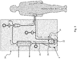
Figure 1 shows in schematic form an extra-corporeal circuit used in a therapeutic treatment, specifically a haemodialysis treatment; -
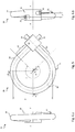
Figure 2 schematically shows a tubular insert and peristaltic pump assembly similar to that indicated by II inFigure 1 ; -
Figure 3 schematically shows another tubular insert and peristaltic pump assembly similar to that ofFigure 2 ; -
Figure 4 shows a cross-sectional view along the line IV-IV inFigure 3 ; -
Figure 5 shows a front view of the tubular insert according toFigure 2 ; -
Figure 6.a shows a first side view of the tubular insert ofFigure 2 ; -
Figure 6.b shows a second side view of the tubular insert ofFigure 2 ; -
Figure 7 shows a front view of the tubular insert according toFigure 3 ; -
Figure 8.a shows a cross-sectional view along the line VIII-VIII inFigure 5 or7 , in the case of a tubular insert according to the prior art; -
Figure 8.b shows a cross-sectional view along the line VIII-VIII inFigure 5 or7 , in the case of the tubular insert according to the invention; -
Figure 9.a shows a cross-sectional view along the line IX-IX inFigure 5 or7 , in the case of a tubular insert according to the prior art; -
Figure 9.b shows a cross-sectional view along the line IX-IX inFigure 5 or7 , in the case of the tubular insert according to the invention; and -
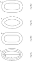
Figures 10 show detailed views of some possible embodiments of the cross-section according toFigure 9.b . - An
insert 28 according to the prior art is described below with reference to the accompanyingFigures 1 ,3 and7 . Thistubular insert 28 is indicated below as the "omega insert", due to its overall Ω-shape. Such insert is widely used for connecting thetube 20 with theperistaltic pump 22 when themachine 24 is prepared for a therapeutic treatment, for example a haemodialysis treatment. - According to this known solution, the disposable circuit, denoted overall by 26, comprises the
tubular insert 28 shown in detail inFigures 3 and7 . From a theoretic point of view, theomega insert 28 can be simply a length of thetube 20 intended to be introduced in theperistaltic pump 22, rather than a separate element. - As can be seen in the accompanying figures, the
tubular insert 28 has aninlet portion 34 and anoutlet portion 36. For greater clarity, with specific reference toFigure 1 , theinlet portion 34 is that intended to be connected to thecircuit section 26 coming from the patient, while theoutlet portion 36 is that intended to be connected to thecircuit section 26 directed towards the dialysing filter. - The
loop 32, as can be seen in the accompanying figures, comprises abroad curve 38 which extends along a circumference having a diameter D. Thebroad curve 38 is connected to thecircuit 26 by means of twotube portions curve 38 of theloop 32 extends, defines an axis intended, during use, to coincide with the axis of rotation of therotor 46 of theperistaltic pump 22. Both these axes are indicated below by a single reference letter X since, during use, they coincide along the same axis. - The
curve 38 is thetube portion 20 intended to be inserted between thestator 44 and therotor 46 of theperistaltic pump 22. In theloop 32 of thetubular insert 28, thecurve 38 extends preferably along an arc β having amplitude greater than 180°, so as to be able to effectively co-operate with therollers 48 ofrotor 46, which are generally two in number and arranged at a distance of 180° from each other. For example, in the embodiment of thetubular insert 28 shown inFigure 7 , thecurve 38 extends along an arc β which has amplitude of 270° or more. - It should be noted that this configuration is a quite theoretical one, and it will be generally assumed by the
loop 32 only when it is inserted insideperistaltic pump 22, while, during the non-operative periods where thetubular insert 28 is separated from theperistaltic pump 22, theloop 32 will assume a generally different form determined solely by the reactions inside thetube 20. - The present invention relates to a novel type of
tubular insert 28 for connecting anextra-corporeal circuit 26 to aperistaltic pump 22. Thetubular insert 28 comprises aloop 32 formed by atube portion 20. Theloop 32 comprises acurve 38 which extends around an axis X. Thetube 20 which forms thecurve 38 has an oval cross-section with a major axis M and a minor axis m perpendicular to each other, the major axis M being longer than the minor axis m. In thetubular insert 28 according to the invention, the minor axis m of each cross-section of thetube 20 along thecurve 38 is parallel to the axis X. - In other words, in the
omega tubular insert 28 according to the invention, the circumference of thecurve 38 lies in the plane of the major axes M of the oval cross-sections. - Hereinbelow, the expression "oval" is understood as meaning a general closed and continuous flat curve which bounds a convex region and which has a major axis M and a minor axis m perpendicular to each other. The oval is a curve preferably without cusps or angled points; this curve has preferably one axis of symmetry, even more preferably has two axes of symmetry.
Figures 10 show some closed and continuous curves which represent specific embodiments of the generic oval shape according to the definition given above. In detail,Figure 10.a . shows an ellipse having major axis M and minor axis m;Figure 10.b shows a curve composed of two circumference arcs having diameter m connected together by two straight segments having length M-m;Figure 10.c shows a curve composed of two circumference arcs having diameter smaller than m connected together by two circumference arcs having diameter greater than M; finally,Figure 10.d shows a generic curve inscribed inside a rectangle having sides M and m. The axes M and m are indicated solely inFigure 10.a in relation to the mean ellipse within the thickness of the wall. Obviously, the person skilled in the art will have no difficulty in applying the indicated parameters also to other possible cases. - The above described
omega insert 28 according to the invention is preferably used in connection with a specificperistaltic pump 22 which is itself part of the invention. Suchperistaltic pump 22 is briefly described hereafter with specific reference tofigures 3 and 4 and. - The peristaltic pump according to the invention is suitable for co-operating with a
common tube 20 having a circular cross section with an external diameter d (see alsofigure 9.a ). Theperistaltic pump 22 comprises, in a manner known per se, astator 44 and arotor 46 defining a rotation axis X and comprising a plurality ofrollers 48 suitable for pressing thetube 20 against thestator 44. In theperistaltic pump 22 according to the invention, therotor 46 further comprises a couple ofradial fingers 54 placed immediately before eachroller 48 with respect to the rotation direction; the minimum axial distance a between theradial fingers 54 is less than d. - In each couple, the two
radial fingers 54 are so arranged to contact thetube 20 on opposite sides. More specifically, in each couple, the tworadial fingers 54 are so arranged to constrain thetube 20 along an axial direction, i.e. a direction perpendicular to the (radial) direction along which theroller 48 presses thetube 20. Such constraint forces the circular section of acommon tube 20 to assume an oval shape according to the invention, i.e. with the minor axis m parallel to the axis X. Similarly, in case of atube 20 or insert 28 with an oval cross section, theradial fingers 54 force them to maintain an oval shape according to the invention, i.e. with the minor axis m parallel to the axis X. - As stated above, the
radial fingers 54 are placed before therollers 48 with respect to the rotation direction. This expression means that, when atube 20 is engaged with theperistaltic pump 22 and therotor 46 is rotating, each section of thetube 20 passes first between the tworadial fingers 54 and, immediately after that, is pressed by theroller 48 against thestator 44. - Each
radial finger 54 preferably comprises a radial roller suitable to rotate around a radial axis Y (seefigure 4 ). Such feature permits to minimize the friction in the contact between theradial finger 54 and the wall of thetube 20 during operation of theperistaltic pump 22. - In each
radial finger 54, the outer radial end (i.e. the end far from axis X) is preferably tapered to a rounded tip (seefigures 4 and5 ). Such feature entails two advantages. First of all the tapering of the outer end allows, at each turn of therotor 46, an easy engagement of theportion 50 of thetube 20 between thefingers 54. As can be clearly seen infigure 4 , the profile of the twofingers 54 defines a large entrance for thetube 20. Such large entrance easily conducts theportion 50 to the narrow space between thefingers 54 even if thetube 20 is in a slightly improper position. Secondly, the rounded tip minimize the risk for theportion 50 to be pricked or even improperly pressed by thefingers 54. - According to an embodiment of the invention (not shown), the
rotor 46 of theperistaltic pump 22 comprises two similar couples ofradial fingers 54 for each roller 48: one placed immediately before and the other placed immediately after theroller 48, with respect to the rotation direction. - Another
insert 28 according to the prior art is described below with reference to the accompanyingFigures 2 ,5 and 6 . Thistubular insert 28 is indicated below as the "alpha insert", due to its overall α-shape. Such particulartubular insert 28 was developed by the Applicant and is widely used for facilitating assembly of thetube 20 with theperistaltic pump 22 when themachine 24 is prepared for a therapeutic treatment, for example a haemodialysis treatment. - According to this known solution, the disposable circuit, denoted overall by 26, comprises the
tubular insert 28, commonly called an "alpha clip", shown in detail inFigures 2 ,5 and 6 . - According to its alpha embodiment, the
tubular insert 28 comprises adouble connector 30 and aloop 32 formed by atube portion 20 of suitable length. As can be seen in the accompanying figures, thetubular insert 28 has overall an alpha shape since theinlet portion 34 and theoutlet portion 36 overlap each other in the region of thedouble connector 30. For greater clarity, with specific reference toFigure 1 , theinlet portion 34 is that intended to be connected to thecircuit section 26 coming from the patient, while theoutlet portion 36 is that intended to be connected to thecircuit section 26 directed towards the dialysing filter. As can be noted from the accompanyingfigures 5 and 6 , theinlet portion 34 and theoutlet portion 36 cross each other, in different planes, inside thedouble connector 30. - The
loop 32, as can be seen in the accompanyingfigures 2 ,5 and 6 , comprises abroad curve 38 which extends along a cylindrical helix and is connected to theconnector 30 by means of two substantiallystraight tube segments curve 38 of theloop 32 extends, defines an axis intended, during use, to coincide with the axis of rotation of therotor 46 of theperistaltic pump 22. Both these axes are indicated below by a single reference letter X since, during use, they coincide along the same axis. Moreover, the cylindrical helix has a pitch p which is decidedly smaller than the diameter D such that, according to a first approximation, it may be considered that thecurve 38 lies in a plane and therefore describes the arc of a circumference. It should be considered, for example, that, according to a first preferred embodiment, the diameter D of the cylindrical helix is about 50 mm, while the pitch p is only about 6 mm. In view of this approximation, most of the remarks reported above with respect to the omega insert are also valid with respect to the alpha insert. - The approximation of the cylindrical helix portion to an arc of a circumference having the same diameter D is further justified in that the
peristaltic pump 22 acts on thetubular insert 28 exactly as though the latter were extending in a plane perpendicular to the axis X of therotor 46. This slight geometric discrepancy is fully offset in reality by the deformability of thetube 20. - The
curve 38 is thetube portion 20 intended to be inserted between thestator 44 and therotor 46 of theperistaltic pump 22. In theloop 32 of thetubular insert 28, thecurve 38 extends preferably along an arc β having an amplitude greater than 180°, so as to be able to effectively co-operate with therotor 46, therollers 48 of which are generally two in number and arranged at a distance of 180° from each other. For example, in the embodiment of thetubular insert 28 shown inFigure 5 , thecurve 38 extends along an arc β which has an amplitude of about 270°. It should be noted that this configuration is a quite theoretical one, and it will be generally assumed by theloop 32 only when it is inserted insideperistaltic pump 22, while, during the non-operative periods where thetubular insert 28 is separated from theperistaltic pump 22, theloop 32 will assume a generally different form determined solely by the reactions inside thetube 20. - The present invention also relates to a novel type of the
alpha tubular insert 28. Suchtubular insert 28 for connecting anextra-corporeal circuit 26 to aperistaltic pump 22, comprises adouble connector 30 and aloop 32 formed by atube portion 20. Theloop 32 comprises acurve 38 which extends around an axis X and is connected to thedouble connector 30 by means of two substantiallystraight tube segments tube 20 which forms thecurve 38 has an oval cross-section with a major axis M and a minor axis m perpendicular to each other, the major axis M being longer than the minor axis m. The minor axis m of each cross-section of thetube 20 along thecurve 38 is parallel to the axis X. - If the curve described by the
loop 32 is approximated to a circumference instead of to a cylindrical helix, in thetubular insert 28 according to the invention, that circumference lies in the plane of the major axes M of the oval cross-sections. - As already explained above, the expression "oval" is understood as meaning a general closed and continuous flat curve which bounds a convex region and which has a major axis M and a minor axis m perpendicular to each other.
- Specific studies conducted by the Applicant have shown that the oval shape of the cross-section of the
tube 20 according to the invention is able to solve most of the problems reported above with respect to the prior art. - As a person skilled in the art is well aware, the mechanical characteristics of the
tube 20 depend, among other things, on the intrinsic characteristics of the material and on the geometric characteristics of the involved sections. In the specific case of thetube 20 according to the invention, the geometric characteristics are considerably more advantageous than those of the prior art tubes. - The
tube 20 of thetubular insert 28 according to the prior art is generally made of PVC plasticized with a suitable additive, usually DOP. Thetube 20 of thetubular insert 28 according to the invention may be made of any material suitable for the specific use. In particular, it is preferably made of PVC plasticized with a suitable additive. The plasticizer can be advantageously TOTM, in order to comply with the new standards which aim to abolish DOP. - With respect to the overall mechanical characteristics of the
tube 20, it is to be noted here that the intrinsic characteristics of the PVC material are significantly penalized by the replacement of DOP with TOTM. However, the studies conducted by the Applicant have shown that the geometric characteristics of the oval cross-sections of thetube 20 according to the invention are able to overcome in an optimum manner this negative consequence. - A number of results of tests carried out by the Applicant, in order to compare the characteristics of the
tube 20 with an oval cross-section according to the invention with those of theconventional tube 20 which has a circular cross-section, where both tubes are made of PVC-TOTM, are described below. Atube 20, the oval section of which has a length equal to the length of the circumference defining the section of the tube of the known type, was considered. A new tube according to the invention ensures a flow rate of about 320 ml/min and is subject, after 6 hours continuous operation, to a slight reduction in flow rate of between 4% and 5%. - From the above it can be understood immediately how the tubular insert according to the invention ensures a better performance than similar inserts of the known type, both in the case of PVC-TOTM inserts and - this being a particularly significant result - in the case of PVC-DOP inserts.
- As already reported above, both the omega and the alpha configurations previously described for the
loop 32 according to the prior art, are theoretical ones. In practice thetube 20, especially when it is not engaged with theperistaltic pump 22, assumes a different overall configuration which minimizes the deformation energy. - According to its real configuration, the length of the
tube 20 intended to originate anomega insert 28 is almost straight. The described omega configuration will be assumed by theloop 32 when it is inserted insideperistaltic pump 22; the act of bending the straight length oftube 20 entails a deformation of the involved cross sections which is disclosed below. - According to its real configuration, the
loop 32 of analpha insert 28 comprises acurve 38 which extends along an arc β having an amplitude smaller than the theoretical one and which has a diameter smaller than the theoretical one. Moreover, thereal loop 32 comprises twotube segments figures 8.a , thetube 20 has, at the apex ofcurve 38, an oval cross-section with its major axis M parallel to the axis X, i.e. opposite to the one described above with respect to the invention. In other words, thetubular insert 28 according to the prior art, spontaneously assume an inefficient configuration, in which the geometric characteristics of the cross-sections noticeably penalize the overall mechanical characteristics of thetube 20. - As the skilled person may easily understand, the
radial fingers 54 of therotor 46 described above are intended to force thetube 20 in the right configuration according to the invention (i.e. with the minor axes m of the cross-sections of thetube 20 parallel to axis X), even if thetube 20 tends to spontaneously assume the opposite configuration which minimizes the deformation energy (i.e. with the minor axes m of the cross-sections of thetube 20 perpendicular to axis X). This function of theradial fingers 54 is very important in the case of anomega insert 28 obtained with a length of thetube 20, i.e. aninsert 28 in which thetube 20, contrary to the alpha insert, has no constraint with respect to its orientation. - As already described above, the production of the omega tubular inserts 28 according to the prior art simply involves providing a
tube portion 20 of suitable length and curving it so as to form theloop 32. - The production of the alpha tubular inserts 28 according to the prior art involves providing a
double connector 30 and atube portion 20 of suitable length which is curved so as to form theloop 32. Each end of thetube 20 is then fitted onto a proper attachment provided on thedouble connector 30. - In order to produce a
tubular insert 28 according to the invention (either an omega or alpha one) it was proposed using the conventional method described above, subject to the sole condition of using atube 20 with an oval cross-section instead of theconventional tube 20 with a circular cross-section. Obviously, in order to obtain aninsert 28 according to the invention, thetube 20 with an oval cross-section must be curved so that the axis X of theloop 32 is parallel to the minor axes m of the cross-sections For both the omega insert and, adopting the usual approximation mentioned above, for the alpha insert, it may also be said that thetube 20 must be curved so that theloop 32 remains within the plane which contains the major axes M of the cross-sections of thetube 20 itself. - This method, however, does not produce satisfactory results. It was noted, in fact, that, owing to the geometric characteristics of the oval cross-section, the curvature of the
tube 20 in the plane of the major axes M does not provide a stable equilibrium for the insert system as a whole. The result is that thetube 20 spontaneously tends to transfer the curvature into a plane containing the minor axes m, where the moment of inertia of the oval cross-section is lower. This occurs at least at a distance from the external constraints acting on thetube 20, if any, like the attachments of thedouble connector 30 in the alpha form. The result is that, in the alpha form with torsional constraints in the region of the attachment points on thedouble connector 30, theloop 32 no longer lies either along a cylindrical helix or in a plane, but describes a three-dimensional curve which lies well outside the desired plane. Conversely, in the omega form and in the alpha form without torsional constraints acting at the attachments points on thedouble connector 30, also the ends of thetube 20 tend to rotate. Theentire tube 20 thus assumes a position where the curvature of theloop 32 lies in the plane of the minor axes m, thus producing a result opposite to that described above for thetubular insert 28 according to the invention. - The method for producing an
insert 28 according to the invention comprises the steps of: - Providing a
tube portion 20 which has a circular cross-section and a suitable length; - Bending the
tube portion 20 so as to form theloop 32; - Subjecting the
loop 32 to compression along the axis X so as to ovalize the cross-sections of thetube 20 at least in the zone of thecurve 38; and - At the same time as compression along the axis X, subjecting the
loop 32 to a physical treatment suitable to allow internal reorganization of the material which stabilizes its deformed condition. - Accordingly, the
loop 32 is formed from atube portion 20 of the conventional type, typically with a circular cross-section. Only subsequently theloop 32 is subjected to a combined compressive action along the axis X and a physical treatment, e.g. a thermal cycle for heating and cooling the material. In this way it is ensured that the curvature of theloop 32 and the deformation of the cross-sections of thetube 20 caused by compression are rendered permanent by the physical treatment. The physical treatment, e.g. the heating step in the deformed state and the subsequent cooling step, in fact result in internal reorganization of the material which stabilizes its condition. In this way it is ensured that the axis X of theloop 32 is stably parallel to the minor axes m of the cross-sections or, adopting the usual approximation, that theloop 32 is stably contained within the plane which contains the major axes M of the cross-sections of thetube 20 itself. - According to some embodiments, the method further comprises the steps of providing a
double connector 30 and connecting theloop 32 to thedouble connector 30. - According to some other embodiments of the method according to the invention, ultrasonic treatments and/or radiofrequency treatments are used, instead of the thermal cycle, in order to speed up the production of the
tubular insert 28. In order to satisfy specific needs, a combination of thermal, ultrasonic and/or radiofrequency treatments can be used. - As the person skilled in the art may well understood from that described above, the
tubular insert 28, theperistaltic pump 22 and the method for producing theinsert 28 according to the invention are able to solve at least partly the drawbacks mentioned above in relation to the prior art. - In particular, it will be clear how the
tubular insert 28 according to the invention has a high degree of elasticity so as to achieve an optimum performance in terms of flow rate and a limited deterioration thereof following long periods of operation, even in the case where the tube is made of PVC-TOTM. - Moreover, the peristaltic pump according to the invention is able to obtain, from the well-known tubular inserts, advantages similar to those obtainable with the tubular inserts 28 according to the invention. The pump according to the invention is suitable for co-operating, without distinction, with the
insert 28 according to the invention (both in its alpha and omega form) or with a tubular insert commonly used in the peristaltic pumps according to the prior art. - Lastly, it will also be clear to the person skilled in the art how both the tubular inserts 28, the
peristaltic pump 22 and the method for producing theinsert 28 constitute a simple and low-cost solution. - With regard to the embodiments of the tubular insert, of the peristaltic pump and of the production method described above, the person skilled in the art may, in order to satisfy specific requirements, make modifications to and/or replace elements described with equivalent elements, without thereby departing from the scope of the accompanying claims.
Claims (8)
- Peristaltic pump (22) suitable for co-operating with a tube (20) having a circular cross section with an external diameter d, the peristaltic pump (22) comprising a stator (44) and a rotor (46) defining a rotation axis X and comprising a plurality of rollers (48) suitable for pressing the tube (20) against the stator (44), wherein the rotor (46) further comprises a couple of radial fingers (54) placed immediately before each roller (48) with respect to the rotation direction, the minimum axial distance (a) between the radial fingers (54) being less than d.
- Peristaltic pump (22) according to claim 1, wherein each radial finger (54) comprises a radial roller suitable to rotate around a radial axis Y so as to minimize the friction in the contact between the radial finger (54) and the wall of the tube (20) during operation of the peristaltic pump (22).
- Peristaltic pump (22) according to claim 1 or 2, wherein the outer radial end of each radial finger (54) is tapered to a rounded tip.
- Peristaltic pump (22) according to any one of claims 1 to 3, wherein the rotor (46) comprises two couples of radial fingers (54) for each roller (48), one placed immediately before and the other placed immediately after the roller (48), with respect to the rotation direction.
- Extra-corporeal circuit (26) for circulation of a physiological liquid, comprising a peristaltic pump (22) in accordance with any one of claims 1-4 and a tubular insert (28) comprising a loop (32) formed by a tube portion (20), wherein the loop (32) comprises a curve (38) which extends around an axis X, where the tube (20) which forms the curve (38) has an oval cross-section with a major axis M and a minor axis m perpendicular to each other, the major axis M being longer than the minor axis m, and wherein the minor axis m of each cross-section of the tube (20) along the curve (38) is parallel to the axis X..
- Extra-corporeal circuit (26) according to claim 5, wherein the radial fingers (54) of the peristaltic pump (22) forces the insert (28) to maintain its orientation in which the minor axis m of each cross-section of the tube (20) along the curve (38) is parallel to the axis X.
- Extra-corporeal circuit (26) for circulation of a physiological liquid, comprising a tube (20) having a circular cross-section and a peristaltic pump (22) according to any one of claims 7 to 9, wherein the radial fingers (54) forces the tube (20) to assume an oval cross-section with a major axis M and a minor axis m perpendicular to each other, the major axis M being longer than the minor axis m, and wherein the minor axis m of each cross-section of the tube (20) along the curve (38) is parallel to the axis X.
- Machine (24) suitable for carrying out therapeutic treatments, comprising an extra-corporeal circuit according to any claim 5 to 7.
Applications Claiming Priority (3)
| Application Number | Priority Date | Filing Date | Title |
|---|---|---|---|
| EP11425110A EP2514451A1 (en) | 2011-04-21 | 2011-04-21 | Tubular insert for extra-corporeal circuit |
| PCT/EP2012/057144 WO2012143432A1 (en) | 2011-04-21 | 2012-04-19 | Tubular insert for extra-corporeal circuit |
| EP12715389.8A EP2699285B1 (en) | 2011-04-21 | 2012-04-19 | Tubular insert for extra-corporeal circuit |
Related Parent Applications (2)
| Application Number | Title | Priority Date | Filing Date |
|---|---|---|---|
| EP12715389.8A Division-Into EP2699285B1 (en) | 2011-04-21 | 2012-04-19 | Tubular insert for extra-corporeal circuit |
| EP12715389.8A Division EP2699285B1 (en) | 2011-04-21 | 2012-04-19 | Tubular insert for extra-corporeal circuit |
Publications (2)
| Publication Number | Publication Date |
|---|---|
| EP3492122A1 true EP3492122A1 (en) | 2019-06-05 |
| EP3492122B1 EP3492122B1 (en) | 2020-07-01 |
Family
ID=44584799
Family Applications (3)
| Application Number | Title | Priority Date | Filing Date |
|---|---|---|---|
| EP11425110A Withdrawn EP2514451A1 (en) | 2011-04-21 | 2011-04-21 | Tubular insert for extra-corporeal circuit |
| EP19152867.8A Active EP3492122B1 (en) | 2011-04-21 | 2012-04-19 | Extra-corporeal circuit |
| EP12715389.8A Active EP2699285B1 (en) | 2011-04-21 | 2012-04-19 | Tubular insert for extra-corporeal circuit |
Family Applications Before (1)
| Application Number | Title | Priority Date | Filing Date |
|---|---|---|---|
| EP11425110A Withdrawn EP2514451A1 (en) | 2011-04-21 | 2011-04-21 | Tubular insert for extra-corporeal circuit |
Family Applications After (1)
| Application Number | Title | Priority Date | Filing Date |
|---|---|---|---|
| EP12715389.8A Active EP2699285B1 (en) | 2011-04-21 | 2012-04-19 | Tubular insert for extra-corporeal circuit |
Country Status (5)
| Country | Link |
|---|---|
| US (1) | US20140037480A1 (en) |
| EP (3) | EP2514451A1 (en) |
| JP (2) | JP2014518525A (en) |
| CN (1) | CN103764198B (en) |
| WO (1) | WO2012143432A1 (en) |
Families Citing this family (10)
| Publication number | Priority date | Publication date | Assignee | Title |
|---|---|---|---|---|
| EP2781234A1 (en) | 2013-03-20 | 2014-09-24 | Fresenius Medical Care Deutschland GmbH | Tube for extra-corporeal circuit with double connector |
| KR20160012981A (en) * | 2013-05-23 | 2016-02-03 | 한닝 일렉트로-베르케 게엠베하 운트 코. 카게 | Pump arrangement |
| US10352315B2 (en) * | 2014-11-26 | 2019-07-16 | Fenwal, Inc. | Auto loading and unloading peristaltic pump apparatus |
| DE102015105323A1 (en) * | 2015-04-08 | 2016-10-13 | B. Braun Avitum Ag | Fluid delivery monitoring method in an extracorporeal blood treatment device |
| CN105120217B (en) * | 2015-08-21 | 2018-06-22 | 上海小蚁科技有限公司 | Intelligent camera mobile detection alert system and method based on big data analysis and user feedback |
| DE102016005467A1 (en) * | 2016-05-06 | 2017-11-09 | Fresenius Medical Care Deutschland Gmbh | Medical treatment device and tubing set for a medical treatment device and method for monitoring a peristaltic peristaltic pump |
| US10008503B1 (en) * | 2016-12-27 | 2018-06-26 | Micron Technology, Inc. | Memory devices which include memory arrays |
| IT201700064361A1 (en) * | 2017-06-09 | 2018-12-09 | Allmed Medical Care Holdings Ltd | SUPPORT FOR A CURVE PORTION OF A DUCT |
| JP7220580B2 (en) * | 2019-02-08 | 2023-02-10 | 東京エレクトロン株式会社 | Tubing body and pump device |
| DE102019133969A1 (en) * | 2019-12-11 | 2021-06-17 | Fresenius Medical Care Deutschland Gmbh | Delivery device for delivering medical fluids through a hose |
Citations (7)
| Publication number | Priority date | Publication date | Assignee | Title |
|---|---|---|---|---|
| US3737256A (en) * | 1971-07-16 | 1973-06-05 | Sarns Inc | Peristaltic pump construction |
| GB1378361A (en) * | 1972-03-07 | 1974-12-27 | Rugel H | Viscous material applicator |
| GB1380812A (en) * | 1972-09-28 | 1975-01-15 | Chafer Ltd J W | Tubing and pumps incorporating such tubing |
| US4558996A (en) * | 1983-06-30 | 1985-12-17 | Organon Teknika Corporation | Easy load peristaltic pump |
| US5468129A (en) * | 1994-08-05 | 1995-11-21 | Cole Parmer Instrument Company | Peristaltic pump |
| WO2000070225A1 (en) * | 1999-05-12 | 2000-11-23 | G John Andersen | Peristaltic fluid pump |
| US20100329910A1 (en) * | 2004-05-14 | 2010-12-30 | Fresenius Medical Care Deutschlang Gmbh | Roller pump |
Family Cites Families (22)
| Publication number | Priority date | Publication date | Assignee | Title |
|---|---|---|---|---|
| US3918854A (en) * | 1974-06-19 | 1975-11-11 | Alphamedics Mfg Corp | Peristaltic pump |
| JPH076508B2 (en) * | 1990-10-19 | 1995-01-30 | 東海ゴム工業株式会社 | Pumping tube |
| US5281112A (en) * | 1992-02-25 | 1994-01-25 | The Regents Of The University Of Michigan | Self regulating blood pump with controlled suction |
| US5342181A (en) * | 1992-06-15 | 1994-08-30 | Datascope Investment Corp. | Single roller blood pump and pump/oxygenator system using same |
| JPH0617770A (en) * | 1992-07-06 | 1994-01-25 | Fujita Corp | Tube pump |
| JPH08126699A (en) * | 1994-10-31 | 1996-05-21 | Terumo Corp | Multi-layer tube |
| US5846061A (en) * | 1996-11-08 | 1998-12-08 | Board Of Trustees Of Michigan State University | Peristaltic metering pump |
| US6168397B1 (en) * | 1997-07-01 | 2001-01-02 | Daiichi Techno Co., Ltd. | Flexible tube of squeeze pump |
| JP4213272B2 (en) * | 1998-11-16 | 2009-01-21 | Ihi建機株式会社 | Squeeze type concrete pump |
| WO2000048659A2 (en) * | 1999-02-19 | 2000-08-24 | Endoscopic Technologies, Inc. | Multichannel catheter with obturator |
| JP3798925B2 (en) * | 1999-08-11 | 2006-07-19 | テルモ株式会社 | Blood component collection device |
| CN2392929Y (en) * | 1999-10-15 | 2000-08-23 | 梁成英 | Multifunction sebific-duct pump |
| IT1318444B1 (en) * | 2000-04-03 | 2003-08-25 | Dideco Spa | INTRAOPERATIVE SELF-TRANSFUSION DEVICE. |
| US6406267B1 (en) * | 2000-06-16 | 2002-06-18 | Claude F. Mondiere | Extracorporeal circulation pump |
| US8323228B2 (en) * | 2007-04-12 | 2012-12-04 | Rex Medical L.P. | Dialysis catheter |
| US7077829B2 (en) * | 2001-01-09 | 2006-07-18 | Rex Medical, L.P. | Dialysis catheter |
| US6858019B2 (en) * | 2001-01-09 | 2005-02-22 | Rex Medical, L.P. | Dialysis catheter and methods of insertion |
| JP2003206870A (en) * | 2002-01-10 | 2003-07-25 | Seiko Epson Corp | Tube pump and ink jet recording device using the tube pump |
| JP2004097599A (en) * | 2002-09-11 | 2004-04-02 | Kawasumi Lab Inc | Blood circuit for high pressure steam sterilization treatment |
| ITMO20040223A1 (en) * | 2004-09-06 | 2004-12-06 | Gambro Lundia Ab | PIPE FOR A PERISTALTIC PUMP. |
| KR20090005320A (en) * | 2006-04-06 | 2009-01-13 | 프레제니우스 메디칼 케어 도이칠란드 게엠베하 | Tube for medical purposes |
| US7963690B2 (en) * | 2006-11-28 | 2011-06-21 | Tylerville Technologies Llc | Dispenser with dynamic mixer for two-part compositions |
-
2011
- 2011-04-21 EP EP11425110A patent/EP2514451A1/en not_active Withdrawn
-
2012
- 2012-04-19 WO PCT/EP2012/057144 patent/WO2012143432A1/en active Application Filing
- 2012-04-19 JP JP2014505617A patent/JP2014518525A/en active Pending
- 2012-04-19 US US14/112,617 patent/US20140037480A1/en not_active Abandoned
- 2012-04-19 EP EP19152867.8A patent/EP3492122B1/en active Active
- 2012-04-19 EP EP12715389.8A patent/EP2699285B1/en active Active
- 2012-04-19 CN CN201280030446.8A patent/CN103764198B/en active Active
-
2017
- 2017-12-07 JP JP2017235197A patent/JP2018064965A/en active Pending
Patent Citations (7)
| Publication number | Priority date | Publication date | Assignee | Title |
|---|---|---|---|---|
| US3737256A (en) * | 1971-07-16 | 1973-06-05 | Sarns Inc | Peristaltic pump construction |
| GB1378361A (en) * | 1972-03-07 | 1974-12-27 | Rugel H | Viscous material applicator |
| GB1380812A (en) * | 1972-09-28 | 1975-01-15 | Chafer Ltd J W | Tubing and pumps incorporating such tubing |
| US4558996A (en) * | 1983-06-30 | 1985-12-17 | Organon Teknika Corporation | Easy load peristaltic pump |
| US5468129A (en) * | 1994-08-05 | 1995-11-21 | Cole Parmer Instrument Company | Peristaltic pump |
| WO2000070225A1 (en) * | 1999-05-12 | 2000-11-23 | G John Andersen | Peristaltic fluid pump |
| US20100329910A1 (en) * | 2004-05-14 | 2010-12-30 | Fresenius Medical Care Deutschlang Gmbh | Roller pump |
Also Published As
| Publication number | Publication date |
|---|---|
| CN103764198A (en) | 2014-04-30 |
| EP2514451A1 (en) | 2012-10-24 |
| WO2012143432A1 (en) | 2012-10-26 |
| CN103764198B (en) | 2017-06-20 |
| US20140037480A1 (en) | 2014-02-06 |
| EP2699285A1 (en) | 2014-02-26 |
| JP2014518525A (en) | 2014-07-31 |
| EP2699285B1 (en) | 2019-06-26 |
| EP3492122B1 (en) | 2020-07-01 |
| JP2018064965A (en) | 2018-04-26 |
Similar Documents
| Publication | Publication Date | Title |
|---|---|---|
| EP3492122B1 (en) | Extra-corporeal circuit | |
| US11060516B2 (en) | Peristaltic pump tube | |
| AU2014234425B2 (en) | Tube for extra-corporeal circuit with double connector | |
| US20090053084A1 (en) | Roller pump and peristaltic tubing with atrium | |
| CN108496005B (en) | Micro-dose peristaltic pump for micro-dosed fluids | |
| US11679232B2 (en) | Flushing system | |
| US10918828B2 (en) | Kink and compression tolerant medical tubing | |
| EP4438102A1 (en) | Connector for connecting a pump hose segment to a pump bed of a peristaltic pump | |
| CN218943996U (en) | Pump for medical dialysis instrument | |
| AU2023202317A1 (en) | Infusion system and catheter for such an infusion system |
Legal Events
| Date | Code | Title | Description |
|---|---|---|---|
| PUAI | Public reference made under article 153(3) epc to a published international application that has entered the european phase |
Free format text: ORIGINAL CODE: 0009012 |
|
| STAA | Information on the status of an ep patent application or granted ep patent |
Free format text: STATUS: THE APPLICATION HAS BEEN PUBLISHED |
|
| AC | Divisional application: reference to earlier application |
Ref document number: 2699285 Country of ref document: EP Kind code of ref document: P |
|
| AK | Designated contracting states |
Kind code of ref document: A1 Designated state(s): AL AT BE BG CH CY CZ DE DK EE ES FI FR GB GR HR HU IE IS IT LI LT LU LV MC MK MT NL NO PL PT RO RS SE SI SK SM TR |
|
| STAA | Information on the status of an ep patent application or granted ep patent |
Free format text: STATUS: REQUEST FOR EXAMINATION WAS MADE |
|
| 17P | Request for examination filed |
Effective date: 20191112 |
|
| RBV | Designated contracting states (corrected) |
Designated state(s): AL AT BE BG CH CY CZ DE DK EE ES FI FR GB GR HR HU IE IS IT LI LT LU LV MC MK MT NL NO PL PT RO RS SE SI SK SM TR |
|
| RIC1 | Information provided on ipc code assigned before grant |
Ipc: A61M 1/10 20060101ALI20191219BHEP Ipc: F16L 11/12 20060101ALI20191219BHEP Ipc: F04B 43/12 20060101ALI20191219BHEP Ipc: A61M 5/142 20060101AFI20191219BHEP Ipc: F04B 43/00 20060101ALI20191219BHEP |
|
| GRAP | Despatch of communication of intention to grant a patent |
Free format text: ORIGINAL CODE: EPIDOSNIGR1 |
|
| STAA | Information on the status of an ep patent application or granted ep patent |
Free format text: STATUS: GRANT OF PATENT IS INTENDED |
|
| INTG | Intention to grant announced |
Effective date: 20200131 |
|
| GRAS | Grant fee paid |
Free format text: ORIGINAL CODE: EPIDOSNIGR3 |
|
| GRAA | (expected) grant |
Free format text: ORIGINAL CODE: 0009210 |
|
| STAA | Information on the status of an ep patent application or granted ep patent |
Free format text: STATUS: THE PATENT HAS BEEN GRANTED |
|
| AC | Divisional application: reference to earlier application |
Ref document number: 2699285 Country of ref document: EP Kind code of ref document: P |
|
| AK | Designated contracting states |
Kind code of ref document: B1 Designated state(s): AL AT BE BG CH CY CZ DE DK EE ES FI FR GB GR HR HU IE IS IT LI LT LU LV MC MK MT NL NO PL PT RO RS SE SI SK SM TR |
|
| REG | Reference to a national code |
Ref country code: CH Ref legal event code: EP Ref country code: AT Ref legal event code: REF Ref document number: 1285547 Country of ref document: AT Kind code of ref document: T Effective date: 20200715 |
|
| REG | Reference to a national code |
Ref country code: IE Ref legal event code: FG4D |
|
| REG | Reference to a national code |
Ref country code: DE Ref legal event code: R096 Ref document number: 602012071084 Country of ref document: DE |
|
| REG | Reference to a national code |
Ref country code: LT Ref legal event code: MG4D |
|
| PG25 | Lapsed in a contracting state [announced via postgrant information from national office to epo] |
Ref country code: BG Free format text: LAPSE BECAUSE OF FAILURE TO SUBMIT A TRANSLATION OF THE DESCRIPTION OR TO PAY THE FEE WITHIN THE PRESCRIBED TIME-LIMIT Effective date: 20201001 |
|
| REG | Reference to a national code |
Ref country code: NL Ref legal event code: MP Effective date: 20200701 |
|
| REG | Reference to a national code |
Ref country code: AT Ref legal event code: MK05 Ref document number: 1285547 Country of ref document: AT Kind code of ref document: T Effective date: 20200701 |
|
| PG25 | Lapsed in a contracting state [announced via postgrant information from national office to epo] |
Ref country code: CZ Free format text: LAPSE BECAUSE OF FAILURE TO SUBMIT A TRANSLATION OF THE DESCRIPTION OR TO PAY THE FEE WITHIN THE PRESCRIBED TIME-LIMIT Effective date: 20200701 Ref country code: SE Free format text: LAPSE BECAUSE OF FAILURE TO SUBMIT A TRANSLATION OF THE DESCRIPTION OR TO PAY THE FEE WITHIN THE PRESCRIBED TIME-LIMIT Effective date: 20200701 Ref country code: ES Free format text: LAPSE BECAUSE OF FAILURE TO SUBMIT A TRANSLATION OF THE DESCRIPTION OR TO PAY THE FEE WITHIN THE PRESCRIBED TIME-LIMIT Effective date: 20200701 Ref country code: HR Free format text: LAPSE BECAUSE OF FAILURE TO SUBMIT A TRANSLATION OF THE DESCRIPTION OR TO PAY THE FEE WITHIN THE PRESCRIBED TIME-LIMIT Effective date: 20200701 Ref country code: LT Free format text: LAPSE BECAUSE OF FAILURE TO SUBMIT A TRANSLATION OF THE DESCRIPTION OR TO PAY THE FEE WITHIN THE PRESCRIBED TIME-LIMIT Effective date: 20200701 Ref country code: FI Free format text: LAPSE BECAUSE OF FAILURE TO SUBMIT A TRANSLATION OF THE DESCRIPTION OR TO PAY THE FEE WITHIN THE PRESCRIBED TIME-LIMIT Effective date: 20200701 Ref country code: PT Free format text: LAPSE BECAUSE OF FAILURE TO SUBMIT A TRANSLATION OF THE DESCRIPTION OR TO PAY THE FEE WITHIN THE PRESCRIBED TIME-LIMIT Effective date: 20201102 Ref country code: AT Free format text: LAPSE BECAUSE OF FAILURE TO SUBMIT A TRANSLATION OF THE DESCRIPTION OR TO PAY THE FEE WITHIN THE PRESCRIBED TIME-LIMIT Effective date: 20200701 Ref country code: GR Free format text: LAPSE BECAUSE OF FAILURE TO SUBMIT A TRANSLATION OF THE DESCRIPTION OR TO PAY THE FEE WITHIN THE PRESCRIBED TIME-LIMIT Effective date: 20201002 Ref country code: NO Free format text: LAPSE BECAUSE OF FAILURE TO SUBMIT A TRANSLATION OF THE DESCRIPTION OR TO PAY THE FEE WITHIN THE PRESCRIBED TIME-LIMIT Effective date: 20201001 |
|
| PG25 | Lapsed in a contracting state [announced via postgrant information from national office to epo] |
Ref country code: PL Free format text: LAPSE BECAUSE OF FAILURE TO SUBMIT A TRANSLATION OF THE DESCRIPTION OR TO PAY THE FEE WITHIN THE PRESCRIBED TIME-LIMIT Effective date: 20200701 Ref country code: RS Free format text: LAPSE BECAUSE OF FAILURE TO SUBMIT A TRANSLATION OF THE DESCRIPTION OR TO PAY THE FEE WITHIN THE PRESCRIBED TIME-LIMIT Effective date: 20200701 Ref country code: LV Free format text: LAPSE BECAUSE OF FAILURE TO SUBMIT A TRANSLATION OF THE DESCRIPTION OR TO PAY THE FEE WITHIN THE PRESCRIBED TIME-LIMIT Effective date: 20200701 Ref country code: IS Free format text: LAPSE BECAUSE OF FAILURE TO SUBMIT A TRANSLATION OF THE DESCRIPTION OR TO PAY THE FEE WITHIN THE PRESCRIBED TIME-LIMIT Effective date: 20201101 |
|
| PG25 | Lapsed in a contracting state [announced via postgrant information from national office to epo] |
Ref country code: NL Free format text: LAPSE BECAUSE OF FAILURE TO SUBMIT A TRANSLATION OF THE DESCRIPTION OR TO PAY THE FEE WITHIN THE PRESCRIBED TIME-LIMIT Effective date: 20200701 |
|
| REG | Reference to a national code |
Ref country code: DE Ref legal event code: R097 Ref document number: 602012071084 Country of ref document: DE |
|
| PG25 | Lapsed in a contracting state [announced via postgrant information from national office to epo] |
Ref country code: SM Free format text: LAPSE BECAUSE OF FAILURE TO SUBMIT A TRANSLATION OF THE DESCRIPTION OR TO PAY THE FEE WITHIN THE PRESCRIBED TIME-LIMIT Effective date: 20200701 Ref country code: EE Free format text: LAPSE BECAUSE OF FAILURE TO SUBMIT A TRANSLATION OF THE DESCRIPTION OR TO PAY THE FEE WITHIN THE PRESCRIBED TIME-LIMIT Effective date: 20200701 Ref country code: RO Free format text: LAPSE BECAUSE OF FAILURE TO SUBMIT A TRANSLATION OF THE DESCRIPTION OR TO PAY THE FEE WITHIN THE PRESCRIBED TIME-LIMIT Effective date: 20200701 Ref country code: DK Free format text: LAPSE BECAUSE OF FAILURE TO SUBMIT A TRANSLATION OF THE DESCRIPTION OR TO PAY THE FEE WITHIN THE PRESCRIBED TIME-LIMIT Effective date: 20200701 |
|
| PLBE | No opposition filed within time limit |
Free format text: ORIGINAL CODE: 0009261 |
|
| STAA | Information on the status of an ep patent application or granted ep patent |
Free format text: STATUS: NO OPPOSITION FILED WITHIN TIME LIMIT |
|
| PG25 | Lapsed in a contracting state [announced via postgrant information from national office to epo] |
Ref country code: AL Free format text: LAPSE BECAUSE OF FAILURE TO SUBMIT A TRANSLATION OF THE DESCRIPTION OR TO PAY THE FEE WITHIN THE PRESCRIBED TIME-LIMIT Effective date: 20200701 |
|
| 26N | No opposition filed |
Effective date: 20210406 |
|
| PG25 | Lapsed in a contracting state [announced via postgrant information from national office to epo] |
Ref country code: SK Free format text: LAPSE BECAUSE OF FAILURE TO SUBMIT A TRANSLATION OF THE DESCRIPTION OR TO PAY THE FEE WITHIN THE PRESCRIBED TIME-LIMIT Effective date: 20200701 |
|
| PG25 | Lapsed in a contracting state [announced via postgrant information from national office to epo] |
Ref country code: SI Free format text: LAPSE BECAUSE OF FAILURE TO SUBMIT A TRANSLATION OF THE DESCRIPTION OR TO PAY THE FEE WITHIN THE PRESCRIBED TIME-LIMIT Effective date: 20200701 |
|
| PG25 | Lapsed in a contracting state [announced via postgrant information from national office to epo] |
Ref country code: MC Free format text: LAPSE BECAUSE OF FAILURE TO SUBMIT A TRANSLATION OF THE DESCRIPTION OR TO PAY THE FEE WITHIN THE PRESCRIBED TIME-LIMIT Effective date: 20200701 |
|
| GBPC | Gb: european patent ceased through non-payment of renewal fee |
Effective date: 20210419 |
|
| PG25 | Lapsed in a contracting state [announced via postgrant information from national office to epo] |
Ref country code: LU Free format text: LAPSE BECAUSE OF NON-PAYMENT OF DUE FEES Effective date: 20210419 |
|
| REG | Reference to a national code |
Ref country code: BE Ref legal event code: MM Effective date: 20210430 |
|
| PG25 | Lapsed in a contracting state [announced via postgrant information from national office to epo] |
Ref country code: GB Free format text: LAPSE BECAUSE OF NON-PAYMENT OF DUE FEES Effective date: 20210419 Ref country code: CH Free format text: LAPSE BECAUSE OF NON-PAYMENT OF DUE FEES Effective date: 20210430 Ref country code: LI Free format text: LAPSE BECAUSE OF NON-PAYMENT OF DUE FEES Effective date: 20210430 |
|
| PG25 | Lapsed in a contracting state [announced via postgrant information from national office to epo] |
Ref country code: IE Free format text: LAPSE BECAUSE OF NON-PAYMENT OF DUE FEES Effective date: 20210419 |
|
| PG25 | Lapsed in a contracting state [announced via postgrant information from national office to epo] |
Ref country code: IS Free format text: LAPSE BECAUSE OF FAILURE TO SUBMIT A TRANSLATION OF THE DESCRIPTION OR TO PAY THE FEE WITHIN THE PRESCRIBED TIME-LIMIT Effective date: 20201101 |
|
| PG25 | Lapsed in a contracting state [announced via postgrant information from national office to epo] |
Ref country code: BE Free format text: LAPSE BECAUSE OF NON-PAYMENT OF DUE FEES Effective date: 20210430 |
|
| PG25 | Lapsed in a contracting state [announced via postgrant information from national office to epo] |
Ref country code: CY Free format text: LAPSE BECAUSE OF FAILURE TO SUBMIT A TRANSLATION OF THE DESCRIPTION OR TO PAY THE FEE WITHIN THE PRESCRIBED TIME-LIMIT Effective date: 20200701 |
|
| P01 | Opt-out of the competence of the unified patent court (upc) registered |
Effective date: 20230602 |
|
| PG25 | Lapsed in a contracting state [announced via postgrant information from national office to epo] |
Ref country code: HU Free format text: LAPSE BECAUSE OF FAILURE TO SUBMIT A TRANSLATION OF THE DESCRIPTION OR TO PAY THE FEE WITHIN THE PRESCRIBED TIME-LIMIT; INVALID AB INITIO Effective date: 20120419 |
|
| PG25 | Lapsed in a contracting state [announced via postgrant information from national office to epo] |
Ref country code: MK Free format text: LAPSE BECAUSE OF FAILURE TO SUBMIT A TRANSLATION OF THE DESCRIPTION OR TO PAY THE FEE WITHIN THE PRESCRIBED TIME-LIMIT Effective date: 20200701 |
|
| PG25 | Lapsed in a contracting state [announced via postgrant information from national office to epo] |
Ref country code: TR Free format text: LAPSE BECAUSE OF FAILURE TO SUBMIT A TRANSLATION OF THE DESCRIPTION OR TO PAY THE FEE WITHIN THE PRESCRIBED TIME-LIMIT Effective date: 20200701 |
|
| PGFP | Annual fee paid to national office [announced via postgrant information from national office to epo] |
Ref country code: DE Payment date: 20240429 Year of fee payment: 13 |
|
| PGFP | Annual fee paid to national office [announced via postgrant information from national office to epo] |
Ref country code: IT Payment date: 20240418 Year of fee payment: 13 Ref country code: FR Payment date: 20240425 Year of fee payment: 13 |
|
| PG25 | Lapsed in a contracting state [announced via postgrant information from national office to epo] |
Ref country code: MT Free format text: LAPSE BECAUSE OF FAILURE TO SUBMIT A TRANSLATION OF THE DESCRIPTION OR TO PAY THE FEE WITHIN THE PRESCRIBED TIME-LIMIT Effective date: 20200701 |