EP3492016A1 - Vorrichtung zur aufnahme von röntgenphasendifferenzbildern - Google Patents
Vorrichtung zur aufnahme von röntgenphasendifferenzbildern Download PDFInfo
- Publication number
- EP3492016A1 EP3492016A1 EP17834007.1A EP17834007A EP3492016A1 EP 3492016 A1 EP3492016 A1 EP 3492016A1 EP 17834007 A EP17834007 A EP 17834007A EP 3492016 A1 EP3492016 A1 EP 3492016A1
- Authority
- EP
- European Patent Office
- Prior art keywords
- grating
- rays
- ray
- ray source
- formula
- Prior art date
- Legal status (The legal status is an assumption and is not a legal conclusion. Google has not performed a legal analysis and makes no representation as to the accuracy of the status listed.)
- Withdrawn
Links
Images


Classifications
-
- A—HUMAN NECESSITIES
- A61—MEDICAL OR VETERINARY SCIENCE; HYGIENE
- A61B—DIAGNOSIS; SURGERY; IDENTIFICATION
- A61B6/00—Apparatus or devices for radiation diagnosis; Apparatus or devices for radiation diagnosis combined with radiation therapy equipment
- A61B6/48—Diagnostic techniques
- A61B6/484—Diagnostic techniques involving phase contrast X-ray imaging
-
- A—HUMAN NECESSITIES
- A61—MEDICAL OR VETERINARY SCIENCE; HYGIENE
- A61B—DIAGNOSIS; SURGERY; IDENTIFICATION
- A61B6/00—Apparatus or devices for radiation diagnosis; Apparatus or devices for radiation diagnosis combined with radiation therapy equipment
-
- A—HUMAN NECESSITIES
- A61—MEDICAL OR VETERINARY SCIENCE; HYGIENE
- A61B—DIAGNOSIS; SURGERY; IDENTIFICATION
- A61B6/00—Apparatus or devices for radiation diagnosis; Apparatus or devices for radiation diagnosis combined with radiation therapy equipment
- A61B6/40—Arrangements for generating radiation specially adapted for radiation diagnosis
- A61B6/4035—Arrangements for generating radiation specially adapted for radiation diagnosis the source being combined with a filter or grating
-
- A—HUMAN NECESSITIES
- A61—MEDICAL OR VETERINARY SCIENCE; HYGIENE
- A61B—DIAGNOSIS; SURGERY; IDENTIFICATION
- A61B6/00—Apparatus or devices for radiation diagnosis; Apparatus or devices for radiation diagnosis combined with radiation therapy equipment
- A61B6/42—Arrangements for detecting radiation specially adapted for radiation diagnosis
- A61B6/4291—Arrangements for detecting radiation specially adapted for radiation diagnosis the detector being combined with a grid or grating
-
- A—HUMAN NECESSITIES
- A61—MEDICAL OR VETERINARY SCIENCE; HYGIENE
- A61B—DIAGNOSIS; SURGERY; IDENTIFICATION
- A61B6/00—Apparatus or devices for radiation diagnosis; Apparatus or devices for radiation diagnosis combined with radiation therapy equipment
- A61B6/52—Devices using data or image processing specially adapted for radiation diagnosis
- A61B6/5258—Devices using data or image processing specially adapted for radiation diagnosis involving detection or reduction of artifacts or noise
-
- G—PHYSICS
- G01—MEASURING; TESTING
- G01N—INVESTIGATING OR ANALYSING MATERIALS BY DETERMINING THEIR CHEMICAL OR PHYSICAL PROPERTIES
- G01N23/00—Investigating or analysing materials by the use of wave or particle radiation, e.g. X-rays or neutrons, not covered by groups G01N3/00 – G01N17/00, G01N21/00 or G01N22/00
- G01N23/02—Investigating or analysing materials by the use of wave or particle radiation, e.g. X-rays or neutrons, not covered by groups G01N3/00 – G01N17/00, G01N21/00 or G01N22/00 by transmitting the radiation through the material
- G01N23/04—Investigating or analysing materials by the use of wave or particle radiation, e.g. X-rays or neutrons, not covered by groups G01N3/00 – G01N17/00, G01N21/00 or G01N22/00 by transmitting the radiation through the material and forming images of the material
-
- G—PHYSICS
- G01—MEASURING; TESTING
- G01N—INVESTIGATING OR ANALYSING MATERIALS BY DETERMINING THEIR CHEMICAL OR PHYSICAL PROPERTIES
- G01N23/00—Investigating or analysing materials by the use of wave or particle radiation, e.g. X-rays or neutrons, not covered by groups G01N3/00 – G01N17/00, G01N21/00 or G01N22/00
- G01N23/02—Investigating or analysing materials by the use of wave or particle radiation, e.g. X-rays or neutrons, not covered by groups G01N3/00 – G01N17/00, G01N21/00 or G01N22/00 by transmitting the radiation through the material
- G01N23/04—Investigating or analysing materials by the use of wave or particle radiation, e.g. X-rays or neutrons, not covered by groups G01N3/00 – G01N17/00, G01N21/00 or G01N22/00 by transmitting the radiation through the material and forming images of the material
- G01N23/041—Phase-contrast imaging, e.g. using grating interferometers
Definitions
- the present invention relates to an X-ray phase contrast imaging apparatus.
- an X-ray phase contrast imaging apparatus is known.
- Such an X-ray phase contrast imaging apparatus is disclosed in Japanese Patent Laid-Open No. 2012-16370 , for example.
- Japanese Patent Laid-Open No. 2012-16370 discloses an X-ray imaging apparatus (X-ray phase contrast imaging apparatus) that images the inside of a subject using the phase contrast of X-rays that have passed through the subject.
- This X-ray imaging apparatus can image a light element object and a soft tissue of a living body that are unlikely to absorb X-rays by imaging the inside of the subject using the phase contrast of the X-rays instead of the amount of absorption of the X-rays.
- This X-ray imaging apparatus includes an X-ray source, gratings, and an X-ray image detector.
- the X-ray source, the gratings, and the X-ray image detector are arranged side by side in this order in the irradiation axis direction of the X-ray source.
- the arrangement of the X-ray source, the gratings, and the X-ray image detector is determined by mathematical formulas. In the mathematical formulas, it is necessary to substitute the pitches of the gratings and the wavelength of the X-ray source.
- Patent Document 1 Japanese Patent Laid-Open No. 2012-16370
- continuous X-rays an X-ray source that radiates X-rays having a continuous wavelength distribution
- continuous X-rays an X-ray source that radiates X-rays having a continuous wavelength distribution
- the present invention has been proposed in order to solve the aforementioned problem, and an object of the present invention is to provide an X-ray phase contrast imaging apparatus capable of determining the arrangement of gratings even when continuous X-rays are used.
- an X-ray phase contrast imaging apparatus includes an X-ray source that radiates continuous X-rays, a first grating irradiated with the continuous X-rays from the X-ray source to form a self-image, a second grating irradiated with the continuous X-rays that have passed through the first grating, and a detector that detects the continuous X-rays that have passed through the second grating.
- the X-ray source, the first grating, and the second grating are arranged so as to satisfy the condition of the formula (1).
- the X-ray source, the first grating, and the second grating can be arranged without using characteristics such as the wavelength of the X-ray source. Consequently, even when the continuous X-rays are used, the arrangement of the X-ray source, the first grating, and the second grating can be determined.
- the X-ray source, the first grating, and the second grating are arranged so as to satisfy the condition of the above formula (1), and thus the X-ray source, the first grating, and the second grating can be arranged so as to substantially match the pitch of the self-image of the first grating with the pitch of the second grating. Consequently, the X-ray source, the first grating, and the second grating can be arranged at positions suitable for imaging a subject. Furthermore, the X-ray source, the first grating, and the second grating are arranged so as to satisfy the condition of the above formula (2) such that the X-ray source, the first grating, and the second grating can be arranged so as to reduce noise. Consequently, a captured image with high visibility can be easily obtained.
- An X-ray phase contrast imaging apparatus includes an X-ray source that radiates continuous X-rays, a first grating irradiated with the continuous X-rays from the X-ray source to form a self-image, a second grating irradiated with the continuous X-rays that have passed through the first grating, a detector that detects the continuous X-rays that have passed through the second grating, and a third grating arranged between the detector and the first grating.
- the first grating, the second grating, and the third grating are arranged so as to satisfy the condition of the formula (3).
- the arrangement of the first grating, the second grating, and the third grating can be determined even when the continuous X-rays are used.
- the third grating is provided such that the continuous X-rays that have passed through the third grating can function as a plurality of X-ray sources.
- a plurality of self-images of the first grating can be formed by the plurality of X-ray sources.
- the first grating, the second grating, and the third grating are arranged so as to satisfy the condition of the above formula (3) such that the first grating, the second grating, and the third grating can be arranged so as to substantially match the pitch of each of the self-images of the first grating with the pitch of the second grating. Consequently, the first grating, the second grating, and the third grating can be arranged at positions suitable for imaging a subject.
- the X-ray source, the first grating, and the second grating are arranged so as to satisfy the condition of the above formula (4) such that the first grating, the second grating, and the third grating can be arranged so as to reduce noise. Consequently, a captured image with high visibility can be easily obtained.
- the X-ray source, the first grating, and the second grating, or the first grating, the second grating, and the third grating are preferably arranged so as to further satisfy a condition of a following formula (5): 2 ⁇ v ⁇ > 1 where v represents visibility, and ⁇ represents a noise intensity with respect to an average value of the signal curve that represents the pixel value changes.
- the X-ray source, the first grating, and the second grating, or the first grating, the second grating, and the third grating can be arranged so as to reduce noise.
- the visibility in the formula (5) is preferably defined by a following formula (6), or when a following formula (7) is defined, the visibility in the formula (5) is preferably defined by a following formula (8):
- v Imax ⁇ Imin Imax + Imin where v represents the visibility, Imax represents a maximum value of the signal curve that represents the pixel value changes, and Imin represents a minimum value of the signal curve that represents the pixel value changes, and
- ⁇ k 1 M I k x y where V(x, y) represents the visibility, k represents a predetermined point of the signal curve that represents the pixel value changes, Ik(x, y) represents a signal value at the predetermined point, x and y represent coordinate positions in a plane orthogon
- the X-ray phase contrast imaging apparatus capable of determining the arrangement of the gratings even when the continuous X-rays are used can be provided.
- a direction Z is defined as the irradiation axis direction of X-rays radiated from an X-ray source 1
- directions X and Y are defined as directions orthogonal to each other in a plane orthogonal to the direction Z.
- the X-ray phase contrast imaging apparatus 100 is an apparatus that images the inside of a subject T using the phase contrast of X-rays that have passed through the subject T.
- the X-ray phase contrast imaging apparatus 100 can be used to image the inside of the subject T as a living body.
- the X-ray phase contrast imaging apparatus 100 can be used to image the inside of the subject T as an object.
- the X-ray phase contrast imaging apparatus 100 includes the X-ray source 1, a third grating 2, a first grating 3, a second grating 4, and a detector 5.
- the X-ray source 1, the third grating 2, the first grating 3, the second grating 4, and the detector 5 are arranged side by side in this order in the X-ray irradiation axis direction (direction Z).
- the X-ray source 1 generates X-rays when a high voltage is applied thereto and radiates the generated X-rays.
- the X-ray source 1 radiates continuous X-rays having a continuous wavelength distribution.
- the third grating 2 is a diffraction grating (absorption grating, so-called multi slit) that changes the intensity of the passing X-rays.
- the third grating 2 includes a plurality of slits 2a arrayed at a pitch d0 in the direction X orthogonal to the X-ray irradiation axis direction.
- the third grating 2 is arranged between the X-ray source 1 and the first grating 3, and X-rays are radiated thereto from the X-ray source 1.
- the third grating 2 is provided to increase the coherence of the X-rays radiated from the X-ray source 1.
- the third grating 2 allows the X-rays that have passed through the respective slits 2a to function as line light sources (line light sources 21 and 22 described below, for example) corresponding to the positions of the respective slits 2a.
- the third grating 2 can increase the coherence of the X-rays that have passed through the third grating 2.
- the first grating 3 is a diffraction grating (phase grating) that changes the phase of the passing X-rays.
- the first grating 3 includes a plurality of slits 3a arrayed at a pitch d1 in the direction X orthogonal to the X-ray irradiation axis direction.
- the first grating 3 is arranged between the third grating 2 and the second grating 4, and the X-rays that have passed through the third grating 2 are radiated thereto.
- the first grating 3 is arranged at a position away from the third grating 2 by a distance R1. That is, the distance R1 is a distance between the third grating 2 and the first grating 3.
- the first grating 3 is provided to form a self-image.
- the third grating 2 is provided to increase the coherence of the X-rays such that the self-image of the first grating 3 can be more reliably formed.
- the second grating 4 is a diffraction grating (absorption grating) that changes the intensity of the passing X-rays.
- the second grating 4 includes a plurality of slits 4a arrayed at a pitch d2 in the direction X orthogonal to the X-ray irradiation axis direction.
- the second grating 4 is arranged between the first grating 3 and the detector 5, and the X-rays that have passed through the first grating 3 are radiated thereto.
- the second grating 4 is arranged at a position away from the first grating 3 by a distance R2. That is, the distance R2 is a distance between the first grating 3 and the second grating 4.
- the second grating 4 interferes with the self-image of the first grating 3 to form Moire fringes.
- the detector 5 detects the X-rays and converts the detected X-rays into an electric signal (detection signal).
- the detector 5 is an FPD (Flat Panel Detector), for example.
- the detector 5 includes a plurality of detection elements 5a (see Fig. 6 ). In Fig. 6 , only some of the detection elements 5a are shown.
- the plurality of detection elements 5a are arrayed side by side in vertical and horizontal directions at a predetermined pitch. Each of the detection elements 5a corresponds to a pixel of a captured image.
- the first grating 3, the second grating 4, and the third grating 2 are arranged so as to satisfy the conditions of the following formula (9).
- the formula (10) defines the arrangement of the first grating 3, the second grating 4, and the third grating 2 such that the pitch of the self-image of the first grating 3 substantially matches the pitch d2 of the second grating 4.
- the formula (10) can be obtained from the geometric arrangement of the first grating 3, the second grating 4, and the third grating 2. This point is described with reference to Figs. 2 and 3 .
- Fig. 3 shows a triangle ABC and a triangle ADE similar to the triangle ABC.
- a line segment AD of the triangle ADE corresponds to a line segment 61 that represents the trajectory of the X-rays radiated from the line light source 21 shown in Fig. 2 .
- a line segment AE of the triangle ADE corresponds to a line segment 62 that represents the trajectory of the X-rays radiated from the line light source 21 shown in Fig. 2 .
- the position of the vertex A of the triangle ABC corresponds to the position of the third grating 2 (line light source 21).
- the position of a line segment BC of the triangle ABC corresponds to the position of the first grating 3 shown in Fig. 2 .
- the position of a line segment DE of the triangle ADE corresponds to the position of the second grating 4 shown in Fig. 2 .
- the length of a line segment AB of the triangle ABC is R1.
- the length of the line segment BC of the triangle ABC is d1.
- the length of the line segment AD of the triangle ADE is R.
- the length of the line segment DE of the triangle ADE is d2.
- the length of a line segment BD is R2.
- the above formula (10) in which a ratio between the distance R1 and the pitch d1 is equal to a ratio between the distance R and the pitch d2 can be derived from the similarity relationship of the triangle that a ratio between the line segment AB and the line segment BC is equal to a ratio between the line segment AD and the line segment DE.
- the geometric conditions shown in Fig. 3 are satisfied such that the pitch of the self-image of the first grating 3 is increased from d1 to d2 at a position downstream from the position of the first grating 3 by the distance R2 in the irradiation axis direction. Consequently, the first grating 3, the second grating 4, and the third grating 2 are arranged so as to satisfy the conditions of the above formula (10) such that the first grating 3, the second grating 4, and the third grating 2 can be arranged so as to substantially match the pitch of the self-image of the first grating 3 with the pitch d2 of the second grating 4.
- the X-rays that have passed through the third grating 2 are allowed to function as a plurality of X-ray sources (line light sources). Consequently, in the X-ray phase contrast imaging apparatus 100, the self-image of the first grating 3 is formed for each of the plurality of X-ray sources (line light sources).
- the formula (11) defines the arrangement of the third grating 2 and the second grating 4 in which the pitch of the self-image of the first grating 3 for each of the plurality of X-ray sources (line light sources) substantially matches the pitch d2 of the second grating 4.
- the formula (11) can be obtained from the geometric arrangement of the first grating 3, the second grating 4, and the third grating 2. This point is described with reference to Figs. 2 and 4 .
- Fig. 4 shows a triangle FGH and a triangle IGJ similar to the triangle FGH.
- a line segment FI corresponds to the line segment 61 that represents the trajectory of the X-rays radiated from the line light source 21 shown in Fig. 2 .
- a line segment HJ corresponds to a line segment 63 that represents the trajectory of the X-rays radiated from the line light source 22 shown in Fig. 2 .
- the position of the vertex F of the triangle FGH corresponds to the position of the line light source 21 shown in Fig. 2 .
- the position of the vertex H of the triangle FGH corresponds to the position of the line light source 22 shown in Fig. 2 .
- the position of the vertex G of the triangle FGH corresponds to the position of the first grating 3 shown in Fig. 2 .
- the position of a line segment IJ of the triangle IGJ corresponds to the position of the second grating 4 shown in Fig. 2 .
- the length of a line segment FG of the triangle FGH is R1.
- the length of a line segment FH of the triangle FGH is d0.
- the length of a line segment GI of the triangle IGJ is R2.
- the length of the line segment IJ of the triangle IGJ is d2.
- the length of the line segment FI is R.
- the above formula (11) in which a ratio between the distance R1 and the distance R2 is equal to a ratio between the pitch d0 and the pitch d2 can be derived from the similarity relationship of the triangle that a ratio between the line segment FG and the line segment GI is equal to a ratio between the line segment FH and the line segment IJ.
- the first grating 3, the second grating 4, and the third grating 2 are arranged so as to satisfy the conditions of the above formula (11) such that the first grating 3, the second grating 4, and the third grating 2 can be arranged so as to substantially match the pitch of the self-image of the first grating 3 for each of the plurality of X-ray sources (such as the line light sources 21 and 22) with the pitch d2 of the second grating 4.
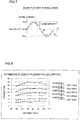
- Fig. 5 shows a signal curve 70 obtained by a fringe scanning method.
- X-ray imaging is performed by stepping one of the first grating 3, the second grating 4, and the third grating 2 a plurality of times along a grating plane, and the inside of the subject T is imaged based on a plurality of Moire images obtained by X-ray imaging for each step.
- the signal curve 70 is a curve obtained by normalizing a pixel value (signal value) of each step in the single detection element 5a of the detector 5. That is, the signal curve 70 is a signal curve that represents pixel value changes in the detector 5.
- the pixel value is not limited to the pixel value of each step in the single detection element 5a of the detector 5.
- a characteristic value an average value or the center value of a histogram, for example
- Fig. 6 shows a signal curve 80 obtained by a method using a Fourier transform method.
- X-ray imaging is performed in a state in which one of the first grating 3, the second grating 4, and the third grating 2 is rotated in the grating plane, and the inside of the subject T is imaged based on a single Moire image obtained by this X-ray imaging.
- the signal curve 80 is a curve obtained by normalizing a pixel value of each of the detection elements 5a arrayed in a row, for example. That is, the signal curve 80 is a signal curve that represents pixel value changes in the detector 5.
- the pixel value is not limited to the pixel value of each of the detection elements 5a arrayed in a row.
- a characteristic value an average value or the center value of a histogram, for example
- each of pixel blocks arrayed in a row may be used as the pixel value.
- the signal curves 70 and 80 that represent pixel value changes are obtained by the fringe scanning method and the method using the Fourier transform method, for example.
- the first grating 3, the second grating 4, and the third grating 2 are arranged so as to further satisfy the conditions of the following formula (12).
- C is a difference between a maximum value (Imax) and a minimum value (Imin) of a signal curve 90 that represents pixel value changes.
- r is the noise intensity of the signal curve 90.
- the signal curve 90 indicates a concept including the signal curves 70 and 80.
- the formula (12) defines a condition in which the intensity r of a noise 91 is smaller than the difference C between Imax and Imin. If the intensity r of the noise 91 is larger than the difference C between Imax and Imin, the signal curve 90 is buried in the noise 91.
- the noise 91 includes a quantum noise determined from the dose of X-rays and the electrical noise of the detector 5.
- the first grating 3, the second grating 4, and the third grating 2 are arranged so as to further satisfy the conditions of the following formula (13).
- ⁇ r Imax + Imin 2
- the visibility in the formula (13) is defined by the following formula (15), or when the following formula (16) is defined, the visibility in the formula (13) is defined by the following formula (17).
- ⁇ k 1 M I k x y
- v in the formula (15) is visibility (i.e. v in the formula (13)).
- Imax in the formula (15) is the maximum value of the signal curve 90.
- Imin in the formula (15) is the minimum value of the signal curve 90.
- V(x, y) in the formulas (16) and (17) is visibility (i.e. v in the formula (13)) .
- x and y of V(x, y) are coordinate positions in the plane orthogonal to the X-ray irradiation axis direction (direction Z) in the second grating 4
- x is a coordinate position in the direction X
- y is a coordinate position in the direction Y.
- k in the formulas (16) and (17) is the number of steps of the signal curve 70 shown in Fig. 5 .
- I k (x, y) in the formulas (16) and (17) is a signal value (signal intensity) at the number of steps k.
- M in the formulas (16) and (17) is the total number of steps of the signal curve 70 (i.e. eight times in Fig. 5 ).
- V(x, y) in the formulas (16) and (17) is visibility (i.e. v in the formula (13)). Furthermore, x and y of V(x, y) are coordinate positions in the plane orthogonal to the X-ray irradiation axis direction (direction Z) in the second grating 4, x is a coordinate position in the direction X, and y is a coordinate position in the direction Y.
- k in the formulas (16) and (17) is the detection element number of the signal curve 80 shown in Fig. 6 .
- I k (x, y) in the formulas (16) and (17) is a signal value (signal intensity) at the detection element number k.
- M in the formulas (16) and (17) is the total number of detection elements of the signal curve 80 (i.e. eight in Fig. 6 ).
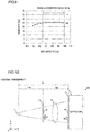
- the results of visibility measurement performed to confirm the effect of the first embodiment are shown with reference to Fig. 8 .
- the pitch d0 of the third grating 2 was set to 10 ⁇ m
- the pitch d1 of the first grating 3 was set to 5 ⁇ m
- the pitch d2 of the second grating 4 was set to 10 ⁇ m
- the first grating 3, the second grating 4, and the third grating 2 were arranged so as to satisfy the condition of the above formula (9).
- the visibility was measured by changing the distance R between the third grating 2 and the second grating 4, the tube voltage of the X-ray source 1, and the tube current of the X-ray source 1. The visibility was calculated using the above formula (17).
- Condition 1 when the tube voltage of the X-ray source 1 was 30 kV and the tube current of the X-ray source 1 was 170 ⁇ A, the distance R was varied between about 50 cm and about 105 cm. In Condition 1, even when the distance R is varied between about 50 cm and about 105 cm, the value of the visibility is generally stable between about 29% and about 35%. Therefore, in Condition 1, it was possible to obtain the stable visibility in the irradiation axis direction.
- Condition 2 when the tube voltage of the X-ray source 1 was 35 kV and the tube current of the X-ray source 1 was 210 ⁇ A, the distance R was varied between about 50 cm and about 105 cm. In Condition 2, even when the distance R is varied between about 50 cm and about 105 cm, the value of the visibility is generally stable between about 22% and about 26%. Therefore, in Condition 2, it was possible to obtain the stable visibility in the irradiation axis direction.
- Condition 3 when the tube voltage of the X-ray source 1 was 40 kV and the tube current of the X-ray source 1 was 250 ⁇ A, the distance R was varied between about 50 cm and about 105 cm. In Condition 3, even when the distance R is varied between about 50 cm and about 105 cm, the value of the visibility is generally stable between about 16% and about 19%. Therefore, in Condition 3, it was possible to obtain the stable visibility in the irradiation axis direction.
- Condition 4 when the tube voltage of the X-ray source 1 was 50 kV and the tube current of the X-ray source 1 was 200 ⁇ A, the distance R was varied between about 50 cm and about 105 cm. In Condition 4, even when the distance R is varied between about 50 cm and about 105 cm, the value of the visibility is generally stable between about 8% and about 11%. Therefore, in Condition 4, it was possible to obtain the stable visibility in the irradiation axis direction.
- Condition 5 when the tube voltage of the X-ray source 1 was 60 kV and the tube current of the X-ray source 1 was 160 ⁇ A, the distance R was varied between about 50 cm and about 105 cm. In Condition 5, even when the distance R is varied between about 50 cm and about 105 cm, the value of the visibility is generally stable between about 6% and about 8%. Therefore, in Condition 5, it was possible to obtain the stable visibility in the irradiation axis direction.
- the first grating 3, the second grating 4, and the third grating 2 are arranged so as to satisfy the condition of the above formula (9) such that the stable visibility is obtained in the irradiation axis direction even when the tube voltage of the X-ray source 1 and the tube current of the X-ray source 1 are varied. That is, it has been confirmable that the condition of the above formula (9) is satisfied such that the first grating 3, the second grating 4, and the third grating 2 can be arranged at positions suitable for imaging the subject T even when the continuous X-rays are used.
- Fig. 9 shows the case of applying this condition in Condition 2 in Fig. 8 .
- the first grating 3, the second grating 4, and the third grating 2 are arranged so as to satisfy the condition of the formula (9).
- the first grating 3, the second grating 4, and the third grating 2 can be arranged without using characteristics such as the wavelength of the X-ray source 1. Consequently, even when the continuous X-rays are used, the arrangement of the first grating 3, the second grating 4, and the third grating 2 can be determined.
- the third grating 2 is provided such that the continuous X-rays that have passed through the third grating 2 are allowed to function as the plurality of X-ray sources (line light sources 21 and 22, for example).
- a plurality of self-images of the first grating 3 can be formed by the plurality of X-ray sources.
- the first grating 3, the second grating 4, and the third grating 2 are arranged so as to satisfy the condition of the above formula (9) such that the first grating 3, the second grating 4, and the third grating 2 can be arranged so as to substantially match the pitch of each of the self-images of the first grating 3 with the pitch d2 of the second grating 4. Consequently, the first grating 3, the second grating 4, and the third grating 2 can be arranged at positions suitable for imaging the subject T.
- the first grating 3, the second grating 4, and the third grating 2 are arranged so as to satisfy the condition of the above formula (12).
- the first grating 3, the second grating 4, and the third grating 2 can be arranged so as to reduce noise. Consequently, a captured image with high visibility can be easily obtained.
- the first grating 3, the second grating 4, and the third grating 2 are arranged so as to further satisfy the condition of the formula (13).
- the first grating 3, the second grating 4, and the third grating 2 can be arranged so as to reduce noise.
- the visibility in the formula (13) is defined by the formula (15), or when the formula (16) is defined, the visibility in the formula (13) is defined by the formula (17) .
- an X-ray phase contrast imaging apparatus 200 according to the second embodiment of the present invention is different from the X-ray phase contrast imaging apparatus 100 according to the aforementioned first embodiment in that the third grating 2 according to the aforementioned first embodiment is not provided.
- an X-ray source 1, a first grating 3, and a second grating 4 are arranged so as to satisfy the condition of the following formula (20).
- R 1 : d 1 R : d 2
- d1 is the pitch of the first grating 3
- d2 is the pitch of the second grating 4
- R1 is a distance between the X-ray source 1 and the first grating 3.
- R2 is a distance between the first grating 3 and the second grating 4, and R is R1 + R2.
- the formula (20) is the same formula as the formula (10) according to the aforementioned first embodiment. That is, the formula (20) defines the arrangement of the first grating 3 and the second grating 4 so as to substantially match the pitch of the self-image of the first grating 3 with the pitch d2 of the second grating 4.
- the formula (20) can be obtained from the geometric arrangement of the X-ray source 1, the first grating 3, and the second grating 4. This point is analogous to that in the first embodiment when the line light source 21 according to the aforementioned first embodiment is replaced with the X-ray source 1, and thus description thereof is omitted.
- the X-ray source 1, the first grating 3, and the second grating 4 are arranged so as to satisfy the above formulas (12) and (13) similarly to the aforementioned first embodiment.
- the X-ray source 1, the first grating 3, and the second grating 4 are arranged so as to satisfy the condition of the formula (20).
- the X-ray source 1, the first grating 3, and the second grating 4 can be arranged without using characteristics such as the wavelength of the X-ray source 1. Consequently, even when continuous X-rays are used, the arrangement of the X-ray source 1, the first grating 3, and the second grating 4 can be determined.
- the X-ray source 1, the first grating 3, and the second grating 4 are arranged so as to satisfy the condition of the above formula (20) such that the X-ray source 1, the first grating 3, and the second grating 4 can be arranged so as to substantially match the pitch of the self-image of the first grating 3 with the pitch d2 of the second grating 4. Consequently, the X-ray source 1, the first grating 3, and the second grating 4 can be arranged at positions suitable for imaging a subject T.
- the X-ray source 1, the first grating 3, and the second grating 4 are arranged so as to satisfy the condition of the above formula (12) such that the X-ray source 1, the first grating 3, and the second grating 4 can be arranged so as to reduce noise. Consequently, a captured image with high visibility can be easily obtained.
- the present invention is not restricted to this.
- the subject may not be placed on the side of the first grating closer to the detector.
- the subject may be placed on the side of the first grating opposite to the detector.
- the present invention is not restricted to this.
- the first grating, the second grating, and the third grating may not be arranged so as to satisfy the conditions of the formulas (12) and (13).
- the X-ray source, the first grating, and the second grating may not be arranged so as to satisfy the conditions of the formulas (12) and (13).
- the first grating is a diffraction grating (phase grating) that changes the phase of the passing X-rays
- the present invention is not restricted to this.
- the first grating may be a diffraction grating (absorption grating) that changes the intensity of the passing X-rays.
Landscapes
- Health & Medical Sciences (AREA)
- Life Sciences & Earth Sciences (AREA)
- Engineering & Computer Science (AREA)
- Medical Informatics (AREA)
- Pathology (AREA)
- General Health & Medical Sciences (AREA)
- Physics & Mathematics (AREA)
- Radiology & Medical Imaging (AREA)
- Nuclear Medicine, Radiotherapy & Molecular Imaging (AREA)
- Biomedical Technology (AREA)
- Public Health (AREA)
- High Energy & Nuclear Physics (AREA)
- Biophysics (AREA)
- Heart & Thoracic Surgery (AREA)
- Molecular Biology (AREA)
- Surgery (AREA)
- Animal Behavior & Ethology (AREA)
- Veterinary Medicine (AREA)
- Optics & Photonics (AREA)
- Chemical & Material Sciences (AREA)
- Analytical Chemistry (AREA)
- Biochemistry (AREA)
- General Physics & Mathematics (AREA)
- Immunology (AREA)
- Computer Vision & Pattern Recognition (AREA)
- Apparatus For Radiation Diagnosis (AREA)
- Analysing Materials By The Use Of Radiation (AREA)
Applications Claiming Priority (2)
| Application Number | Priority Date | Filing Date | Title |
|---|---|---|---|
| JP2016148428 | 2016-07-28 | ||
| PCT/JP2017/025143 WO2018020999A1 (ja) | 2016-07-28 | 2017-07-10 | X線位相差撮像装置 |
Publications (2)
| Publication Number | Publication Date |
|---|---|
| EP3492016A1 true EP3492016A1 (de) | 2019-06-05 |
| EP3492016A4 EP3492016A4 (de) | 2020-03-25 |
Family
ID=61016471
Family Applications (1)
| Application Number | Title | Priority Date | Filing Date |
|---|---|---|---|
| EP17834007.1A Withdrawn EP3492016A4 (de) | 2016-07-28 | 2017-07-10 | Vorrichtung zur aufnahme von röntgenphasendifferenzbildern |
Country Status (5)
| Country | Link |
|---|---|
| US (1) | US10772592B2 (de) |
| EP (1) | EP3492016A4 (de) |
| JP (1) | JP6626578B2 (de) |
| CN (1) | CN109561864B (de) |
| WO (1) | WO2018020999A1 (de) |
Family Cites Families (17)
| Publication number | Priority date | Publication date | Assignee | Title |
|---|---|---|---|---|
| EP1447046A1 (de) * | 2003-02-14 | 2004-08-18 | Paul Scherrer Institut | Vorrichtung und Verfahren zur Aufnahme von Phasenkontrast-Röntgenbildern |
| CN102802529B (zh) * | 2009-06-16 | 2015-09-16 | 皇家飞利浦电子股份有限公司 | 用于微分相衬成像的校正方法 |
| JP5702586B2 (ja) * | 2010-02-04 | 2015-04-15 | 富士フイルム株式会社 | 放射線撮影システム |
| JP5438649B2 (ja) * | 2010-03-26 | 2014-03-12 | 富士フイルム株式会社 | 放射線撮影システム及び位置ずれ判定方法 |
| JP5378335B2 (ja) * | 2010-03-26 | 2013-12-25 | 富士フイルム株式会社 | 放射線撮影システム |
| JP2011224329A (ja) * | 2010-03-30 | 2011-11-10 | Fujifilm Corp | 放射線撮影システム及び方法 |
| JP5548085B2 (ja) * | 2010-03-30 | 2014-07-16 | 富士フイルム株式会社 | 回折格子の調整方法 |
| CN102221565B (zh) * | 2010-04-19 | 2013-06-12 | 清华大学 | X射线源光栅步进成像系统与成像方法 |
| JP5601909B2 (ja) | 2010-07-06 | 2014-10-08 | 国立大学法人 東京大学 | X線撮像装置及びこれを用いるx線撮像方法 |
| JP2014012029A (ja) * | 2010-10-27 | 2014-01-23 | Fujifilm Corp | 放射線撮影システム及び画像処理方法 |
| WO2012057023A1 (ja) * | 2010-10-28 | 2012-05-03 | 富士フイルム株式会社 | 放射線画像撮影システム及びその制御方法 |
| EP2633813B1 (de) * | 2010-10-29 | 2015-02-25 | FUJIFILM Corporation | Phasenkontrast-strahlungsabbildungsvorrichtung |
| JP2012135612A (ja) * | 2010-12-07 | 2012-07-19 | Fujifilm Corp | 放射線位相画像撮影方法および装置 |
| JP5475737B2 (ja) * | 2011-10-04 | 2014-04-16 | 富士フイルム株式会社 | 放射線撮影装置及び画像処理方法 |
| CN109115816A (zh) * | 2014-02-14 | 2019-01-01 | 佳能株式会社 | X射线Talbot干涉仪和X射线Talbot干涉仪系统 |
| JP2015227784A (ja) * | 2014-05-30 | 2015-12-17 | キヤノン株式会社 | 干渉計 |
| JP6673188B2 (ja) * | 2016-12-26 | 2020-03-25 | 株式会社島津製作所 | X線位相撮影装置 |
-
2017
- 2017-07-10 JP JP2018529484A patent/JP6626578B2/ja active Active
- 2017-07-10 WO PCT/JP2017/025143 patent/WO2018020999A1/ja not_active Ceased
- 2017-07-10 US US16/321,297 patent/US10772592B2/en active Active
- 2017-07-10 EP EP17834007.1A patent/EP3492016A4/de not_active Withdrawn
- 2017-07-10 CN CN201780046916.2A patent/CN109561864B/zh active Active
Also Published As
| Publication number | Publication date |
|---|---|
| JPWO2018020999A1 (ja) | 2019-05-09 |
| CN109561864A (zh) | 2019-04-02 |
| EP3492016A4 (de) | 2020-03-25 |
| US10772592B2 (en) | 2020-09-15 |
| WO2018020999A1 (ja) | 2018-02-01 |
| CN109561864B (zh) | 2022-05-17 |
| US20190167219A1 (en) | 2019-06-06 |
| JP6626578B2 (ja) | 2019-12-25 |
Similar Documents
| Publication | Publication Date | Title |
|---|---|---|
| CN108720857B (zh) | X射线相位差摄像系统 | |
| EP3488783A1 (de) | Röntgenphasendifferenzabbildungsvorrichtung | |
| EP2884899B1 (de) | Ausrichten der source-grating-zu-phase-grating-distanz für phasenabstimmung vielfacher ordnung bei der differenzialphasenkontrastbildgebung | |
| US10267752B2 (en) | X-ray phase-contrast imaging system and imaging method | |
| EP3346260B1 (de) | Vorrichtung zur erzeugung von röntgenbildern | |
| US9269471B2 (en) | Differential phase-contrast imaging with circular gratings | |
| US8520799B2 (en) | Analysis method, radiation imaging apparatus using analysis method, and analysis program for executing analysis method | |
| US9105369B2 (en) | Differential phase-contrast imaging with improved sampling | |
| EP2878265B1 (de) | Medizinisches Abbildungssystem | |
| EP3383273B1 (de) | Vorrichtung zur röntgenstrahlabbildung eines objekts | |
| WO2011102247A2 (en) | X-ray imaging method and x-ray imaging apparatus | |
| US20210148839A1 (en) | X-ray phase image capturing system | |
| EP3112850B1 (de) | Röntgenbildgebungsvorrichtung und röntgenbildgebungsverfahren | |
| US20150355112A1 (en) | Computation apparatus, program, and x-ray imaging system | |
| US20140198895A1 (en) | Medical imaging system | |
| US20150320372A1 (en) | Radiation imaging apparatus | |
| US20150310609A1 (en) | Systems and methods for regularized fourier analysis in x-ray phase contrast imaging | |
| RU2708816C2 (ru) | Детектор и система визуализации для рентгеновской фазово-контрастной визуализации томосинтеза | |
| EP3492016A1 (de) | Vorrichtung zur aufnahme von röntgenphasendifferenzbildern | |
| US20200249178A1 (en) | Phase contrast x-ray imaging system | |
| JP2017093496A (ja) | 撮像装置 | |
| JP2012024554A (ja) | 放射線位相画像撮影装置 | |
| US20220218296A1 (en) | Application for x-ray dark-field and/or x-ray phase contrast imaging using stepping and moiré imaging | |
| Gang et al. | Implementation and assessment of dynamic fluence field modulation with multiple aperture devices | |
| Ramadevi et al. | Position calibration methodology for scanning sky monitor for ASTROSAT |
Legal Events
| Date | Code | Title | Description |
|---|---|---|---|
| PUAI | Public reference made under article 153(3) epc to a published international application that has entered the european phase |
Free format text: ORIGINAL CODE: 0009012 |
|
| 17P | Request for examination filed |
Effective date: 20190214 |
|
| AK | Designated contracting states |
Kind code of ref document: A1 Designated state(s): AL AT BE BG CH CY CZ DE DK EE ES FI FR GB GR HR HU IE IS IT LI LT LU LV MC MK MT NL NO PL PT RO RS SE SI SK SM TR |
|
| AX | Request for extension of the european patent |
Extension state: BA ME |
|
| DAV | Request for validation of the european patent (deleted) | ||
| DAX | Request for extension of the european patent (deleted) | ||
| A4 | Supplementary search report drawn up and despatched |
Effective date: 20200225 |
|
| RIC1 | Information provided on ipc code assigned before grant |
Ipc: A61B 6/00 20060101AFI20200219BHEP Ipc: G01N 23/04 20180101ALI20200219BHEP |
|
| STAA | Information on the status of an ep patent application or granted ep patent |
Free format text: STATUS: THE APPLICATION HAS BEEN WITHDRAWN |
|
| 18W | Application withdrawn |
Effective date: 20200915 |