EP3491817B1 - Dispositif de traitement de signal, procédé de traitement de signal et programme - Google Patents
Dispositif de traitement de signal, procédé de traitement de signal et programme Download PDFInfo
- Publication number
- EP3491817B1 EP3491817B1 EP17826592.2A EP17826592A EP3491817B1 EP 3491817 B1 EP3491817 B1 EP 3491817B1 EP 17826592 A EP17826592 A EP 17826592A EP 3491817 B1 EP3491817 B1 EP 3491817B1
- Authority
- EP
- European Patent Office
- Prior art keywords
- images
- image
- polarization
- circuitry
- unit
- Prior art date
- Legal status (The legal status is an assumption and is not a legal conclusion. Google has not performed a legal analysis and makes no representation as to the accuracy of the status listed.)
- Not-in-force
Links
- 238000012545 processing Methods 0.000 title claims description 228
- 238000003672 processing method Methods 0.000 title description 4
- 238000001514 detection method Methods 0.000 claims description 248
- 230000010287 polarization Effects 0.000 claims description 174
- 238000007689 inspection Methods 0.000 claims description 62
- 238000000605 extraction Methods 0.000 claims description 29
- 239000002131 composite material Substances 0.000 claims description 22
- 238000000034 method Methods 0.000 claims description 20
- 238000004458 analytical method Methods 0.000 claims description 16
- 230000004044 response Effects 0.000 claims description 7
- 238000010586 diagram Methods 0.000 description 14
- 238000004891 communication Methods 0.000 description 13
- 238000005516 engineering process Methods 0.000 description 13
- 239000000284 extract Substances 0.000 description 10
- 238000007405 data analysis Methods 0.000 description 8
- 238000012986 modification Methods 0.000 description 8
- 230000004048 modification Effects 0.000 description 8
- 230000033228 biological regulation Effects 0.000 description 7
- 239000011159 matrix material Substances 0.000 description 6
- 238000003384 imaging method Methods 0.000 description 5
- 230000005540 biological transmission Effects 0.000 description 4
- 238000012880 independent component analysis Methods 0.000 description 4
- 230000003287 optical effect Effects 0.000 description 4
- 230000000694 effects Effects 0.000 description 3
- 230000006870 function Effects 0.000 description 2
- 238000010191 image analysis Methods 0.000 description 2
- 238000005259 measurement Methods 0.000 description 2
- 239000004065 semiconductor Substances 0.000 description 2
- 244000025254 Cannabis sativa Species 0.000 description 1
- 241000196324 Embryophyta Species 0.000 description 1
- 230000001133 acceleration Effects 0.000 description 1
- 239000003086 colorant Substances 0.000 description 1
- 239000000356 contaminant Substances 0.000 description 1
- 230000001419 dependent effect Effects 0.000 description 1
- 238000007599 discharging Methods 0.000 description 1
- 239000006185 dispersion Substances 0.000 description 1
- 239000011521 glass Substances 0.000 description 1
- 229910052500 inorganic mineral Inorganic materials 0.000 description 1
- 238000001000 micrograph Methods 0.000 description 1
- 239000011707 mineral Substances 0.000 description 1
- 238000002156 mixing Methods 0.000 description 1
- 239000011347 resin Substances 0.000 description 1
- 229920005989 resin Polymers 0.000 description 1
- 150000003839 salts Chemical class 0.000 description 1
- 239000000758 substrate Substances 0.000 description 1
Images


Classifications
-
- G—PHYSICS
- G06—COMPUTING; CALCULATING OR COUNTING
- G06T—IMAGE DATA PROCESSING OR GENERATION, IN GENERAL
- G06T3/00—Geometric image transformations in the plane of the image
- G06T3/40—Scaling of whole images or parts thereof, e.g. expanding or contracting
- G06T3/4038—Image mosaicing, e.g. composing plane images from plane sub-images
-
- G—PHYSICS
- G06—COMPUTING; CALCULATING OR COUNTING
- G06T—IMAGE DATA PROCESSING OR GENERATION, IN GENERAL
- G06T5/00—Image enhancement or restoration
- G06T5/40—Image enhancement or restoration using histogram techniques
-
- G—PHYSICS
- G06—COMPUTING; CALCULATING OR COUNTING
- G06T—IMAGE DATA PROCESSING OR GENERATION, IN GENERAL
- G06T7/00—Image analysis
- G06T7/30—Determination of transform parameters for the alignment of images, i.e. image registration
- G06T7/33—Determination of transform parameters for the alignment of images, i.e. image registration using feature-based methods
-
- H—ELECTRICITY
- H04—ELECTRIC COMMUNICATION TECHNIQUE
- H04N—PICTORIAL COMMUNICATION, e.g. TELEVISION
- H04N23/00—Cameras or camera modules comprising electronic image sensors; Control thereof
- H04N23/60—Control of cameras or camera modules
- H04N23/698—Control of cameras or camera modules for achieving an enlarged field of view, e.g. panoramic image capture
-
- H—ELECTRICITY
- H04—ELECTRIC COMMUNICATION TECHNIQUE
- H04N—PICTORIAL COMMUNICATION, e.g. TELEVISION
- H04N23/00—Cameras or camera modules comprising electronic image sensors; Control thereof
- H04N23/80—Camera processing pipelines; Components thereof
-
- H—ELECTRICITY
- H04—ELECTRIC COMMUNICATION TECHNIQUE
- H04N—PICTORIAL COMMUNICATION, e.g. TELEVISION
- H04N23/00—Cameras or camera modules comprising electronic image sensors; Control thereof
- H04N23/95—Computational photography systems, e.g. light-field imaging systems
- H04N23/951—Computational photography systems, e.g. light-field imaging systems by using two or more images to influence resolution, frame rate or aspect ratio
-
- H—ELECTRICITY
- H04—ELECTRIC COMMUNICATION TECHNIQUE
- H04N—PICTORIAL COMMUNICATION, e.g. TELEVISION
- H04N25/00—Circuitry of solid-state image sensors [SSIS]; Control thereof
- H04N25/10—Circuitry of solid-state image sensors [SSIS]; Control thereof for transforming different wavelengths into image signals
- H04N25/11—Arrangement of colour filter arrays [CFA]; Filter mosaics
- H04N25/13—Arrangement of colour filter arrays [CFA]; Filter mosaics characterised by the spectral characteristics of the filter elements
- H04N25/134—Arrangement of colour filter arrays [CFA]; Filter mosaics characterised by the spectral characteristics of the filter elements based on three different wavelength filter elements
-
- G—PHYSICS
- G06—COMPUTING; CALCULATING OR COUNTING
- G06T—IMAGE DATA PROCESSING OR GENERATION, IN GENERAL
- G06T2207/00—Indexing scheme for image analysis or image enhancement
- G06T2207/10—Image acquisition modality
- G06T2207/10024—Color image
-
- G—PHYSICS
- G06—COMPUTING; CALCULATING OR COUNTING
- G06T—IMAGE DATA PROCESSING OR GENERATION, IN GENERAL
- G06T2207/00—Indexing scheme for image analysis or image enhancement
- G06T2207/10—Image acquisition modality
- G06T2207/10048—Infrared image
-
- G—PHYSICS
- G06—COMPUTING; CALCULATING OR COUNTING
- G06T—IMAGE DATA PROCESSING OR GENERATION, IN GENERAL
- G06T2207/00—Indexing scheme for image analysis or image enhancement
- G06T2207/10—Image acquisition modality
- G06T2207/10141—Special mode during image acquisition
- G06T2207/10152—Varying illumination
-
- G—PHYSICS
- G06—COMPUTING; CALCULATING OR COUNTING
- G06T—IMAGE DATA PROCESSING OR GENERATION, IN GENERAL
- G06T2207/00—Indexing scheme for image analysis or image enhancement
- G06T2207/20—Special algorithmic details
- G06T2207/20021—Dividing image into blocks, subimages or windows
-
- G—PHYSICS
- G06—COMPUTING; CALCULATING OR COUNTING
- G06T—IMAGE DATA PROCESSING OR GENERATION, IN GENERAL
- G06T2207/00—Indexing scheme for image analysis or image enhancement
- G06T2207/20—Special algorithmic details
- G06T2207/20212—Image combination
- G06T2207/20221—Image fusion; Image merging
Definitions
- the present disclosure relates to a signal processing device, a signal processing method, and a program, and particularly relates to a signal processing device, a signal processing method, and a program, capable of preferably performing desired inspection.
- NDVI normalized difference vegetation index
- the raising state of a crop is inspected with an image acquired by capturing an object to be inspected with dispersion with the components of near-infrared light and red light, for a purpose in the fields of remote sensing and precision agriculture.
- a polarization imager including various polarization filters arranged for each pixel, can acquire an image having a characteristic corresponding to a polarization direction.
- the polarization imager separates the pixels in a light-receiving surface, into a plurality of polarization directions and then generates an image for each polarization direction so that resolution degrades (in a case where four polarization directions are used, for example, the resolution degrades to be 1/4).
- PTL 1 discloses the following image capturing device.
- An actuator shifts, per pixel unit, a polarizer array including polarizers (a polarization filter for each pixel) arranged in an array form so that a plurality of images is captured and then is processed to retain resolution.
- PTL2 discloses discloses a processing device comprising:circuitry configured to acquire a plurality of images captured in a time series by an image sensor, each of the plurality of images is based on light in one predetermined polarization direction and in one of a plurality of predetermined wavelength bands; and stitch together at least a part of the plurality of images corresponding a single predetermined wavelength band from the plurality of predetermined wavelength bands to generate a composite image.
- PTL3 discloses a processing device comprising circuitry configured to acquire a plurality of images captured in a time series by an image sensor, each of the plurality of images is based on light in one of a plurality of predetermined polarization directions and in one of a plurality of predetermined wavelength bands.
- a method of acquiring an image having a wide range with high resolution by stitching a plurality of images that has been consecutively captured, being moved, has been generally known (referred to as image stitching).
- image stitching A method of acquiring the image having the wide range by stitching the plurality of images and the method of retaining the resolution by using the image capturing device disclosed in PTL 1 above are difficult to make compatible with each other. Therefore, for example, there is a need to preferably perform inspection of vegetation with the normalized difference vegetation index by acquiring an image having a wide range with high resolution even when the polarization imager is used.
- the present disclosure has been made in consideration of the above situation, and is to allow desired inspection to be preferably performed.
- a processing device including circuitry configured to acquire a plurality of images captured in a time series by an image sensor, each of the plurality of images is based on light in one of a plurality of predetermined polarization directions and in one of a plurality of predetermined wavelength bands.
- the circuitry is further configured to stitch together at least a part of the plurality of images corresponding to a single polarization direction and a single predetermined wavelength band from the plurality of predetermined wavelength bands to generate a composite image.
- a method that includes acquiring, with a circuitry, a plurality of images captured in a time series by an image sensor , each of the plurality of images is based on light in one of a plurality of predetermined polarization directions and in one of a plurality of predetermined wavelength bands.
- the method further includes stitching together, with the circuitry, at least a part of the plurality of images corresponding to a single polarization direction and a single predetermined wavelength band from the plurality of predetermined wavelength bands to generate a composite image.
- a non-transitory computer-readable medium storing a program for causing an electronic processor to execute a set of operations, the set of operations includes acquiring a plurality of images captured in a time series by an image sensor , each of the plurality of images is based on light in one of a plurality of predetermined polarization directions and in one of a plurality of predetermined wavelength bands.
- the set of operations further includes stitching together at least a part of the plurality of images corresponding to a single polarization direction and a single predetermined wavelength band from the plurality of predetermined wavelength bands to generate a composite image.
- desired inspection can be preferably performed.
- Fig. 1 is a block diagram of an exemplary configuration of one embodiment of a vegetation inspection device to which the present technology has been applied.
- the vegetation inspection device 11 includes a detection device 12 and a signal processing device 13, and is used to inspect a raising state, such as the vegetation state or the activity of an object to be inspected, such as grass or a crop.
- the detection device 12 is, for example, an image sensor including a plurality of pixels (sensor elements) arranged in a matrix form on a light-receiving surface, and detects, for each pixel, the intensity of light reflected from a surface of the object to be inspected so that an image of the object to be inspected can be acquired.
- the detection device 12 includes each pixel that detects the light in a polarization direction and in a specific wavelength band.
- the detection device 12 includes a polarization filter that transmits the light in a predetermined polarization direction and an optical filter that transmits the light in a predetermined wavelength band, layered to a sensor substrate including photodiodes formed, the photodiodes included in the pixels.
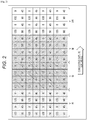
- each small square illustrated in Fig. 2 represents a pixel, and a numeral added to each pixel represents the angle of a polarization direction.
- a polarization direction is set every 45°, and four pixels including polarization directions set at 0°, 45°, 90°, and 135° are arranged to be adjacent to each other in a 2 ⁇ 2 matrix form.
- the detection device 12 includes the four pixels as a set and the pixels are arranged for each set. Note that, the detection device 12 is not limited to the detection of the light in the four polarization directions, and at least detects the light in at least three polarization directions with three pixels arranged to be adjacent to each other.
- the detection device 12 includes pixels that detect the light in the same wavelength band, integrally arranged for each detection area of wavelength bands. That is, as illustrated in Fig. 2 , the detection device 12 includes pixels that detect the light in a red wavelength band, arranged in a red detection area R, pixels that detect the light in a green wavelength band, arranged in a green detection area G, pixels that detect the light in a blue wavelength band, arranged in a blue detection area B, and pixels that detect the light in a near-infrared wavelength band, arranged in a near-infrared detection area IR.
- the red detection area R, the green detection area G, the blue detection area B, and the near-infrared detection area IR are formed to have an elongate and rectangular shape in a column direction (an upper and lower direction of Fig. 2 ), and the areas are arranged in parallel in a row direction (a left and right direction of Fig. 2 ).
- the detection device 12 includes the light-receiving surface including the plurality of pixels arranged, divided into four sections including the red detection area R, the green detection area G, the blue detection area B, and the near-infrared detection area IR.
- the detection device 12 can acquire an image for each wavelength band, divided to have the elongate and rectangular shape in the column direction (hereinafter, appropriately referred to as a divided image) through each of the red detection area R, the green detection area G, the blue detection area B, and the near-infrared detection area IR, by one time of exposure.
- the detection device 12 can consecutively acquire a plurality of images at a high speed, and the plurality of images is used for inspection of the object to be inspected.
- the row direction of Fig. 2 is defined as a moving direction of the detection device 12 in order to allow the red detection area R, the green detection area G, the blue detection area B, and the near-infrared detection area IR to sequentially scan the object to be inspected.
- the vegetation inspection device 11 moves, for example, at a moving speed to superimpose divided images consecutively acquired through each of the red detection area R, the green detection area G, the blue detection area B, and the near-infrared detection area IR, by a predetermined width or more in the row direction, in inspecting the object to be inspected.
- the detection device 12 detects the light in the four polarization directions with the pixels, and can acquire the divided images in each wavelength band of the red detection area R, the green detection area G, the blue detection area B, and the near-infrared detection area IR. Then, the detection device 12 inputs, as input image data, image data including a pixel value in response to the intensity of the light in each polarization direction in each wavelength band, into the signal processing device 13.
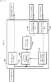
- the signal processing device 13 includes, as illustrated in Fig. 1 , an image data analysis unit 21, an image processing selection unit 22, a first image processing unit 23a, a second image processing unit 23b, and a stitching processing unit 24.
- the image data analysis unit 21 performs analysis to the input image data input from the detection device 12, and supplies an analysis result thereof to the image processing selection unit 22. For example, the image data analysis unit 21 acquires a histogram of pixel values in the input image data of one image that can be acquired by the detection device 12, and acquires the number of pixels having a pixel value smaller than a specific reference value for each detection area of the wavelength bands so that an analysis result can be acquired.
- the image processing selection unit 22 selects any one of image processing in the first image processing unit 23a and image processing in the second image processing unit 23b so as to supply the input image data input from the detection device 12, in accordance with the analysis result supplied from the image data analysis unit 21. For example, in a case where the image appears in the detection areas of all the wavelength bands, the image processing selection unit 22 selects the image processing in the first image processing unit 23a, and in a case where no image appears in the detection area of any of the wavelength bands, the image processing selection unit 22 selects the image processing in the second image processing unit 23b.
- the image processing selection unit 22 supplies the input image data to the first image processing unit 23a in a case where the analysis result of the input image data indicates that the number of pixels having a pixel value smaller than the specific reference value is the threshold value or more in the detection areas of all the wavelength bands. Meanwhile, the image processing selection unit 22 supplies the input image data to the second image processing unit 23b in a case where the analysis result of the input image data indicates that the number of pixels having a pixel value smaller than the specific reference value is less than the threshold value in the detection area of any of the wavelength bands.
- the first image processing unit 23a and the second image processing unit 23b individually perform the image processing to the input image data, as to be described later with reference to Figs. 4 and 5 . Then, the first image processing unit 23a and the second image processing unit 23b each supply divided image data including the input image data divided for each wavelength band and coordinate data indicating the coordinates of a feature point on the image acquired by the detection device 12, to the stitching processing unit 24.
- any one of the first image processing unit 23a and the second image processing unit 23b sequentially supplies the divided image data and the coordinate data to the stitching processing unit 24 every time the detection device 12 supplies the input image data of one image to the signal processing device 13. Then, the stitching processing unit 24 stitches divided images that have been consecutively supplied, for each wavelength band, so as to generate an output image indicated with the pixel values in each wavelength band. That is, the stitching processing unit 24 composites portions including a common point captured between adjacent divided images, to be superimposed on the basis of the coordinate data indicating the feature point on the image, and then generates an image larger than an image that can be captured by one time of exposure in the detection device 12.
- the stitching processing unit 24 estimates a corresponding feature point between the divided images, performs image processing of moving or deforming the divided images to superimpose the feature point of each divided image, and then performs image processing of blending the pixel values of portions being superimposed of the divided images each including the feature point in agreement with the other.
- the stitching processing unit 24 can generate one output image including the object to be inspected captured with a wide range and high resolution. Then, the stitching processing unit 24 outputs data included in the output image having a wide range and high resolution (an image including a range captured wider than one image acquired by the detection device 12) as output image data.
- a plurality of images (four images in the example of Fig. 3 ) consecutively acquired by the detection device 12, are illustrated in descending order at a left end of Fig. 3 .
- a first image includes a divided image R1 corresponding to the red detection area R, a divided image G1 corresponding to the green detection area G, a divided image B1 corresponding to the blue detection area B, and a divided image IR1 corresponding to the near-infrared detection area IR.
- second to fourth images have a configuration similar to that of the first image. Note that, after the four images, the detection device 12 sequentially, consecutively acquires a plurality of images, moving in the moving direction of Fig. 2 , so as to supply the images to the signal processing device 13.
- the signal processing device 13 divides each of the images supplied from the detection device 12, into divided images, and the stitching processing unit 24 sequentially stitches the divided images in the same wavelength band.
- the read divided image divided from the first image R1 a red divided image R2 divided from the second image, a red divided image R3 divided from the third image, and a red divided image R4 divided from the fourth image
- the stitching processing unit 24 stitches red divided images divided from the images, after the fourth image, supplied sequentially by the detection device 12 moving in the moving direction of Fig. 2 .
- the stitching processing unit 24 stitches divided images in the other wavelength bands, for each wavelength band.
- the signal processing device 13 can acquire an output image R, also referred to as a "composite image," the output image R including the red divided images stitched with a wide range and high resolution, an output image G including the green divided images stitched with a wide range and high resolution, an output image B including the blue divided images stitched with a wide range and high resolution, and an output image IR including the near-infrared divided images stitched with a wide range and high resolution.
- an output image R also referred to as a "composite image”
- the output image R including the red divided images stitched with a wide range and high resolution
- an output image G including the green divided images stitched with a wide range and high resolution
- an output image B including the blue divided images stitched with a wide range and high resolution
- an output image IR including the near-infrared divided images stitched with a wide range and high resolution.
- the signal processing device 13 may output image data included in the output image R (the "composite image"), the output image G, the output image B, and the output image IR, as output image data in an integrated format (color image data + near-infrared image data), as illustrated at a right end of Fig. 3 .
- the vegetation inspection device 11 has the configuration, and can acquire an output image having a wide range and high resolution for each predetermined wavelength band.
- vegetation inspection using the normalized difference vegetation index (NDVI), acquired from the green output image G and the near-infrared output image IR can be performed to a wide range, such as a field, with high resolution.
- NDVI normalized difference vegetation index
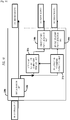
- Fig. 4 is a block diagram of an exemplary configuration of the first image processing unit 23a of Fig. 1 .
- the first image processing unit 23a includes a polarization parameter extraction unit 31a, a specular reflection component removing unit 32a, an image division unit 33a, a first feature point detection unit 34a, and a second feature point detection unit 35a.
- the polarization parameter extraction unit 31a extracts a polarization parameter indicating a polarization state of light on the surface of the object to be inspected, so as to supply the polarization parameter to the specular reflection component removing unit 32a and the second feature point detection unit 35a, on the basis of the input image data supplied from the detection device 12.
- the polarization parameter includes a polarization level indicating the degree of polarization when the light reflects from the surface of the object to be inspected and a normal vector indicating the angle of a normal of the surface of the object to be inspected with respect to the detection device 12.
- the detection device 12 detects the light in a polarization direction every 45° with four pixels adjacent to each other.
- the polarization parameter extraction unit 31a can extract the polarization parameter on the surface of the object to be inspected, detected through the four pixels, on the basis of polarization information acquired from the pixel values of the four pixels (the difference between the pixel values in response to the different polarization directions of the respective pixels).
- the specular reflection component removing unit 32a removes a specular reflection component being a component including the light specularly reflecting from the surface of the object to be inspected, from the input image data supplied from the detection device 12, on the basis of the polarization parameter supplied from the polarization parameter extraction unit 31a.
- the light reflecting from the surface of the object to be inspected typically includes a polarized specular reflection component and a non-polarized diffuse reflection component.
- the specular reflection component removing unit 32a can remove the specular reflection component, for example, with a method of independent component analysis (ICA), on the basis of an assumption that the diffuse reflection component and the specular reflection component are statistically independent. Then, the specular reflection component removing unit 32a acquires an image excluding the influence of the specular reflection component from an image acquired by the detection device 12, so as to supply image data thereof to the image division unit 33a.
- ICA independent component analysis
- the image division unit 33a divides the image data supplied from the specular reflection component removing unit 32a, in accordance with the detection areas of the wavelength bands detected by the detection device 12, so as to supply divided image data for each wavelength band to the first feature point detection unit 34a and the stitching processing unit 24 ( Fig. 1 ).
- the first feature point detection unit 34a detects a feature point indicating a distinctive point of a subject captured in the image based on the divided image data, so as to supply coordinate data indicating the coordinates of the feature point, to the stitching processing unit 24. For example, an edge of a point having a large variation in brightness or in color on the image, can be used as the feature point.
- the second feature point detection unit 35a detects a feature point indicating a distinctive point of a subject captured in the image including the polarization parameter supplied from the polarization parameter extraction unit 31a, mapped, so as to supply coordinate data indicating the coordinates of the feature point to the stitching processing unit 24.
- the first image processing unit 23a has the configuration, and can supply the divided image data that includes the specular reflection component removed and has been divided for each wavelength band, the coordinate data indicating the coordinates of the feature point acquired from the divided image for each wavelength band, and the coordinate data indicating the coordinates of the feature point on the image acquired on the basis of the polarization parameter, to the stitching processing unit 24.
- Fig. 5 is a block diagram of an exemplary configuration of the second image processing unit 23b of Fig. 1 .
- the second image processing unit 23b includes a polarization parameter extraction unit 31b, a specular reflection component removing unit 32b, an image division unit 33b, a first feature point detection unit 34b, and a second feature point detection unit 35b, similarly to the first image processing unit 23a of Fig. 2 .
- the second image processing unit 23b has the sequence of performing the processing, different from that of the first image processing unit 23a of Fig. 2 .
- the detection device 12 supplies the input image data to the image division unit 33b and then the image division unit 33b divides the image data in accordance with the detection areas of the wavelength bands in the detection device 12, in the second image processing unit 23b. Then, the image division unit 33b supplies divided image data for each wavelength band, to the polarization parameter extraction unit 31b and the specular reflection component removing unit 32b. Therefore, the polarization parameter extraction unit 31b extracts a polarization parameter from the divided image data divided for each wavelength band, and the specular reflection component removing unit 32b removes a specular reflection component from the divided image data divided for each wavelength band, in the second image processing unit 23b. After that, the first feature point detection unit 34b and the second feature point detection unit 35b each extract a feature point similar to those described above, so as to supply coordinate data indicating the feature point to the stitching processing unit 24.
- the second image processing unit 23b having the configuration in this manner, can supply the divided image data that has been divided for each wavelength band and includes the specular reflection component removed, the coordinate data indicating the coordinates of the feature point acquired from a divided image for each wavelength band, and the coordinate data indicating the coordinates of the feature point on the image acquired on the basis of the polarization parameter, to the stitching processing unit 24.
- the stitching processing unit 24 can stitch each divided image on the basis of the coordinate data indicating the coordinates of the feature point acquired from the divided image for each wavelength band and the coordinate data indicating the coordinates of the feature point on the image acquired on the basis of the polarization parameter, in the signal processing device 13. In this manner, the stitching processing unit 24 can improve the accuracy of stitching using a larger number of feature points.
- the polarization parameter is typically independent of the color of an object so that the stitching processing unit 24 can use, for positioning, a feature point based on the polarization parameter in the entire size of the detection device 12, receiving no influence of a chromatic filter. Accordingly, the stitching processing unit 24 can perform the stitching with higher precision.
- Fig. 6 is a flow chart for describing processing of an image having a wide range and high resolution in the vegetation inspection device 11.
- the processing starts and the vegetation inspection device 11 moves in the moving direction as illustrated in Fig. 2 .
- the detection device 12 acquires one image captured by one time of exposure so as to supply input image data of the image to the signal processing device 13.
- the image data analysis unit 21 of the signal processing device 13 performs analysis to an input image supplied from the detection device 12 at step S11 so as to supply an analysis result thereof to the image processing selection unit 22.
- the image processing selection unit 22 determines which of the image processing in the first image processing unit 23a and the image processing in the second image processing unit 23b is performed as image processing to the input image, in accordance with the analysis result supplied from the image data analysis unit 21 at step S12.
- step S13 in a case where the image processing selection unit 22 determines that the image processing in the first image processing unit 23a is performed to the input image, the image processing selection unit 22 supplies the input image to the first image processing unit 23a and then the processing proceeds to step S14.
- the polarization parameter extraction unit 31a of the first image processing unit 23a extracts a polarization parameter on the basis of the pixel values of four pixels having a different polarization direction, the four pixels being adjacent to each other in the image acquired by the detection device 12.
- the specular reflection component removing unit 32a removes a specular reflection component from the image acquired by the detection device 12, on the basis of the polarization parameter extracted by the polarization parameter extraction unit 31a at step S14.
- the image division unit 33a divides the image including the specular reflection component removed by the specular reflection component removing unit 32a at step S15, for each wavelength band detected by the detection device 12. Then, the image division unit 33a supplies a divided image for each wavelength band, to the first feature point detection unit 34a and the stitching processing unit 24.
- the first feature point detection unit 34a detects a feature point indicating a distinctive point on a subject captured in each divided image supplied from the image division unit 33a at step S16. Then, the first feature point detection unit 34a supplies coordinate data indicating the coordinates of the feature point detected from each divided image, to the stitching processing unit 24.
- the second feature point detection unit 35a detects a feature point indicating a distinctive point of a subject captured in the image including the polarization parameter mapped on the basis of the polarization parameter supplied from the polarization parameter extraction unit 31a. Then, the second feature point detection unit 35a supplies coordinate data indicating the coordinates of the feature point detected on the basis of the polarization parameter, for the entire image acquired by the detection device 12, to the stitching processing unit 24.
- the stitching processing unit 24 stitches each divided image supplied from the image division unit 33a at step S16, on the basis of the pieces of coordinate data supplied at steps S17 and S18.
- step S13 in a case where the image processing selection unit 22 determines that the image processing in the second image processing unit 23b is performed to the input image, the image processing selection unit 22 supplies the input image to the second image processing unit 23b so that the processing proceeds to step S20.
- the image division unit 33b of the second image processing unit 23b divides the image acquired by the detection device 12, for each wavelength band detected by the detection device 12. Then, the image division unit 33b supplies a divided image for each wavelength band, to the polarization parameter extraction unit 31b and the specular reflection component removing unit 32b.
- the polarization parameter extraction unit 31b extracts a polarization parameter for each divided image divided by the image division unit 33b, on the basis of the pixels values of four pixels having a different polarization direction, the four pixels being adjacent to each other.
- the specular reflection component removing unit 32b removes a specular reflection component from each divided image divided by the image division unit 33b on the basis of the polarization parameter extracted by the polarization parameter extraction unit 31b at step S21. Then, the specular reflection component removing unit 32b supplies the divided images including the specular reflection component removed, to the first feature point detection unit 34b and the stitching processing unit 24.
- the first feature point detection unit 34b detects a feature point indicating a distinctive point of a subject captured in each divided image supplied from the specular reflection component removing unit 32b at step S22. Then, the first feature point detection unit 34b supplies coordinate data indicating the coordinates of the feature point detected from each divided image, to the stitching processing unit 24.
- the second feature point detection unit 35b detects a feature point indicating a distinctive point of a subject captured in the image including the polarization parameter mapped on the basis of the polarization parameter supplied from the polarization parameter extraction unit 31b. Then, the second feature point detection unit 35b supplies coordinate data indicating the coordinates of the feature point detected on the basis of the polarization parameter, for the entire image acquired by the detection device 12, to the stitching processing unit 24.
- step S19 the processing proceeds to step S19, and, in this case, the stitching processing unit 24 stitches each divided image supplied from the image division unit 33a at step S20, on the basis of the feature point indicated with each of the pieces of coordinate data supplied at steps S23 and S24.
- the processing proceeds to step S25 and then the detection device 12 determines whether a necessary image has been acquired over the entire range of the object to be inspected. For example, the detection device 12 can determine that the necessary image has been acquired, when the processing is performed from the starting point from which the inspection of the object to be inspected is performed and the vegetation inspection device 11 arrives at an end point.
- step S25 in a case where the detection device 12 determines that the necessary image has not been acquired, namely, in a case where the vegetation inspection device 11 has not arrived at the end point, the processing goes back to step S11 and then similar processing is repeatedly performed.
- step S25 in a case where the detection device 12 determines that the necessary image has been acquired, namely, in a case where the vegetation inspection device 11 has arrived at the end point, the processing proceeds to step S26.
- the stitching processing unit 24 has generated an image having a wide range and high resolution over the entire range of the object to be inspected, and, at step S26, the signal processing device 13 outputs, as an output image, an image produced by the stitching processing unit 24 so that the processing is completed.
- the vegetation inspection device 11 can acquire an image captured with a wide range and high resolution for each wavelength band that can be detected by the detection device 12, over the entire range of the object to be inspected.
- the exemplary arrangement illustrated in Fig. 2 above is schematically illustrated in order to easily describe the pixel arrangement in the detection device 12, and the detection device 12 includes several millions or several tens of millions of fine pixels arranged on the light-receiving surface, in practice.
- the detection device 12 includes the pixels arranged to divide the light-receiving surface into four sections on the basis of the detection area for each wavelength band, as illustrated in Fig. 2 .
- the pixel arrangement in the detection device 12 is not limited to the example illustrated in Fig. 2 .
- the pixel arrangement in the detection device 12 will be described with reference to Figs. 7 to 12 .
- Fig. 7 is a view for describing an arrangement regulation of a minimum detection area of the pixels in the detection device 12.
- the detection device 12 includes a minimum detection area including 16 pixels integrally arranged to detect light in the same wavelength band, the 16 pixels including four arranged in the row direction and four arranged in the column direction.
- the detection device 12 includes four pixels including a polarization direction set every 45°, arranged to be adjacent to each other in a 2 ⁇ 2 matrix form, and the minimum detection area includes 16 pixels including sets of the four pixels, arranged in a 2 ⁇ 2 matrix form.
- the detection device 12 includes a red minimum detection area R, a green minimum detection area G, a blue minimum detection area B, and a near-infrared minimum detection area IR, arranged in the moving direction in which the detection device 12 relatively moves to the object to be inspected (in the row direction of Fig. 7 ). That is, when the red minimum detection area R, the green minimum detection area G, the blue minimum detection area B, and the near-infrared minimum detection area IR are viewed in the moving direction of the detection device 12, the arrangement regulation including the respective areas certainly arranged is provided. Accordingly, for example, when one-line scanning is performed to the object to be inspected, the detection device 12 can acquire divided images of the object to be inspected for the one line, in all the wavelength bands.
- the detection device 12 includes each minimum detection area having a size double to a pattern cycle of the polarization filters (2 ⁇ 2) in the row direction and in the column direction, set. Each minimum detection area is set in this manner, and the detection device 12 consecutively acquires, for example, an image to be superimposed by the width of at least two pixels, relatively moving to the object to be inspected. Accordingly, the signal processing device 13 can stitch each divided image with the stitching processing unit 24, and then can output an output image having a wide range and high resolution for each wavelength band that can be detected in the detection device 12.
- Fig. 8 is a view of an exemplary pixel arrangement of the minimum detection areas according to a different arrangement regulation.
- the detection device 12 can arrange the red minimum detection area R, the green minimum detection area G, the blue minimum detection area B, and the near-infrared minimum detection area IR, in accordance with an arrangement regulation including a 2 ⁇ 2 matrix.
- the detection device 12 including the minimum detection areas arranged in this manner is adopted and the vegetation inspection device 11 moves so that the respective minimum detection areas sequentially scan the object to be inspected.
- an output image having a wide range and high resolution can be output for each wavelength band that can be detected in the detection device 12.
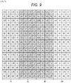
- Fig. 9 is a view of a first modification of the pixel arrangement.
- the detection device 12 includes the red detection area R, the green detection area G, the blue detection area B, and the near-infrared detection area IR, arranged to be long and rectangular in the column direction in comparison to the pixel arrangement illustrated in Fig. 2 .
- Fig. 10 is a view of a second modification of the pixel arrangement.
- the detection device 12 includes pixels arranged to have an arrangement regulation including the red detection area R, the green detection area G, the blue detection area B, and the near-infrared detection area IR certainly arranged when viewed in the row direction and in the column direction. That is, the exemplary pixel arrangement illustrated in Fig. 10 includes the detection areas of all the wavelength bands arranged for 16 detection areas arranged in a 4 ⁇ 4 matrix when viewed in the row direction and in the column direction.
- the exemplary pixel arrangement illustrated in Fig. 10 schematically illustrates an arrangement of the detection area of each wavelength band.
- One detection area corresponds to a minimum detection area described with reference to Fig. 7 , but each detection area may have a large size.
- the entire light-receiving surface of the detection device 12 may be divided into 16 detection areas.
- detection areas including a larger number of pixels arranged can be arranged repeatedly in a pattern illustrated in Fig. 10 .
- Fig. 11 is a view of a third modification of the pixel arrangement.
- the detection device 12 can arrange, for example, a detection area including pixels that detect non-polarized light in all the wavelength bands, in addition to the red detection area R, the green detection area G, the blue detection area B, and the near-infrared detection area IR. That is, the detection device 12 may include a detection area including no polarization filter and no color filter. On the basis of the pixel values of the pixels arranged in the detection area, the signal processing device 13 can acquire a white (monochrome) image due to light in any polarization directions.
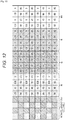
- Fig. 12 is a view of a fourth modification of the pixel arrangement.
- the detection device 12 can arrange, for example, a detection area including pixels that detect non-polarized light including three primary colors, in addition to the red detection area R, the green detection area G, the blue detection area B, and the near-infrared detection area IR. That is, the detection device 12 may include a detection area including no polarization filter but three-primary-color color filters arranged in a Bayer array for the pixels. On the basis of the pixel values of the pixels arranged in the detection area, the signal processing device 13 can acquire a color image due to light in any polarization directions.
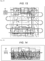
- the vegetation inspection device 11 is mounted on an unmanned aerial vehicle (UAV) 51, and can perform inspection to an object to be inspected, moving with the unmanned aerial vehicle 51.
- UAV unmanned aerial vehicle
- the vegetation inspection device 11 including the detection device 12 facing downward is fixed to the unmanned aerial vehicle 51, and, for example, acquiring an output image including a crop in a field just under the sky, captured in a wide range in plan view, is illustrated as exemplary utilization.
- the vegetation inspection device 11 including the detection device 12 facing horizontally is fixed to the unmanned aerial vehicle 51, and, for example, acquiring an output image including the raising state of the crop in height captured in a wide range with the unmanned aerial vehicle 51 moving along a farm road, is illustrated as exemplary utilization.
- rectangles indicated with a solid line represent a plurality of images acquired by one time of exposure in the detection device 12 and a rectangle indicated with a broken line represents an output image produced by stitching the images, in Figs. 13 and 14 .
- an outline arrow represents a moving route of the unmanned aerial vehicle 51.
- the vegetation inspection device 11 consecutively acquires a plurality of images while the unmanned aerial vehicle 51 including the vegetation inspection device 11 mounted, is moving, so that the vegetation inspection device 11 can acquire one output image including the object to be inspected captured with a wide range and high resolution. Therefore, the vegetation of the crop in a wide range, such as the field, can be inspected in detail with the output image.
- the vegetation inspection device 11 can acquire information on a sensor included in the unmanned aerial vehicle 51
- the vegetation inspection device 11 performs stitching with the stitching processing unit 24 on the basis of information on the location and the position of the unmanned aerial vehicle 51 so that an output image that has been stitched with high precision can be acquired.
- the vegetation inspection device 11 can appropriately select a size of the inspection area of each wavelength band in response to the size of the detection device 12 and the moving speed of the vegetation inspection device 11.
- the vegetation inspection device 11 can appropriately select a necessary number of wavelength bands in response to the purpose of inspection with the vegetation inspection device 11, for the number of wavelength bands (namely, the color number of chromatic filters) detected by the detection device 12.
- a degree of blur is estimated to occur in the moving distance and the moving direction of the unmanned aerial vehicle 51 for the purpose of inspecting the entire wide field with the unmanned aerial vehicle 51 as described above with reference to Figs. 13 and 14 .
- the size of each detection area is preferably made to be large (including a larger number of pixels) in order to securely stitch divided images.
- the size of each detection area may be made to be small for the purpose of performing inspection with the vegetation inspection device 11 minutely moving, such as for the purpose of detecting a small blemish of a small precision component.
- the present technology can be applied to, for example, a vegetation inspection system coupled through a network in addition to being included in a single-body device, such as the vegetation inspection device 11.
- the detection device 12 and the signal processing device 13 are coupled through the network so that an output image output from the signal processing device 13 can be transmitted to a display device or an analysis device through the network. Accordingly, inspection can be performed to a number of fields at remote locations as objects to be inspected, from any locations.
- each piece of processing described with reference to the flow chart above is not necessarily performed in a time series in accordance with the sequence described as a flow chart, and processing performed in parallel or individually (e.g., parallel processing or processing with an object) is also included.
- a program may be performed with processing by one CPU or may be performed with distributed processing by a plurality of CPUs.
- a system means the entire device including a plurality of devices in the present specification.
- the above processing in series can be performed by hardware or can be performed by software.
- a program included in the software is installed, from a program recording medium recording the program, into a computer built in dedicated hardware or a general purpose personal computer capable of performing various functions, for example, by installing various programs.
- Fig. 15 is a block diagram of an exemplary configuration of hardware of a computer that performs the above processing in series with a program.
- a central processing unit (CPU) 101, a read only memory (ROM) 102, and a random access memory (RAM) 103 are mutually coupled through a bus 104 in the computer.
- An input/output interface 105 is further coupled to the bus 104.
- An input unit 106 including a keyboard, a mouse, and a microphone, an output unit 107 including a display and a speaker, a storage unit 108 including a hard disk and a nonvolatile memory, a communication unit 109 including a network interface, and a drive 110 that drives a removable medium 111, such as a magnetic disk, an optical disc, a magneto-optical disc, or a semiconductor memory, are coupled to the input/output interface 105.
- the CPU 101 loads, for example, the program stored in the storage unit 108 into the RAM 103 so as to execute the program through the input/output interface 105 and the bus 104 so that the above processing in series is performed.
- the program executed by the computer is recorded in the removable medium 111 being a package medium including, for example, the magnetic disk (a flexible disk included), the optical disc (e.g., a compact disc-read only memory (CD-ROM) or a digital versatile disc (DVD)), the magneto-optical disc, or the semiconductor memory, so as to be provided or the program is provided through a transmission medium of wired communication or radio communication, such as a local area network, the Internet, or digital satellite broadcasting.
- the magnetic disk a flexible disk included
- the optical disc e.g., a compact disc-read only memory (CD-ROM) or a digital versatile disc (DVD)
- CD-ROM compact disc-read only memory
- DVD digital versatile disc
- the magneto-optical disc or the semiconductor memory
- the removable medium 111 is put into the drive 110 so that the program can be installed into the storage unit 108 through the input/output interface 105.
- the communication unit 109 receives the program through the transmission medium of the wired communication or the radio communication so that the program can be installed into the storage unit 108. Additionally, the program can be previously installed into the ROM 102 and the storage unit 108.
- Fig. 16 is another view for describing processing of producing an output image having a wide range.
- pluralities of images (each plurality having four image sets of four images for a total of sixteen images in the example of Fig. 16 ) computed from image data that is captured in a time series, the image data being acquired by the detection device 12, are illustrated in descending order at a left end of Fig. 16 .
- the detection device 12 can sequentially capture a plurality of image data.
- Each of the image sets captured at a particular exposure includes information for different polarization angles for each of the wavelength strips.
- a first exposure is performed to capture part of an object to be inspected, as the vegetation inspection device 11 is moved along the moving direction of FIG. 2 .
- a first image set has four images, shown as stacked images on the top left end of FIG. 16 , represent the image data captured at the first exposure.
- the four images of the first image set corresponds to four polarization angles of 0°, 45°, 90°, and 135° and is computed by the signal processing device 12, based on the image data acquired from the first exposure.
- a second exposure is performed to capture another part of the object to be inspected.
- a second image set with four other images stacked one over the other, shown below the first image set and slightly shifted to the right in FIG. 16 represent the image data captured at the second exposure.
- the four images of the second image set corresponds to four polarization angles of 0°, 45°, 90°, and 135° and is computed by the signal processing device 12, based on the image data acquired from the second exposure.
- the vegetation inspection device 12 is further moved along the moving direction and third and fourth image sets, each with four images, are shown in the left end of FIG. 16 .
- the signal processing device 13 divides the image data supplied from the detection device 12 into pluralities of divided images based on the wavelength band and the polarization angle.
- the stitching processing unit 24 sequentially stitches each plurality of the pluralities of divided images in the same wavelength band together. For example, based on the red wavelength band and the polarization angle of zero degrees, a red divided image R1 is divided from the first image set of the first plurality of images, a red divided image R2 is divided from the first image set of the second plurality of images, a red divided image R3 is divided from the first image set of the third plurality of images, and a red divided image R4 is divided from the first image set of the fourth plurality of images, are sequentially stitched by the stitching processing unit 24.
- the stitching processing unit 24 stitches red divided images divided from the second image sets (polarization angle of forty-five degrees), the third image sets (polarization angle of ninety degrees), and the fourth image sets (polarization angle of one-hundred and thirty-five degrees) of the pluralities of images. Note that, the stitching processing unit 24 stitches divided images with the same polarization angle in the other wavelength bands, for each wavelength band.
- the signal processing device 13 can acquire a plurality of output red images R (polarization angles of 0°, 45°, 90°, and 135°) including the red divided images stitched with a wide range and high resolution, a plurality of output green images G (polarization angles of 0°, 45°, 90°, and 135°) including the green divided images stitched with a wide range and high resolution, a plurality of output blue images B (polarization angles of 0°, 45°, 90°, and 135°) including the blue divided images stitched with a wide range and high resolution, and a plurality of output near-infrared images IR (polarization angles of 0°, 45°, 90°, and 135°) including the near-infrared divided images stitched with a wide range and high resolution.
- R polarization angles of 0°, 45°, 90°, and 135°
- a plurality of output green images G polarization angles of 0°, 45°, 90°, and 135
- the signal processing device 13 may use the plurality of output red images R (polarization angles of 0°, 45°, 90°, and 135°) and a polarization fitting process to generate a single output red image at any polarization angle.
- the signal processing device 13 may use the plurality of output green images G (polarization angles of 0°, 45°, 90°, and 135°) and the polarization fitting process to generate a single output green image at any polarization angle.
- the signal processing device 13 may use the plurality of output blue images B (polarization angles of 0°, 45°, 90°, and 135°) and the polarization fitting process to generate a single output blue image at any polarization angle.
- the signal processing device 13 may use the plurality of output near-infrared images IR (polarization angles of 0°, 45°, 90°, and 135°) and the polarization fitting process to generate a single output near-infrared image at any polarization angle.
- the signal processing device 13 may select one of the plurality of output red images R (polarization angles of 0°, 45°, 90°, and 135°) as a single output red image at a pre-determined polarization angle (for example, 0°, 45°, 90°, or 135°).
- the signal processing device 13 may select one of the plurality of output green images G (polarization angles of 0°, 45°, 90°, and 135°) as a single output green image at a pre-determined polarization angle (for example, 0°, 45°, 90°, or 135°).
- the signal processing device 13 may select one of the plurality of output blue images B (polarization angles of 0°, 45°, 90°, and 135°) as a single output blue image at a pre-determined polarization angle (for example, 0°, 45°, 90°, or 135°).
- the signal processing device 13 may select one of the plurality of output near-infrared images IR (polarization angles of 0°, 45°, 90°, and 135°) as a single output near-infrared image at a pre-determined polarization angle (for example, 0°, 45°, 90°, or 135°).
- the signal processing device 13 may output image data included in the single output red image, the single output green image, the single output blue image, and the single output near-infrared image, as output image data in an integrated format (color image data + near-infrared image data), as illustrated at a right end of Fig. 16 .
- the vegetation inspection device 11 has the configuration, and can acquire an output image having a wide range and high resolution for each predetermined wavelength band at any polarization angle.
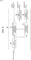
- Fig. 17 is a block diagram of another exemplary configuration of the first image processing unit 23a of Fig. 1 .
- the first image processing unit 23a includes a polarization parameter extraction unit 31a, a specular reflection component removing unit 32a, a first image division unit 33a, a first feature point detection unit 34a, a second feature point detection unit 35a, and a second image division unit 36a.
- the polarization parameter extraction unit 31a extracts a polarization parameter indicating a polarization state of light on the surface of the object to be inspected, so as to supply the polarization parameter to the specular reflection component removing unit 32a and the second feature point detection unit 35a, on the basis of the input image data supplied from the detection device 12.
- the polarization parameter includes a polarization level indicating the degree of polarization when the light reflects from the surface of the object to be inspected and a normal vector indicating the angle of a normal of the surface of the object to be inspected with respect to the detection device 12.
- the detection device 12 detects the light in a polarization direction every 45° with four pixels adjacent to each other.
- the polarization parameter extraction unit 31a can extract the polarization parameter on the surface of the object to be inspected, detected through the four pixels, on the basis of polarization information acquired from the pixel values of the four pixels (the difference between the pixel values in response to the different polarization directions of the respective pixels).
- the specular reflection component removing unit 32a removes a specular reflection component being a component including the light specularly reflecting from the surface of the object to be inspected, from the input image data supplied from the detection device 12, on the basis of the polarization parameter supplied from the polarization parameter extraction unit 31a.
- the light reflecting from the surface of the object to be inspected typically includes a polarized specular reflection component and a non-polarized diffuse reflection component.
- the specular reflection component removing unit 32a can remove the specular reflection component, for example, with a method of independent component analysis (ICA), on the basis of an assumption that the diffuse reflection component and the specular reflection component are statistically independent. Then, the specular reflection component removing unit 32a acquires an image excluding the influence of the specular reflection component from an image acquired by the detection device 12, so as to supply image data thereof to the first image division unit 33a.
- ICA independent component analysis
- the first image division unit 33a divides the image data supplied from the specular reflection component removing unit 32a, in accordance with the detection areas of the wavelength bands detected by the detection device 12, so as to supply divided image data for each wavelength band to the first feature point detection unit 34a.
- the first feature point detection unit 34a detects a feature point indicating a distinctive point of a subject captured in the image based on the divided image data from the first image division unit 33a, so as to supply coordinate data indicating the coordinates of the feature point, to the stitching processing unit 24.
- a feature point indicating a distinctive point of a subject captured in the image based on the divided image data from the first image division unit 33a, so as to supply coordinate data indicating the coordinates of the feature point, to the stitching processing unit 24.
- the second feature point detection unit 35a detects a feature point indicating a distinctive point of a subject captured in the image including the polarization parameter supplied from the polarization parameter extraction unit 31a, mapped, so as to supply coordinate data indicating the coordinates of the feature point to the stitching processing unit 24.
- the second image division unit 36a divides the input image data supplied from the detection device 12, in accordance with the polarization angle associated with each pixel of the detection device 12, so as to supply divided image data for each polarization angle to the stitching processing unit 24 ( Fig. 1 ).
- the first image processing unit 23a has the configuration, and can supply the divided image data based on polarization angles of the pixels of the detection device 12, and the divided image data includes the specular reflection component to the stitching processing unit 24.
- the first image processing unit 23 has the configuration, and can supply the coordinate data indicating the coordinates of the feature point acquired from the divided image data that includes the specular reflection component removed and has been divided for each wavelength band, and the coordinate data indicating the coordinates of the feature point on the image acquired on the basis of the polarization parameter, to the stitching processing unit 24.
- the stitching processing unit 24 may use one or both of the coordinate data from the first feature point detection unit 34a and the second feature point detection unit 35a.
- the polarization angle of the divided image data to be stitched by the stitching processing unit 24 may be specified by a user or selected by the stitching processing unit 24 based on a result of image analysis.
- the specular reflection component determined by the specular reflection component removal unit 32a may be used by the stitching processing unit 24 to select a polarization angle with the lowest reflection component.
- the stitching processing unit 24 may use the divided image data (for example, color image data + near-infrared image data) with a polarization fitting process to generate a single output image at any polarization angle.
- Fig. 18 is a block diagram of another exemplary configuration of the second image processing unit 23b of Fig. 1 .
- the second image processing unit 23b includes a polarization parameter extraction unit 31b, a specular reflection component removing unit 32b, an image division unit 33b, a first feature point detection unit 34b, and a second feature point detection unit 35b, similarly to the first image processing unit 23a of Fig. 17 .
- the second image processing unit 23b has the sequence of performing the processing, different from that of the first image processing unit 23a of Fig. 17 .
- the detection device 12 supplies the input image data to the image division unit 33b.
- the image division unit 33b divides the input image data supplied from the detection device 12, in accordance with the polarization angle associated with each pixel of the detection device 12, so as to supply divided image data for each polarization angle to the stitching processing unit 24 ( Fig. 1 ).
- the image division unit 33b further divides the divided image data corresponding to each of the polarized angles, in accordance with the detection areas of the wavelength bands in the detection device 12, in the second image processing unit 23b. Then, the image division unit 33b supplies divided image data for each wavelength band, to the polarization parameter extraction unit 31b and the specular reflection component removing unit 32b.
- the polarization parameter extraction unit 31b extracts a polarization parameter from the divided image data divided for each wavelength band, and the specular reflection component removing unit 32b removes a specular reflection component from the divided image data divided for each wavelength band, in the second image processing unit 23b.
- the first feature point detection unit 34b and the second feature point detection unit 35b each extract a feature point similar to those described above, so as to supply coordinate data indicating the feature point to the stitching processing unit 24.
- the second image processing unit 23b having the configuration in this manner, can supply the divided image data based on polarization angles of the pixels of the detection device 12, and the divided image data includes the specular reflection component to the stitching processing unit 24.
- the second image processing unit 23b can also supply the coordinate data indicating the coordinates of the feature point acquired from a divided image for each wavelength band, and the coordinate data indicating the coordinates of the feature point on the image acquired on the basis of the polarization parameter, to the stitching processing unit 24.
- the stitching processing unit 24 may use one or both of the coordinate data from the first feature point detection unit 34b and the second feature point detection unit 35b.
- the polarization angle of the divided image data to be stitched by the stitching processing unit 24 may be specified by a user or selected by the stitching processing unit 24 based on a result of image analysis.
- the specular reflection component determined by the specular reflection component removal unit 32b may be used by the stitching processing unit 24 to select a polarization angle with the lowest reflection component.
- the stitching processing unit 24 may use the divided image data (for example, color image data + near-infrared image data) with a polarization fitting process to generate a single output image at any polarization angle.
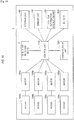
- Fig. 19 is a block diagram of an exemplary embodiment of the unmanned aerial vehicle 51 of Figs. 13 and 14 .
- the unmanned aerial vehicle 51 is configured to include a vegetation inspection device 11, rotors 104a to 104d, motors 108a to 108d, a control unit 110, a communication unit 120, a sensor unit 130, a position information acquisition unit 132, a storage unit 140, and a battery 150.
- the control unit 110 controls an operation of the unmanned aerial vehicle 51.
- the control unit 110 can control an adjustment of the rotational speed of the rotors 104a to 104d by an adjustment of the rotational speed of the motors 108a to 108d, the imaging process by the vegetation inspection device 11, the transmission and reception processes of information to/from other devices (for example, a control terminal) through the communication unit 120, and storage and reading of information in and from the storage unit 140.
- the control unit 110 controls a flight in which the rotational speed of the motors 108a to 108d is adjusted and execution of the imaging process of the still image by the imaging device 101 based on the flight information transmitted from the control terminal 200.
- the control unit 110 controls the motors 108a to 108d or the vegetation inspection device 11 based on the flight information transmitted from the control terminal.
- the control unit 110 can control the detection device 12 to consecutively capture one or more images, and provide the one or more images to the control terminal based on a request of the control terminal.
- the control unit 110 can control the stitching processing unit 24 to stitch the captured images to provide an output image to the control terminal based on another request of the control terminal.
- the rotors 104a to 104d cause the unmanned aerial vehicle 51 to fly by generating a lift force from rotation thereof. Rotation of the rotors 104a to 104d is caused by rotation of the motors 108a to 108d.
- the motors 108a to 108d cause the rotors 104a to 104d to rotate. The rotation of the motors 108a to 108d can be controlled by the control unit 110.
- the communication unit 120 performs transmission and reception processes of information to/from the control terminal through wireless communication.
- the unmanned aerial vehicle 51 transmits image data captured by the vegetation inspection device 11 from the communication unit 120 to the control terminal.
- the image data is one or more divided images.
- the image data is one image, for example, a raw polarized image of one wavelength band.
- the image data is an output image (a stitched image).
- the unmanned aerial vehicle 51 receives instructions relating to flight from the control terminal using the communication unit 120.
- the sensor unit 130 is a group of devices that acquire a state of the unmanned aerial vehicle 51, and may include, for example, an acceleration sensor, a gyro sensor, an ultrasonic sensor, a pneumatic sensor, an optical flow sensor, a laser range finder, or other suitable sensor.
- the sensor unit 130 can convert an acquired state of the unmanned aerial vehicle 51 into a predetermined signal, and provide the signal to the control unit 110 when necessary.
- the position information acquisition unit 132 acquires information of a current position of the unmanned aerial vehicle 51 using, for example, the GPS, a vision sensor, or other suitable positioning unit.
- the position information acquisition unit 132 can provide the acquired information of the current position of the unmanned aerial vehicle 51 to the control unit 110 when necessary.
- the control unit 110 executes control of the flight of the unmanned aerial vehicle 51 based on the flight information received from the control terminal using the information of the current position of the unmanned aerial vehicle 51 acquired by the position information acquisition unit 132.
- the sensor unit 130 detects an obstacle that may interfere with a flight at the time of the flight. As the sensor unit 130 detects an obstacle, the unmanned aerial vehicle 51 can provide information related to the detected obstacle to the control terminal.
- the storage unit 140 stores a variety of information. Examples of the information stored in the storage unit 140 include the flight information of the unmanned aerial vehicle 51 transmitted from the control terminal, and image data from the vegetation inspection device 11.
- the image data is one or more divided images.
- the image data is one image, for example, a raw polarized image of one wavelength band.
- the image data is an output image (a stitched image).
- the battery 150 accumulates electric power for operating the unmanned aerial vehicle 51.
- the battery 150 may be a primary battery in which only discharging is possible or may be a secondary battery in which charging is also possible, but when the battery 150 is the secondary battery, for example, the battery 150 can be supplied with electric power from a charging station.
- the unmanned aerial vehicle 51 may have the configuration illustrated in FIG. 19 and thus can perform an automatic flight based on the flight path included in the flight information transmitted from the control terminal and execute the imaging processes described herein.
- the present technology may have several different applications other than as a vegetation inspection device. Indeed, the present technology is applicable to wide imaging ranges that require scanning and stitching of images. For example, one application of the present technology is factory automation when the object of interest requires more than one scan, and in particular, more than one robotic scan. Another application of the present technology is a microscope image analysis of mineral salts. Another application of the present technology is a measurement of stress strain (photo elasticity). Another application of the present technology is a fault detection of a transparent resin molded product. Another application of the present technology is detection of contaminants in glass. Yet another application of the present technology is a measurement of film thickness.
Landscapes
- Engineering & Computer Science (AREA)
- Multimedia (AREA)
- Signal Processing (AREA)
- Physics & Mathematics (AREA)
- Theoretical Computer Science (AREA)
- General Physics & Mathematics (AREA)
- Spectroscopy & Molecular Physics (AREA)
- Computer Vision & Pattern Recognition (AREA)
- Computing Systems (AREA)
- Investigating Or Analysing Materials By Optical Means (AREA)
- Image Processing (AREA)
- Investigating Materials By The Use Of Optical Means Adapted For Particular Applications (AREA)
- Studio Devices (AREA)
Claims (15)
- Dispositif de traitement (13) comprenant :un circuit (21, 22, 23a, 23b, 24) configuré pouracquérir une pluralité d'images capturées dans une série chronologique par un capteur d'image (12), chacune de la pluralité d'images étant basée sur la lumière dans une parmi une pluralité de directions de polarisation prédéterminées et dans une parmi une pluralité de bandes de longueur d'onde prédéterminées (R, G, B, IR) ;caractérisé en ce que ledit circuit est en outre configuré pourassembler au moins une partie de la pluralité d'images correspondant à une direction de polarisation unique et à une bande de longueur d'onde prédéterminée unique parmi la pluralité de bandes de longueur d'onde prédéterminées de façon à générer une image composite.
- Dispositif de traitement selon la revendication 1, le circuit étant en outre configuré pour
assembler la pluralité d'images de façon à générer une pluralité d'images composites comprenant l'image composite, chacune de la pluralité d'images composites correspondant à l'une de la pluralité de directions de polarisation prédéterminées et à l'une de la pluralité de bandes de longueur d'onde prédéterminées, et
générer une image de sortie finale à partir de la pluralité d'images composites. - Dispositif de traitement selon la revendication 1, le circuit étant en outre configuré pour
assembler la pluralité d'images de façon à générer une première pluralité d'images composites comprenant l'image composite, chacune de la première pluralité d'images composites correspondant à l'une de la pluralité de directions de polarisation prédéterminées et à l'une de la pluralité de bandes de longueur d'onde prédéterminées,
assembler la première pluralité d'images composites pour générer une seconde pluralité d'images composites, chacune de la seconde pluralité d'images composites correspondant à l'une de la pluralité de bandes de longueur d'onde prédéterminées, et
générer une image de sortie finale à partir de la seconde pluralité d'images composites. - Dispositif de traitement selon la revendication 1, comprenant en outre :un circuit d'extraction de paramètre de polarisation configuré pour extraire un paramètre de polarisation indiquant un état de polarisation de la lumière sur une surface d'un objet d'inspection à partir d'une ou plusieurs images de la pluralité d'images ; etun circuit d'élimination de composante de réflexion spéculaire configuré pour éliminer une composante de réflexion spéculaire sur la surface de l'objet d'inspection à partir de la ou des images de la pluralité d'images sur la base du paramètre de polarisation.
- Dispositif de traitement selon la revendication 4,
la pluralité d'images étant acquise à partir d'éléments capteurs qui sont agencés ensemble de manière adjacente,
un certain nombre d'éléments capteurs correspondant à un certain nombre de la pluralité de directions de polarisation prédéterminées, et
le circuit d'extraction de paramètre de polarisation étant en outre configuré pour extraire le paramètre de polarisation sur la base d'une différence de sortie entre les éléments capteurs. - Dispositif de traitement selon la revendication 4, comprenant en outre :un circuit de détection de point caractéristique de paramètre de polarisation configuré pour détecter un point caractéristique à partir de la ou des images de la pluralité d'images,pour assembler au moins la partie de la pluralité d'images correspondant à la direction de polarisation unique et à la bande de longueur d'onde prédéterminée unique parmi la pluralité de bandes de longueur d'onde prédéterminées de façon à générer l'image composite, le circuit étant en outre configuré pour assembler au moins la partie de la pluralité d'images sur la base du point caractéristique.
- Dispositif de traitement selon la revendication 6, comprenant en outre :
un circuit de division configuré pour diviser la pluralité d'images en des pluralités d'images divisées, chaque pluralité d'images divisées étant basée au moins en partie sur l'une de la pluralité de bandes de longueur d'onde prédéterminées. - Dispositif de traitement selon la revendication 7,
le circuit d'extraction de paramètre de polarisation étant en outre configuré pour commander le circuit de division afin de diviser la pluralité d'images en les pluralités d'images divisées en réponse à l'extraction du paramètre de polarisation. - Dispositif de traitement selon la revendication 7,
le circuit de division étant en outre configuré pour commander le circuit d'extraction de paramètre de polarisation afin d'extraire le paramètre de polarisation en réponse à la division de la pluralité d'images en les pluralités d'images divisées. - Dispositif de traitement selon la revendication 7, comprenant en outre :
un circuit d'analyse configuré pour analyser la pluralité d'images ; et un circuit de sélection de traitement configuré pour sélectionner entre un premier traitement de la pluralité d'images et un second traitement de la pluralité d'images sur la base d'un résultat d'analyse du circuit d'analyse. - Dispositif de traitement selon la revendication 10,
pour analyser la pluralité d'images, le circuit d'analyse étant configuré pour
acquérir un histogramme de valeurs de pixels comprises dans une image de la pluralité d'images qui est acquise,
déterminer un nombre de valeurs de pixels dans l'image qui sont plus petites qu'une valeur de référence spécifique,
déterminer si le nombre de valeurs de pixels dans l'image qui sont plus petites que la valeur de référence spécifique dépasse une valeur seuil,
en réponse à la détermination que le nombre de valeurs de pixels dépasse la valeur seuil, le circuit de sélection de traitement étant configuré pour sélectionner le premier traitement de la pluralité d'images, et
en réponse à la détermination que le nombre de valeurs de pixels ne dépasse pas la valeur seuil, le circuit de sélection de traitement étant configuré pour sélectionner le second traitement de la pluralité d'images. - Dispositif de traitement selon la revendication 10,
dans le premier traitement de la pluralité d'images, le circuit de division divisant la ou les images de la pluralité d'images en les pluralités d'images divisées. - Dispositif de traitement selon la revendication 10,
dans le second traitement de la pluralité d'images, le circuit d'élimination de composante de réflexion spéculaire éliminant la composante de réflexion spéculaire de la ou des images de la pluralité d'images sur la base du paramètre de polarisation extrait par le circuit d'extraction de paramètre de polarisation. - Procédé comprenant :l'acquisition, avec un circuit (21, 22, 23a, 23b, 24), d'une pluralité d'images capturées dans une série chronologique par un capteur d'image, chacune de la pluralité d'images étant basée sur une lumière dans une parmi une pluralité de directions de polarisation prédéterminées et dans une parmi une pluralité de bandes de longueur d'onde prédéterminées (R, G, B, IR) ;caractérisé en ce que ledit procédé comprend en outre :
l'assemblage, avec le circuit, d'au moins une partie de la pluralité d'images correspondant à une direction de polarisation unique et à une bande de longueur d'onde prédéterminée unique parmi la pluralité de bandes de longueur d'onde prédéterminées de façon à générer une image composite. - Support non transitoire lisible par ordinateur stockant un programme pour amener un processeur électronique (101) à exécuter un ensemble d'opérations, l'ensemble d'opérations comprenant :l'acquisition d'une pluralité d'images capturées dans une série chronologique par un capteur d'image (12), chacune de la pluralité d'images étant basée sur la lumière dans une d'une pluralité de directions de polarisation prédéterminées et dans une d'une pluralité de bandes de longueur d'onde prédéterminées (R, G, B, IR) ; etl'assemblage d'au moins une partie de la pluralité d'images correspondant à une direction de polarisation unique et à une bande de longueur d'onde prédéterminée unique parmi la pluralité de bandes de longueur d'onde prédéterminée pour générer une image composite.
Applications Claiming Priority (2)
| Application Number | Priority Date | Filing Date | Title |
|---|---|---|---|
| JP2016159853A JP6697680B2 (ja) | 2016-08-17 | 2016-08-17 | 信号処理装置、信号処理方法、およびプログラム |
| PCT/JP2017/028288 WO2018034165A1 (fr) | 2016-08-17 | 2017-08-03 | Dispositif de traitement de signal, procédé de traitement de signal et programme |
Publications (2)
| Publication Number | Publication Date |
|---|---|
| EP3491817A1 EP3491817A1 (fr) | 2019-06-05 |
| EP3491817B1 true EP3491817B1 (fr) | 2020-09-30 |
Family
ID=60953921
Family Applications (1)
| Application Number | Title | Priority Date | Filing Date |
|---|---|---|---|
| EP17826592.2A Not-in-force EP3491817B1 (fr) | 2016-08-17 | 2017-08-03 | Dispositif de traitement de signal, procédé de traitement de signal et programme |
Country Status (5)
| Country | Link |
|---|---|
| US (1) | US10776901B2 (fr) |
| EP (1) | EP3491817B1 (fr) |
| JP (1) | JP6697680B2 (fr) |
| CN (1) | CN109565545B (fr) |
| WO (1) | WO2018034165A1 (fr) |
Families Citing this family (10)
| Publication number | Priority date | Publication date | Assignee | Title |
|---|---|---|---|---|
| JP2017099616A (ja) * | 2015-12-01 | 2017-06-08 | ソニー株式会社 | 手術用制御装置、手術用制御方法、およびプログラム、並びに手術システム |
| JP6697681B2 (ja) * | 2016-08-17 | 2020-05-27 | ソニー株式会社 | 検査装置、検査方法、およびプログラム |
| JP2020162016A (ja) * | 2019-03-27 | 2020-10-01 | ソニー株式会社 | 状態検出装置、状態検出システム及び状態検出方法 |
| CN110087004B (zh) * | 2019-04-23 | 2021-07-13 | Oppo广东移动通信有限公司 | 一种单色偏振式cis及图像处理方法、存储介质 |
| TWI853102B (zh) * | 2019-10-07 | 2024-08-21 | 日商索尼半導體解決方案公司 | 電子機器 |
| CN110855897B (zh) * | 2019-12-20 | 2021-10-15 | 维沃移动通信有限公司 | 图像拍摄方法、装置、电子设备及存储介质 |
| JP7523940B2 (ja) | 2020-04-24 | 2024-07-29 | 株式会社Nttドコモ | 撮影装置および情報処理装置 |
| US11831858B2 (en) * | 2020-05-08 | 2023-11-28 | Shenzhen GOODIX Technology Co., Ltd. | Passive three-dimensional image sensing based on referential image blurring |
| DE102022201523A1 (de) * | 2021-09-10 | 2023-03-16 | Fraunhofer-Gesellschaft zur Förderung der angewandten Forschung eingetragener Verein | Ein Bildsensor, ein Verfahren zum Betreiben eines Bildsensors, ein Verfahren zum Herstellen eines Bildsensors und ein stationäres Gerät oder ein Fahrzeug oder eine Drohne mit einem Bildsensor |
| US20230370563A1 (en) * | 2022-05-11 | 2023-11-16 | The Boeing Company | Multi-spectral and panchromatic imaging apparatus and associated system and method |
Family Cites Families (16)
| Publication number | Priority date | Publication date | Assignee | Title |
|---|---|---|---|---|
| JPS4932978B1 (fr) | 1969-06-10 | 1974-09-04 | ||
| US5790188A (en) * | 1995-09-07 | 1998-08-04 | Flight Landata, Inc. | Computer controlled, 3-CCD camera, airborne, variable interference filter imaging spectrometer system |
| JP5259033B2 (ja) * | 2001-08-03 | 2013-08-07 | オリンパス株式会社 | 内視鏡システム |
| US7557918B1 (en) | 2006-04-05 | 2009-07-07 | Itt Manufacturing Enterprises, Inc. | Spectral polarimetric image detection and analysis methods and apparatus |
| EP3828519A3 (fr) * | 2007-05-31 | 2021-10-06 | Panasonic Intellectual Property Management Co., Ltd. | Dispositif de traitement d'images |
| AU2008289019B2 (en) * | 2007-08-17 | 2013-07-04 | Oral Cancer Prevention International Inc. | Feature dependent extended depth of focusing on semi-transparent biological specimens |
| US8463078B2 (en) * | 2007-08-23 | 2013-06-11 | Lockheed Martin Corporation | Multi-bank TDI approach for high-sensitivity scanners |
| JP2009139356A (ja) * | 2007-12-04 | 2009-06-25 | Photonic Lattice Inc | 偏光計測装置 |
| JP2010104422A (ja) * | 2008-10-28 | 2010-05-13 | Fujifilm Corp | 撮像システムおよび撮像方法 |
| WO2012017600A1 (fr) | 2010-08-04 | 2012-02-09 | パナソニック株式会社 | Elément imageur et dispositif d'imagerie |
| KR101087172B1 (ko) * | 2011-07-13 | 2011-11-28 | 동국대학교 경주캠퍼스 산학협력단 | 고온 금속 표면 3차원 형상 추출 시스템 및 방법 |
| JP6325738B2 (ja) | 2014-03-27 | 2018-05-16 | 華為技術有限公司Huawei Technologies Co.,Ltd. | 光性能パラメータを監視するための装置および方法、ならびに光送信システム |
| US9813601B2 (en) * | 2014-05-06 | 2017-11-07 | Urugus S.A. | Imaging device for scenes in apparent motion |
| US20160006954A1 (en) * | 2014-07-03 | 2016-01-07 | Snap Vision Technologies LLC | Multispectral Detection and Processing From a Moving Platform |
| JP6447121B2 (ja) * | 2014-12-26 | 2019-01-09 | 株式会社リコー | 画像処理装置、画像処理方法、撮像システム、画像処理システム、およびプログラム |
| CN105785395B (zh) | 2016-03-17 | 2018-03-09 | 四川知周科技有限责任公司 | 一种多波长光束合成的相干多普勒激光测风雷达 |
-
2016
- 2016-08-17 JP JP2016159853A patent/JP6697680B2/ja active Active
-
2017
- 2017-08-03 US US16/301,971 patent/US10776901B2/en not_active Expired - Fee Related
- 2017-08-03 CN CN201780048126.8A patent/CN109565545B/zh not_active Expired - Fee Related
- 2017-08-03 EP EP17826592.2A patent/EP3491817B1/fr not_active Not-in-force
- 2017-08-03 WO PCT/JP2017/028288 patent/WO2018034165A1/fr unknown
Non-Patent Citations (1)
| Title |
|---|
| None * |
Also Published As
| Publication number | Publication date |
|---|---|
| WO2018034165A1 (fr) | 2018-02-22 |
| CN109565545B (zh) | 2021-03-12 |
| US20190188827A1 (en) | 2019-06-20 |
| JP2018029250A (ja) | 2018-02-22 |
| JP6697680B2 (ja) | 2020-05-27 |
| EP3491817A1 (fr) | 2019-06-05 |
| US10776901B2 (en) | 2020-09-15 |
| CN109565545A (zh) | 2019-04-02 |
Similar Documents
| Publication | Publication Date | Title |
|---|---|---|
| EP3491817B1 (fr) | Dispositif de traitement de signal, procédé de traitement de signal et programme | |
| US10893221B2 (en) | Imaging sensor with wavelength detection regions and pre-determined polarization directions | |
| US10043290B2 (en) | Image processing to enhance distance calculation accuracy | |
| EP3113479B1 (fr) | Caméra à fonction plenoptique par fovéation | |
| US9843788B2 (en) | RGB-D imaging system and method using ultrasonic depth sensing | |
| US8774551B2 (en) | Image processing apparatus and image processing method for reducing noise | |
| CN102685511A (zh) | 图像处理设备和图像处理方法 | |
| EP3013047A1 (fr) | Pas de pixel multiples de super résolution | |
| US20180075615A1 (en) | Imaging device, subject information acquisition method, and computer program | |
| EP2635019B1 (fr) | Procédé et dispositif de traitement d'images et programme | |
| US20160344961A1 (en) | Image Sensors for Robust On Chip Phase Detection, and Associated System And Methods | |
| CN114173066A (zh) | 成像系统和方法 | |
| US20220103797A1 (en) | Integrated Spatial Phase Imaging | |
| WO2017162596A1 (fr) | Procédé de correction d'aberration affectant des données de champ lumineux | |
| EP3499178A1 (fr) | Système de traitement d'images, programme de traitement d'images et procédé de traitement d'images | |
| CN107529726B (zh) | 检查装置、检查方法和记录介质 | |
| JPWO2018212008A1 (ja) | 撮像装置及び画像合成装置 | |
| US10614275B2 (en) | Position specifying apparatus and position specifying method | |
| US20230061831A1 (en) | Estimation device and method | |
| KR20150009842A (ko) | 카메라 모듈용 결함 픽셀 평가 시스템 및 이를 사용한 카메라 모듈용 결함 픽셀 평가 방법 | |
| CN112866546B (zh) | 对焦方法和装置、电子设备、计算机可读存储介质 | |
| CN117710306B (zh) | 用于半导体器件缺陷的定位方法、处理器及存储介质 | |
| CN103891274A (zh) | 用于匹配自适应颜色滤波器的滤波器特性以及用于运行图像摄取装置的方法和设备 | |
| CN113228629A (zh) | 摄像装置 | |
| CN118317212A (zh) | 一种校正图像动态坏点的方法及装置 |
Legal Events
| Date | Code | Title | Description |
|---|---|---|---|
| STAA | Information on the status of an ep patent application or granted ep patent |
Free format text: STATUS: UNKNOWN |
|
| STAA | Information on the status of an ep patent application or granted ep patent |
Free format text: STATUS: THE INTERNATIONAL PUBLICATION HAS BEEN MADE |
|
| PUAI | Public reference made under article 153(3) epc to a published international application that has entered the european phase |
Free format text: ORIGINAL CODE: 0009012 |
|
| STAA | Information on the status of an ep patent application or granted ep patent |
Free format text: STATUS: REQUEST FOR EXAMINATION WAS MADE |
|
| 17P | Request for examination filed |
Effective date: 20190211 |
|
| AK | Designated contracting states |
Kind code of ref document: A1 Designated state(s): AL AT BE BG CH CY CZ DE DK EE ES FI FR GB GR HR HU IE IS IT LI LT LU LV MC MK MT NL NO PL PT RO RS SE SI SK SM TR |
|
| AX | Request for extension of the european patent |
Extension state: BA ME |
|
| DAV | Request for validation of the european patent (deleted) | ||
| DAX | Request for extension of the european patent (deleted) | ||
| GRAP | Despatch of communication of intention to grant a patent |
Free format text: ORIGINAL CODE: EPIDOSNIGR1 |
|
| STAA | Information on the status of an ep patent application or granted ep patent |
Free format text: STATUS: GRANT OF PATENT IS INTENDED |
|
| INTG | Intention to grant announced |
Effective date: 20200420 |
|
| GRAS | Grant fee paid |
Free format text: ORIGINAL CODE: EPIDOSNIGR3 |
|
| GRAA | (expected) grant |
Free format text: ORIGINAL CODE: 0009210 |
|
| STAA | Information on the status of an ep patent application or granted ep patent |
Free format text: STATUS: THE PATENT HAS BEEN GRANTED |
|
| AK | Designated contracting states |
Kind code of ref document: B1 Designated state(s): AL AT BE BG CH CY CZ DE DK EE ES FI FR GB GR HR HU IE IS IT LI LT LU LV MC MK MT NL NO PL PT RO RS SE SI SK SM TR |
|
| REG | Reference to a national code |
Ref country code: CH Ref legal event code: EP Ref country code: GB Ref legal event code: FG4D |
|
| REG | Reference to a national code |
Ref country code: AT Ref legal event code: REF Ref document number: 1320009 Country of ref document: AT Kind code of ref document: T Effective date: 20201015 |
|
| REG | Reference to a national code |
Ref country code: DE Ref legal event code: R096 Ref document number: 602017024763 Country of ref document: DE |
|
| REG | Reference to a national code |
Ref country code: IE Ref legal event code: FG4D |
|
| PG25 | Lapsed in a contracting state [announced via postgrant information from national office to epo] |
Ref country code: HR Free format text: LAPSE BECAUSE OF FAILURE TO SUBMIT A TRANSLATION OF THE DESCRIPTION OR TO PAY THE FEE WITHIN THE PRESCRIBED TIME-LIMIT Effective date: 20200930 Ref country code: SE Free format text: LAPSE BECAUSE OF FAILURE TO SUBMIT A TRANSLATION OF THE DESCRIPTION OR TO PAY THE FEE WITHIN THE PRESCRIBED TIME-LIMIT Effective date: 20200930 Ref country code: BG Free format text: LAPSE BECAUSE OF FAILURE TO SUBMIT A TRANSLATION OF THE DESCRIPTION OR TO PAY THE FEE WITHIN THE PRESCRIBED TIME-LIMIT Effective date: 20201230 Ref country code: FI Free format text: LAPSE BECAUSE OF FAILURE TO SUBMIT A TRANSLATION OF THE DESCRIPTION OR TO PAY THE FEE WITHIN THE PRESCRIBED TIME-LIMIT Effective date: 20200930 Ref country code: GR Free format text: LAPSE BECAUSE OF FAILURE TO SUBMIT A TRANSLATION OF THE DESCRIPTION OR TO PAY THE FEE WITHIN THE PRESCRIBED TIME-LIMIT Effective date: 20201231 Ref country code: NO Free format text: LAPSE BECAUSE OF FAILURE TO SUBMIT A TRANSLATION OF THE DESCRIPTION OR TO PAY THE FEE WITHIN THE PRESCRIBED TIME-LIMIT Effective date: 20201230 |
|
| REG | Reference to a national code |
Ref country code: AT Ref legal event code: MK05 Ref document number: 1320009 Country of ref document: AT Kind code of ref document: T Effective date: 20200930 |
|
| PG25 | Lapsed in a contracting state [announced via postgrant information from national office to epo] |
Ref country code: RS Free format text: LAPSE BECAUSE OF FAILURE TO SUBMIT A TRANSLATION OF THE DESCRIPTION OR TO PAY THE FEE WITHIN THE PRESCRIBED TIME-LIMIT Effective date: 20200930 Ref country code: LV Free format text: LAPSE BECAUSE OF FAILURE TO SUBMIT A TRANSLATION OF THE DESCRIPTION OR TO PAY THE FEE WITHIN THE PRESCRIBED TIME-LIMIT Effective date: 20200930 |
|
| REG | Reference to a national code |
Ref country code: NL Ref legal event code: MP Effective date: 20200930 |
|
| REG | Reference to a national code |
Ref country code: LT Ref legal event code: MG4D |
|
| PG25 | Lapsed in a contracting state [announced via postgrant information from national office to epo] |
Ref country code: LT Free format text: LAPSE BECAUSE OF FAILURE TO SUBMIT A TRANSLATION OF THE DESCRIPTION OR TO PAY THE FEE WITHIN THE PRESCRIBED TIME-LIMIT Effective date: 20200930 Ref country code: SM Free format text: LAPSE BECAUSE OF FAILURE TO SUBMIT A TRANSLATION OF THE DESCRIPTION OR TO PAY THE FEE WITHIN THE PRESCRIBED TIME-LIMIT Effective date: 20200930 Ref country code: CZ Free format text: LAPSE BECAUSE OF FAILURE TO SUBMIT A TRANSLATION OF THE DESCRIPTION OR TO PAY THE FEE WITHIN THE PRESCRIBED TIME-LIMIT Effective date: 20200930 Ref country code: RO Free format text: LAPSE BECAUSE OF FAILURE TO SUBMIT A TRANSLATION OF THE DESCRIPTION OR TO PAY THE FEE WITHIN THE PRESCRIBED TIME-LIMIT Effective date: 20200930 Ref country code: PT Free format text: LAPSE BECAUSE OF FAILURE TO SUBMIT A TRANSLATION OF THE DESCRIPTION OR TO PAY THE FEE WITHIN THE PRESCRIBED TIME-LIMIT Effective date: 20210201 Ref country code: EE Free format text: LAPSE BECAUSE OF FAILURE TO SUBMIT A TRANSLATION OF THE DESCRIPTION OR TO PAY THE FEE WITHIN THE PRESCRIBED TIME-LIMIT Effective date: 20200930 |
|
| PG25 | Lapsed in a contracting state [announced via postgrant information from national office to epo] |
Ref country code: PL Free format text: LAPSE BECAUSE OF FAILURE TO SUBMIT A TRANSLATION OF THE DESCRIPTION OR TO PAY THE FEE WITHIN THE PRESCRIBED TIME-LIMIT Effective date: 20200930 Ref country code: IS Free format text: LAPSE BECAUSE OF FAILURE TO SUBMIT A TRANSLATION OF THE DESCRIPTION OR TO PAY THE FEE WITHIN THE PRESCRIBED TIME-LIMIT Effective date: 20210130 Ref country code: AL Free format text: LAPSE BECAUSE OF FAILURE TO SUBMIT A TRANSLATION OF THE DESCRIPTION OR TO PAY THE FEE WITHIN THE PRESCRIBED TIME-LIMIT Effective date: 20200930 Ref country code: AT Free format text: LAPSE BECAUSE OF FAILURE TO SUBMIT A TRANSLATION OF THE DESCRIPTION OR TO PAY THE FEE WITHIN THE PRESCRIBED TIME-LIMIT Effective date: 20200930 Ref country code: ES Free format text: LAPSE BECAUSE OF FAILURE TO SUBMIT A TRANSLATION OF THE DESCRIPTION OR TO PAY THE FEE WITHIN THE PRESCRIBED TIME-LIMIT Effective date: 20200930 |
|
| PG25 | Lapsed in a contracting state [announced via postgrant information from national office to epo] |
Ref country code: NL Free format text: LAPSE BECAUSE OF FAILURE TO SUBMIT A TRANSLATION OF THE DESCRIPTION OR TO PAY THE FEE WITHIN THE PRESCRIBED TIME-LIMIT Effective date: 20200930 Ref country code: SK Free format text: LAPSE BECAUSE OF FAILURE TO SUBMIT A TRANSLATION OF THE DESCRIPTION OR TO PAY THE FEE WITHIN THE PRESCRIBED TIME-LIMIT Effective date: 20200930 |
|
| REG | Reference to a national code |
Ref country code: DE Ref legal event code: R097 Ref document number: 602017024763 Country of ref document: DE |
|
| RAP4 | Party data changed (patent owner data changed or rights of a patent transferred) |
Owner name: SONY GROUP CORPORATION |
|
| PLBE | No opposition filed within time limit |
Free format text: ORIGINAL CODE: 0009261 |
|
| STAA | Information on the status of an ep patent application or granted ep patent |
Free format text: STATUS: NO OPPOSITION FILED WITHIN TIME LIMIT |
|
| PG25 | Lapsed in a contracting state [announced via postgrant information from national office to epo] |
Ref country code: DK Free format text: LAPSE BECAUSE OF FAILURE TO SUBMIT A TRANSLATION OF THE DESCRIPTION OR TO PAY THE FEE WITHIN THE PRESCRIBED TIME-LIMIT Effective date: 20200930 |
|
| 26N | No opposition filed |
Effective date: 20210701 |
|
| PG25 | Lapsed in a contracting state [announced via postgrant information from national office to epo] |
Ref country code: IT Free format text: LAPSE BECAUSE OF FAILURE TO SUBMIT A TRANSLATION OF THE DESCRIPTION OR TO PAY THE FEE WITHIN THE PRESCRIBED TIME-LIMIT Effective date: 20200930 |
|
| PG25 | Lapsed in a contracting state [announced via postgrant information from national office to epo] |
Ref country code: SI Free format text: LAPSE BECAUSE OF FAILURE TO SUBMIT A TRANSLATION OF THE DESCRIPTION OR TO PAY THE FEE WITHIN THE PRESCRIBED TIME-LIMIT Effective date: 20200930 |
|
| REG | Reference to a national code |
Ref country code: CH Ref legal event code: PL |
|
| PG25 | Lapsed in a contracting state [announced via postgrant information from national office to epo] |
Ref country code: MC Free format text: LAPSE BECAUSE OF FAILURE TO SUBMIT A TRANSLATION OF THE DESCRIPTION OR TO PAY THE FEE WITHIN THE PRESCRIBED TIME-LIMIT Effective date: 20200930 |
|
| REG | Reference to a national code |
Ref country code: BE Ref legal event code: MM Effective date: 20210831 |
|
| GBPC | Gb: european patent ceased through non-payment of renewal fee |
Effective date: 20210803 |
|
| PG25 | Lapsed in a contracting state [announced via postgrant information from national office to epo] |
Ref country code: LI Free format text: LAPSE BECAUSE OF NON-PAYMENT OF DUE FEES Effective date: 20210831 Ref country code: CH Free format text: LAPSE BECAUSE OF NON-PAYMENT OF DUE FEES Effective date: 20210831 |
|
| PG25 | Lapsed in a contracting state [announced via postgrant information from national office to epo] |
Ref country code: IS Free format text: LAPSE BECAUSE OF FAILURE TO SUBMIT A TRANSLATION OF THE DESCRIPTION OR TO PAY THE FEE WITHIN THE PRESCRIBED TIME-LIMIT Effective date: 20210130 Ref country code: LU Free format text: LAPSE BECAUSE OF NON-PAYMENT OF DUE FEES Effective date: 20210803 |
|
| PG25 | Lapsed in a contracting state [announced via postgrant information from national office to epo] |
Ref country code: IE Free format text: LAPSE BECAUSE OF NON-PAYMENT OF DUE FEES Effective date: 20210803 Ref country code: GB Free format text: LAPSE BECAUSE OF NON-PAYMENT OF DUE FEES Effective date: 20210803 Ref country code: BE Free format text: LAPSE BECAUSE OF NON-PAYMENT OF DUE FEES Effective date: 20210831 |
|
| PGFP | Annual fee paid to national office [announced via postgrant information from national office to epo] |
Ref country code: DE Payment date: 20220616 Year of fee payment: 6 |
|
| REG | Reference to a national code |
Ref country code: DE Ref legal event code: R079 Ref document number: 602017024763 Country of ref document: DE Free format text: PREVIOUS MAIN CLASS: H04N0005232000 Ipc: H04N0023600000 |
|
| PGFP | Annual fee paid to national office [announced via postgrant information from national office to epo] |
Ref country code: FR Payment date: 20220721 Year of fee payment: 6 |
|
| PG25 | Lapsed in a contracting state [announced via postgrant information from national office to epo] |
Ref country code: CY Free format text: LAPSE BECAUSE OF FAILURE TO SUBMIT A TRANSLATION OF THE DESCRIPTION OR TO PAY THE FEE WITHIN THE PRESCRIBED TIME-LIMIT Effective date: 20200930 |
|
| P01 | Opt-out of the competence of the unified patent court (upc) registered |
Effective date: 20230528 |
|
| PG25 | Lapsed in a contracting state [announced via postgrant information from national office to epo] |
Ref country code: HU Free format text: LAPSE BECAUSE OF FAILURE TO SUBMIT A TRANSLATION OF THE DESCRIPTION OR TO PAY THE FEE WITHIN THE PRESCRIBED TIME-LIMIT; INVALID AB INITIO Effective date: 20170803 |
|
| REG | Reference to a national code |
Ref country code: DE Ref legal event code: R119 Ref document number: 602017024763 Country of ref document: DE |
|
| PG25 | Lapsed in a contracting state [announced via postgrant information from national office to epo] |
Ref country code: MK Free format text: LAPSE BECAUSE OF FAILURE TO SUBMIT A TRANSLATION OF THE DESCRIPTION OR TO PAY THE FEE WITHIN THE PRESCRIBED TIME-LIMIT Effective date: 20200930 |
|
| PG25 | Lapsed in a contracting state [announced via postgrant information from national office to epo] |
Ref country code: TR Free format text: LAPSE BECAUSE OF FAILURE TO SUBMIT A TRANSLATION OF THE DESCRIPTION OR TO PAY THE FEE WITHIN THE PRESCRIBED TIME-LIMIT Effective date: 20200930 |
|
| PG25 | Lapsed in a contracting state [announced via postgrant information from national office to epo] |
Ref country code: FR Free format text: LAPSE BECAUSE OF NON-PAYMENT OF DUE FEES Effective date: 20230831 Ref country code: DE Free format text: LAPSE BECAUSE OF NON-PAYMENT OF DUE FEES Effective date: 20240301 |
|
| PG25 | Lapsed in a contracting state [announced via postgrant information from national office to epo] |
Ref country code: MT Free format text: LAPSE BECAUSE OF FAILURE TO SUBMIT A TRANSLATION OF THE DESCRIPTION OR TO PAY THE FEE WITHIN THE PRESCRIBED TIME-LIMIT Effective date: 20200930 |