EP3490905B1 - Verschluss mit manipulationssicherem band - Google Patents
Verschluss mit manipulationssicherem band Download PDFInfo
- Publication number
- EP3490905B1 EP3490905B1 EP17761112.6A EP17761112A EP3490905B1 EP 3490905 B1 EP3490905 B1 EP 3490905B1 EP 17761112 A EP17761112 A EP 17761112A EP 3490905 B1 EP3490905 B1 EP 3490905B1
- Authority
- EP
- European Patent Office
- Prior art keywords
- tamper
- evident
- band
- closure
- spout
- Prior art date
- Legal status (The legal status is an assumption and is not a legal conclusion. Google has not performed a legal analysis and makes no representation as to the accuracy of the status listed.)
- Active
Links
Images


Classifications
-
- B—PERFORMING OPERATIONS; TRANSPORTING
- B65—CONVEYING; PACKING; STORING; HANDLING THIN OR FILAMENTARY MATERIAL
- B65D—CONTAINERS FOR STORAGE OR TRANSPORT OF ARTICLES OR MATERIALS, e.g. BAGS, BARRELS, BOTTLES, BOXES, CANS, CARTONS, CRATES, DRUMS, JARS, TANKS, HOPPERS, FORWARDING CONTAINERS; ACCESSORIES, CLOSURES, OR FITTINGS THEREFOR; PACKAGING ELEMENTS; PACKAGES
- B65D41/00—Caps, e.g. crown caps or crown seals, i.e. members having parts arranged for engagement with the external periphery of a neck or wall defining a pouring opening or discharge aperture; Protective cap-like covers for closure members, e.g. decorative covers of metal foil or paper
- B65D41/32—Caps or cap-like covers with lines of weakness, tearing-strips, tags, or like opening or removal devices, e.g. to facilitate formation of pouring openings
- B65D41/34—Threaded or like caps or cap-like covers provided with tamper elements formed in, or attached to, the closure skirt
- B65D41/3442—Threaded or like caps or cap-like covers provided with tamper elements formed in, or attached to, the closure skirt with rigid bead or projections formed on the tamper element and coacting with bead or projections on the container
-
- B—PERFORMING OPERATIONS; TRANSPORTING
- B65—CONVEYING; PACKING; STORING; HANDLING THIN OR FILAMENTARY MATERIAL
- B65D—CONTAINERS FOR STORAGE OR TRANSPORT OF ARTICLES OR MATERIALS, e.g. BAGS, BARRELS, BOTTLES, BOXES, CANS, CARTONS, CRATES, DRUMS, JARS, TANKS, HOPPERS, FORWARDING CONTAINERS; ACCESSORIES, CLOSURES, OR FITTINGS THEREFOR; PACKAGING ELEMENTS; PACKAGES
- B65D47/00—Closures with filling and discharging, or with discharging, devices
- B65D47/04—Closures with discharging devices other than pumps
- B65D47/06—Closures with discharging devices other than pumps with pouring spouts or tubes; with discharge nozzles or passages
- B65D47/12—Closures with discharging devices other than pumps with pouring spouts or tubes; with discharge nozzles or passages having removable closures
- B65D47/122—Threaded caps
-
- B—PERFORMING OPERATIONS; TRANSPORTING
- B65—CONVEYING; PACKING; STORING; HANDLING THIN OR FILAMENTARY MATERIAL
- B65D—CONTAINERS FOR STORAGE OR TRANSPORT OF ARTICLES OR MATERIALS, e.g. BAGS, BARRELS, BOTTLES, BOXES, CANS, CARTONS, CRATES, DRUMS, JARS, TANKS, HOPPERS, FORWARDING CONTAINERS; ACCESSORIES, CLOSURES, OR FITTINGS THEREFOR; PACKAGING ELEMENTS; PACKAGES
- B65D55/00—Accessories for container closures not otherwise provided for
- B65D55/02—Locking devices; Means for discouraging or indicating unauthorised opening or removal of closure
- B65D55/026—Locking devices; Means for discouraging or indicating unauthorised opening or removal of closure initial opening or unauthorised access being indicated by a visual change using indicators other than tearable means, e.g. change of colour, pattern or opacity
-
- B—PERFORMING OPERATIONS; TRANSPORTING
- B65—CONVEYING; PACKING; STORING; HANDLING THIN OR FILAMENTARY MATERIAL
- B65D—CONTAINERS FOR STORAGE OR TRANSPORT OF ARTICLES OR MATERIALS, e.g. BAGS, BARRELS, BOTTLES, BOXES, CANS, CARTONS, CRATES, DRUMS, JARS, TANKS, HOPPERS, FORWARDING CONTAINERS; ACCESSORIES, CLOSURES, OR FITTINGS THEREFOR; PACKAGING ELEMENTS; PACKAGES
- B65D75/00—Packages comprising articles or materials partially or wholly enclosed in strips, sheets, blanks, tubes or webs of flexible sheet material, e.g. in folded wrappers
- B65D75/52—Details
- B65D75/58—Opening or contents-removing devices added or incorporated during package manufacture
- B65D75/5861—Spouts
- B65D75/5872—Non-integral spouts
- B65D75/5883—Non-integral spouts connected to the package at the sealed junction of two package walls
-
- B—PERFORMING OPERATIONS; TRANSPORTING
- B65—CONVEYING; PACKING; STORING; HANDLING THIN OR FILAMENTARY MATERIAL
- B65D—CONTAINERS FOR STORAGE OR TRANSPORT OF ARTICLES OR MATERIALS, e.g. BAGS, BARRELS, BOTTLES, BOXES, CANS, CARTONS, CRATES, DRUMS, JARS, TANKS, HOPPERS, FORWARDING CONTAINERS; ACCESSORIES, CLOSURES, OR FITTINGS THEREFOR; PACKAGING ELEMENTS; PACKAGES
- B65D2401/00—Tamper-indicating means
- B65D2401/50—Tamper-band co-operating with intermediate ring connected to the container
-
- B—PERFORMING OPERATIONS; TRANSPORTING
- B65—CONVEYING; PACKING; STORING; HANDLING THIN OR FILAMENTARY MATERIAL
- B65D—CONTAINERS FOR STORAGE OR TRANSPORT OF ARTICLES OR MATERIALS, e.g. BAGS, BARRELS, BOTTLES, BOXES, CANS, CARTONS, CRATES, DRUMS, JARS, TANKS, HOPPERS, FORWARDING CONTAINERS; ACCESSORIES, CLOSURES, OR FITTINGS THEREFOR; PACKAGING ELEMENTS; PACKAGES
- B65D2401/00—Tamper-indicating means
- B65D2401/55—Tamper-indicating means based on a change or a contrast in colour
-
- B—PERFORMING OPERATIONS; TRANSPORTING
- B65—CONVEYING; PACKING; STORING; HANDLING THIN OR FILAMENTARY MATERIAL
- B65D—CONTAINERS FOR STORAGE OR TRANSPORT OF ARTICLES OR MATERIALS, e.g. BAGS, BARRELS, BOTTLES, BOXES, CANS, CARTONS, CRATES, DRUMS, JARS, TANKS, HOPPERS, FORWARDING CONTAINERS; ACCESSORIES, CLOSURES, OR FITTINGS THEREFOR; PACKAGING ELEMENTS; PACKAGES
- B65D2575/00—Packages comprising articles or materials partially or wholly enclosed in strips, sheets, blanks, tubes or webs of flexible sheet material, e.g. in folded wrappers
- B65D2575/52—Details
- B65D2575/58—Opening or contents-removing devices added or incorporated during package manufacture
- B65D2575/586—Opening or contents-removing devices added or incorporated during package manufacture with means for reclosing
Definitions
- the present invention relates to a plastic closure provided with a tamper-evident band; the closure being associable with a spout, typically applied to a flexible packaging, usually intended to contain drinks for children, such as juices and fruit purees, yoghurt, soft drinks, etc.
- the present invention also relates to an assembly comprising such a plastic closure and a spout.
- closures especially if intended for food liquid containers, are provided with a tamper-evident seal, provided with weakened portions that, following the unscrewing of the closure from the spout, break, thus highlighting the fact that the container has already been opened.
- the Applicant is the owner of the patent family of the international application WO-A1-2008/050361 .
- International publication WO-A1-2014/013361 liscloses a closure with such a separable tamper-evident ring and suitable for a spout applied to a flexible packaging.
- the object of the present invention is to overcome the drawbacks mentioned with reference to the prior art by providing a closure for a spout provided with a tamper-evident seal for which the condition of breakage is particularly evident.
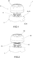
- reference numeral 1 indicates as a whole a packaging for containing a substance, in particular for containing a food liquid.
- Packaging 1 comprises a packaging body 2 preferably consisting of film walls.
- the packaging body 2 consists of a pair of facing side walls 2a, 2b, joined along a respective upper edge 4a, 4b, for example by welding.
- the side walls 2a, 2b are joined together, for example by welding, along all the peripheral edges; in alternative embodiments, the packaging body instead comprises a bottom wall and/or one or two side walls, thus forming gussetted bags.
- Packaging 1 further comprises a spout 6, applied to the packaging body 2, and a closure 8 applicable to spout 6 to close it.
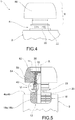
- Spout 6 comprises tubular body 10 that extends along a rectilinear main axis X, for example coincident with the central axis of the inner cylindrical side wall, between an entry end 12 and a dispensing end 14.
- spout 6 comprises a connection portion 16, in correspondence of the entry end 12 of the tubular body 10, for the sealed connection with the packaging body 2.
- connection portion 16 has connection faces 18a, 18b on opposite sides with respect to the main axis X, intended for the application of portions of the upper edges 4a, 4b of the side walls 2a, 2b.
- spout 6 From the entry end 12 towards the dispensing end 14, spout 6 also comprises a first plate 20, adjacent to the connection portion 16, and a second plate 22, axially spaced from the first plate 20, substantially parallel to the latter.
- Said plates 20, 22 have a prevailing extension of imaginary planes substantially perpendicular to the main axis X.
- Spout 6 further comprises a main abutment 24, for example made in the form of a ring, continuous or in separate sectors, axially spaced from the second plate 22.
- the main abutment 24 has a frusto-conical side surface 26, tapered towards the entry end of the tubular body 10, and is flanked by a main annular recess 28, undercut with respect to abutment 24.
- spout 6 comprises a thread 30 external to the tubular body 10, for screwing closure 8.
- closure 8 comprises a tamper-evident band 40.
- the tamper-evident band 40 comprises a fixed annular band 42 directly engageable by the main abutment 24 of spout 6 so that the axial translation thereof is prevented.
- the fixed band 42 has a free end 44 bent radially internally or enlarged with respect to the remaining part, so that it is at least partially received in the main recess 28.
- the fixed band 42 has a flared wall 46 internally having an annular frusto-conical side surface 48 converging in the unscrewing direction of closure 8 from spout 6.
- Closure 8 further comprises a movable body 50 which, during the unscrewing from spout 6, undergoes an axial translation that separates it from the spout itself.
- the movable body 50 When the tamper-evident band is inviolate, the movable body 50 is connected to the fixed band 42 through a weakened portion 52 of the tamper-evident band 40, in which an annular fixed edge 49 of the fixed band 42 and a movable edge 51 of the movable body 50 are joined.
- the tamper-evident band 40 comprises a cylindrical shank 54 of the movable body 50, joined to the fixed band 42 through the weakened portion 52; said weakened portion 52 is formed as a portion of reduced diameter by virtue of a radial notch 56 made externally.
- the movable body 50 comprises a handle 60 adapted to be grasped by a hand to perform the unscrewing of the closure, and an inner casing 62, from which said shank 54 projects axially, joined to handle 60 through a plurality of angularly spaced fins 64, between which passages 66 are formed between the inner casing 62 and handle 60, generally for anti-choking purpose.
- the tamper-evident band 40 further comprises a tamper-evident ring 70 which, with the tamper-evident band inviolate, is housed in the compartment delimited by the fixed band 42 and is therefore hidden from view.
- the tamper-evident ring 70 is made integral with the movable body 50 of closure 8, so that by unscrewing the latter, it undergoes an axial translation that makes it slip off from the spout.
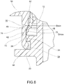
- the tamper-evident ring 70 externally has a maximum diameter Dmax greater than the minimum diameter Dmin of the side surface 48 of the flared wall 46 of the fixed band 42, so that during the axial translation due to the unscrewing, it can pop out of the fixed band 42.
- the tamper-evident ring 70 comprises a tamper-evident wall 72 having a frusto-conical outer surface 74, converging in the direction of translation of the movable body 50 during the unscrewing, for example parallel to the side surface 48 of the flared wall 46 of the fixed band 42.
- closure 8 comprises a cap 80 having a bottom 82 and an annular cap wall 84, having an axial extension.
- Bottom 82 preferably forms the closure for the mouth of the tubular body 10 of spout 6, while the end projection of the cap wall 84 forms said tamper-evident ring 70.
- cap wall 84 internally has a thread for screwing with thread 30 of spout 6.
- Cap 80 is made integral in translation and rotation to the movable body 50 of closure 8.
- cap 80 is at least partially received in casing 62 of the movable body 50, so that the tamper-evident ring body 70 is still housed inside the compartment delimited by the fixed band 43.
- said cap 80 is provided, for example on the outer surface of the cap wall 84, for example proximate to bottom 82, with a plurality of circumferential grooves 90, in which respective circumferential projections provided in casing 62 of the movable body 50 are snap-received.
- said cap 80 is provided, for example on the outer surface of the cap wall 84, for example adjacent to the tamper-evident ring 70, with a plurality of axial grooves 92, in which respective axial projections provided in casing 62 of the movable body 50 are snap-received.
- Cap 80 is made in a single piece, for example by injection moulding, of plastic material.
- the group consisting of the movable body 50 and the fixed band 42 is made in a single piece, for example by injection moulding, of plastic material.
- the spout is made in a single piece, for example by injection moulding, of plastic material.
- the cap is inserted into the inner casing 62 of the movable body 50, thus achieving the complete closure 8.
- the closure is screwed to the tubular body 10 of spout 6 and during such screwing, the free ends 44 of the fixed band 52 snaps into the main recess 28, due to the flared profile of the side surface 26 of abutment 24.
- the unscrewing of closure 8 makes the movable body 50 translate in the direction of extraction from the tubular body 10 of spout 6.
- the fixed band 42 is urged to translate in the same direction, since it is initially integral with the movable body, but it is prevented from translating by the engagement between the free end 44 and the main abutment 24 of spout 6.
- the weakened portion 52 thus undergoes a rupture, which makes the movable body 50 separate axially from the fixed band 42.
- the tamper-evident ring 70 first undergoes a deformation which makes it narrow and then, popped out of the fixed band, an elastic return to an undeformed condition.
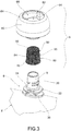
- the tamper-evident ring 70 is prevented from returning into the fixed band, arranging itself in a clear manner between the fixed edge 49 and the movable edge 51, separate and axially spaced apart. The violation of the seal is thus evident.
- the colour of the tamper-evident ring 70 selected so as to stand out with respect to the colour of the fixed band 42 and the movable body 50, contributes to make the tamper-evident ring more evident.
- the tamper-evident ring 70 is integral in translation with the movable body 50 of closure 8.
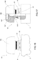
- the tamper-evident band 40 instead comprises a tamper-evident bushing 100, in turn comprising a tamper-evident ring 170, which remains fixed to the spout during the translation of a movable body 50 of closure 8 during the unscrewing.
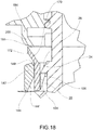
- the tamper-evident bushing 100 comprises an annular base wall 102, which extends around the tubular body 10 of spout 6, and an annular engagement tooth 104, circumferentially continuous or divided into sectors, protruding radially internally from the base wall 102, so as to achieve a coupling with the main abutment 24 of spout 6; the axial translation of the tamper-evident bushing 100, in the unscrewing direction, is thus prevented or limited.
- the engagement tooth 104 has a frusto-conical side surface 106 converging in the unscrewing translation direction of the movable body 50, so as to form a snap engagement with the main abutment 24, thus housing at least partially in the main recess 28.
- the tamper-evident bushing 100 further comprises said tamper-evident ring 170, projecting axially and radially outwardly from the base wall 102.
- the tamper-evident ring 170 comprises a tamper-evident wall 172 having a frusto-conical outer surface 174, diverging in the unscrewing translation direction of the movable body 50.
- the movable body 50 of closure 8 which during the unscrewing from spout 6 undergoes an axial translation that makes it separate from the spout itself, comprises an annular shank 154, which extends around the tubular body 10 of spout 6.
- the tamper-evident band 40 comprises a movable band 200 integral with the movable body 50, for example protruding axially from shank 154, and an annular fixed band 142, which extends around the tubular body 10 of spout 6.
- the fixed band 142 and the movable band 200 are joined together through a weakened portion 152, in which an annular fixed edge 149 of the fixed band 142 and a movable edge 151 of the movable body 200 are joined.
- the weakened portion 152 is formed as a reduced diameter portion by virtue of an annular radial notch 156 externally formed between the movable band 100 and the fixed band 142.
- the movable band 200 and the fixed band 142 are radially outwardly spaced from the tubular body 10 of spout 6, annularly delimiting a compartment in which the tamper-evident bushing 100 is housed.
- the base wall 102 of bushing 100 is arranged radially between the fixed band 142 and the main abutment 24 of the tubular body 10, while the tamper-evident ring 170 is arranged radially between the movable band 200 and said tubular body 10.
- the tamper-evident ring 170 protrudes radially outwardly with respect to the weakened portion 152 that joins the movable band 200 and the fixed band 142, so as to form an obstacle which limits the axial translation in the unscrewing direction of said fixed band 142.
- the tamper-evident ring 170 is anchored to the tubular body 10 through the engagement tooth 104 engaged with the main abutment 24, whereby the fixed band 142 is indirectly constrained to the tubular body 10 and substantially prevented from the axial translation for unscrewing.
- the movable band 200 internally has a frusto-conical side surface 248 diverging in the unscrewing direction of the movable body 50 from spout 6.
- the tamper-evident ring 170 cooperates with the movable band 200 through said side surface 248, into contact with the outer surface 174 of the tamper-evident ring 170.
- the fixed band 142 and the movable band 200 internally have a profile comprising:
- the movable body 50 comprises a handle 160 adapted to be grasped by a hand to perform the unscrewing of the closure, and an inner casing 162, from which the movable band 200 projects axially, joined to handle 160 through a plurality of angularly spaced fins 164, between which passages 166 are formed between the inner casing 162 and handle 160, generally for anti-choking purpose.
- casing 162 is provided with a bottom 162', which forms the closure for the mouth of the tubular body 10 of spout 6, and an inner thread 162" for screwing to said tubular body 10.
- the tamper-evident bushing 170 is made in a single piece, for example by injection moulding, of plastic material.
- the group consisting of the movable body 50, the movable band 200 and the fixed band 142 is made in a single piece, for example by injection moulding, of plastic material.
- the spout is made in a single piece, for example by injection moulding, of plastic material.
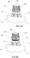
- bushing 170 is inserted into the movable band 200 and the fixed band 142, thus achieving the complete closure 8.
- the guiding surface 144' of the fixed band 142 allows the insertion of bushing 100 from the side of the tamper-evident ring 170, so that said ring 170 first shrinks, and then widens in the compartment defined by the movable band 200.
- the closure is screwed to the tubular body 10 of spout 6 and during such screwing, the free ends 44 of the fixed band 52 snaps into the main recess 28, due to the flared profile of the side surface 26 of abutment 24.
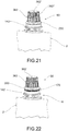
- the unscrewing of closure 8 makes the movable body 50 translate in the direction of extraction from the tubular body 10 of spout 6.
- the fixed band 142 is urged to translate in the same direction, since it is initially integral with the movable body 50 through the weakened portion 142, but it is prevented from translating by the anchoring to the main abutment 24 through bushing 170.
- the weakened portion 152 thus undergoes a rupture, which makes the movable body 50 separate axially from the fixed band 142.
- the movable body 50 in translation drags the movable band 200 therewith, so that the tamper-evident ring 170, by cooperating with the side surface 248 of the movable band 200, snaps out of the movable band 200, thus becoming visible from the outside.
- the tamper-evident ring 170 first undergoes a deformation which makes it shrink and then, popped out of the movable band, an elastic return to an undeformed condition.
- the tamper-evident ring 170 is prevented from returning into the movable band, arranging itself in a clear manner between the fixed edge 149 of the fixed band 142 and the movable edge 151 of the movable band 200, separate and axially spaced apart. The violation of the seal is thus evident.
- the colour of the tamper-evident ring 170 selected so as to stand out with respect to the colour of the fixed band 142 and the movable body 50, contributes to make the tamper-evident ring more evident.
- the movable body 50 consists of a casing 362, provided with a bottom 362' and a side wall 362" projecting from bottom 362'.
- cap 80 is housed inside casing 362 and the tamper-evident band is provided with the structural and functional features described for the embodiment according to figures 1 to 9 .
- bottom 362' of casing 362 closes the mouth of the tubular body 10 of spout 6, the end portion of the side wall 362" constitutes the movable band 200 and the tamper-evident band is provided with the structural and functional features described for the embodiment according to figures 10 to 18 .
- the closure with tamper-evident band according to the present invention overcomes the drawbacks mentioned with reference to the prior art, since the violation of the band is very evident.
- the tamper-evident ring especially if selected so as to have a colour contrasting with the other components of the closure, is immediately evident.
Landscapes
- Engineering & Computer Science (AREA)
- Mechanical Engineering (AREA)
- Closures For Containers (AREA)
- Cartons (AREA)
- Packages (AREA)
- Seal Device For Vehicle (AREA)
Claims (8)
- Verschluss (8), umfassend ein manipulationssicheres Band (40), der für eine Verpackung (1) zum Einschließen von Flüssigkeiten dienen soll, insbesondere von Getränken für Kinder, wie etwa Säfte und Fruchtmus, Joghurt, Limonaden und dergleichen, wobei der Verschluss auf einem Ausgießer (6) angebracht werden kann, der mit einem rohrförmigen Körper (10) versehen ist, der mit einem ringförmigen Hauptwiderlager (24) versehen ist und ferner umfasst:- ein festsitzendes Band (42, 142), in welches das Hauptwiderlager (24) direkt oder indirekt eingreifen kann, um die axiale Verschiebung in der Abschraubrichtung des Verschlusses zu begrenzen;- einen beweglichen Körper (50), umfassend ein Gehäuse (62, 162), das auf den rohrförmigen Körper (10) des Ausgießers (6) geschraubt werden kann, wobei das festsitzende Band (42, 142), wenn das manipulationssichere Band (40) unberührt ist, mit dem beweglichen Körper (50) durch einen geschwächten Abschnitt (52, 152) verbunden ist, der sich an einen festsitzenden Rand (49, 149) des festsitzenden Bands (42, 142) und einen beweglichen Rand (51, 151) des beweglichen Körpers (50) anfügt;- einen manipulationssicheren Ring (70, 170), der in einem ringförmigen, manipulationssicheren Rand (71, 171) endet und der, wenn das manipulationssichere Band (40) unberührt ist, in einem Innenfach des Verschlusses (8) von außen unsichtbar untergebracht ist;
wobei der geschwächte Abschnitt (52, 152) geeignet ist, aufgrund des Abschraubens des Verschlusses (8) von dem Ausgießer (6) zu reißen, und der manipulationssichere Ring (70, 170) aus dem Innenfach herausspringt und verfügbar ist, sodass er, wenn das manipulationssichere Band (40) zerbrochen ist, den festsitzenden Rand (49, 149) des festsitzenden Bands (42, 142) und den beweglichen Rand (51, 151) des beweglichen Körpers (50) trennt. - Verschluss nach Anspruch 1, wobei er einrastend auf dem Ausgießer (6) angebracht werden kann.
- Verschluss nach Anspruch 2, wobei das festsitzende Band (42) ein freies Ende (44) aufweist, das radial nach innen oder vergrößert in Bezug auf den restlichen Teil ist, sodass es mindestens teilweise in einer Hauptaussparung (28), die als Hinterschneidung von dem Hauptwiderlager (24) gebildet wird, einrastend aufgenommen wird.
- Verschluss nach einem der vorhergehenden Ansprüche, wobei der manipulationssichere Ring (70) einstückig mit dem beweglichen Körper (50) gebildet ist, wenn die Dichtung unberührt ist, in einem Fach aufgenommen ist, das von dem festsitzenden Band (42) begrenzt wird, und aus dem Fach aufgrund des Abschraubens des Verschlusses (8) herausspringt.
- Verschluss nach Anspruch 1 oder 2, wobei der manipulationssichere Ring (170) auf dem Hauptwiderlager (24) des Ausgießers (6) verankert werden kann, wodurch eine Verschiebung aufgrund des Abschraubens des Verschlusses (8) verhindert wird.
- Verschluss nach Anspruch 5, wobei der bewegliche Körper (50) ein bewegliches Band (200) umfasst, das, wenn die Dichtung unberührt ist, an das festsitzende Band (142) durch den geschwächten Abschnitt (152) angefügt ist, der manipulationssichere Ring (170) in einem Fach aufgenommen ist, das von dem beweglichen Band (200) begrenzt wird, und aus dem Fach aufgrund des Abschraubens des Verschlusses (8) herausspringt.
- Verschluss nach Anspruch 5 oder 6, wobei das festsitzende Band (142) in axialer Verschiebung mittels einer manipulationssicheren Buchse (100) begrenzt wird, von welcher der manipulationssichere Ring (170) ein Teil ist, wobei die manipulationssichere Buchse (100) in das Hauptwiderlager (24) des Ausgießers (6) einrastend eingreifen kann.
- Baugruppe, umfassend:- einen Ausgießer (6), der auf einem Verpackungskörper (2) mit Folienwänden angebracht werden kann, umfassend:i) einen rohrförmigen Körper (10), der sich entlang einer geradlinigen Hauptachse (X) zwischen einem Eintrittsende (12) und einem Ausgabeende (14) erstreckt;ii) einen Verbindungsabschnitt (16) entsprechend dem Eintrittsende (12) des rohrförmigen Körpers (10), für eine dichte Verbindung mit dem Verpackungskörper (2);iii) ein ringförmiges Hauptwiderlager (24), das von dem rohrförmigen Körper (10) radial nach außen vorspringt;- einen Verschluss (8) mit einem manipulationssicheren Band (40), der auf dem Ausgießer (6) angebracht ist, umfassend:i) ein festsitzendes, ringförmiges Band (42), das in das Hauptwiderlager (24) des Ausgießers (6) einrastend eingreift;ii) einen beweglichen Körper (50), der auf den rohrförmigen Körper (10) des Ausgießers (6) geschraubt werden kann, wobei das festsitzende Band (42, 142), wenn das manipulationssichere Band unberührt ist, mit dem beweglichen Körper (50) durch einen geschwächten Abschnitt (52, 152) verbunden ist, der sich an einen festsitzenden Rand (49, 149) des festsitzenden Bands (42, 142) und einen beweglichen Rand (51, 151) des beweglichen Körpers (50) anfügt;iii) einen manipulationssicheren Ring (70), der einstückig mit dem beweglichen Körper (50) gebildet ist, in einem ringförmigen, manipulationssicheren Rand (50) endet und, wenn das manipulationssichere Band unberührt ist, in einem Innenfach untergebracht ist, das von dem festsitzenden Band (42) begrenzt wird, um von außen unsichtbar zu sein;
wobei der geschwächte Abschnitt (52) geeignet ist, aufgrund des Abschraubens des Verschlusses (8) von dem Ausgießer (6) zu reißen, und der manipulationssichere Ring (70) aus dem Innenfach herausspringt und verfügbar ist, sodass er, wenn die Dichtung zerbrochen ist, den festsitzenden Rand (49) des festsitzenden Bands (42) und den beweglichen Rand (51) des beweglichen Körpers (50) trennt.
Applications Claiming Priority (2)
| Application Number | Priority Date | Filing Date | Title |
|---|---|---|---|
| IT102016000080146A IT201600080146A1 (it) | 2016-07-29 | 2016-07-29 | Chiusura con sigillo di garanzia |
| PCT/IB2017/054397 WO2018020365A1 (en) | 2016-07-29 | 2017-07-20 | Closure with tamper-evident band |
Publications (2)
| Publication Number | Publication Date |
|---|---|
| EP3490905A1 EP3490905A1 (de) | 2019-06-05 |
| EP3490905B1 true EP3490905B1 (de) | 2020-08-12 |
Family
ID=58159230
Family Applications (1)
| Application Number | Title | Priority Date | Filing Date |
|---|---|---|---|
| EP17761112.6A Active EP3490905B1 (de) | 2016-07-29 | 2017-07-20 | Verschluss mit manipulationssicherem band |
Country Status (19)
| Country | Link |
|---|---|
| US (1) | US11577887B2 (de) |
| EP (1) | EP3490905B1 (de) |
| JP (1) | JP6955547B2 (de) |
| KR (1) | KR102364809B1 (de) |
| CN (1) | CN109562877B (de) |
| AU (1) | AU2017304110B2 (de) |
| BR (1) | BR112018076963B1 (de) |
| CA (1) | CA3029799C (de) |
| CL (1) | CL2018003802A1 (de) |
| CR (1) | CR20180601A (de) |
| DK (1) | DK3490905T3 (de) |
| ES (1) | ES2831087T3 (de) |
| IT (1) | IT201600080146A1 (de) |
| MX (1) | MX386315B (de) |
| PT (1) | PT3490905T (de) |
| RU (1) | RU2732658C2 (de) |
| UA (1) | UA125219C2 (de) |
| WO (1) | WO2018020365A1 (de) |
| ZA (1) | ZA201900014B (de) |
Families Citing this family (14)
| Publication number | Priority date | Publication date | Assignee | Title |
|---|---|---|---|---|
| IT201600080146A1 (it) * | 2016-07-29 | 2018-01-29 | Guala Pack Spa | Chiusura con sigillo di garanzia |
| ES2917204T3 (es) * | 2017-12-18 | 2022-07-07 | Guala Pack Spa | Boquilla y conjunto de tapón-boquilla |
| WO2019172339A1 (ja) * | 2018-03-06 | 2019-09-12 | 株式会社細川洋行 | 口栓部の構造および包装体 |
| IT201800009967A1 (it) * | 2018-10-31 | 2020-05-01 | Guala Pack Spa | Chiusura per cannuccia di un imballo flessibile a pareti sottili |
| IT201900001829A1 (it) * | 2019-02-08 | 2020-08-08 | Guala Pack Spa | Chiusura per cannuccia di un imballo flessibile a pareti sottili |
| IT201900002103A1 (it) | 2019-02-13 | 2020-08-13 | Guala Pack Spa | Tappo per cannuccia per un imballo flessibile a pareti sottili |
| CN111532581B (zh) * | 2020-06-01 | 2024-08-09 | 东莞市雄杰实业有限公司 | 一种防盗卡扣及一种防盗包装盒 |
| IT202000019939A1 (it) * | 2020-08-11 | 2022-02-11 | Guala Pack Spa | Chiusura per una cannuccia di un imballo a pareti sottili |
| IT202100021059A1 (it) * | 2021-08-04 | 2023-02-04 | Guala Pack Spa | Chiusura per una cannuccia di un imballo a pareti sottili |
| US12263996B2 (en) | 2021-09-17 | 2025-04-01 | Cheer Pack North America LLC | Tamper-evident cap |
| US11702252B2 (en) | 2021-09-17 | 2023-07-18 | Cheer Pack North America LLC | Tamper-evident closure for container |
| USD1047691S1 (en) | 2022-10-06 | 2024-10-22 | Cheer Pack North America LLC | Cap |
| USD1037095S1 (en) | 2022-10-20 | 2024-07-30 | Rock Solid Industries International (Pty) Ltd. | Glass slider |
| USD1108334S1 (en) | 2022-10-20 | 2026-01-06 | Rock Solid Industries International (Pty) Ltd. | Side glass |
Family Cites Families (65)
| Publication number | Priority date | Publication date | Assignee | Title |
|---|---|---|---|---|
| DE1432215C3 (de) * | 1964-09-15 | 1973-10-11 | Merck Patent Gmbh, 6100 Darmstadt | Origmalschraubverschlußanordnung |
| US4402418A (en) * | 1981-11-27 | 1983-09-06 | Ethyl Products Company | Tamperproof closure |
| WO1983003809A1 (fr) * | 1982-04-23 | 1983-11-10 | Cebal | Capsule de bouchage a vis, en plastique, a bande d'inviolabilite perfectionnee |
| US4530437A (en) * | 1982-05-03 | 1985-07-23 | Owens-Illinois, Inc. | Tamperproof package |
| CH649057A5 (fr) * | 1982-06-10 | 1985-04-30 | Stericric Sa | Flacon pour liquides apte a supporter une sterilisation terminale, muni d'un dispositif de fermeture inviolable. |
| US4470513A (en) * | 1982-09-23 | 1984-09-11 | Ethyl Molded Products Company | Tamper-indicating closure |
| FR2563500B1 (fr) * | 1984-04-26 | 1986-11-28 | Astra Plastique | Recipient a jeter apres utilisation et destine plus particulierement a l'alimentation des nourrissons |
| US4669124A (en) * | 1984-05-23 | 1987-05-26 | Yoken Co., Ltd. | Beverage container with tamperproof screwthread cap |
| US4550844A (en) * | 1984-06-22 | 1985-11-05 | Owens-Illinois, Inc. | Tamper resistant closure with tear-off band |
| US4759456A (en) * | 1986-10-31 | 1988-07-26 | Owens-Illinois Closure Inc. | Tamper-indicating package and plastic closure therefore |
| GB8627251D0 (en) * | 1986-11-14 | 1986-12-17 | Grace W R & Co | Tamper-evident closure device |
| US4848614A (en) * | 1987-11-13 | 1989-07-18 | General Kap Corporation | Tamper-evident plastic closure |
| US4805791A (en) * | 1988-05-04 | 1989-02-21 | Continental White Cap, Inc. | Band with lock ring for tamper-evident cap |
| FR2631934B1 (fr) * | 1988-05-30 | 1990-12-14 | Astra Plastique | Dispositif de bouchage comprenant un bouchon et une bague d'inviolabilite, et procede pour sa fabrication |
| ES2101741T3 (es) * | 1989-12-28 | 1997-07-16 | Zapata Innovative Closures Inc | Tapas testigo de manipulacion indebida y metodos para fabricar estas tapas. |
| IT1242923B (it) * | 1990-10-17 | 1994-05-18 | Bormioli Metalplast Spa | Capsula in plastica in due pezzi, per bottiglie |
| DE4201997C1 (de) * | 1992-01-25 | 1992-12-10 | Stella Kunststofftechnik Gmbh, 6228 Eltville, De | |
| US5346082A (en) * | 1992-06-12 | 1994-09-13 | Anchor Hocking Packaging Co. | Composite closure with sealing force indicating means and ratchet operated tamper indicating band |
| US5356019A (en) * | 1992-10-14 | 1994-10-18 | Crown Cork & Seal Company, Inc. | Tamper indicating plastic closure |
| AU683857B2 (en) * | 1992-11-13 | 1997-11-27 | Beeson And Sons Limited | Improvements relating to a tamper evident ring for a container closure |
| DK0636551T3 (da) * | 1993-07-12 | 1996-08-26 | Nestle Sa | Beholderlukke med sikkerhedsring |
| TW279835B (en) | 1995-03-22 | 1996-07-01 | Precision Valve Corp | Tamper-evident closure with captive band |
| US5979682A (en) * | 1997-04-14 | 1999-11-09 | Zumbuhl; Bruno | Tab construction for closures having tamper evident rings |
| US5971182A (en) * | 1998-05-18 | 1999-10-26 | Creative Packaging Corp. | Closure with tamper-evident band |
| BR9911550A (pt) * | 1998-06-24 | 2001-05-08 | Alpha Entpr Inc | Dispositivo de segurança de garrafa para uso com uma garrafa tendo um gargalo |
| US7059485B1 (en) * | 1999-06-03 | 2006-06-13 | Reidenbach Bryan L | Tamper-resistant bottle closure |
| JP2001055258A (ja) * | 1999-08-17 | 2001-02-27 | Santen Pharmaceut Co Ltd | 容器の不正開封防止用具 |
| US6325227B1 (en) * | 2000-03-20 | 2001-12-04 | Phoenix Closures, Inc. | Tamper-indicating closure with horizontal undercuts |
| US6575319B2 (en) * | 2000-04-27 | 2003-06-10 | Bruno Zumbuhl | Tab construction for threaded closures having tamper-indicating ring |
| US20020096485A1 (en) * | 2000-12-04 | 2002-07-25 | Bruno Zumbuhl | Tamper ring locking tab construction |
| WO2003093129A1 (en) * | 2002-05-02 | 2003-11-13 | Bormioli Rocco & Figlio S.P.A. | Child-proof capsule with security strip |
| US20040026288A1 (en) * | 2002-08-12 | 2004-02-12 | Bruno Zumbuhl | Threaded closure with tamper indicating ring |
| KR100553806B1 (ko) * | 2002-09-27 | 2006-02-22 | 가부시키가이샤 니프코 | 병형상을 이루는 용기의 캡 |
| ITMO20030232A1 (it) * | 2003-08-07 | 2005-02-08 | Sacmi | Mezzi a capsula |
| MY137973A (en) * | 2003-10-31 | 2009-04-30 | Obrist Closures Switzerland | A tamper-evident closure |
| ITMO20040201A1 (it) * | 2004-07-30 | 2004-10-30 | Sacmi | Capsula per contenitori. |
| US7527161B2 (en) * | 2004-12-01 | 2009-05-05 | Fisher Scientific Company L.L.C. | Cap closure |
| EA200500559A1 (ru) * | 2005-04-28 | 2006-04-28 | Иностранное Унитарное Производственное Предприятие Компании "Белкапс Бетайлингус Гмбх" Белкэпс | Укупорочное устройство для бутылки (варианты) |
| ITBS20060190A1 (it) * | 2006-10-27 | 2008-04-28 | Guala Pack Spa | Tappo per contenitore munito di sigillo di garanzia |
| JP4921944B2 (ja) * | 2006-12-07 | 2012-04-25 | 株式会社細川洋行 | 口栓ユニット及びそれを用いた袋体 |
| ES2345909T3 (es) * | 2007-02-27 | 2010-10-05 | Guala Closures S.P.A. | Cierre inviolable para recipientes provistos de un cuello roscado. |
| CN201040619Y (zh) * | 2007-04-18 | 2008-03-26 | 青岛明星食品包装科技有限公司 | 扭开双层断点、露环式三重塑料防伪瓶盖 |
| US8251236B1 (en) * | 2007-11-02 | 2012-08-28 | Berry Plastics Corporation | Closure with lifting mechanism |
| CN201292070Y (zh) | 2008-03-05 | 2009-08-19 | 石都股份有限公司 | 带显启机构的容器盖 |
| CN201195602Y (zh) * | 2008-03-24 | 2009-02-18 | 赖文生 | 瓶盖及瓶口之结构 |
| WO2009128095A1 (en) * | 2008-04-14 | 2009-10-22 | Creative Gcl S.R.L. | Compact optical closure |
| CN201201759Y (zh) | 2008-08-19 | 2009-03-04 | 成都天坤包装有限责任公司 | 防伪瓶盖 |
| DE102010039036A1 (de) * | 2010-08-06 | 2012-02-09 | Bericap Gmbh & Co. Kg | Schraubverschluss mit Flexband |
| US8292104B2 (en) * | 2011-02-14 | 2012-10-23 | Living Fountain Plastic Industrial Co., Ltd. | Safety bottle cap structure with anti-burglary tearing flange |
| US20130202227A1 (en) * | 2012-02-02 | 2013-08-08 | Alexis DaCosta | Articles of manufacture for sealing flexible and non-ridged containers |
| JP6094078B2 (ja) * | 2012-07-12 | 2017-03-15 | 凸版印刷株式会社 | 口栓 |
| ITBS20120110A1 (it) * | 2012-07-18 | 2014-01-19 | Guala Pack Spa | Tappo per contenitori, ad esempio per bottigliette o imballi flessibili, ad esempio per bevande per bambini |
| US9016524B2 (en) | 2012-09-17 | 2015-04-28 | Owens-Brockway Glass Container Inc. | Tamper-evident anti-refill dispensing fitment for a container |
| GB201307034D0 (en) | 2013-04-18 | 2013-05-29 | Obrist Closures Switzerland | Tamper-evident closure |
| EP3134326B1 (de) * | 2014-04-24 | 2019-03-06 | Obrist Closures Switzerland GmbH | Verbesserungen an oder im zusammenhang mit manipulationssicheren verschlüssen |
| US9533802B2 (en) * | 2014-10-31 | 2017-01-03 | Silgan White Cap LLC | Closure with tamper band and spout |
| WO2016141311A1 (en) * | 2015-03-04 | 2016-09-09 | Specialty Lubricants Corp. | Packaging closure adapter |
| GB201509390D0 (en) * | 2015-06-01 | 2015-07-15 | Obrist Closures Switzerland | A closure |
| US10486867B2 (en) * | 2015-09-25 | 2019-11-26 | Amcor Rigid Plastics Usa, Llc | Closure system for container |
| GB201601789D0 (en) * | 2016-02-01 | 2016-03-16 | Obrist Closures Switzerland | Improvements in or relating to tamper-evident closures |
| US9938050B2 (en) * | 2016-05-13 | 2018-04-10 | Silgan White Cap LLC | Closure with hinged tamper band |
| IT201600080146A1 (it) * | 2016-07-29 | 2018-01-29 | Guala Pack Spa | Chiusura con sigillo di garanzia |
| US11014715B2 (en) * | 2016-12-19 | 2021-05-25 | Joongang Platec Co.,Ltd | Safety cap spout |
| ES2917204T3 (es) * | 2017-12-18 | 2022-07-07 | Guala Pack Spa | Boquilla y conjunto de tapón-boquilla |
| WO2019172339A1 (ja) * | 2018-03-06 | 2019-09-12 | 株式会社細川洋行 | 口栓部の構造および包装体 |
-
2016
- 2016-07-29 IT IT102016000080146A patent/IT201600080146A1/it unknown
-
2017
- 2017-07-20 JP JP2019504771A patent/JP6955547B2/ja active Active
- 2017-07-20 WO PCT/IB2017/054397 patent/WO2018020365A1/en not_active Ceased
- 2017-07-20 CR CR20180601A patent/CR20180601A/es unknown
- 2017-07-20 US US16/320,917 patent/US11577887B2/en active Active
- 2017-07-20 KR KR1020197003004A patent/KR102364809B1/ko active Active
- 2017-07-20 CN CN201780045784.1A patent/CN109562877B/zh active Active
- 2017-07-20 MX MX2018016239A patent/MX386315B/es unknown
- 2017-07-20 DK DK17761112.6T patent/DK3490905T3/da active
- 2017-07-20 PT PT177611126T patent/PT3490905T/pt unknown
- 2017-07-20 CA CA3029799A patent/CA3029799C/en active Active
- 2017-07-20 ES ES17761112T patent/ES2831087T3/es active Active
- 2017-07-20 UA UAA201902003A patent/UA125219C2/uk unknown
- 2017-07-20 BR BR112018076963-0A patent/BR112018076963B1/pt active IP Right Grant
- 2017-07-20 AU AU2017304110A patent/AU2017304110B2/en active Active
- 2017-07-20 RU RU2019105321A patent/RU2732658C2/ru active
- 2017-07-20 EP EP17761112.6A patent/EP3490905B1/de active Active
-
2018
- 2018-12-21 CL CL2018003802A patent/CL2018003802A1/es unknown
-
2019
- 2019-01-02 ZA ZA2019/00014A patent/ZA201900014B/en unknown
Non-Patent Citations (1)
| Title |
|---|
| None * |
Also Published As
| Publication number | Publication date |
|---|---|
| PT3490905T (pt) | 2020-10-15 |
| BR112018076963B1 (pt) | 2022-09-27 |
| US20190168924A1 (en) | 2019-06-06 |
| AU2017304110B2 (en) | 2023-04-06 |
| JP2019523185A (ja) | 2019-08-22 |
| ZA201900014B (en) | 2019-08-28 |
| WO2018020365A1 (en) | 2018-02-01 |
| CN109562877B (zh) | 2021-09-24 |
| MX2018016239A (es) | 2019-04-22 |
| EP3490905A1 (de) | 2019-06-05 |
| IT201600080146A1 (it) | 2018-01-29 |
| CR20180601A (es) | 2019-02-15 |
| DK3490905T3 (da) | 2020-10-26 |
| BR112018076963A2 (pt) | 2019-04-02 |
| KR20190031249A (ko) | 2019-03-25 |
| NZ749766A (en) | 2024-05-31 |
| AU2017304110A1 (en) | 2019-01-24 |
| MX386315B (es) | 2025-03-18 |
| JP6955547B2 (ja) | 2021-10-27 |
| CA3029799A1 (en) | 2018-02-01 |
| CA3029799C (en) | 2024-10-01 |
| ES2831087T3 (es) | 2021-06-07 |
| RU2732658C2 (ru) | 2020-09-21 |
| RU2019105321A3 (de) | 2020-09-01 |
| RU2019105321A (ru) | 2020-08-28 |
| US11577887B2 (en) | 2023-02-14 |
| UA125219C2 (uk) | 2022-02-02 |
| CL2018003802A1 (es) | 2019-02-22 |
| CN109562877A (zh) | 2019-04-02 |
| KR102364809B1 (ko) | 2022-02-18 |
Similar Documents
| Publication | Publication Date | Title |
|---|---|---|
| EP3490905B1 (de) | Verschluss mit manipulationssicherem band | |
| US5215204A (en) | Tamper evident closure with hinged band | |
| US5678735A (en) | Rupturable stopper for a pouring spout | |
| EP3325366B1 (de) | Originalitätsverschluss | |
| CN105008236A (zh) | 用于喷口的具有两个铰链的封盖 | |
| EP1582475B1 (de) | Originalitätsverschlussvorrichtung | |
| EP4185539B1 (de) | Verschluss für eine dünnwandige verpackung mit einem ausgiesser | |
| UA128312C2 (uk) | Закупорювальний пристрій для шийки гнучкої тонкостінної упаковки | |
| EP4196409B1 (de) | Verschluss für einen ausguss in einer dünnwandigen verpackung | |
| JPS59500961A (ja) | 容器蓋 | |
| KR100985326B1 (ko) | 개봉 흔적이 남는 밀봉장치를 구비한 액체용기용 클로저 | |
| RU79528U1 (ru) | Укупорочное устройство | |
| WO2001064538A1 (en) | A security closure for bottles and the like | |
| RU2823610C1 (ru) | Укупорочное средство для тонкостенной упаковки с горлышком | |
| RU79875U1 (ru) | Укупорочное устройство | |
| EP3133026B1 (de) | Verschlusskappe für glasflaschen | |
| US20220250813A1 (en) | Device for closing a threaded neck of a container providing tamper-evidence | |
| CN112824250A (zh) | 瓶子和瓶子的封闭方法 | |
| HK1115568A1 (en) | Break-open valve for a container | |
| NZ552313A (en) | Beverage container valve assembly with dispensing member attachable to container neck and having flexible seal with slit(s), and a cover member |
Legal Events
| Date | Code | Title | Description |
|---|---|---|---|
| STAA | Information on the status of an ep patent application or granted ep patent |
Free format text: STATUS: UNKNOWN |
|
| STAA | Information on the status of an ep patent application or granted ep patent |
Free format text: STATUS: THE INTERNATIONAL PUBLICATION HAS BEEN MADE |
|
| PUAI | Public reference made under article 153(3) epc to a published international application that has entered the european phase |
Free format text: ORIGINAL CODE: 0009012 |
|
| STAA | Information on the status of an ep patent application or granted ep patent |
Free format text: STATUS: REQUEST FOR EXAMINATION WAS MADE |
|
| 17P | Request for examination filed |
Effective date: 20181205 |
|
| AK | Designated contracting states |
Kind code of ref document: A1 Designated state(s): AL AT BE BG CH CY CZ DE DK EE ES FI FR GB GR HR HU IE IS IT LI LT LU LV MC MK MT NL NO PL PT RO RS SE SI SK SM TR |
|
| AX | Request for extension of the european patent |
Extension state: BA ME |
|
| DAV | Request for validation of the european patent (deleted) | ||
| DAX | Request for extension of the european patent (deleted) | ||
| GRAP | Despatch of communication of intention to grant a patent |
Free format text: ORIGINAL CODE: EPIDOSNIGR1 |
|
| STAA | Information on the status of an ep patent application or granted ep patent |
Free format text: STATUS: GRANT OF PATENT IS INTENDED |
|
| INTG | Intention to grant announced |
Effective date: 20200325 |
|
| GRAS | Grant fee paid |
Free format text: ORIGINAL CODE: EPIDOSNIGR3 |
|
| GRAA | (expected) grant |
Free format text: ORIGINAL CODE: 0009210 |
|
| STAA | Information on the status of an ep patent application or granted ep patent |
Free format text: STATUS: THE PATENT HAS BEEN GRANTED |
|
| AK | Designated contracting states |
Kind code of ref document: B1 Designated state(s): AL AT BE BG CH CY CZ DE DK EE ES FI FR GB GR HR HU IE IS IT LI LT LU LV MC MK MT NL NO PL PT RO RS SE SI SK SM TR |
|
| REG | Reference to a national code |
Ref country code: CH Ref legal event code: EP |
|
| REG | Reference to a national code |
Ref country code: DE Ref legal event code: R096 Ref document number: 602017021598 Country of ref document: DE |
|
| REG | Reference to a national code |
Ref country code: IE Ref legal event code: FG4D |
|
| REG | Reference to a national code |
Ref country code: AT Ref legal event code: REF Ref document number: 1301358 Country of ref document: AT Kind code of ref document: T Effective date: 20200915 |
|
| REG | Reference to a national code |
Ref country code: PT Ref legal event code: SC4A Ref document number: 3490905 Country of ref document: PT Date of ref document: 20201015 Kind code of ref document: T Free format text: AVAILABILITY OF NATIONAL TRANSLATION Effective date: 20201009 |
|
| REG | Reference to a national code |
Ref country code: FI Ref legal event code: FGE |
|
| REG | Reference to a national code |
Ref country code: DK Ref legal event code: T3 Effective date: 20201021 |
|
| REG | Reference to a national code |
Ref country code: SE Ref legal event code: TRGR |
|
| REG | Reference to a national code |
Ref country code: NO Ref legal event code: T2 Effective date: 20200812 |
|
| REG | Reference to a national code |
Ref country code: LT Ref legal event code: MG4D |
|
| REG | Reference to a national code |
Ref country code: NL Ref legal event code: MP Effective date: 20200812 |
|
| PG25 | Lapsed in a contracting state [announced via postgrant information from national office to epo] |
Ref country code: GR Free format text: LAPSE BECAUSE OF FAILURE TO SUBMIT A TRANSLATION OF THE DESCRIPTION OR TO PAY THE FEE WITHIN THE PRESCRIBED TIME-LIMIT Effective date: 20201113 Ref country code: LT Free format text: LAPSE BECAUSE OF FAILURE TO SUBMIT A TRANSLATION OF THE DESCRIPTION OR TO PAY THE FEE WITHIN THE PRESCRIBED TIME-LIMIT Effective date: 20200812 Ref country code: HR Free format text: LAPSE BECAUSE OF FAILURE TO SUBMIT A TRANSLATION OF THE DESCRIPTION OR TO PAY THE FEE WITHIN THE PRESCRIBED TIME-LIMIT Effective date: 20200812 Ref country code: BG Free format text: LAPSE BECAUSE OF FAILURE TO SUBMIT A TRANSLATION OF THE DESCRIPTION OR TO PAY THE FEE WITHIN THE PRESCRIBED TIME-LIMIT Effective date: 20201112 |
|
| PG25 | Lapsed in a contracting state [announced via postgrant information from national office to epo] |
Ref country code: NL Free format text: LAPSE BECAUSE OF FAILURE TO SUBMIT A TRANSLATION OF THE DESCRIPTION OR TO PAY THE FEE WITHIN THE PRESCRIBED TIME-LIMIT Effective date: 20200812 Ref country code: LV Free format text: LAPSE BECAUSE OF FAILURE TO SUBMIT A TRANSLATION OF THE DESCRIPTION OR TO PAY THE FEE WITHIN THE PRESCRIBED TIME-LIMIT Effective date: 20200812 Ref country code: RS Free format text: LAPSE BECAUSE OF FAILURE TO SUBMIT A TRANSLATION OF THE DESCRIPTION OR TO PAY THE FEE WITHIN THE PRESCRIBED TIME-LIMIT Effective date: 20200812 Ref country code: IS Free format text: LAPSE BECAUSE OF FAILURE TO SUBMIT A TRANSLATION OF THE DESCRIPTION OR TO PAY THE FEE WITHIN THE PRESCRIBED TIME-LIMIT Effective date: 20201212 |
|
| PG25 | Lapsed in a contracting state [announced via postgrant information from national office to epo] |
Ref country code: SM Free format text: LAPSE BECAUSE OF FAILURE TO SUBMIT A TRANSLATION OF THE DESCRIPTION OR TO PAY THE FEE WITHIN THE PRESCRIBED TIME-LIMIT Effective date: 20200812 Ref country code: EE Free format text: LAPSE BECAUSE OF FAILURE TO SUBMIT A TRANSLATION OF THE DESCRIPTION OR TO PAY THE FEE WITHIN THE PRESCRIBED TIME-LIMIT Effective date: 20200812 |
|
| REG | Reference to a national code |
Ref country code: DE Ref legal event code: R097 Ref document number: 602017021598 Country of ref document: DE |
|
| PG25 | Lapsed in a contracting state [announced via postgrant information from national office to epo] |
Ref country code: AL Free format text: LAPSE BECAUSE OF FAILURE TO SUBMIT A TRANSLATION OF THE DESCRIPTION OR TO PAY THE FEE WITHIN THE PRESCRIBED TIME-LIMIT Effective date: 20200812 |
|
| REG | Reference to a national code |
Ref country code: ES Ref legal event code: FG2A Ref document number: 2831087 Country of ref document: ES Kind code of ref document: T3 Effective date: 20210607 |
|
| PLBE | No opposition filed within time limit |
Free format text: ORIGINAL CODE: 0009261 |
|
| STAA | Information on the status of an ep patent application or granted ep patent |
Free format text: STATUS: NO OPPOSITION FILED WITHIN TIME LIMIT |
|
| PG25 | Lapsed in a contracting state [announced via postgrant information from national office to epo] |
Ref country code: SK Free format text: LAPSE BECAUSE OF FAILURE TO SUBMIT A TRANSLATION OF THE DESCRIPTION OR TO PAY THE FEE WITHIN THE PRESCRIBED TIME-LIMIT Effective date: 20200812 |
|
| 26N | No opposition filed |
Effective date: 20210514 |
|
| PG25 | Lapsed in a contracting state [announced via postgrant information from national office to epo] |
Ref country code: SI Free format text: LAPSE BECAUSE OF FAILURE TO SUBMIT A TRANSLATION OF THE DESCRIPTION OR TO PAY THE FEE WITHIN THE PRESCRIBED TIME-LIMIT Effective date: 20200812 |
|
| REG | Reference to a national code |
Ref country code: CH Ref legal event code: PL |
|
| PG25 | Lapsed in a contracting state [announced via postgrant information from national office to epo] |
Ref country code: MC Free format text: LAPSE BECAUSE OF FAILURE TO SUBMIT A TRANSLATION OF THE DESCRIPTION OR TO PAY THE FEE WITHIN THE PRESCRIBED TIME-LIMIT Effective date: 20200812 |
|
| REG | Reference to a national code |
Ref country code: BE Ref legal event code: MM Effective date: 20210731 |
|
| PG25 | Lapsed in a contracting state [announced via postgrant information from national office to epo] |
Ref country code: LI Free format text: LAPSE BECAUSE OF NON-PAYMENT OF DUE FEES Effective date: 20210731 Ref country code: CH Free format text: LAPSE BECAUSE OF NON-PAYMENT OF DUE FEES Effective date: 20210731 |
|
| PG25 | Lapsed in a contracting state [announced via postgrant information from national office to epo] |
Ref country code: LU Free format text: LAPSE BECAUSE OF NON-PAYMENT OF DUE FEES Effective date: 20210720 |
|
| PG25 | Lapsed in a contracting state [announced via postgrant information from national office to epo] |
Ref country code: BE Free format text: LAPSE BECAUSE OF NON-PAYMENT OF DUE FEES Effective date: 20210731 |
|
| PG25 | Lapsed in a contracting state [announced via postgrant information from national office to epo] |
Ref country code: CY Free format text: LAPSE BECAUSE OF FAILURE TO SUBMIT A TRANSLATION OF THE DESCRIPTION OR TO PAY THE FEE WITHIN THE PRESCRIBED TIME-LIMIT Effective date: 20200812 |
|
| P01 | Opt-out of the competence of the unified patent court (upc) registered |
Effective date: 20230530 |
|
| REG | Reference to a national code |
Ref country code: AT Ref legal event code: UEP Ref document number: 1301358 Country of ref document: AT Kind code of ref document: T Effective date: 20200812 |
|
| PG25 | Lapsed in a contracting state [announced via postgrant information from national office to epo] |
Ref country code: HU Free format text: LAPSE BECAUSE OF FAILURE TO SUBMIT A TRANSLATION OF THE DESCRIPTION OR TO PAY THE FEE WITHIN THE PRESCRIBED TIME-LIMIT; INVALID AB INITIO Effective date: 20170720 |
|
| PG25 | Lapsed in a contracting state [announced via postgrant information from national office to epo] |
Ref country code: MK Free format text: LAPSE BECAUSE OF FAILURE TO SUBMIT A TRANSLATION OF THE DESCRIPTION OR TO PAY THE FEE WITHIN THE PRESCRIBED TIME-LIMIT Effective date: 20200812 |
|
| PG25 | Lapsed in a contracting state [announced via postgrant information from national office to epo] |
Ref country code: TR Free format text: LAPSE BECAUSE OF FAILURE TO SUBMIT A TRANSLATION OF THE DESCRIPTION OR TO PAY THE FEE WITHIN THE PRESCRIBED TIME-LIMIT Effective date: 20200812 |
|
| PG25 | Lapsed in a contracting state [announced via postgrant information from national office to epo] |
Ref country code: MT Free format text: LAPSE BECAUSE OF FAILURE TO SUBMIT A TRANSLATION OF THE DESCRIPTION OR TO PAY THE FEE WITHIN THE PRESCRIBED TIME-LIMIT Effective date: 20200812 |
|
| PGFP | Annual fee paid to national office [announced via postgrant information from national office to epo] |
Ref country code: FR Payment date: 20250630 Year of fee payment: 9 |
|
| PGFP | Annual fee paid to national office [announced via postgrant information from national office to epo] |
Ref country code: RO Payment date: 20250604 Year of fee payment: 9 |
|
| PGFP | Annual fee paid to national office [announced via postgrant information from national office to epo] |
Ref country code: CZ Payment date: 20250625 Year of fee payment: 9 |
|
| PGFP | Annual fee paid to national office [announced via postgrant information from national office to epo] |
Ref country code: FI Payment date: 20250717 Year of fee payment: 9 Ref country code: ES Payment date: 20250801 Year of fee payment: 9 Ref country code: PT Payment date: 20250710 Year of fee payment: 9 |
|
| PGFP | Annual fee paid to national office [announced via postgrant information from national office to epo] |
Ref country code: DK Payment date: 20250725 Year of fee payment: 9 Ref country code: DE Payment date: 20250725 Year of fee payment: 9 |
|
| PGFP | Annual fee paid to national office [announced via postgrant information from national office to epo] |
Ref country code: NO Payment date: 20250722 Year of fee payment: 9 |
|
| PGFP | Annual fee paid to national office [announced via postgrant information from national office to epo] |
Ref country code: PL Payment date: 20250701 Year of fee payment: 9 Ref country code: IT Payment date: 20250624 Year of fee payment: 9 |
|
| PGFP | Annual fee paid to national office [announced via postgrant information from national office to epo] |
Ref country code: GB Payment date: 20250722 Year of fee payment: 9 |
|
| PGFP | Annual fee paid to national office [announced via postgrant information from national office to epo] |
Ref country code: AT Payment date: 20250718 Year of fee payment: 9 |
|
| PGFP | Annual fee paid to national office [announced via postgrant information from national office to epo] |
Ref country code: SE Payment date: 20250723 Year of fee payment: 9 |
|
| PGFP | Annual fee paid to national office [announced via postgrant information from national office to epo] |
Ref country code: IE Payment date: 20250723 Year of fee payment: 9 |