EP3490489B1 - Method and system for removing orthodontic brackets from the digital mesh of the dentition - Google Patents
Method and system for removing orthodontic brackets from the digital mesh of the dentition Download PDFInfo
- Publication number
- EP3490489B1 EP3490489B1 EP16747994.8A EP16747994A EP3490489B1 EP 3490489 B1 EP3490489 B1 EP 3490489B1 EP 16747994 A EP16747994 A EP 16747994A EP 3490489 B1 EP3490489 B1 EP 3490489B1
- Authority
- EP
- European Patent Office
- Prior art keywords
- teeth
- mesh
- model
- digital
- segmentation
- Prior art date
- Legal status (The legal status is an assumption and is not a legal conclusion. Google has not performed a legal analysis and makes no representation as to the accuracy of the status listed.)
- Active
Links
Images


Classifications
-
- A—HUMAN NECESSITIES
- A61—MEDICAL OR VETERINARY SCIENCE; HYGIENE
- A61C—DENTISTRY; APPARATUS OR METHODS FOR ORAL OR DENTAL HYGIENE
- A61C7/00—Orthodontics, i.e. obtaining or maintaining the desired position of teeth, e.g. by straightening, evening, regulating, separating, or by correcting malocclusions
- A61C7/002—Orthodontic computer assisted systems
-
- A—HUMAN NECESSITIES
- A61—MEDICAL OR VETERINARY SCIENCE; HYGIENE
- A61B—DIAGNOSIS; SURGERY; IDENTIFICATION
- A61B5/00—Measuring for diagnostic purposes; Identification of persons
- A61B5/0059—Measuring for diagnostic purposes; Identification of persons using light, e.g. diagnosis by transillumination, diascopy, fluorescence
- A61B5/0082—Measuring for diagnostic purposes; Identification of persons using light, e.g. diagnosis by transillumination, diascopy, fluorescence adapted for particular medical purposes
- A61B5/0088—Measuring for diagnostic purposes; Identification of persons using light, e.g. diagnosis by transillumination, diascopy, fluorescence adapted for particular medical purposes for oral or dental tissue
-
- A—HUMAN NECESSITIES
- A61—MEDICAL OR VETERINARY SCIENCE; HYGIENE
- A61C—DENTISTRY; APPARATUS OR METHODS FOR ORAL OR DENTAL HYGIENE
- A61C13/00—Dental prostheses; Making same
- A61C13/0003—Making bridge-work, inlays, implants or the like
- A61C13/0004—Computer-assisted sizing or machining of dental prostheses
-
- A—HUMAN NECESSITIES
- A61—MEDICAL OR VETERINARY SCIENCE; HYGIENE
- A61C—DENTISTRY; APPARATUS OR METHODS FOR ORAL OR DENTAL HYGIENE
- A61C7/00—Orthodontics, i.e. obtaining or maintaining the desired position of teeth, e.g. by straightening, evening, regulating, separating, or by correcting malocclusions
- A61C7/08—Mouthpiece-type retainers or positioners, e.g. for both the lower and upper arch
-
- A—HUMAN NECESSITIES
- A61—MEDICAL OR VETERINARY SCIENCE; HYGIENE
- A61C—DENTISTRY; APPARATUS OR METHODS FOR ORAL OR DENTAL HYGIENE
- A61C7/00—Orthodontics, i.e. obtaining or maintaining the desired position of teeth, e.g. by straightening, evening, regulating, separating, or by correcting malocclusions
- A61C7/12—Brackets; Arch wires; Combinations thereof; Accessories therefor
-
- A—HUMAN NECESSITIES
- A61—MEDICAL OR VETERINARY SCIENCE; HYGIENE
- A61C—DENTISTRY; APPARATUS OR METHODS FOR ORAL OR DENTAL HYGIENE
- A61C9/00—Impression cups, i.e. impression trays; Impression methods
- A61C9/004—Means or methods for taking digitized impressions
- A61C9/0046—Data acquisition means or methods
- A61C9/0053—Optical means or methods, e.g. scanning the teeth by a laser or light beam
- A61C9/006—Optical means or methods, e.g. scanning the teeth by a laser or light beam projecting one or more stripes or patterns on the teeth
-
- A—HUMAN NECESSITIES
- A61—MEDICAL OR VETERINARY SCIENCE; HYGIENE
- A61B—DIAGNOSIS; SURGERY; IDENTIFICATION
- A61B2576/00—Medical imaging apparatus involving image processing or analysis
Definitions
- the disclosure relates generally to manipulation of elements that are represented by a three-dimensional mesh and more particularly to methods and apparatus for tooth crown surface manipulation in a contour image that has been obtained using reflectance imaging.
- 3-D imaging and 3-D image processing are areas of growing interest to dental/orthodontic practitioners for computer-aided diagnosis and overall improved patient care.
- 3-D imaging and 3-D image processing offer significant advantages in terms of flexibility, accuracy, and repeatability.
- 3-D cephalometric analysis overcomes some of the shortcomings associated with conventional methods of two-dimensional (2-D) cephalometric analysis, such as 2-D geometric errors of perspective projection, magnification, and head positioning in projection, for example.
- 3-D cephalometrics has been shown to yield objective data that is more accurate, since it is based on calculation rather than being largely dependent upon discrete measurements, as is the case with 2-D cephalometrics.
- Optical intraoral scans in general, produce contours of dentition objects and have been helpful in improving visualization of teeth, gums, and other intra-oral structures.
- Surface contour information can be particularly useful for assessment of tooth condition and has recognized value for various types of dental procedures, such as for restorative dentistry. This can provide a valuable tool to assist the dental practitioner in identifying various problems and in validating other measurements and observations related to the patient's teeth and supporting structures.
- Surface contour information can also be used to generate 3-D models of dentition components such as individual teeth; the position and orientation information related to individual teeth can then be used in assessing orthodontic treatment progress. With proper use of surface contour imaging, the need for multiple 2-D or 3-D X-ray acquisitions of a patient's dentition can be avoided.
- Optical 3-dimensional (3-D) measurement methods provide shape and spatial information using light directed onto a surface in various ways.
- types of imaging methods used for contour imaging are fringe projection devices. Fringe projection imaging uses patterned or structured light and camera/sensor triangulation to obtain surface contour information for structures of various types. Once the fringe projection images are processed, a point cloud can be generated. A mesh can then be formed from the point cloud or a plurality of point clouds, in order to reconstruct at least a planar approximation to the surface.
- Mesh representation can be particularly useful for showing surface structure of teeth and gums and can be obtained using a handheld camera and without requiring harmful radiation levels.
- mesh representation has been found to lack some of the inherent versatility and utility that is available using cone-beam computed tomography (CBCT) or other techniques that expose the patient to radiation.
- CBCT cone-beam computed tomography
- One area in which mesh representation has yielded only disappointing results relates to segmentation. Segmentation allows the practitioner to identify and isolate the crown and other visible portions of the tooth from gums and related supporting structure. Conventional methods for segmentation of mesh images can often be inaccurate and may fail to distinguish tooth structure from supporting tissues.
- tooth enamel may be damaged by removing the braces (e.g., de-bonding, staining, plague accumulation on the rough surface, etc.).
- the enamel thickness lost during bracket removal has been estimated to be approximately 150 micron.
- One solution is to scan the dentition/dental arch without removing the physical braces from the teeth, and clean up the dental arch mesh by mesh manipulation.
- US 8 738 165 B2 entitiled "Methods of preparing a virtual dentition model and fabricating a dental retainer therefrom", discloses that a virtual model of a dental patient's dentition is provided by obtaining a digital data file of the patient's teeth and orthodontic appliances connected to the teeth, and then combining data from the data file with other data that represents surfaces of the teeth underlying the appliances.
- the virtual model is used in preparing a physical model of the patient's current dentition that can be used to make a dental retainer.
- US 8 738 165 B2 also discloses that editing tools in image manipulating software can be used to remove the data representing the orthodontic appliances.
- US 8 738 165 B2 The image manipulating software used in US 8 738 165 B2is known as "Geomagic Studio” (from Geomagic, Inc. of Research Triangle Park, N.C.), in which portions of an image have to be identified and deleted by a technician using a computer mouse or other input device. US 8 738 165 B2 further discloses that software known as "ZBrush” (from Pixologic, Inc. of Los Angeles, Calif.) is used to digitally/manually fine-tune and sculpt the combined data.
- “Geomagic Studio” from Geomagic, Inc. of Research Triangle Park, N.C.
- ZBrush from Pixologic, Inc. of Los Angeles, Calif.
- US 2014 067 334 A1 discloses a method and a system usable in creating a subsequent dental appliance, wherein a current digital dental model including a representation of a set of physical teeth is received with a current dental appliance attached to the teeth or to an oral cavity.
- the model is a direct digital scan of the set of physical teeth and the current dental appliance.
- the teeth are at a position in treatment when all or a part of the current dental appliance is desired to be removed from one or more of the set of teeth and it is desired to use a subsequent appliance.
- the current digital dental model is created based a new digital dental model that includes the representation of the set of physical teeth without including the current dental appliance.
- a computer-implemented method for generating a digital model of reconstructed dentition from a digital model of a patient's dentition and an apparatus configured to generate a digital model of dentition as set forth in Claims 1 and 10, respectively, is provided. Further embodiments of the invention are inter alia disclosed in the dependent claims.
- An aspect of this application is to advance the art of tooth segmentation and/or manipulation in relation to volume imaging and visualization used in medical and dental applications.
- Another aspect of this application is to address, in whole or in part, at least the foregoing and other deficiencies in the related art.
- Method and/or apparatus embodiments according to the present disclosure can address particular needs for improved visualization and assessment of 3D dentition models, where brace representations have been removed or reduced and tooth surfaces added or restored for clarity.
- Restored 3D dentition models can be used with internal structures obtained using CBCT and other radiographic volume imaging methods or can be correlated to reflectance image data obtained from the patient.
- a method for generating a digital model of reconstructed dentition can include obtaining a 3-D digital mesh model of the patient's dentition including braces, teeth, and gingival, modifying the 3-D digital mesh dentition model by removing wire portions of the braces therefrom, modifying the 3-D digital mesh dentition model by removing bracket portions of the braces therefrom, teeth surfaces of the modified 3-D digital mesh dentition model previously covered by the wire portions and the bracket portions of the braces, and displaying, storing, or transmitting over a network to another computer, the reconstructed 3-D digital mesh dentition model.
- signal communication means that two or more devices and/or components are capable of communicating with each other via signals that travel over some type of signal path.
- Signal communication may be wired or wireless.
- the signals may be communication, power, data, or energy signals which may communicate information, power, and/or energy from a first device and/or component to a second device and/or component along a signal path between the first device and/or component and second device and/or component.
- the signal paths may include physical, electrical, magnetic, electromagnetic, optical, wired, and/or wireless connections between the first device and/or component and second device and/or component.
- the signal paths may also include additional devices and/or components between the first device and/or component and second device and/or component.
- pixel and "voxel” may be used interchangeably to describe an individual digital image data element, that is, a single value representing a measured image signal intensity.
- an individual digital image data element is referred to as a voxel for 3-dimensional or volume images and a pixel for 2-dimensional (2-D) images.
- voxel and pixel can generally be considered equivalent, describing an image elemental datum that is capable of having a range of numerical values.
- Voxels and pixels have attributes of both spatial location and image data code value.
- Patterned light is used to indicate light that has a predetermined spatial pattern, such that the light has one or more features such as one or more discernable parallel lines, curves, a grid or checkerboard pattern, or other features having areas of light separated by areas without illumination.
- the phrases “patterned light” and “structured light” are considered to be equivalent, both used to identify the light that is projected onto the head of the patient in order to derive contour image data.
- the terms “viewer”, “operator”, and “user” are considered to be equivalent and refer to the viewing practitioner, technician, or other person who views and manipulates a contour image that is formed from a combination of multiple structured light images on a display monitor.
- a "viewer instruction”, “operator instruction”, or “operator command” can be obtained from explicit commands entered by the viewer or may be implicitly obtained or derived based on some other user action, such as making an equipment setting, for example.
- some other user action such as making an equipment setting, for example.
- commands entered on an operator interface, such as an interface using a display monitor and keyboard, for example, the terms “command” and “instruction” may be used interchangeably to refer to an operator entry.
- a single projected line of light is considered a "one dimensional" pattern, since the line has an almost negligible width, such as when projected from a line laser, and has a length that is its predominant dimension.
- Two or more of such lines projected side by side, either simultaneously or in a scanned arrangement, provide a two-dimensional pattern.
- lines of light can be linear, curved or three-dimensional.
- 3-D model may be used synonymously in the context of the present disclosure.
- the dense point cloud is formed using techniques familiar to those skilled in the volume imaging arts for forming a point cloud and relates generally to methods that identify, from the point cloud, vertex points corresponding to surface features.
- the dense point cloud is thus generated using the reconstructed contour data from one or more reflectance images.
- Dense point cloud information serves as the basis for a polygon model at high density for the teeth and gum surface.
- geometric primitive refers to basic 2-D geometric shapes that can be entered by the operator in order to indicate areas of an image.
- geometric primitives can include lines, curves, points, and other open shapes, as well as closed shapes that can be formed by the operator, such as circles, closed curves, rectangles and squares, polygons, and the like.
- Embodiments of the present disclosure provide exemplary methods and/or apparatus that can help to eliminate the need for multiple CBCT scans for visualization of tooth and jaw structures.
- Exemplary methods and/or apparatus embodiments can be used to combine a single CBCT volume with optical intraoral scans that have the capability of tracking the root position at various stages of orthodontic treatment, for example.
- the intraoral scans are segmented so that exposed portions, such as individual tooth crowns, from the intraoral scan can be aligned with the individual tooth and root structure segmented from the CBCT volume.
- FIG. 1 is a schematic diagram showing an imaging apparatus 70 for projecting and imaging using structured light patterns 46.
- Imaging apparatus 70 uses a handheld camera 24 for image acquisition according to an embodiment of the present disclosure.
- a control logic processor 80 or other type of computer that may be part of camera 24 controls the operation of an illumination array 10 that generates the structured light and controls operation of an imaging sensor array 30.
- Image data from surface 20, such as from a tooth 22, is obtained from imaging sensor array 30 and stored in a memory 72.
- Control logic processor 80 in signal communication with camera 24 components that acquire the image, processes the received image data and stores the mapping in memory 72.
- the resulting image from memory 72 is then optionally rendered and displayed on a display 74.
- Memory 72 may also include a display buffer for temporarily storing display 74 image content.
- a pattern of lines is projected from illumination array 10 toward the surface of an object from a given angle.
- the projected pattern from the surface is then viewed from another angle as a contour image, taking advantage of triangulation in order to analyze surface information based on the appearance of contour lines.
- Phase shifting in which the projected pattern is incrementally shifted spatially for obtaining additional measurements at the new locations, is typically applied as part of fringe projection imaging, used in order to complete the contour mapping of the surface and to increase overall resolution in the contour image.
- the schematic diagram of Figure 2 shows, with the example of a single line of light L, how patterned light is used for obtaining surface contour information using a handheld camera or other portable imaging device.
- a mapping is obtained as an illumination array 10 directs a pattern of light onto a surface 20 and a corresponding image of a line L' is formed on an imaging sensor array 30.
- Each pixel 32 on imaging sensor array 30 maps to a corresponding pixel 12 on illumination array 10 according to modulation by surface 20. Shifts in pixel position, as represented in Figure 2 , yield useful information about the contour of surface 20.
- the basic pattern shown in Figure 2 can be implemented in a number of ways, using a variety of illumination sources and sequences and using one or more different types of sensor arrays 30.
- Illumination array 10 can utilize any of a number of types of arrays used for light modulation, such as a liquid crystal array or digital micromirror array, such as that provided using the Digital Light Processor or DLP device from Texas Instruments, Dallas, TX. This type of spatial light modulator is used in the illumination path to change the light pattern as needed for the mapping sequence.
- a liquid crystal array or digital micromirror array such as that provided using the Digital Light Processor or DLP device from Texas Instruments, Dallas, TX. This type of spatial light modulator is used in the illumination path to change the light pattern as needed for the mapping sequence.
- the image of the contour line on the camera simultaneously locates a number of surface points of the imaged object. This can speed the process of gathering many sample points, while the plane of light (and usually also the receiving camera) is laterally moved in order to "paint" some or all of the exterior surface of the object with the plane of light.
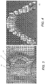
- Figure 3 shows surface imaging using a pattern with multiple lines of light. Incremental shifting of the line pattern and other techniques help to compensate for inaccuracies and confusion that can result from abrupt transitions along the surface, whereby it can be difficult to positively identify the segments that correspond to each projected line. In Figure 3 , for example, it can be difficult to determine whether line segment 16 is from the same line of illumination as line segment 18 or adjacent line segment 19.
- a computer and software can use triangulation methods to compute the coordinates of numerous illuminated surface points. As the plane is moved to intersect eventually with some or all of the surface of the object, the coordinates of an increasing number of points are accumulated. As a result of this image acquisition, a point cloud of vertex points or vertices can be identified and used to represent the extent of a surface within a volume.
- Figure 4 shows a dense point cloud 50 generated from a structured light imaging apparatus, CS 3500 3-D camera made by Carestream Heath, Inc., Rochester NY, USA, using results from patterned illumination such as that shown in Figure 3 .
- the point cloud 50 models physical location of sampled points on tooth surfaces and other intraoral surfaces or, more generally, of surfaces of a real-world object. Variable resolution can be obtained.
- the example of Fig. 4 shows an exemplary 100 micron resolution.
- the points in the point cloud represent actual, measured points on the three dimensional surface of an object.
- the surface structure can be approximated from the point cloud representation by forming a polygon mesh, in which adjacent vertices are connected by line segments. For a vertex, its adjacent vertices are those vertices closest to the vertex in terms of Euclidean distance.
- Figure 5 shows a 3-D polygon mesh model 60 in the simple form of a triangular mesh.
- a triangular mesh forms a basic mesh structure that can be generated from a point cloud and used as a digital model to represent a 3-D object by its approximate surface shape, in the form of triangular plane segments sharing adjacent boundaries.
- Methods/apparatus for forming a polygon mesh model such as a triangular mesh or more complex mesh structure, are well known to those skilled in the contour imaging arts.
- the polygon unit of the mesh model, and relationships between neighboring polygons, can be used in embodiments of the present disclosure to extract features (e.g., curvatures, minimum curvatures, edges, spatial relations, etc.) at the teeth boundaries.
- segmentation of individual components of the image content from a digital model can be of value to the dental practitioner in various procedures, including orthodontic treatment and preparation of crowns, implants, and other prosthetic devices, for example.
- Various methods have been proposed and demonstrated for mesh-based segmentation of teeth from gums and of teeth from each other.
- drawbacks of conventional segmentation solutions include requirements for a significant level of operator skill and a high degree of computational complexity.
- Conventional approaches to the problem of segmenting tooth components and other dentition features have yielded disappointing results in many cases.
- Exemplary method and/or apparatus embodiments address such problems with segmentation that can utilize the polygonal mesh data as a type of source digital model and can operate in more than one stage: e.g., first, performing an automated segmentation algorithm/procedures that can provide at least a close or coarse approximation of the needed segmentation of the digital model; and second, allowing operator interactions to improve, correct and/or clean up observed errors and inconsistencies in the automated results, which can yield highly accurate results that are difficult to achieve in a purely automated manner, but not placing significant requirements on operator time or skill level and/or on needed computer resources.
- This hybrid approach in exemplary method and/or apparatus embodiments can help to combine computing and image processing power with operator perception to check, correct, and refine results of automated processing.
- the logic flow diagram of Figure 6A shows a hybrid sequence for tooth mesh segmentation and generation of a digital model to identify individual features or intraoral components such as teeth from within the mouth according to an exemplary embodiment of the present disclosure.
- an image acquisition step S100 a plurality of structured light images of the patient's dentition are captured, providing a set of contour images for processing.
- a point cloud generation step S110 then generates a point cloud of the patient's dentition using the set of contour images.
- a polygon mesh generation step S120 forms a polygon mesh by connecting adjacent points from point cloud results.
- a triangular mesh provides one type of polygon mesh that can be readily generated for approximating a surface contour; more complex polygon mesh configurations can alternately be used.
- a segmentation step S130 can be executed.
- segmentation step S130 can distinguish teeth from gum tissue, as well as distinguishing one tooth from another. Segmentation results can then be displayed, showing the results of this initial, automated segmentation processing.
- the automated segmentation step S130 can provide an intermediate image.
- segmentation step S130 can perform the bulk of segmentation processing, but can further benefit from operator review and refinements of results.
- segmentation step S130 can use any of a number of known segmentation techniques, such as fast-marching watershed algorithms, so-called snake-based segmentation, and other methods known to those skilled in the imaging arts, as noted earlier.
- Figure 6A also shows an optional repeat loop that can enable viewer interaction with the intermediate image for refining the results of the automated segmentation processing, for example, using the basic apparatus shown in Figure 1 .
- An accept operator instructions step S140 can be executed, during which the viewer indicates, on the displayed results, seed points, seed lines, block lines, boundary features, or other markings that identify one or more distinct features of the segmentation results to allow further segmentation refinement and processing.
- Viewer markup instructions cause segmentation step S130 to be executed at least a second time, this second time using input markup(s) from entered viewer instructions. It can be appreciated that different segmentation algorithms can be applied at various stages of automated or manual processing. Final results of segmentation processing can be displayed, stored, and transmitted between computers, such as over a wired or wireless network, for example.
- tooth and gum partitioning can be automated.
- tooth and gum partitioning can use an automated curvature-based method that computes curvature of vertices in the mesh, and then uses a thresholding algorithm to identify margin vertices having large negative curvature.
- color-based segmentation can be used for tooth segmentation from the gums. This type of method can obtain average hue values from regions of the image and calculate threshold values that partition image content.
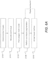
- FIG. 6B An exemplary embodiment of workflow for the hybrid tooth segmentation system is depicted in the logic flow diagram of Figure 6B .
- the control logic processor 80 ( Figure 1 ) initiates an automated segmentation step S202 in which a fully automatic tooth segmentation tool is evoked to delineate teeth and gum regions and delineate individual teeth regions.
- the fully automatic tooth segmentation tool employs exemplary algorithms such as active contour models published in the literature or otherwise well-known to those skilled in the image processing arts.
- the delineation of teeth effectively produces individually segmented teeth; however, these generated teeth may contain poorly segmented intraoral components.
- a first checking step S204 then checks for poorly segmented intraoral components.
- Checking for incorrect or incomplete segmentation in step S204 can be accomplished either computationally, such as by applying trained artificial intelligence algorithms to the segmentation results, or by viewer interaction, such as following visual inspection by the viewer.
- Figure 7A shows an exemplary poorly segmented or mis-segmented tooth 302. As shown in Figure 7A , a segmented tooth boundary 306 is not aligned with an actual tooth boundary 308.
- a primary assisted segmentation step S206 executes, activating a segmentation procedure that is also automated, but allows some level of operator adjustment.
- Primary assisted segmentation step S206 applies an algorithm for segmentation that allows operator adjustment of one or more parameters in a parameter adjustment step S210.
- Another checking step S208 executes to determine if additional segmentation processing is needed.
- the adjustable parameter can be altered computationally or explicitly by an operator instruction in step S210. Subsequent figures show an exemplary operator interface for parameter adjustment.
- An exemplary algorithm employed in primary assisted segmentation Step S206 can be a well-known technique, such as the mesh minimum curvature-based segmentation method.
- the adjustable parameter can be the threshold value of the curvature.
- the delineation of teeth performed in Step S206 may still produce poorly segmented intraoral components or features, so that a repeated segmentation process is helpful.
- the checking of poor segmentation in step S208 can be accomplished either computationally, such as by applying artificial intelligence algorithms to the segmentation results, or more directly, by visual inspection performed by the user.
- the hybrid tooth segmentation system optionally allows the user to add exemplary geometric primitives such as seed lines on the tooth region and add blocking lines between the teeth or between the teeth and gum to aid the tooth segmentation process.
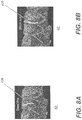
- Figure 8A shows an exemplary seed line 406 for marking a tooth, added to a mesh image 62.
- Figure 8B shows an exemplary block line 408 for indicating space between two teeth, added to a mesh image 62.
- Step S206, Step S208 and Step S210 in the Figure 6B sequence constitute an exemplary primary segmentation loop 54 that follows the fully automatic segmentation of step S202 and checking step S204.
- This exemplary primary segmentation loop 54 is intended to correct segmentation errors from the fully automated segmentation of automated segmentation step S202, as identified in step S204.
- Exemplary primary segmentation loop 54 can be executed one or more times, as needed. When exemplary primary segmentation loop 54 is successful, segmentation can be complete.
- an exemplary secondary segmentation loop 56 can be used to provide more interactive segmentation approaches.
- the secondary segmentation loop 56 can include an interactive segmentation step S212, another checking step S214, and an operator markup step S216.
- Interactive segmentation step S212 can activate a segmentation process that works with the operator for indicating areas of the image to be segmented from other areas.
- Interactive segmentation step S212 can have an automated sequence, implemented by an exemplary algorithm such as a "fast march" method known to those skilled in the image segmentation arts.
- Step S212 may require population of the tooth region images by operator-entered seeds or seed lines or other types of geometric primitives before activation or during processing.
- seed lines or other features can be automatically generated in Step S100, S110 and S120 when the dentition mesh is entered into the system for optional operator adjustment (e.g., subsequent operations such as secondary segmentation loop 56 or Step 212).
- the features, seeds or seed lines can be added to the segmentation process in operator markup Step S216 by the user.
- the results from Step S212 are subject to inspection by the user in Step S216. Results from the hybrid automated/interactive segmentation processing can then be displayed in a display step S220, as well as stored and transmitted to another computer.
- some exemplary methods/apparatus of the present disclosure provide a hybrid tooth segmentation that provides the benefits of interactive segmentation with human-machine synergy.
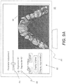
- FIGS 9A-9C show operator interface screens 52 for portions of a sequence for review and entry of markup instructions for refining mesh segmentation processing according to certain exemplary embodiments of the present disclosure.
- Interim mesh segmentation results are shown in a display area 86 on screen 52.
- a number of controls 90 for adjustment of the segmentation process are available, such as an adjustment control 84 for setting a level for overall aggressiveness or other parameter or characteristic of the segmentation processing algorithm.
- Optional selection controls 88 allow the viewer to specify one or more segmentation algorithms to be applied. This gives the operator an opportunity to assess whether one particular type of segmentation algorithm or another appear to be more successful in performing the segmentation task for the given mesh digital model. The operator can compare results against the original and adjust parameters to view results of successive segmentation attempts, with and without operator markup.
- Figure 9A also shows a trace pattern 96 that is entered as an operator seed line instruction for correcting or refining segmentation processing, as was shown previously with respect to Figure 8A .
- an operator mark in the form of trace pattern 96 or other arbitrary marking/geometric can be used to provide seed points that indicate a specific feature for segmentation, such as a molar or other tooth feature that may be difficult to process for conventional segmentation routines. Seed marks can then be used as input to a fast marching algorithm or other algorithm type, as described previously. In some cases, for example, adjacent teeth may not be accurately segmented with respect to each other; operator markup can provide useful guidance for segmentation processing where standard segmentation logic does not perform well.
- the operator can have controls 90 available that allow the entered markup to be cleared or provided to the segmentation processor.
- controls 90 color or shading can be used to differentiate various teeth or other structures identified by segmentation. Additional controls 90 can also be used to display individual segmented elements, such as individual teeth, for example.
- individual controls 90 can be used individually or in combination.
- segmentation of individual teeth from each other can use curvature thresholds to compute margin and border vertices, then use various growth techniques to define the bounds of each tooth relative to margin detection.
- controls 90 can include, but are not limited to enter/adjust seed or boundary geometries, enter/adjust selected segmentation procedures, enter/adjust number of objects to segment, subdivide selected object, modify segmented object display, etc.
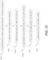
- FIG. 10 shows an exemplary embodiment of a workflow for bracket removal from a dentition 3D mesh according to the application.
- a virtual or digital 3D dentition mesh model is obtained in step 1002.
- a digital 3D dentition mesh model can be obtained by using an intraoral scanner.
- Figure 11 is a diagram that shows an exemplary 3D dentition mesh that can be acquired in step 1002.
- 3D dentition mesh 1100 can include brackets 1102, gingival 1104 and teeth 1106.
- a result from the exemplary workflow process of Figure 10 will be a 3D dentition mesh including the teeth 1106 and gingival 1104 from the 3D dentition mesh 1100, but without the brackets 1102 and tooth surfaces previously covered by brackets 1102 accurately re-constructed.
- steps 1004 and 1006 constitute a tooth segmentation method/system for an obtained dentition 3D mesh.
- steps 1004 and 1006 can be implemented by similar steps of a hybrid sequence for tooth mesh segmentation depicted in Figure 6A .
- steps 1004 and 1006 can be implemented by similar steps of a hybrid tooth segmentation method/system depicted in Figure 6B .
- brackets 1102 are automatically removed from the 3D dentition mesh 1100 (e.g., tooth surfaces) in step 1008.
- the separated (or segmented) teeth resulting from step 1006 can individually undergo bracket removal and surface reconstruction described hereafter.
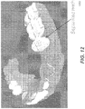
- Figure 12 is a diagram that shows exemplary resultant separated teeth 1202 contained within the 3D dentition mesh 1100.
- each individually segmented tooth (or crown) is examined and processed.
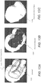
- An exemplary segmented tooth 1202 with bracket 1302 to be removed is shown in Figure 13A .
- an automatic bracket removal algorithm first detects boundaries of the bracket 1302.
- bracket boundary detection can use an automated curvature-based algorithm that computes the curvatures of vertices in the mesh of tooth surfaces, and then uses a thresholding algorithm to identify margin vertices that have large negative curvatures.
- FIG. 13A is a diagram that shows an exemplary segmented tooth 1202 with bracket 1302 removed.
- FIG. 13B small white patches can be present in the bracket hole 1304; these white patches do not belong to the bracket 1302 itself, but can be other artifacts behind the original bracket. These artifacts can become visible after the bracket 1302 has been removed from the 3D dentition mesh 100 by an automatic bracket removal algorithm.
- step 1010 tooth surfaces of the segmented tooth 1202 having the bracket removed are automatically reconstructed.
- Various approaches known to one skilled in the imaging arts can be used to fill holes in the 3D dentition mesh 1100.
- An exemplary segmented tooth 1202 having automatically reconstructed tooth surface 1306 is shown in Figure 13C .
- hole-filling procedures e.g., tooth or crown surface reconstruction
- Figure 13D shows a part of the 3D dentition mesh 1100 forming a 3D crown mesh surface after mesh portions representing a bracket are removed.
- a closed polygon 1303' represents a boundary of the (removed) bracket.
- a region 1308 enclosed by the closed polygon 1303' is the hole left by bracket removal.
- an initial patch is generated to fill the tooth surface or hole 1308 (e.g., within the closed polygon 1303').
- the initial patch contains a plurality of triangles 1310 arranged in an exemplary prescribed pattern such as one formed by connecting vertices in the closed polygon 1303' to form the pattern shown in Figure 13E .
- triangles/polygons 1310 of the initial patch can be further modified or optimized.
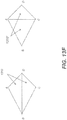
- One exemplary procedure of modifying or optimally arranging the triangles 1310 is illustrated in Figure 13F where four points A, B, C, and D form two triangles ABD and CDB in the triangles 1310, which are rearranged to become triangles ABC and CDA in an improved set of triangles 1310'.
- An improved triangle arrangement can reduce or avoid long, thin triangles.
- the 3D mesh with the initial patch can be smoothed to obtain better quality.
- the second part of step 1010 can correct positions of points created in the initial patch using local information globally.
- the 3D mesh including the initial patch e.g., triangles 1310, 1310' within the hole 1303'
- the surrounding regions such as triangles 1312 surrounding (or nearby) the hole 1308' in Figure 13D
- the 3D mesh including the initial patch can be smoothed using a Laplacian smoothing method that adjusts the location of each mesh vertex to the geometric center of its neighbor vertices.
- step 1012 the exemplary segmented tooth 1202 having automatically reconstructed tooth surface 1306 (see Figure 13C ) can be displayed.
- steps 1008, 1010 and 1012 can be repeatedly performed until all brackets are removed from 3D dentition mesh 1100.
- the resultant corrected 3D dentition mesh 1100 can be displayed in step 1012 after each additional segmented tooth surface is corrected.
- steps 1008 and 1010 can be performed for all teeth in the 3D dentition mesh 1100, before the resultant corrected 3D dentition mesh 1100 is displayed in step 1012.
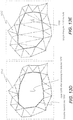
- Figure 20 shown an exemplary entire resultant corrected 3D dentition mesh.
- Certain exemplary method and/or apparatus embodiments can use alternative procedures to reconstruct the teeth surfaces.
- a 3D detention mesh from an intra-oral scan of the dentition before the braces were attached can be used in tooth surface reconstruction.
- models of specific teeth taken from sets of full mouth tooth models for varying ages, dental arch sizes, ethnicity, sex, of the patient can be used in tooth surface reconstruction.
- corresponding "mirror" teeth form the patient can be used.
- Figure 14 is a diagram that shows a workflow of another exemplary embodiment of the present invention of bracket removal on a 3D dentition mesh.
- a primary difference between the workflow shown in Figure 10 and the workflow shown in Figure 14 is that teeth segmentation is not required in workflow presented in Figure 14 .
- a 3D dentition mesh is received in step 1402 that contains teeth, brackets, and gingival.
- instructions are received from an operator regarding brackets in the 3D dentition mesh.
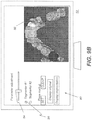
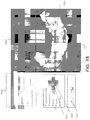
- Figure 15 is a diagram that displays an exemplary GUI interface that allows the user to input information to identify brackets in the 3D dentition mesh.
- one exemplary GUI interface 1500 enables nodes to be placed by the user for a 'snake' operation, which automatically encircles bracket 1502 boundaries, based on the entered nodes.
- An exemplary bracket boundary 1503 generated by the 'snake' operation is shown in Figure 15 .
- the 'snake' is an active shape model that is frequently used in automatic object segmentation in image processing, for example by delineating an object outline from a possibly noisy 2D image.
- the snakes active shape model is used in applications like object tracking, shape recognition, segmentation, edge detection and stereo matching.
- the snake active shape model or active contour model is known to one skilled in the imaging arts.
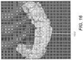
- Figure 16 shows vertices 1602 encircled by the boundary 1503 being highlighted in the 3D dentition mesh after the user pressed the 'run' button 1504 in Figure 15 .
- Identified vertices 1602 are to be removed from the original 3D dentition mesh.
- the GUI system 1500 can let the user inspect the intermediate results 1602, and if satisfied, the user presses the 'cut' button 1506, then the vertices 1602 change their highlight (e.g., color, texture, etc.) to indicate that these vertices are to be removed from the original 3D dentition mesh.
- to automatically remove the brackets from the teeth surface based on the operator instructions in step 1406 can be performed by the operator pressing the 'cut' button 1506.
- step 1408 is performed when the user presses the 'fill' button 1508 in Figure 15 to reconstruct tooth surfaces.
- Step 1408 can be performed using known algorithms such as described herein with respect to Figure 10 .
- the results can be displayed for inspection in step 1410.
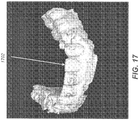
- Figure 17 shows an example of a reconstructed tooth surface 1702 after the bracket is removed.
- the results of step 1408 could be stored or transmitted over a network to a remote computer for use.
- Figure 14 the operations can be performed tooth by tooth, on a plurality of teeth or all teeth simultaneously at a time with respect to the 3D dentition mesh.
- Figures 18-20 are diagrams that show a complete removal of all brackets concurrently from a 3D jaw mesh.
- Figure 18 is a diagram that shows a 3D dentition mesh 1800 with teeth, brackets and gingival.
- Figure 19 is a diagram that shows the intermediate results of 'snake' cut operation with vertices 1802 that are to be removed being highlighted.
- Figure 20 is a diagram that shows each of the final reconstructed teeth surfaces 1806 after all brackets are removed and all fill operations are completed.
- FIG. 21A is a diagram that shows another exemplary dentition model.
- dentition model 2100 includes brackets 2102, gingival 2104, teeth 2106 and bridged brackets where a wire 2108 connects at least bracket 2110 and bracket 2112.
- wires 2108 s will connect all brackets 2102.
- the wire 2108 can erased either automatically or interactively according to certain exemplary method and/or apparatus embodiments of the application.
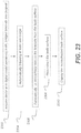
- FIG. 23 is a logic flow diagram that shows an exemplary sequence for bridged bracket removal from tooth mesh surfaces according to an embodiment of the application. As shown in Figure 23 , a dentition model with bridged brackets is obtained in step 2302, which is immediately followed by step 2304 that includes "automatically breaking the bridge".
- step 2302 a dentition model with bridged brackets is obtained in step 2302, which is immediately followed by step 2304 that includes "automatically breaking the bridge".
- step 2304 that includes "automatically breaking the bridge”.
- One exemplary detection embodiment that can be used to automatically break the bridge (or wire) is described as follows.
- V Given a vertex V in the dentition mesh modal, perform a nearest neighbor search with an exemplary 5mm radius resulting in a set of neighbor vertices VN. Check the normal of each of the vertices in VN. If it is found that there is at least one vertex in VN whose normal points to the opposite direction of the normal of V (e.g. if these two normal vectors' dot product ⁇ -0.9), then V is a candidate vertex on the wire (or bridge). This procedure is applied to the entire mesh resulting in a plurality of candidate vertices. Said candidate vertices are used to compute a plurality of connected regions.
- Each of said connected regions is analyzed using the algorithm of principal component analysis commonly used by people skilled in the art for shape (e.g. wire) detection.
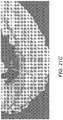
- An exemplary bridge (wire) detection result 2118 resulting from step 2306 is shown in Figure 21C .
- These vertices of the 3D detention mesh detected in step 2306 (e.g., associated with the wires 2108) are excluded or removed from the 3D detention mesh in the subsequent steps 2306-2308.
- Step 2306 employs either exemplary automatic or interactive methods to remove the disconnected brackets.
- the bracket removed tooth surface is reconstructed automatically in step 2308 and the results are displayed for inspection in Step 2310.
- steps 2306 and 2308 can be performed as described above for Figures 10 and 14 , respectively.
- FIG 22 an actual result 2204 for bridged brackets removal is shown.
- the surface reconstructed tooth 2210 and tooth 2212 in Figure 22 correspond to bracket 2110 and bracket 2112 in Figure 21A before the brackets and wire 2108 are removed.
- Figure 24 is a logic flow chart that shows another exemplary method embodiment dealing with bridged brackets removal.
- a dentition model with bridged brackets is acquired in step 2402, which is immediately followed by a step 2404 of "interactively breaking said bridge".
- interactive operation effectively erases the thin wires with the assistance from a human by selecting and deleting mesh vertices that belong to the thin wires in step 2404.
- step 2404 can use a GUI with selectable operator actions to "clear”, "paint” (e.g., operator identify pixels showing wires), "auto paint”, “approve” (e.g., paint or auto paint), and “clear” to interactively break the bridges or remove the wires from the 3D dentition mesh based on the operator instructions.
- step 2406 employs either automatic or interactive method to remove the disconnected brackets as previously described.
- the bracket removed tooth surfaces can be reconstructed automatically in step 2408 as previously described. Then, the results are displayed for inspection in step 2410.
- bridged brackets can be removed and teeth surfaces restored by automatically identifying parts of a bracket and/or wire without human intervention in an obtained 3D dentition model by growing the identified parts into a region that covers the brackets and/or wires entirely (e.g., and preferably slightly beyond the brackets and/or wires boundaries). removing the region from the 3D dentition model surface, and restoring the removed region surfaces using hole filling techniques.
- hole filling can fill portions of gingival.
- the present disclosure can use a computer program with stored instructions that control system functions for image acquisition and image data processing for image data that is stored and accessed from an electronic memory.
- a computer program of an embodiment of the present invention can be utilized by a suitable, general-purpose computer system, such as a personal computer or workstation that acts as an image processor, when provided with a suitable software program so that the processor operates to acquire, process, transmit, store, and display data as described herein.
- a suitable, general-purpose computer system such as a personal computer or workstation that acts as an image processor
- a suitable software program so that the processor operates to acquire, process, transmit, store, and display data as described herein.
- Many other types of computer systems architectures can be used to execute the computer program of the present invention, including an arrangement of networked processors, for example.
- the computer program for performing the method of the present invention may be stored in a computer readable storage medium.
- This medium may comprise, for example; magnetic storage media such as a magnetic disk such as a hard drive or removable device or magnetic tape; optical storage media such as an optical disc, optical tape, or machine readable optical encoding; solid state electronic storage devices such as random access memory (RAM), or read only memory (ROM); or any other physical device or medium employed to store a computer program.
- the computer program for performing the method of the present invention may also be stored on computer readable storage medium that is connected to the image processor by way of the internet or other network or communication medium. Those skilled in the image data processing arts will further readily recognize that the equivalent of such a computer program product may also be constructed in hardware.
- memory can refer to any type of temporary or more enduring data storage workspace used for storing and operating upon image data and accessible to a computer system, including a database.
- the memory could be non-volatile, using, for example, a long-term storage medium such as magnetic or optical storage. Alternately, the memory could be of a more volatile nature, using an electronic circuit, such as random-access memory (RAM) that is used as a temporary buffer or workspace by a microprocessor or other control logic processor device.
- Display data for example, is typically stored in a temporary storage buffer that is directly associated with a display device and is periodically refreshed as needed in order to provide displayed data.
- This temporary storage buffer can also be considered to be a memory, as the term is used in the present disclosure.
- Memory is also used as the data workspace for executing and storing intermediate and final results of calculations and other processing.
- Computer-accessible memory can be volatile, non-volatile, or a hybrid combination of volatile and non-volatile types.
- the computer program product of the present disclosure may make use of various image manipulation algorithms and processes that are well known. It will be further understood that the computer program product embodiment of the present invention may embody algorithms and processes not specifically shown or described herein that are useful for implementation. Such algorithms and processes may include conventional utilities that are within the ordinary skill of the image processing arts. Additional aspects of such algorithms and systems, and hardware and/or software for producing and otherwise processing the images or co-operating with the computer program product of the present invention, are not specifically shown or described herein and may be selected from such algorithms, systems, hardware, components and elements known in the art.
- Exemplary embodiments according to the application can include various features described herein (individually or in combination).
Landscapes
- Health & Medical Sciences (AREA)
- Life Sciences & Earth Sciences (AREA)
- Oral & Maxillofacial Surgery (AREA)
- Dentistry (AREA)
- Animal Behavior & Ethology (AREA)
- General Health & Medical Sciences (AREA)
- Public Health (AREA)
- Veterinary Medicine (AREA)
- Epidemiology (AREA)
- Engineering & Computer Science (AREA)
- Physics & Mathematics (AREA)
- Optics & Photonics (AREA)
- General Engineering & Computer Science (AREA)
- Audiology, Speech & Language Pathology (AREA)
- Biophysics (AREA)
- Pathology (AREA)
- Biomedical Technology (AREA)
- Heart & Thoracic Surgery (AREA)
- Medical Informatics (AREA)
- Molecular Biology (AREA)
- Surgery (AREA)
- Dental Tools And Instruments Or Auxiliary Dental Instruments (AREA)
Applications Claiming Priority (1)
| Application Number | Priority Date | Filing Date | Title |
|---|---|---|---|
| PCT/US2016/044399 WO2018022054A1 (en) | 2016-07-28 | 2016-07-28 | Method and system for dentition mesh braces removal |
Publications (2)
| Publication Number | Publication Date |
|---|---|
| EP3490489A1 EP3490489A1 (en) | 2019-06-05 |
| EP3490489B1 true EP3490489B1 (en) | 2021-02-24 |
Family
ID=56609997
Family Applications (1)
| Application Number | Title | Priority Date | Filing Date |
|---|---|---|---|
| EP16747994.8A Active EP3490489B1 (en) | 2016-07-28 | 2016-07-28 | Method and system for removing orthodontic brackets from the digital mesh of the dentition |
Country Status (7)
| Country | Link |
|---|---|
| US (1) | US11058514B2 (enExample) |
| EP (1) | EP3490489B1 (enExample) |
| JP (2) | JP2019521811A (enExample) |
| KR (1) | KR20190037241A (enExample) |
| DK (1) | DK3490489T3 (enExample) |
| ES (1) | ES2864684T3 (enExample) |
| WO (1) | WO2018022054A1 (enExample) |
Families Citing this family (25)
| Publication number | Priority date | Publication date | Assignee | Title |
|---|---|---|---|---|
| EP3471617B1 (en) * | 2016-06-17 | 2023-09-27 | Carestream Dental Technology Topco Limited | Method and system for 3d cephalometric analysis |
| US11559378B2 (en) | 2016-11-17 | 2023-01-24 | James R. Glidewell Dental Ceramics, Inc. | Scanning dental impressions |
| KR20190087593A (ko) * | 2016-11-30 | 2019-07-24 | 케어스트림 덴탈 테크놀로지 톱코 리미티드 | 치열 메시로부터 브레이스 제거를 위한 방법 및 시스템 |
| WO2018170030A1 (en) | 2017-03-16 | 2018-09-20 | Carestream Dental Technology Topco Limited | Method for virtual setup with mixed dentition |
| US11212506B2 (en) | 2018-07-31 | 2021-12-28 | Intel Corporation | Reduced rendering of six-degree of freedom video |
| US11178373B2 (en) | 2018-07-31 | 2021-11-16 | Intel Corporation | Adaptive resolution of point cloud and viewpoint prediction for video streaming in computing environments |
| US10887574B2 (en) | 2018-07-31 | 2021-01-05 | Intel Corporation | Selective packing of patches for immersive video |
| US10911799B2 (en) * | 2018-07-31 | 2021-02-02 | Intel Corporation | Video refinement mechanism |
| US10762394B2 (en) | 2018-07-31 | 2020-09-01 | Intel Corporation | System and method for 3D blob classification and transmission |
| US10893299B2 (en) | 2018-07-31 | 2021-01-12 | Intel Corporation | Surface normal vector processing mechanism |
| DE102019127349A1 (de) | 2018-10-10 | 2020-04-16 | Intel Corporation | Punktwolkencodierungsstandard-konformitätsdefintion in computerumgebungen |
| US11057631B2 (en) | 2018-10-10 | 2021-07-06 | Intel Corporation | Point cloud coding standard conformance definition in computing environments |
| CN110211170B (zh) * | 2019-05-23 | 2021-04-09 | 南京维拓科技股份有限公司 | 一种基于数字化模型壁厚分析方法 |
| US11986325B2 (en) * | 2019-06-13 | 2024-05-21 | Osstemimplant Co., Ltd. | Treatment information display device and method for displaying treatment history on image of teeth in accumulated manner |
| US11540906B2 (en) | 2019-06-25 | 2023-01-03 | James R. Glidewell Dental Ceramics, Inc. | Processing digital dental impression |
| US11622843B2 (en) | 2019-06-25 | 2023-04-11 | James R. Glidewell Dental Ceramics, Inc. | Processing digital dental impression |
| US11534271B2 (en) | 2019-06-25 | 2022-12-27 | James R. Glidewell Dental Ceramics, Inc. | Processing CT scan of dental impression |
| US11957974B2 (en) | 2020-02-10 | 2024-04-16 | Intel Corporation | System architecture for cloud gaming |
| US11760029B2 (en) * | 2020-06-23 | 2023-09-19 | Continuous Composites Inc. | Systems and methods for controlling additive manufacturing |
| US11544846B2 (en) | 2020-08-27 | 2023-01-03 | James R. Glidewell Dental Ceramics, Inc. | Out-of-view CT scan detection |
| KR102460621B1 (ko) * | 2020-09-23 | 2022-10-28 | 주식회사 메디트 | 구강 이미지 처리 장치, 및 구강 이미지 처리 방법 |
| US11475544B2 (en) * | 2020-10-16 | 2022-10-18 | Adobe Inc. | Automated braces removal from images |
| WO2022129994A1 (en) | 2020-12-16 | 2022-06-23 | Arcelormittal | Coated steel sheet and high strength press hardened steel part and method of manufacturing the same |
| KR102718586B1 (ko) * | 2021-03-19 | 2024-10-17 | 주식회사 메디트 | 구강 스캔 데이터 표시 시스템 |
| US12387338B2 (en) * | 2021-06-15 | 2025-08-12 | Imagoworks Inc. | Method for automated tooth segmentation of three dimensional scan data using deep learning and computer readable medium having program for performing the method |
Family Cites Families (9)
| Publication number | Priority date | Publication date | Assignee | Title |
|---|---|---|---|---|
| JP3641208B2 (ja) * | 1998-10-08 | 2005-04-20 | アライン テクノロジー, インコーポレイテッド | コンピュータで自動化された歯列処置計画および器具の開発 |
| US7004754B2 (en) * | 2003-07-23 | 2006-02-28 | Orametrix, Inc. | Automatic crown and gingiva detection from three-dimensional virtual model of teeth |
| US7473097B2 (en) * | 2004-12-17 | 2009-01-06 | 3M Innovative Properties Company | RFID tracking of patient-specific orthodontic materials |
| US7372642B2 (en) * | 2006-02-13 | 2008-05-13 | 3M Innovative Properties Company | Three-channel camera systems with non-collinear apertures |
| JP2011507615A (ja) * | 2007-12-21 | 2011-03-10 | スリーエム イノベイティブ プロパティズ カンパニー | 仮想歯列モデルの作成方法とそれを用いた歯列矯正リテーナーの製作方法 |
| US20140067334A1 (en) * | 2012-09-06 | 2014-03-06 | Align Technology Inc. | Method and a system usable in creating a subsequent dental appliance |
| EP2837356A1 (en) * | 2013-08-14 | 2015-02-18 | 3M Innovative Properties Company | An orthodontic bracket and a method of making an orthodontic bracket |
| KR101618233B1 (ko) * | 2014-05-22 | 2016-05-04 | 조선대학교산학협력단 | 맞춤형 치열 교정 장치의 제조방법 및 이에 의해 제조된 맞춤형 치열 교정 장치 |
| US9626462B2 (en) * | 2014-07-01 | 2017-04-18 | 3M Innovative Properties Company | Detecting tooth wear using intra-oral 3D scans |
-
2016
- 2016-07-28 KR KR1020197002635A patent/KR20190037241A/ko not_active Withdrawn
- 2016-07-28 US US16/321,370 patent/US11058514B2/en active Active
- 2016-07-28 JP JP2019504714A patent/JP2019521811A/ja active Pending
- 2016-07-28 ES ES16747994T patent/ES2864684T3/es active Active
- 2016-07-28 EP EP16747994.8A patent/EP3490489B1/en active Active
- 2016-07-28 WO PCT/US2016/044399 patent/WO2018022054A1/en not_active Ceased
- 2016-07-28 DK DK16747994.8T patent/DK3490489T3/da active
-
2021
- 2021-09-27 JP JP2021156322A patent/JP7386215B2/ja active Active
Non-Patent Citations (1)
| Title |
|---|
| None * |
Also Published As
| Publication number | Publication date |
|---|---|
| US20190159868A1 (en) | 2019-05-30 |
| WO2018022054A8 (en) | 2019-01-31 |
| ES2864684T3 (es) | 2021-10-14 |
| JP7386215B2 (ja) | 2023-11-24 |
| US11058514B2 (en) | 2021-07-13 |
| DK3490489T3 (da) | 2021-04-19 |
| JP2019521811A (ja) | 2019-08-08 |
| EP3490489A1 (en) | 2019-06-05 |
| WO2018022054A1 (en) | 2018-02-01 |
| KR20190037241A (ko) | 2019-04-05 |
| JP2022000211A (ja) | 2022-01-04 |
Similar Documents
| Publication | Publication Date | Title |
|---|---|---|
| US11896455B2 (en) | Method and system for braces removal from dentition mesh | |
| JP7386215B2 (ja) | 歯列メッシュ矯正具除去のための方法および装置 | |
| JP7289026B2 (ja) | ハイブリッドメッシュセグメンテーションのための方法及び装置 | |
| EP3346943B1 (en) | Method and system for hybrid mesh segmentation | |
| US11961238B2 (en) | Tooth segmentation using tooth registration | |
| US20220012888A1 (en) | Methods and system for autonomous volumetric dental image segmentation | |
| US20220068039A1 (en) | 3d segmentation for mandible and maxilla | |
| US12056836B2 (en) | Dental model superimposition using clinical indications | |
| EP3185813B1 (en) | Method for dental virtual model base | |
| WO2020037582A1 (en) | Graph-based key frame selection for 3-d scanning |
Legal Events
| Date | Code | Title | Description |
|---|---|---|---|
| STAA | Information on the status of an ep patent application or granted ep patent |
Free format text: STATUS: THE INTERNATIONAL PUBLICATION HAS BEEN MADE |
|
| PUAI | Public reference made under article 153(3) epc to a published international application that has entered the european phase |
Free format text: ORIGINAL CODE: 0009012 |
|
| STAA | Information on the status of an ep patent application or granted ep patent |
Free format text: STATUS: REQUEST FOR EXAMINATION WAS MADE |
|
| 17P | Request for examination filed |
Effective date: 20190128 |
|
| AK | Designated contracting states |
Kind code of ref document: A1 Designated state(s): AL AT BE BG CH CY CZ DE DK EE ES FI FR GB GR HR HU IE IS IT LI LT LU LV MC MK MT NL NO PL PT RO RS SE SI SK SM TR |
|
| AX | Request for extension of the european patent |
Extension state: BA ME |
|
| DAV | Request for validation of the european patent (deleted) | ||
| DAX | Request for extension of the european patent (deleted) | ||
| STAA | Information on the status of an ep patent application or granted ep patent |
Free format text: STATUS: EXAMINATION IS IN PROGRESS |
|
| 17Q | First examination report despatched |
Effective date: 20200214 |
|
| GRAP | Despatch of communication of intention to grant a patent |
Free format text: ORIGINAL CODE: EPIDOSNIGR1 |
|
| STAA | Information on the status of an ep patent application or granted ep patent |
Free format text: STATUS: GRANT OF PATENT IS INTENDED |
|
| GRAJ | Information related to disapproval of communication of intention to grant by the applicant or resumption of examination proceedings by the epo deleted |
Free format text: ORIGINAL CODE: EPIDOSDIGR1 |
|
| GRAP | Despatch of communication of intention to grant a patent |
Free format text: ORIGINAL CODE: EPIDOSNIGR1 |
|
| INTG | Intention to grant announced |
Effective date: 20200924 |
|
| INTG | Intention to grant announced |
Effective date: 20201014 |
|
| GRAS | Grant fee paid |
Free format text: ORIGINAL CODE: EPIDOSNIGR3 |
|
| GRAA | (expected) grant |
Free format text: ORIGINAL CODE: 0009210 |
|
| STAA | Information on the status of an ep patent application or granted ep patent |
Free format text: STATUS: THE PATENT HAS BEEN GRANTED |
|
| AK | Designated contracting states |
Kind code of ref document: B1 Designated state(s): AL AT BE BG CH CY CZ DE DK EE ES FI FR GB GR HR HU IE IS IT LI LT LU LV MC MK MT NL NO PL PT RO RS SE SI SK SM TR |
|
| REG | Reference to a national code |
Ref country code: CH Ref legal event code: EP |
|
| REG | Reference to a national code |
Ref country code: AT Ref legal event code: REF Ref document number: 1363528 Country of ref document: AT Kind code of ref document: T Effective date: 20210315 |
|
| REG | Reference to a national code |
Ref country code: IE Ref legal event code: FG4D |
|
| REG | Reference to a national code |
Ref country code: DE Ref legal event code: R096 Ref document number: 602016053117 Country of ref document: DE |
|
| REG | Reference to a national code |
Ref country code: DK Ref legal event code: T3 Effective date: 20210415 |
|
| REG | Reference to a national code |
Ref country code: FI Ref legal event code: FGE |
|
| REG | Reference to a national code |
Ref country code: LT Ref legal event code: MG9D |
|
| REG | Reference to a national code |
Ref country code: NL Ref legal event code: MP Effective date: 20210224 |
|
| PG25 | Lapsed in a contracting state [announced via postgrant information from national office to epo] |
Ref country code: HR Free format text: LAPSE BECAUSE OF FAILURE TO SUBMIT A TRANSLATION OF THE DESCRIPTION OR TO PAY THE FEE WITHIN THE PRESCRIBED TIME-LIMIT Effective date: 20210224 Ref country code: GR Free format text: LAPSE BECAUSE OF FAILURE TO SUBMIT A TRANSLATION OF THE DESCRIPTION OR TO PAY THE FEE WITHIN THE PRESCRIBED TIME-LIMIT Effective date: 20210525 Ref country code: NO Free format text: LAPSE BECAUSE OF FAILURE TO SUBMIT A TRANSLATION OF THE DESCRIPTION OR TO PAY THE FEE WITHIN THE PRESCRIBED TIME-LIMIT Effective date: 20210524 Ref country code: PT Free format text: LAPSE BECAUSE OF FAILURE TO SUBMIT A TRANSLATION OF THE DESCRIPTION OR TO PAY THE FEE WITHIN THE PRESCRIBED TIME-LIMIT Effective date: 20210624 Ref country code: BG Free format text: LAPSE BECAUSE OF FAILURE TO SUBMIT A TRANSLATION OF THE DESCRIPTION OR TO PAY THE FEE WITHIN THE PRESCRIBED TIME-LIMIT Effective date: 20210524 Ref country code: LT Free format text: LAPSE BECAUSE OF FAILURE TO SUBMIT A TRANSLATION OF THE DESCRIPTION OR TO PAY THE FEE WITHIN THE PRESCRIBED TIME-LIMIT Effective date: 20210224 |
|
| REG | Reference to a national code |
Ref country code: AT Ref legal event code: MK05 Ref document number: 1363528 Country of ref document: AT Kind code of ref document: T Effective date: 20210224 |
|
| PG25 | Lapsed in a contracting state [announced via postgrant information from national office to epo] |
Ref country code: SE Free format text: LAPSE BECAUSE OF FAILURE TO SUBMIT A TRANSLATION OF THE DESCRIPTION OR TO PAY THE FEE WITHIN THE PRESCRIBED TIME-LIMIT Effective date: 20210224 Ref country code: RS Free format text: LAPSE BECAUSE OF FAILURE TO SUBMIT A TRANSLATION OF THE DESCRIPTION OR TO PAY THE FEE WITHIN THE PRESCRIBED TIME-LIMIT Effective date: 20210224 Ref country code: PL Free format text: LAPSE BECAUSE OF FAILURE TO SUBMIT A TRANSLATION OF THE DESCRIPTION OR TO PAY THE FEE WITHIN THE PRESCRIBED TIME-LIMIT Effective date: 20210224 Ref country code: LV Free format text: LAPSE BECAUSE OF FAILURE TO SUBMIT A TRANSLATION OF THE DESCRIPTION OR TO PAY THE FEE WITHIN THE PRESCRIBED TIME-LIMIT Effective date: 20210224 Ref country code: NL Free format text: LAPSE BECAUSE OF FAILURE TO SUBMIT A TRANSLATION OF THE DESCRIPTION OR TO PAY THE FEE WITHIN THE PRESCRIBED TIME-LIMIT Effective date: 20210224 |
|
| PG25 | Lapsed in a contracting state [announced via postgrant information from national office to epo] |
Ref country code: IS Free format text: LAPSE BECAUSE OF FAILURE TO SUBMIT A TRANSLATION OF THE DESCRIPTION OR TO PAY THE FEE WITHIN THE PRESCRIBED TIME-LIMIT Effective date: 20210624 |
|
| REG | Reference to a national code |
Ref country code: ES Ref legal event code: FG2A Ref document number: 2864684 Country of ref document: ES Kind code of ref document: T3 Effective date: 20211014 |
|
| PG25 | Lapsed in a contracting state [announced via postgrant information from national office to epo] |
Ref country code: SM Free format text: LAPSE BECAUSE OF FAILURE TO SUBMIT A TRANSLATION OF THE DESCRIPTION OR TO PAY THE FEE WITHIN THE PRESCRIBED TIME-LIMIT Effective date: 20210224 Ref country code: AT Free format text: LAPSE BECAUSE OF FAILURE TO SUBMIT A TRANSLATION OF THE DESCRIPTION OR TO PAY THE FEE WITHIN THE PRESCRIBED TIME-LIMIT Effective date: 20210224 Ref country code: EE Free format text: LAPSE BECAUSE OF FAILURE TO SUBMIT A TRANSLATION OF THE DESCRIPTION OR TO PAY THE FEE WITHIN THE PRESCRIBED TIME-LIMIT Effective date: 20210224 Ref country code: CZ Free format text: LAPSE BECAUSE OF FAILURE TO SUBMIT A TRANSLATION OF THE DESCRIPTION OR TO PAY THE FEE WITHIN THE PRESCRIBED TIME-LIMIT Effective date: 20210224 |
|
| REG | Reference to a national code |
Ref country code: DE Ref legal event code: R097 Ref document number: 602016053117 Country of ref document: DE |
|
| PG25 | Lapsed in a contracting state [announced via postgrant information from national office to epo] |
Ref country code: SK Free format text: LAPSE BECAUSE OF FAILURE TO SUBMIT A TRANSLATION OF THE DESCRIPTION OR TO PAY THE FEE WITHIN THE PRESCRIBED TIME-LIMIT Effective date: 20210224 Ref country code: RO Free format text: LAPSE BECAUSE OF FAILURE TO SUBMIT A TRANSLATION OF THE DESCRIPTION OR TO PAY THE FEE WITHIN THE PRESCRIBED TIME-LIMIT Effective date: 20210224 |
|
| PLBE | No opposition filed within time limit |
Free format text: ORIGINAL CODE: 0009261 |
|
| STAA | Information on the status of an ep patent application or granted ep patent |
Free format text: STATUS: NO OPPOSITION FILED WITHIN TIME LIMIT |
|
| PG25 | Lapsed in a contracting state [announced via postgrant information from national office to epo] |
Ref country code: AL Free format text: LAPSE BECAUSE OF FAILURE TO SUBMIT A TRANSLATION OF THE DESCRIPTION OR TO PAY THE FEE WITHIN THE PRESCRIBED TIME-LIMIT Effective date: 20210224 |
|
| 26N | No opposition filed |
Effective date: 20211125 |
|
| PG25 | Lapsed in a contracting state [announced via postgrant information from national office to epo] |
Ref country code: SI Free format text: LAPSE BECAUSE OF FAILURE TO SUBMIT A TRANSLATION OF THE DESCRIPTION OR TO PAY THE FEE WITHIN THE PRESCRIBED TIME-LIMIT Effective date: 20210224 |
|
| REG | Reference to a national code |
Ref country code: CH Ref legal event code: PL |
|
| PG25 | Lapsed in a contracting state [announced via postgrant information from national office to epo] |
Ref country code: MC Free format text: LAPSE BECAUSE OF FAILURE TO SUBMIT A TRANSLATION OF THE DESCRIPTION OR TO PAY THE FEE WITHIN THE PRESCRIBED TIME-LIMIT Effective date: 20210224 |
|
| REG | Reference to a national code |
Ref country code: BE Ref legal event code: MM Effective date: 20210731 |
|
| PG25 | Lapsed in a contracting state [announced via postgrant information from national office to epo] |
Ref country code: LI Free format text: LAPSE BECAUSE OF NON-PAYMENT OF DUE FEES Effective date: 20210731 Ref country code: CH Free format text: LAPSE BECAUSE OF NON-PAYMENT OF DUE FEES Effective date: 20210731 |
|
| PG25 | Lapsed in a contracting state [announced via postgrant information from national office to epo] |
Ref country code: IS Free format text: LAPSE BECAUSE OF FAILURE TO SUBMIT A TRANSLATION OF THE DESCRIPTION OR TO PAY THE FEE WITHIN THE PRESCRIBED TIME-LIMIT Effective date: 20210624 Ref country code: LU Free format text: LAPSE BECAUSE OF NON-PAYMENT OF DUE FEES Effective date: 20210728 |
|
| REG | Reference to a national code |
Ref country code: DE Ref legal event code: R081 Ref document number: 602016053117 Country of ref document: DE Owner name: DENTAL IMAGING TECHNOLOGIES CORP., QUAKERTOWN, US Free format text: FORMER OWNER: CARESTREAM DENTAL TECHNOLOGY TOPCO LIMITED, LONDON, GB Ref country code: DE Ref legal event code: R081 Ref document number: 602016053117 Country of ref document: DE Owner name: CARESTREAM DENTAL LLC, ATLANTA, US Free format text: FORMER OWNER: CARESTREAM DENTAL TECHNOLOGY TOPCO LIMITED, LONDON, GB |
|
| REG | Reference to a national code |
Ref country code: GB Ref legal event code: 732E Free format text: REGISTERED BETWEEN 20220616 AND 20220622 |
|
| PG25 | Lapsed in a contracting state [announced via postgrant information from national office to epo] |
Ref country code: IE Free format text: LAPSE BECAUSE OF NON-PAYMENT OF DUE FEES Effective date: 20210728 Ref country code: BE Free format text: LAPSE BECAUSE OF NON-PAYMENT OF DUE FEES Effective date: 20210731 |
|
| REG | Reference to a national code |
Ref country code: FI Ref legal event code: PCE Owner name: CARESTREAM DENTAL LLC |
|
| REG | Reference to a national code |
Ref country code: GB Ref legal event code: 732E Free format text: REGISTERED BETWEEN 20220811 AND 20220817 |
|
| REG | Reference to a national code |
Ref country code: DE Ref legal event code: R081 Ref document number: 602016053117 Country of ref document: DE Owner name: DENTAL IMAGING TECHNOLOGIES CORP., QUAKERTOWN, US Free format text: FORMER OWNER: CARESTREAM DENTAL LLC, ATLANTA, GA, US |
|
| REG | Reference to a national code |
Ref country code: DE Ref legal event code: R082 Ref document number: 602016053117 Country of ref document: DE Representative=s name: STOLMAR & PARTNER PATENTANWAELTE PARTG MBB, DE |
|
| REG | Reference to a national code |
Ref country code: ES Ref legal event code: PC2A Owner name: CARESTREAM DENTAL LLC Effective date: 20230127 |
|
| P01 | Opt-out of the competence of the unified patent court (upc) registered |
Effective date: 20230517 |
|
| PG25 | Lapsed in a contracting state [announced via postgrant information from national office to epo] |
Ref country code: CY Free format text: LAPSE BECAUSE OF FAILURE TO SUBMIT A TRANSLATION OF THE DESCRIPTION OR TO PAY THE FEE WITHIN THE PRESCRIBED TIME-LIMIT Effective date: 20210224 |
|
| PG25 | Lapsed in a contracting state [announced via postgrant information from national office to epo] |
Ref country code: HU Free format text: LAPSE BECAUSE OF FAILURE TO SUBMIT A TRANSLATION OF THE DESCRIPTION OR TO PAY THE FEE WITHIN THE PRESCRIBED TIME-LIMIT; INVALID AB INITIO Effective date: 20160728 |
|
| PG25 | Lapsed in a contracting state [announced via postgrant information from national office to epo] |
Ref country code: MK Free format text: LAPSE BECAUSE OF FAILURE TO SUBMIT A TRANSLATION OF THE DESCRIPTION OR TO PAY THE FEE WITHIN THE PRESCRIBED TIME-LIMIT Effective date: 20210224 |
|
| REG | Reference to a national code |
Ref country code: ES Ref legal event code: PC2A Owner name: NOBEL BIOCARE SERVICES AG Effective date: 20240510 |
|
| PG25 | Lapsed in a contracting state [announced via postgrant information from national office to epo] |
Ref country code: MT Free format text: LAPSE BECAUSE OF FAILURE TO SUBMIT A TRANSLATION OF THE DESCRIPTION OR TO PAY THE FEE WITHIN THE PRESCRIBED TIME-LIMIT Effective date: 20210224 |
|
| PGFP | Annual fee paid to national office [announced via postgrant information from national office to epo] |
Ref country code: GB Payment date: 20250605 Year of fee payment: 10 |
|
| PGFP | Annual fee paid to national office [announced via postgrant information from national office to epo] |
Ref country code: FR Payment date: 20250610 Year of fee payment: 10 |
|
| PGFP | Annual fee paid to national office [announced via postgrant information from national office to epo] |
Ref country code: FI Payment date: 20250715 Year of fee payment: 10 Ref country code: ES Payment date: 20250804 Year of fee payment: 10 |
|
| PGFP | Annual fee paid to national office [announced via postgrant information from national office to epo] |
Ref country code: DK Payment date: 20250714 Year of fee payment: 10 Ref country code: DE Payment date: 20250604 Year of fee payment: 10 |
|
| PGFP | Annual fee paid to national office [announced via postgrant information from national office to epo] |
Ref country code: IT Payment date: 20250623 Year of fee payment: 10 |