EP3490199B1 - Rufverfahren und endgerät - Google Patents
Rufverfahren und endgerät Download PDFInfo
- Publication number
- EP3490199B1 EP3490199B1 EP17852241.3A EP17852241A EP3490199B1 EP 3490199 B1 EP3490199 B1 EP 3490199B1 EP 17852241 A EP17852241 A EP 17852241A EP 3490199 B1 EP3490199 B1 EP 3490199B1
- Authority
- EP
- European Patent Office
- Prior art keywords
- signal
- network
- client
- call
- data
- Prior art date
- Legal status (The legal status is an assumption and is not a legal conclusion. Google has not performed a legal analysis and makes no representation as to the accuracy of the status listed.)
- Active
Links
Images


Classifications
-
- H—ELECTRICITY
- H04—ELECTRIC COMMUNICATION TECHNIQUE
- H04L—TRANSMISSION OF DIGITAL INFORMATION, e.g. TELEGRAPHIC COMMUNICATION
- H04L1/00—Arrangements for detecting or preventing errors in the information received
- H04L1/20—Arrangements for detecting or preventing errors in the information received using signal quality detector
- H04L1/205—Arrangements for detecting or preventing errors in the information received using signal quality detector jitter monitoring
-
- H—ELECTRICITY
- H04—ELECTRIC COMMUNICATION TECHNIQUE
- H04L—TRANSMISSION OF DIGITAL INFORMATION, e.g. TELEGRAPHIC COMMUNICATION
- H04L1/00—Arrangements for detecting or preventing errors in the information received
- H04L1/12—Arrangements for detecting or preventing errors in the information received by using return channel
- H04L1/16—Arrangements for detecting or preventing errors in the information received by using return channel in which the return channel carries supervisory signals, e.g. repetition request signals
- H04L1/18—Automatic repetition systems, e.g. Van Duuren systems
- H04L1/1825—Adaptation of specific ARQ protocol parameters according to transmission conditions
-
- H—ELECTRICITY
- H04—ELECTRIC COMMUNICATION TECHNIQUE
- H04L—TRANSMISSION OF DIGITAL INFORMATION, e.g. TELEGRAPHIC COMMUNICATION
- H04L1/00—Arrangements for detecting or preventing errors in the information received
- H04L1/12—Arrangements for detecting or preventing errors in the information received by using return channel
- H04L1/16—Arrangements for detecting or preventing errors in the information received by using return channel in which the return channel carries supervisory signals, e.g. repetition request signals
- H04L1/18—Automatic repetition systems, e.g. Van Duuren systems
- H04L1/1829—Arrangements specially adapted for the receiver end
- H04L1/1854—Scheduling and prioritising arrangements
-
- H—ELECTRICITY
- H04—ELECTRIC COMMUNICATION TECHNIQUE
- H04L—TRANSMISSION OF DIGITAL INFORMATION, e.g. TELEGRAPHIC COMMUNICATION
- H04L43/00—Arrangements for monitoring or testing data switching networks
- H04L43/08—Monitoring or testing based on specific metrics, e.g. QoS, energy consumption or environmental parameters
- H04L43/0852—Delays
- H04L43/087—Jitter
-
- H—ELECTRICITY
- H04—ELECTRIC COMMUNICATION TECHNIQUE
- H04L—TRANSMISSION OF DIGITAL INFORMATION, e.g. TELEGRAPHIC COMMUNICATION
- H04L47/00—Traffic control in data switching networks
- H04L47/10—Flow control; Congestion control
- H04L47/28—Flow control; Congestion control in relation to timing considerations
- H04L47/283—Flow control; Congestion control in relation to timing considerations in response to processing delays, e.g. caused by jitter or round trip time [RTT]
-
- H—ELECTRICITY
- H04—ELECTRIC COMMUNICATION TECHNIQUE
- H04L—TRANSMISSION OF DIGITAL INFORMATION, e.g. TELEGRAPHIC COMMUNICATION
- H04L47/00—Traffic control in data switching networks
- H04L47/10—Flow control; Congestion control
- H04L47/32—Flow control; Congestion control by discarding or delaying data units, e.g. packets or frames
-
- H—ELECTRICITY
- H04—ELECTRIC COMMUNICATION TECHNIQUE
- H04L—TRANSMISSION OF DIGITAL INFORMATION, e.g. TELEGRAPHIC COMMUNICATION
- H04L47/00—Traffic control in data switching networks
- H04L47/10—Flow control; Congestion control
- H04L47/34—Flow control; Congestion control ensuring sequence integrity, e.g. using sequence numbers
-
- H—ELECTRICITY
- H04—ELECTRIC COMMUNICATION TECHNIQUE
- H04L—TRANSMISSION OF DIGITAL INFORMATION, e.g. TELEGRAPHIC COMMUNICATION
- H04L65/00—Network arrangements, protocols or services for supporting real-time applications in data packet communication
- H04L65/80—Responding to QoS
-
- H—ELECTRICITY
- H04—ELECTRIC COMMUNICATION TECHNIQUE
- H04M—TELEPHONIC COMMUNICATION
- H04M9/00—Arrangements for interconnection not involving centralised switching
- H04M9/08—Two-way loud-speaking telephone systems with means for conditioning the signal, e.g. for suppressing echoes for one or both directions of traffic
-
- G—PHYSICS
- G10—MUSICAL INSTRUMENTS; ACOUSTICS
- G10L—SPEECH ANALYSIS TECHNIQUES OR SPEECH SYNTHESIS; SPEECH RECOGNITION; SPEECH OR VOICE PROCESSING TECHNIQUES; SPEECH OR AUDIO CODING OR DECODING
- G10L21/00—Speech or voice signal processing techniques to produce another audible or non-audible signal, e.g. visual or tactile, in order to modify its quality or its intelligibility
- G10L21/04—Time compression or expansion
-
- H—ELECTRICITY
- H04—ELECTRIC COMMUNICATION TECHNIQUE
- H04L—TRANSMISSION OF DIGITAL INFORMATION, e.g. TELEGRAPHIC COMMUNICATION
- H04L43/00—Arrangements for monitoring or testing data switching networks
- H04L43/08—Monitoring or testing based on specific metrics, e.g. QoS, energy consumption or environmental parameters
- H04L43/0823—Errors, e.g. transmission errors
- H04L43/0829—Packet loss
-
- H—ELECTRICITY
- H04—ELECTRIC COMMUNICATION TECHNIQUE
- H04L—TRANSMISSION OF DIGITAL INFORMATION, e.g. TELEGRAPHIC COMMUNICATION
- H04L43/00—Arrangements for monitoring or testing data switching networks
- H04L43/08—Monitoring or testing based on specific metrics, e.g. QoS, energy consumption or environmental parameters
- H04L43/0852—Delays
-
- H—ELECTRICITY
- H04—ELECTRIC COMMUNICATION TECHNIQUE
- H04L—TRANSMISSION OF DIGITAL INFORMATION, e.g. TELEGRAPHIC COMMUNICATION
- H04L43/00—Arrangements for monitoring or testing data switching networks
- H04L43/08—Monitoring or testing based on specific metrics, e.g. QoS, energy consumption or environmental parameters
- H04L43/0876—Network utilisation, e.g. volume of load or congestion level
- H04L43/0894—Packet rate
-
- H—ELECTRICITY
- H04—ELECTRIC COMMUNICATION TECHNIQUE
- H04L—TRANSMISSION OF DIGITAL INFORMATION, e.g. TELEGRAPHIC COMMUNICATION
- H04L43/00—Arrangements for monitoring or testing data switching networks
- H04L43/16—Threshold monitoring
Definitions
- This application relates to the instant messaging field, and specifically to a call method and a terminal.
- US 2015/244650 A1 discloses efficient packet processing at video receiving in multimedia communications over packet networks.
- US 2014/133648 A1 discloses a method for double talk detection using echo hiding techniques.
- US 2013/044873 A1 discloses a method for echo cancellation using inaudible signals mixed on the near-end signal.
- Embodiments of this application provide a call method and apparatus, to resolve at least a technical problem of poor instant messaging quality caused by network congestion in a related technology.
- a call method including: determining, based on a first data packet that is sent by a second client and received by a first client over a preset network, whether a packet loss occurs in first media information that is sent by the second client to the first client over the preset network, the first media information including the first data packet that is initially transmitted successfully, and the first media information being media information transmitted in a voice call or a video call between the second client and the first client; obtaining network status information of the preset network when determining that a packet loss occurs in the first media information; determining a predetermined parameter for requesting the second client to retransmit a second data packet, the second data packet being a retransmitted data packet of an unsuccessfully transmitted data packet in the first media information; and the predetermined parameter including at least one of a first probability threshold of a retransmission success or a second probability threshold of an output success of the second data packet; determining, based on the predetermined parameter, a preset condition that
- a call apparatus including:
- a computer storage medium is further provided, storing a computer-executable instruction, the computer-executable instruction being used to perform the call method described above.
- a terminal including:
- Network status information of the preset network is obtained when it is determined that a packet loss occurs in the first media information.
- a retransmission request is sent to the second client when the network status information satisfies a preset condition, the retransmission request being used to request the second client to retransmit a lost second data packet in the first media information, and the preset condition being used to indicate a network condition of the preset network that is required for retransmitting the second data packet.
- Sending of the retransmission request to the second client is canceled when the network status information does not satisfy the preset condition.
- the lost data packet is obtained by using the retransmission request when allowed in a network status, so that the media information is more complete.
- the embodiments of this application can reduce severer congestion of the preset network that is caused by retransmission requests still frequently sent when the network has been congested, and prevent media information transmission from being further blocked because congestion of the preset network is not relieved. Therefore, for the entire network, congestion is relieved, media information can be better transmitted for clients, and overall instant messaging quality is improved.
- the terms "include”, “contain” and any variants thereof are intended to cover non-exclusive inclusion, for example, a process, a method, a system, a product, or a device that includes a series of steps or parts is not necessarily limited to those steps or parts expressly listed, but may include other steps or parts not expressly listed or inherent to such a process, a method, a system, a product, or a device.
- the method may be applied to a hardware environment including a server 102 and a terminal 104 in FIG. 1 .
- the server 102 is connected to the terminal 104 over a network.
- the network includes, but not limited to, a wide area network, a metropolitan area network, or a local area network.
- the terminal 104 is not limited to a PC, a mobile phone, a tablet computer, or the like.
- the method in this embodiment of this application may be performed by the server 102, or may be performed by the terminal 104, or may be jointly performed by the server 102 and the terminal 104.
- the method in this embodiment of this application may be performed by a client installed on the terminal.
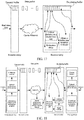
- FIG. 2 An overall block diagram of a real-time voice/video call is shown in FIG. 2 .
- a client B encodes and sends received data collected by an audio adapter. The data is transmitted to a client A over a network (by using an original data flow).
- the client A receives and decodes the data (that is, data transmitted in the original data flow), and sends the decoded data to an audio adapter for playing.
- the client A may send a retransmission request (that is, a request in a retransmission request data flow) to the client B.
- the client B After receiving the retransmission request, the client B retransmits required data to the client A.
- the retransmitted data is response data in a retransmission response data flow.
- a network for example, a network with a limited bandwidth
- a packet loss is caused by congestion
- network load is further increased, and congestion becomes severer.
- Retransmission in this case wastes a bandwidth, and may cause severer network congestion. Severer network congestion causes more packet losses, and deteriorates call quality. Consequently, a vicious circle is formed.
- a real-time voice call feature is not considered in the transmission method, either.
- a real-time call has a strict requirement on an arrival time of data.
- packet loss detection, sending of the retransmission request, and receiving of the response data need to consume a certain time. If the time is excessively long, even though the response data reaches a receive end through retransmission, the response data is useless to real-time communication. In such a network situation, a usage rate of retransmitted data is low, or the data is even useless.
- a method embodiment of a call method is provided.
- FIG. 3A is a flowchart of an optional call method according to an embodiment of this application. As shown in FIG. 3A , the method may include the following steps:
- steps S302 to step S308 when a packet loss occurs in first media information, whether to send a retransmission request is determined based on network status information.
- the retransmission request is sent to obtain a lost data packet, so that media information is more complete.
- the retransmission request is not sent, to avoid aggravating network congestion. Therefore, a technical problem of poor instant messaging quality caused by network congestion in a related technology can be resolved, and instant messaging quality can be improved.
- determining the preset condition may include the following steps:
- a length of time when a data packet sent to the first client is retained by the second client in a buffer is limited. Therefore, if the second client has discarded the first media information, even though the retransmission request reaches the second client, obviously, the second data packet cannot be successfully obtained.
- a packet loss may even occur in the retransmission request when the retransmission request is sent to the second client. Therefore, the requested retransmission fails due to the loss of the retransmission request. Therefore, in this embodiment, a parameter such as a probability about the requested retransmission is first determined based on transmission status information of current received first media information.
- the predetermined parameter may be a parameter agreed in advance, or may be dynamically determined based on a type of the first media information that is currently transmitted between the first client and the second client. For example, transmission of a voice data packet and a video data packet may correspond to different first probability thresholds and different second probability thresholds.
- statistics may be collected on a probability of successfully obtaining a retransmitted data packet by using the retransmission request. Only when the probability is higher than the first probability threshold, the retransmission request is sent to request the retransmitted data packet.
- a network condition that is required when a probability that the successfully retransmitted second data packet is output is not less than the second probability threshold may be further determined.
- the retransmission request is sent only when a current network situation satisfies the first network condition or the second network condition.
- a manner in which the retransmission request is directly sent when a packet loss occurs without defining any network condition such a manner can effectively reduce a frequency of sending the retransmission request, reduce severer congestion caused by retransmission requests still frequently sent when the network has been congested, and apply a valid bandwidth to transmission of useful media information as far as possible.
- the determining, based on the predetermined parameter, a preset condition that the network status information needs to satisfy when retransmission is requested includes at least one of the following:
- a length of time when the second client buffers the first media information may vary with different types of transmission scenarios.
- the first network condition required for ensuring that a probability of successfully retransmitting the second data packet reaches at least the first probability threshold is calculated by using various retransmission models and the like.
- the requested retransmitted data packet is successfully retransmitted, but when the first client receives the data packet, a time at which the first client needs to output the data packet has actually elapsed, and the data packet is not output. Therefore, in this embodiment, network conditions required for ensuring that the requested retransmitted data packet can be successfully retransmitted and is actually used are determined.
- a network condition that current network status information needs to satisfy is determined based on the predetermined parameter.
- the determining, based on the predetermined parameter, a preset condition that the network status information needs to satisfy when retransmission is requested includes: determining, based on a buffer time when the second client buffers the first media information, a first network condition required when the retransmission request reaches the second client within the buffer time without being less than the first probability threshold.
- the determining, based on the predetermined parameter, a preset condition that the network status information needs to satisfy when retransmission is requested further includes: determining, based on an output rate of media information in the first client, a second network condition required when the second data packet is output without being less than the second probability threshold after reaching the first client.
- the media information output rate herein may be the number of voice data packets output in unit of time or an amount of voice data output in unit of time in a voice case, or may be the number of image frames output in unit of time, that is, corresponding to a frame rate or the like, in a video case.
- the client may be a client for communication.
- the client may be installed on a computer or other fixed devices or mobile devices.
- the client may be a client having a relatively high requirement on communication instantaneity, that is, an instant messaging client, for example, WeChat, QQ, or other applications that can be used to provide an instant messaging service.
- the fixed device may include: a desktop computer, a smart television (TV), or the like.
- the mobile device may include: a mobile phone, a tablet computer, a wearable device, or the like.
- the preset network is a network for communication between clients, for example, the Internet connecting two clients.
- clients for example, a client A is located in Haidian District in Beijing, and a client B is located in Chaoyang District in Beijing; servers connecting the client A and the client B are also deployed in Haidian District and Chaoyang District.
- the preset network may include a network connecting Haidian District and Chaoyang District.
- the preset network herein may be a network for transmitting the first media information.
- the first media information may be dynamic multi-media information such as a video, audio, or a GIF picture, or may be static information such as text information or a static picture.
- the network status information is information for describing a network communication status, for example, information such as a network transmission speed or delay.
- the network condition refers to a least network resource that needs to be occupied for transmitting the second data packet and/or a worst network communication state that the network needs to provide, for example, a condition for defining a minimum network transmission speed or a minimum delay of the preset network that needs to be reached for retransmitting the second data packet.
- the retransmission request is sent once a packet loss occurs.
- the sent retransmission request undoubtedly aggravates network congestion, resulting in more data packet losses.
- the response data packet may be invalid. Consequently, communication quality cannot be improved; on the contrary, more data packet losses are caused due to severer network congestion.
- the retransmission request is not sent when the network is not in a desired situation, to avoid aggravating network congestion. Compared with the means used in the related technology, the technical solution of this application can reduce subsequent packet losses, and improve communication quality.
- Step S302 to step S308 may be performed by a client receiving a data packet (that is, the first client). That is, the first client sends the retransmission request to the second client depending on a need of the first client.
- step S302 to step S308 may alternatively be performed by an application server to which the client belongs.
- the server monitors a data packet receiving status of the first client, and requests a lost data packet from the second client depending on a network status after determining a packet loss.
- the server herein may be a client server. For example, when the client is an instant messaging application, the server is an instant messaging application server.
- a current network feature is analyzed based on historical data, whether the retransmission request is sent is determined depending on the network feature and importance of received voice data, and a related retransmission control policy is adjusted in real time based on a utilization rate of retransmitted data, so that a utilization rate of a bandwidth and a usage rate of retransmission are both optimized in various network conditions.
- An optional implementation is shown in FIG. 3 :
- the determining, based on a first data packet that is sent by a second client and received by a first client over a preset network, whether a packet loss occurs in first media information that is sent by the second client to the first client over the preset network may be implemented in the following manner: determining whether a packet loss occurs in the first media information based on sequence number index information in the first data packet.
- whether a packet loss occurs may be determined based on consecutiveness of sequence number indexes. For example, if data packets with indexes 7 and 9 are received, it may be determined that a data packet with an index 8 is lost.
- an index range of a plurality of data packets of a specific piece of media information are indicated in the data packets. For example, a piece of voice in an instant messaging application may be divided into 100 data packets for sending, and an index range 301 to 400 used for the voice may be indicated in the data packets. In this way, any lost data packet may be determined based on a received data packet.
- step S304 when it is determined that a packet loss occurs in the first media information, network status information of the preset network is obtained.
- the obtained information mainly includes a current used bandwidth, a current transmission delay, and a current packet loss rate that are used to represent a first network state, and a second preset value used to describe an allowed number of consecutive lost packets.
- the current used bandwidth is used to indicate a current used bit rate.
- the used bit rate refers to a bit rate actually used in a current call, and includes a transmit bit rate and a receive bit rate.
- the transmit bit rate is obtained by dividing the total number of sent bytes by a call duration.
- the receive bit rate is obtained by dividing the total number of received bytes by the call duration. For example, if an estimated bandwidth (that is, a bandwidth threshold) is far greater than a current used transmit bit rate, it indicates that a bandwidth is sufficient, more packets can be retransmitted, and no pressure is caused to the network.
- the estimated bandwidth indicates a rough bandwidth status of a link in the current call, and is a real-time variable.
- a bandwidth threshold is determined based on bandwidth information of the preset network
- a transmission delay threshold is determined based on network jitter information of the preset network
- a packet loss rate threshold is determined based on a historical packet loss rate and a packet loss model.
- a packet loss rate includes a long-time packet loss rate (that is, a packet loss rate from the beginning of a call to a current moment), a short-time packet loss rate (for example, a packet loss rate within five seconds, used to indicate whether a network packet loss rate has a burst change), and a cumulative histogram of the numbers of consecutive lost packets (used to represent a packet loss model, that is, whether a network type with uniform packet losses or a network type with large burst packet losses).
- a long-time packet loss rate that is, a packet loss rate from the beginning of a call to a current moment
- a short-time packet loss rate for example, a packet loss rate within five seconds, used to indicate whether a network packet loss rate has a burst change
- a cumulative histogram of the numbers of consecutive lost packets used to represent a packet loss model, that is, whether a network type with uniform packet losses or a network type with large burst packet losses.
- a transmission delay is a time required by a data block to enter a transmission medium from a node when the node sends data, that is, all time required by a station from the beginning to the end of sending a data frame (or all time required by a receive station to receive a data frame sent by another station).
- step S306 or S308 after the network status information of the preset network is obtained, and before the retransmission request is sent to the second client or sending of the retransmission request to the second client is canceled, it is determined whether a first network state of the preset network indicated by the network status information matches a second network state required for retransmitting the second data packet. It is determined that the network status information satisfies the preset condition when the first network state matches the second network state. It is determined that the network status information does not satisfy the preset condition when the first network state does not match the second network state.
- the determining whether a first network state of the preset network indicated by the network status information matches a second network state required for retransmitting the second data packet includes at least one of the following: determining whether a difference between a bandwidth threshold and a current used bandwidth is less than a first preset value; determining whether a current transmission delay is less than a transmission delay threshold; determining whether a current packet loss rate is less than a packet loss rate threshold; and determining whether the number of consecutive lost packets is less than a second preset value.
- a preset determining result is used to indicate that the first network state matches the second network state, and the preset determining result includes at least one of the following: determining that the difference between the bandwidth threshold and the current used bandwidth is less than the first preset value; determining that the current transmission delay is less than the transmission delay threshold; determining that the current packet loss rate is less than the packet loss rate threshold; or determining that the number of consecutive lost packets is less than the second preset value.
- a voice feature of the lost second data packet is determined by performing signal feature analysis on a media information segment in the first data packet; and the sending a retransmission request to the second client when the network status information satisfies the preset condition includes: sending the retransmission request to the second client when the network status information satisfies the preset condition and the voice feature includes at least one of a voiced feature, the voice feature, or a semantic feature.
- a voice signal may be analyzed, for example, unvoiced and voiced analysis, voice activity analysis, or semantic importance analysis is performed, to adjust a network parameter threshold.
- the retransmission request may be sent once a packet loss is detected; in a case of an insufficient bandwidth, the retransmission request is sent only for a lost important voice frame (that is, a voice frame satisfying one or more of the voiced feature, the voice feature, or the semantic feature).
- a voice data packet including an important semantic meaning is retransmitted.
- the method further includes: determining whether data content of the lost second data packet is of a predetermined type when determining that a packet loss occurs in the first media information; and correspondingly, in this case, step S304 includes: obtaining network status information of the preset network when the data content is of the predetermined type.
- the video information includes: a key frame and a non-key frame.
- the data content of the second data packet is a non-key frame, it does not matter much to playing of the first media information.
- step S304 may be omitted.
- the method further includes at least one of the following: determining a current bandwidth threshold based on a previous determined bandwidth threshold and current bandwidth information of the preset network; increasing the packet loss rate threshold and decreasing the transmission delay threshold when a first proportion of the number of received second data packets to the number of sent retransmission requests is less than a third preset value; or decreasing the packet loss rate threshold and increasing the transmission delay threshold when a second proportion of received valid second data packets to all received second data packets is less than a fourth preset value.
- the valid second data packet is a data packet satisfying a real-time requirement, that is, a data packet received within a preset time after being lost.
- initial values may be empirically set for thresholds such as the bandwidth threshold, the packet loss rate threshold, and the transmission delay threshold.
- the initial values of the thresholds are used when step S302 to step S308 are performed at the first time, and may be automatically adjusted depending on a network status and an actual feedback status during running, to improve voice communication quality.
- the thresholds may be gradually increased or decreased based on a specific percentage (for example, 10%) of current values of the parameters, to avoid an over-adjustment, and achieve smooth transition.
- step S306 or S308 After step S306 or S308 is completed, after the retransmission request is sent to the second client, the second data packet sent by the second client is received, and second media information is generated based on the first data packet and the second data packet; or when the network status information does not satisfy the preset condition, third media information is generated based on the first data packet.
- the recovered and generated second media information is the first media information, that is, a complete piece of voice can be obtained through recovery. Due to a voice loss, that is, a packet loss, the third media information has lower quality than the first media information.
- a retransmission control procedure mainly includes the following steps:
- request control of step S32 is sending a retransmission request once detecting a packet loss, but a bandwidth also needs to be consumed to send retransmission request information.
- excess bandwidth consumption may aggravate network congestion, and deteriorate call quality, or a utilization rate of retransmitted data is low due to a real-time call feature. In this case, it is unnecessary to send the retransmission request information in step S32.
- a network feature, a utilization rate of retransmission, and the like are not considered, either. Therefore, in such a retransmission control method, neither a utilization rate of retransmitted data nor a utilization rate of a bandwidth is controlled depending on different network features.
- the used bit rate refers to a bit rate actually used in a current call, and includes a transmit bit rate and a receive bit rate.
- the transmit bit rate is obtained by dividing the total number of sent bytes by a call duration.
- the receive bit rate is obtained by dividing the total number of received bytes by the call duration. For example, if an estimated bandwidth is 512 kbps, and a current used transmit bit rate is 100 kbps, it indicates that a bandwidth is sufficient, more packets can be retransmitted, and no pressure is caused to a network.
- the estimated bandwidth indicates a rough bandwidth status of a link in the current call, and is a real-time variable.
- the packet loss rate includes a long-time packet loss rate (that is, a packet loss rate from the beginning of a call to a current moment), a short-time packet loss rate (for example, a packet loss rate within five seconds, used to indicate whether a network packet loss rate has a burst change), and a cumulative histogram of the numbers of consecutive lost packets (used to represent a packet loss model, that is, whether a network type with a uniform packet loss or a network type with large burst packet losses).
- a long-time packet loss rate that is, a packet loss rate from the beginning of a call to a current moment
- a short-time packet loss rate for example, a packet loss rate within five seconds, used to indicate whether a network packet loss rate has a burst change
- a cumulative histogram of the numbers of consecutive lost packets used to represent a packet loss model, that is, whether a network type with a uniform packet loss or a network type with large burst packet losses.
- the network jitter is a conception in quality of service (QoS), and refers to a variation of a packet delay. If the network is congested, a queuing delay affects an end-to-end delay, and packet delays of transmissions over a same connection are different. The jitter is used to describe such a delay variation.
- QoS quality of service
- Step S404 Calculate a corresponding network parameter threshold based on an analysis result in step S403.
- the estimated bandwidth is 512 kbps, and the current used bit rate is 100 kbps, it indicates that a bandwidth is sufficient, and the retransmission request may be sent when a packet loss is detected.
- the estimated bandwidth is 512 kbps, and the used bit rate is 450 kbps, it indicates that a remaining bandwidth is not quite sufficient.
- the retransmission request is sent only when a packet loss rate is greater than 15% and a cumulative histogram of the numbers of consecutive lost packets shows that losses of a plurality of (for example, four) or more consecutive packets accounts for a relatively large proportion.
- Step S405. Collect statistics on a related utilization rate of a retransmission request.
- the network bandwidth, the transmission delay, and the like are all estimated values, an actual effect may be still not desired even if proper control is performed based on parameters such as the estimated bandwidth, the used bit rate, the packet loss rate, and the transmission delay. For example, bandwidth estimation may be insufficiently accurate.
- bandwidth estimation may be insufficiently accurate.
- After a packet is retransmitted a transmission delay becomes larger due to network congestion. Many retransmission requests are sent, while few retransmission responses are received. In this case, a proportion of the number of pieces of received response data to the number of ARQ requests is low. For example, 1000 retransmission requests are sent, while only one ARQ response packet is received. In this case, a retransmission request frequency needs to be decreased.
- the decrease is not made once by a large value, but implemented by gradually increasing a related network parameter.
- the ARQ request is previously allowed to be sent when a packet loss rate is greater than 10% and a transmission delay is less than 200 ms, but now the thresholds are increased, and the ARQ request is allowed to be sent only when a packet loss rate is greater than 20% and a transmission delay is less than 150 ms.
- Step S407. Perform signal feature analysis.
- a signal is analyzed. For example, unvoiced and voiced analysis, voice activity analysis, or semantic importance analysis is performed, to adjust the network parameter threshold in step S406. For example, in a case of a sufficient bandwidth, the retransmission request may be sent once a packet loss is detected; in a case of an insufficient bandwidth, the retransmission request is sent only for a lost important voice frame.
- the estimated bandwidth is 512 kbps, and the used bit rate is 100 kbps, it indicates that a bandwidth is sufficient, and the retransmission request may be sent once a packet is lost.
- the estimated bandwidth is 512 kbps, and the used bit rate is 460 kbps, it indicates that a bandwidth is not quite sufficient, and the retransmission request is sent only when a lost packet is important information.
- Step S408. Perform comprehensive request determining.
- Step S409 Disallow an ARQ request to be sent.
- Step S410 Allow the ARQ request to be sent.
- sending of the retransmission request is adapted to different network features, so that a utilization rate of a bandwidth and retransmission efficiency are both optimized in various network environments.
- the methods in the above embodiments may be implemented by software plus a necessary universal hardware platform or by hardware only. In most circumstances, the former is a preferred implementation.
- the technical solutions of the embodiments of this application essentially, or the part contributing to the existing technology may be implemented in a form of a software product.
- the computer software product may be stored in a storage medium (such as a read-only memory (ROM)/random-access memory (RAM), a magnetic disk, or an optical disc), and include several instructions for instructing a terminal device (which may be a mobile phone, a computer, a server, a network device, or the like) to perform the methods according to the embodiments of this application.
- the call method further includes: obtaining a de-jittering parameter based on current network status information and a second de-jittering policy, and setting, based on the de-jittering parameter, a capacity of a buffer for transmitting call data of the voice call or the video call, so that a delay of the voice call or the video call meets expectation.
- the de-jittering parameter may be obtained by using the second de-jittering policy, and call quality can be improved by performing de-jittering processing in the voice call or the video call.
- the method further includes: collecting offline network data, and extracting at least one network parameter for representing a network feature from the offline network data; constructing a network model based on the at least one network parameter, and determining a first de-jittering policy based on the network model; and modifying the first de-jittering policy based on a feature parameter for evaluating call quality of the voice call or the video call, to obtain the second de-jittering policy.
- the modifying the first de-jittering policy based on a feature parameter for evaluating call quality of the voice call or the video call, to obtain the second de-jittering policy includes:
- the modifying the first de-jittering policy based on a feature parameter for evaluating call quality of the voice call or the video call, to obtain the second de-jittering policy includes:
- the modifying the first de-jittering policy based on a feature parameter for evaluating call quality of the voice call or the video call, to obtain the second de-jittering policy includes:
- the method further includes:
- the method further includes:
- the client in this embodiment of this application corresponds to a smart terminal (for example, a mobile terminal), and may be implemented in various forms.
- the mobile terminal described in this embodiment of this application may include a mobile terminal such as a mobile phone, a smart phone, a notebook computer, a digital broadcast receiver, a personal digital assistant (PDA), a tablet computer (PAD), a portable media player (PMP), or a navigation apparatus, and a fixed terminal such as a digital TV or a desktop computer.
- PDA personal digital assistant
- PAD tablet computer
- PMP portable media player
- a navigation apparatus a fixed terminal such as a digital TV or a desktop computer.
- a terminal is a mobile terminal.
- the configuration according to this embodiment of this application can also be applied to a terminal of a fixed type, except for an element particularly used for a purpose of movement.
- FIG. 9 is a schematic diagram of hardware entities performing information exchange according to an embodiment of this application.
- FIG. 9 includes: a terminal device 1, a server 2, and a terminal device 3.
- the terminal device 1 is referred to as a transmit-end device, and includes terminal devices 11 to 14.
- the terminal device 3 is referred to as a receive-end device, and includes terminal devices 31 to 35.
- the server 2 is configured to execute de-jittering processing logic.
- the terminal devices exchange information with the server over a wired network or a wireless network.
- the terminal device includes types such as a mobile phone, a desktop, a PC, and an all-in-one computer. In this embodiment of this application, the terminal device 1 performs information transmission and exchange with the terminal device 3 via the server 2.
- a call in this application may be a voice call or a video call.
- VoIP Voice over Internet Protocol
- the terminal devices 11 to 14 send network data in a current VoIP network call
- the server 2 performs de-jittering processing on the network data
- the terminal devices 31 to 35 play the network data, to complete the current VoIP network call.
- a de-jittering policy constructed by using a single parameter is not accurate, and call quality of a VoIP network call is affected.
- processing logic 10 in the server 2 performing de-jittering processing includes: S1. Collect offline network data, and extract at least one network parameter for representing a network feature from the offline network data. S2. Construct a network model based on the at least one network parameter, and determine a first de-jittering policy based on the network model. S3.
- S4. Obtain a de-jittering parameter based on a current real-time network status and the second de-jittering policy, and set, based on the de-jittering parameter, a size of a buffer for transmitting data of the voice call or the video call such as the VoIP call, so that a delay of the voice call or the video call such as the VoIP call meets expectation.
- FIG. 9 is merely a system architecture example for implementing this embodiment of this application. This embodiment of this application is not limited to the system structure in FIG. 9 . Various method embodiments of this application are provided based on the system architecture in FIG. 9 .
- An embodiment of this application provides an information processing method. As shown in FIG. 10 , the method includes the following steps: Collect offline network data, extract at least one network parameter for representing a network feature from the offline network data, construct a network model based on the at least one network parameter, to measure or simulate VoIP call quality based on the network model, and determine a first de-jittering policy based on the network model (101).
- the first de-jittering policy may also be referred to as an initial de-jittering policy.
- a large amount of existing-network-related network data is collected based on different network types, and the network model is constructed through offline training.
- the network model can be used to determine the initial de-jittering policy; besides, because a related parameter output based on the initial de-jittering policy includes a de-jittering parameter, a delay parameter, and the like, the initial de-jittering policy and the related parameter may be described as being determined based on the network model, where the related parameter includes the de-jittering parameter and the delay parameter.
- a feature parameter for example, historical data of a current call, signal content of the current call, or an auditory perception result of the current call
- the historical data of the current call can reflect a network feature of the current call.
- the signal content of the current call decides whether a current frame is an important frame. Voice data content is an important frame and requires attention, while silent data content does not require attention. Different content corresponds to different de-jittering processing. For the auditory perception result, different auditory perception results correspond to different de-jittering adjustment manners and amplitudes.
- a size of a de-jittering buffer is determined based on the de-jittering parameter obtained by using the second de-jittering policy, and finally data in the buffer is adjusted based on the size of the de-jittering buffer.
- offline network data is collected, and at least one network parameter for representing a network feature is extracted from the offline network data.
- a network model is constructed based on the at least one network parameter.
- a first de-jittering policy is determined based on the network model. Because a de-jittering algorithm is constructed by using a plurality of parameters, full estimation is performed for various complex situations in a network call environment, the obtained first de-jittering policy (or referred to as an initial de-jittering policy) tends to be accurate, and a related parameter, for example, a de-jittering parameter, obtained based on this initial de-jittering policy also tends to be accurate.
- the first de-jittering policy is further modified based on a feature parameter for evaluating quality of a voice call or a video call such as a VoIP call, to obtain a second de-jittering policy.
- a de-jittering parameter is obtained based on a current real-time network status and the second de-jittering policy, and a size of a buffer for transmitting data of the voice call or the video call such as the VoIP call is set based on the de-jittering parameter, so that a delay of the voice call or the video call such as the VoIP call meets expectation.
- the size of the buffer that is set accordingly tends to be proper. It is instructive to improve network call quality based on the size of the buffer, and the network call quality is improved.
- collection, policy determining, policy modification, and other logic in processing logic of the method are not limited to being located on a transmit end, a receive end, or a server, and the logic may be all or partially located on the transmit end, the receive end, or the server.
- An embodiment of this application provides an information processing method. As shown in FIG. 11 , the method includes the following steps: Collect offline network data, extract at least one network parameter for representing a network feature from the offline network data, construct a network model based on the at least one network parameter, to measure or simulate VoIP call quality based on the network model, and determine a first de-jittering policy based on the network model (201).
- the first de-jittering policy may also be referred to as an initial de-jittering policy.
- a large amount of existing-network-related network data is collected based on different network types, and the network model is constructed through offline training.
- the network model can be used to determine the initial de-jittering policy; besides, because a related parameter output based on the initial de-jittering policy includes a de-jittering parameter, a delay parameter, and the like, the initial de-jittering policy and the related parameter may be described as being determined based on the network model, where the related parameter includes the de-jittering parameter and the delay parameter.
- Obtain historical data of a current call use the historical data of the current call as a feature parameter for evaluating quality of a voice call or a video call such as a VoIP call, and modify the first de-jittering policy based on the historical data of the current call, to obtain a second de-jittering policy (202).
- the historical data of the current call can reflect a network feature of the current call.
- setting of a network parameter, for example, a de-jittering parameter and a delay processing parameter, in the first de-jittering policy may be adjusted based on the historical data of the current call.
- Obtain a de-jittering parameter based on a current real-time network status and the second de-jittering policy and set, based on the de-jittering parameter, a size of a buffer for transmitting data of the voice call or the video call such as the VoIP call, so that a delay of the voice call or the video call such as the VoIP call meets expectation, and tends to be proper (203).
- a size of a de-jittering buffer is determined based on the de-jittering parameter obtained by using the second de-jittering policy, and finally data in the buffer is adjusted based on the size of the de-jittering buffer.
- An embodiment of this application provides an information processing method. As shown in FIG. 12 , the method includes the following steps: Collect offline network data, extract at least one network parameter for representing a network feature from the offline network data, construct a network model based on the at least one network parameter, to measure or simulate VoIP call quality based on the network model, and determine a first de-jittering policy based on the network model (301).
- the first de-jittering policy may also be referred to as an initial de-jittering policy.
- a large amount of existing-network-related network data is collected based on different network types, and the network model is constructed through offline training.
- the network model can be used to determine the initial de-jittering policy; besides, because a related parameter output based on the initial de-jittering policy includes a de-jittering parameter, a delay parameter, and the like, the initial de-jittering policy and the related parameter may be described as being determined based on the network model, where the related parameter includes the de-jittering parameter and the delay parameter.
- Obtain signal content of a current call use the signal content of the current call as a feature parameter for evaluating quality of a voice call or a video call such as a VoIP call, and modify the first de-jittering policy based on the signal content of the current call, to obtain a second de-jittering policy (302).
- the signal content of the current call decides whether a current frame is an important frame.
- Voice data content is an important frame and requires attention, while silent data content does not require attention.
- Different content corresponds to different de-jittering processing.
- setting of a network parameter, for example, a de-jittering parameter and a delay processing parameter, in the first de-jittering policy may be adjusted.
- the modified de-jittering policy may be further modified based on the signal content of the current call, to improve precision of the de-jittering policy.
- a size of a de-jittering buffer is determined based on the de-jittering parameter obtained by using the second de-jittering policy, and finally data in the buffer is adjusted based on the size of the de-jittering buffer.
- An embodiment of this application provides an information processing method. As shown in FIG. 13 , the method includes the following steps: Collect offline network data, extract at least one network parameter for representing a network feature from the offline network data, construct a network model based on the at least one network parameter, to measure or simulate VoIP call quality based on the network model, and determine a first de-jittering policy based on the network model (401).
- the first de-jittering policy may also be referred to as an initial de-jittering policy.
- a large amount of existing-network-related network data is collected based on different network types, and the network model is constructed through offline training.
- the network model can be used to determine the initial de-jittering policy; besides, because a related parameter output based on the initial de-jittering policy includes a de-jittering parameter, a delay parameter, and the like, the initial de-jittering policy and the related parameter may be described as being determined based on the network model, where the related parameter includes the de-jittering parameter and the delay parameter.
- an auditory perception result which may also be referred to as a conventional auditory perception evaluation parameter, of a current call
- use the auditory perception result of the current call as a feature parameter for evaluating quality of a voice call or a video call such as a VoIP call
- modify the first de-jittering policy based on the auditory perception result of the current call to obtain a second de-jittering policy (402).
- different auditory perception results correspond to different de-jittering adjustment manners and amplitudes.
- setting of a network parameter for example, a de-jittering parameter and a delay processing parameter, in the first de-jittering policy may be adjusted.
- the modified de-jittering policy may be further modified based on the auditory perception result of the current call, to improve precision of the de-jittering policy.
- a feature parameter for example, historical data of the current call or signal content of the current call
- the modified de-jittering policy may be further modified based on the auditory perception result of the current call, to improve precision of the de-jittering policy.
- a size of a de-jittering buffer is determined based on the de-jittering parameter obtained by using the second de-jittering policy, and finally data in the buffer is adjusted based on the size of the de-jittering buffer.
- different delay processing methods and parameters may be further set on a transmit end and a receive end (or referred to as a playing end) based on different processing capabilities of devices, scheduling features of application program threads, or the like, so that the first de-jittering policy is further modified, to improve precision of the de-jittering policy, as described in the following embodiment.
- a current call for example, a voice call or a video call such as a VoIP call
- different processing capabilities of terminal devices and/or a scheduling feature of an application used as a medium of the voice call or the video call such as the VoIP call are obtained, and the first de-jittering policy is modified based on the different processing capabilities of the terminal devices and/or the scheduling feature of the application used as the medium of the voice call or the video call such as the VoIP call.
- the receive end (or referred to as the playing end) in the entire VoIP network call
- a current call for example, a voice call or a video call such as a VoIP call
- different processing capabilities of terminal devices and/or a scheduling feature of an application used as a medium of the voice call or the video call such as the VoIP call are obtained, and the first de-jittering policy is modified based on the different processing capabilities of the terminal devices and/or the scheduling feature of the application used as the medium of the voice call or the video call such as the VoIP call.
- a corresponding parameter for representing a network feature may be first extracted through offline packet capturing, different network parameter models are established through lots of offline training, an initial de-jittering algorithm and a related parameter are determined based on the established network parameter models, and then the de-jittering policy and the related parameter are adjusted based on historical data of a current call. Because both an overall network feature in an entire call process and burstiness within a period of time are considered in network model establishment, a network feature can be estimated more accurately.
- JB_len represents a size of a buffer
- AD_up represents an upper limit of the buffer
- AD_dw represents a lower limit of the buffer
- F1 to F4 represent empirical values for parameter adjustment. Specific content is as follows:
- JB_len>AD_up ⁇ F1 if current frame signal content is an important frame (for example, a voice segment), current data in the buffer is compressed. If a current frame is non-important data (for example, silent data), the current frame is directly discarded.
- JB_len>AD_up ⁇ F2 F1>F2
- current frame signal content is an important frame (for example, a voice segment)
- current data in the buffer is not processed. If a current frame is non-important data (for example, silent data), current data in the buffer is compressed.
- Compression amplitudes are determined based on values of F1 and F2, and an amplitude of each compression is less than a data length of the current frame.
- a basis of such processing is because: compressing and directly discarding a signal both cause impairment to call quality, but direct packet discarding causes greater impairment than compression.
- Based on a compression algorithm of a single packet an amplitude of each compression is less than a data length of one frame. Therefore, compared with directly discarding a current frame, data compression reduces a length of data in the buffer at a lower speed, that is, an end-to-end delay is decreased at a lower speed. Therefore, the method in which a frame is directly discarded is used only when the length of data in the buffer is very large and current data is non-important data. If the length of data in the buffer is very large but current data is important data, a manner causing less impairment, that is compression, is used to adjust the buffer length.
- JB_len ⁇ AD_dw ⁇ F3 if a current frame is a non-important frame, the current frame is directly copied repeatedly, the number of copies is determined based on a value of F3. If a current frame is an important frame, current data in the buffer is expanded. When JB_len ⁇ AD_dw ⁇ F4 (F3 ⁇ F4), the current buffer is expanded. An amplitude of each expansion is determined based on values of F3 and F4.
- a basis of such processing is because: although expanding and directly copying data also cause impairment to sound, compared with a sound pause caused because data in the buffer is empty, such impairment causes much less impact on call experience. Therefore, when the length of data in the buffer is found to be less than a lower limit of adjustment, in principle, a fast response is made and a size of data in the buffer is adjusted as soon as possible.
- data in the buffer is directly decoded and sent to an audio adapter device without any de-jittering processing.
- a proper adjustment for example, specifying maximum consecutive expansion or compression times
- a historical adjustment policy to ensure that no fast playing or slow playing effect is caused to final auditory perception.
- the method further includes:
- the determining whether the first client and the second client are in a both-speaking state in which the first client and the second client collect sound at the same time includes:
- the method before the superimposing an ultrasonic signal on the far-end signal, the method further includes:
- the obtaining a far-end signal includes:
- the determining a first signal segment in the mixed signal and a second signal segment in the near-end signal based on the ultrasonic signal includes:
- the determining a first signal segment in the mixed signal and a second signal segment in the near-end signal based on the ultrasonic signal includes:
- data information carried in the ultrasonic signal superimposed on the far-end signal is not repetitive within a predetermined period; and the predetermined period is greater than or equal to a maximum value of an echo delay, and the echo delay is a delay between a time at which the speaker part plays the mixed signal and a time at which the microphone part collects an echo corresponding to the mixed signal.
- the data information carried in the ultrasonic signal includes ultrasonic codes, each of the ultrasonic codes includes at least two code parts, and each of the code parts is used to indicate whether a signal exists at each of at least two ultrasonic frequencies.
- the calculating a correlation value between the first signal segment and the second signal segment includes:
- the method further includes:
- FIG. 21 is a flowchart of a call status detection method according to an exemplary embodiment.
- the call status detection method may include the following steps: Step S201. Receive a sound signal sent by a peer end of a voice call.
- a terminal may receive a sound signal sent by a peer end of a call.
- the sound signal may be a sound signal sent over a PSTN, or may be a sound signal sent over a data network.
- Step S202 Perform low-pass filtering on the received sound signal to obtain a far-end signal.
- the far-end signal is a signal carrying sound uttered by the peer end of the voice call.
- a cut-off frequency of the low-pass filtering is lower than a lowest frequency of an ultrasonic wave.
- a normal frequency of a voice signal is relatively low, and usually ranges from hundreds to thousands of Hertz, while the received sound signal may carry some high-frequency interference signals, and these high-frequency interference signals may include an ultrasonic signal.
- signal detection and alignment need to be implemented through ultrasonic signal superimposition. If the sound signal sent by the peer end of the voice call carries an ultrasonic signal, interference may be caused to a subsequent superimposed ultrasonic signal, and signal alignment accuracy may be affected, thereby affecting accuracy of both-speaking state detection.
- the terminal after receiving the sound signal sent by the peer end of the voice call, the terminal first perform low-pass filtering on the sound signal, to remove a high-frequency interference signal from the received sound signal.
- a cut-off frequency of the low-pass filtering is lower than a lowest frequency of an ultrasonic wave, to avoid causing interference to an ultrasonic signal superimposed on the far-end signal in a subsequent step.
- a lowest frequency of an ultrasonic signal is 20 KHz
- the cut-off frequency of the low-pass filtering may range from the normal frequency of the voice signal to the lowest frequency of the ultrasonic signal.
- the cut-off frequency may be 12 KHz. Then the terminal obtains a signal below 12 KHz in the received sound signal as a far-end signal.
- Step S203 Detect whether a power value of the far-end signal is greater than a preset power threshold. If yes, step S204 is performed, or otherwise, step S211 is performed.
- the far-end signal is required to generate an echo that can be collected by the microphone part. Therefore, in this embodiment of this application, after obtaining the far-end signal, the terminal first determines whether the power value of the far-end signal is greater than the preset power threshold. If yes, it indicates that power of the far-end signal is relatively high, and after the far-end signal is played by a speaker part, the microphone part can collect an echo signal. On the contrary, if the power value of the far-end signal is not greater than the preset power threshold, it indicates that power of the far-end signal is relatively low, and after the far-end signal is played by the speaker part, the microphone part may not collect an echo signal.
- the power value of the far-end signal is also used to determine whether the peer end of the voice call is uttering sound. If the power value of the far-end signal is greater than the preset power threshold, it indicates that the peer end of the voice call is uttering sound, for example, a user on the peer end is speaking; in this case, step S204 is performed for subsequent detection. If the power value of the far-end signal is not greater than the preset power threshold, it indicates that the peer end of the voice call is not uttering sound, or the peer end of the voice call utters very small sound, for example, the user on the peer end is not speaking; in this case, step 205 is performed.
- the terminal may divide the far-end signal into frames based on a fixed time length (for example, 20 ms), and calculate a power value of each far-end signal frame.
- P x ( n ) is the power value of the n th frame
- M is a frame length
- x is a sampling value of the far-end signal.
- Step S204 Superimpose an ultrasonic signal on the far-end signal to obtain a mixed signal in which the ultrasonic signal is superimposed.
- a conventional microphone part uses a sampling frequency of 48 KHz. According to the Shannon sampling theorem, a maximum frequency of a signal collected by the microphone part is 24 KHz. To enable the microphone part to collect an echo signal in which an ultrasonic signal is superimposed, in this embodiment of this application, a frequency of the ultrasonic signal superimposed on the far-end signal needs to be lower than the maximum frequency of the signal collected by the microphone part. Specifically, for example, when a sampling frequency of the microphone part is 48 KHz, a frequency range of the ultrasonic signal superimposed on the far-end signal may be set to 20 KHz to 22 KHz.
- the terminal needs to encode the ultrasonic signal superimposed on the far-end signal, so that data information carried in the ultrasonic signal superimposed on the far-end voice signal is not repetitive within a predetermined period.
- the predetermined period is greater than or equal to a maximum value of an echo delay.
- the echo delay is a delay between a time at which the speaker part plays the mixed signal and a time at which the microphone part collects an echo corresponding to the mixed signal.
- the data information carried in the ultrasonic signal is used to indicate a frequency corresponding to the ultrasonic signal.
- the data information carried in the ultrasonic signal includes ultrasonic codes, each ultrasonic code includes at least two code parts, and each code part is used to indicate whether a signal exists at each of at least two ultrasonic frequencies.
- each ultrasonic code includes three code parts, each code part is used to indicate whether a signal exists at each of three ultrasonic frequencies, and a code design for the ultrasonic signal may be as follows:
- A is an amplitude value of the ultrasonic signal
- a value range of t is [0, M-1]
- b 0 , b 1 , and b 2 are assignment switches of three corresponding frequencies (that is, values of b 0 , b 1 , and b 2 are 0 or 1). Therefore, a code part may represent a value of 0 to 7.
- value ranges of first and second code parts are set to 1 to 7, while a third code part is set to 0. In this way, a maximum of 49 ultrasonic codes having different values can be constructed, and a code table having a size of 49 may be designed by using the 49 ultrasonic codes having different values.
- the code table is sequentially read to obtain corresponding ultrasonic codes, and after being constructed based on the ultrasonic signal formula, the ultrasonic signal is superimposed on the far-end signal (by adding up values of sampling points of the signals, that is, amplitude values of the signals).
- the last piece of data in the code table is sequentially read, when data in the code table is read next time, reading starts from the first piece of data in the code table.
- the data in the code table is cyclically read in such a manner to construct an ultrasonic signal.
- the code part that is set to 0 is used to indicate a boundary between two adjacent ultrasonic codes superimposed on the far-end signal.
- the code part that is set to 0 may alternatively be the first code part or the second code part.
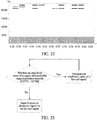
- FIG. 22 is a spectrum graph of a mixed signal according to an embodiment of this application. In FIG.
- the terminal superimposes an ultrasonic signal corresponding to a same code part on each 0.02-s time length, but the ultrasonic signal is not superimposed on the last 0.02-s time length in every 0.06s, or in other words, a code value of a code part corresponding to an ultrasonic signal superimposed on the last 0.02-s time length is 0.
- the ultrasonic signal superimposed on each 0.06-s time length is used to indicate an ultrasonic code.
- Each ultrasonic code has a different code value within a predetermined period. Specifically, in FIG.
- a code value of a code part is indicated by using values of b 2 , b 1 , and b 0
- a code value of an ultrasonic code is indicated by using code values of three code parts.
- a code value of a code part is 000 (that is, 0). That is, within 0.36s to 0.42s, a code value of an ultrasonic code corresponding to an ultrasonic signal superimposed on the far-end signal is "360". Similarly, within 0.42s to 0.48s, a code value of an ultrasonic code corresponding to an ultrasonic signal superimposed on the far-end signal is "540".
- the terminal may further detect whether an amplitude value of a sound signal obtained after the ultrasonic signal is superimposed on the far-end signal exceeds a preset amplitude value range, and attenuates an amplitude value of the far-end signal based on a predetermined attenuation policy if the amplitude value of the sound signal exceeds the preset amplitude value range.
- a value of a sampling point of a signal is represented by using 16-bit data, that is, a maximum of 216 different signal sampling values are represented.
- Each amplitude value in a voice signal corresponds to a signal sampling value, that is, a voice signal having an amplitude value within [32767, -32768] can be accurately indicated, but a voice signal beyond the amplitude value range cannot be accurately indicated, leading to cracking voice during voice playing.
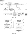
- amplitude value attenuation may be performed on a far-end signal having an excessively large amplitude value. Specifically, referring to FIG. 23, FIG.
- FIG. 23 is a schematic flowchart of far-end signal attenuation according to an embodiment of this application.
- the far-end signal may be attenuated based on a predetermined attenuation policy, and it is detected whether an amplitude value of a sound signal obtained after the ultrasonic signal is superimposed on the attenuated far-end signal exceeds [32767, -32768]. If the amplitude value of the obtained sound signal is within [32767, -32768], the ultrasonic signal is superimposed on the far-end signal to obtain a mixed signal.
- the attenuating the far-end signal based on a predetermined attenuation policy may be specifically attenuating the far-end signal at a predetermined attenuation proportion. For example, each time the far-end signal is attenuated, an amplitude value of the far-end signal may be multiplied by the attenuation proportion, to obtain the attenuated far-end signal.
- the attenuation proportion may be a positive number less than 1.
- the attenuation proportion may be 0.9 or 0.8.
- an amplitude value of an ultrasonic signal (that is, A in the foregoing formula) needs to be an appropriate value, so that the terminal can accurately detect an ultrasonic signal in a near-end signal collected by the microphone part, and cracking voice is prevented from appearing in a mixed signal in which the ultrasonic signal is superimposed due to an excessively high amplitude value of the ultrasonic signal, and affecting a call effect.
- the amplitude value of the ultrasonic signal may be set to 3000.
- Step S205 Play the mixed signal by using a speaker part.
- the terminal when playing the mixed signal by using the speaker part, the terminal also locally buffers the mixed signal for subsequent signal alignment.
- Step 206 Obtain a near-end signal, where the near-end signal is a sound signal collected by a microphone part.
- the near-end signal is a sound signal collected by the terminal by using the microphone part, and includes an echo signal collected by the microphone part after the sound signal played by the speaker part is reflected to the microphone part, and a sound signal locally generated by the terminal. That is, the near-end signal collected by the microphone part includes the far-end signal played by the speaker part, the ultrasonic signal superimposed on the far-end signal, and the sound signal locally generated by the terminal (for example, sound when a user of the terminal speaks).
- Step 207 Determine a first signal segment in the mixed signal and a second signal segment in the near-end signal based on the ultrasonic signal.
- the first signal segment is a time-domain signal segment in the mixed signal.
- the second signal segment is a time-domain signal segment in the near-end signal.
- the terminal may first determine the second signal segment in the near-end signal, and then determine the first signal segment in the mixed signal based on an ultrasonic signal included in the second signal segment. For example, when determining the first signal segment and the second signal segment, the terminal may parse data information carried in an ultrasonic signal included in the near-end signal, determine a time-domain signal in the near-end signal and corresponding to an ultrasonic signal carrying target data information as the second signal segment, determine a playing time of a mixed signal that is played recently and in which the ultrasonic signal carrying the target data information is superimposed, and determine a signal, played at the playing time, in the mixed signal as the first signal segment.
- the terminal may analyze an ultrasonic frequency band of a signal collected by the microphone, and obtain code information of an ultrasonic signal based on the foregoing code rule. For example, the terminal analyzes the collected near-end signal by using a Fast Fourier Transformation (FFT) analysis method, determines power values at three ultrasonic frequencies: f 0 , f 1 , and f 2 in the collected near-end signal, and detects whether the power values at the three ultrasonic frequencies are greater than a specific threshold. If yes, it indicates that a signal exists at a corresponding frequency, or otherwise, it is considered that no signal exists at a corresponding frequency.
- FFT Fast Fourier Transformation
- the complete ultrasonic code is the target data information.
- the three adjacent near-end signal frames Cap(i) are the second signal segment.
- a played mixed signal is searched for three adjacent mixed signal frames Play(i) that carry the same ultrasonic code and are played recently, and the mixed signal Play(i) and the current collected near-end signal Cap(i) are aligned. That is, the current collected near-end signal Cap(i) includes an echo signal corresponding to Play(i), and the mixed signal Play(i) is the first signal segment corresponding to the near-end signal Cap(i).
- a time length of each near-end signal frame and a time length of each mixed signal frame are the same as the time length of each far-end signal frame in the foregoing step, for example, 20 ms.
- the terminal may first determine a playing time of a mixed signal that is played recently and in which an ultrasonic signal carrying the complete ultrasonic code is superimposed, and determine a signal played at the playing time as the mixed signal Play(i).
- the terminal detects that a signal exists at the frequencies f 2 , f 1 , and f 0 in the near-end signal, and within 0.37s to 0.43s, a code value of an ultrasonic code corresponding to an ultrasonic signal at the frequencies f 2 , f 1 , and f 0 in the near-end signal is "360", and the terminal determines through query that in the mixed signal corresponding to FIG. 22 , a code value of an ultrasonic code corresponding to an ultrasonic signal carried in the mixed signal within 0.36s to 0.42s is also "360 ".
- the near-end signal collected within 0.37s to 0.43s and the mixed signal within 0.36s to 0.42s in FIG. 22 includes the same ultrasonic signal. That is, the mixed signal played within 0.36s to 0.42s in FIG. 22 is the first signal segment, and the near-end signal collected within 0.37s to 0.43s is the second signal segment.
- the terminal may first determine the first signal segment in the mixed signal, and then determine the second signal segment in the near-end signal based on an ultrasonic signal included in the first signal segment. For example, when determining the first signal segment and the second signal segment, the terminal may determine a time-domain signal in the mixed signal and corresponding to an ultrasonic signal carrying target data information as the first signal segment, query the near-end signal collected after the first signal segment is played for a time-domain signal corresponding to the ultrasonic signal carrying the target data information, and determine an obtained signal as the second signal segment.
- the terminal may determine three adjacent mixed signal frames Play(ii) in the mixed signal and carrying an ultrasonic code as a first signal segment, analyze a near-end signal collected by the microphone part after the first signal segment is played, and query the near-end signal collected after the first signal segment is played for three adjacent near-end signal frames Cap(ii) including the same ultrasonic code as the mixed signal Play(ii).
- the near-end signal Cap(ii) is a second signal segment corresponding to the mixed signal Play(ii).
- Step S208 Calculate a correlation value between the first signal segment and the second signal segment.
- the terminal may separately calculate power spectrums respectively corresponding to the first signal segment and the second signal segment by means of FFT, perform binarization processing on the power spectrums respectively corresponding to the first signal segment and the second signal segment, to obtain binary arrays respectively corresponding to the first signal segment and the second signal segment, and calculate a correlation value between the binary arrays respectively corresponding to the first signal segment and the second signal segment.
- the terminal when calculating power spectrums respectively corresponding to the first signal segment and the second signal segment, the terminal may calculate power spectrums respectively corresponding to the first signal segment and the second signal segment on a specified frequency band.
- the specified frequency band may be a frequency band on which most sound is located in the voice call process.
- the specified frequency band may be 500 Hz to 1200 Hz.
- smooth filtering may be performed on the power spectrum of the signal, to obtain a power smoothed value at each frequency in the power spectrum of the signal, and binarization processing is performed on the power spectrum of the signal based on the power spectrum of the signal and the power smoothed value at each frequency in the power spectrum of the signal, to obtain a binary array corresponding to the signal.
- FIG. 24 is a schematic flowchart of correlation value calculation according to an embodiment of this application.
- the terminal performs FFT on the first signal segment to obtain a power spectrum P p ( j ) of the first signal segment on 500 Hz to 1200 Hz.
- M is a half of the number of FFT points, and f s is a sampling frequency of the first signal segment.
- the terminal performs smooth filtering on P p ( j ) to obtain P psm ( j ), where P psm ( j ) represents a power smoothed value of P p ( j ) at each frequency.
- the terminal performs binarization on P p ( j ) based on P psm ( j ) . Specifically, for each frequency in P p ( j ) , a power value of the frequency is compared with a power smoothed value corresponding to the frequency in P psm ( j ).
- a value of the frequency is set to 1, or otherwise, a value of the frequency is set to 0, to finally obtain a binary array P pb ( j ) of P p (j ) .
- the terminal also performs FFT on the second signal segment to obtain a power spectrum P c ( j ) of the second signal segment on 500 Hz to 1200 Hz, performs smooth filtering on P c ( j ) to obtain P csm ( j ) , where P csm ( j ) represents a power smoothed value at each frequency in P c ( j ).
- the terminal performs binarization on P c ( j ) based on P csm ( j ) to obtain a binary array P cb ( j ) of P c ( j ) .
- the terminal calculates a correlation value between P pb ( j ) and P cb ( j ) .
- the calculated correlation value may be used as a correlation value between the first signal segment and the second signal segment on the specified frequency band.
- Step S209 Determine whether the correlation value is less than a preset correlation value threshold. If yes, step 210 is performed, or otherwise, step S211 is performed.
- the correlation value threshold may be a threshold preset by a developer.
- Step S210 Determine that a call state is a both-speaking state.
- a call state when the microphone part collects the near-end signal is the both-speaking state when it is determined in step S209 that the correlation value is less than the preset correlation value threshold.
- Step S211 Determine that a call state is a non-both-speaking state.
- a call state when the far-end signal is obtained is the non-both-speaking state when it is determined in step S203 that the power value of the far-end signal is not greater than preset power threshold.
- a call state when the microphone part collects the near-end signal is the non-both-speaking state when it is determined in step S209 that the correlation value is not less than the preset correlation value threshold.
- a near-end signal collected by the microphone part of the terminal includes a locally generated sound signal (for example, speaking voice of the user of the terminal) and an echo signal that reaches the microphone part after the mixed signal is transmitted.
- a larger correlation value calculated in step S208 means that the echo signal has a larger percentage in the near-end signal, and the locally generated sound signal has a smaller percentage in the near-end signal.
- the calculated correlation value is smaller, it indicates that the echo signal has a smaller percentage in the near-end signal, and the locally generated sound signal has a larger percentage in the near-end signal.
- the calculated correlation value is less than the preset correlation value threshold, it may be considered that signal strength of the locally generated sound signal is relatively high, and it is very likely that the user of the terminal is speaking; further, when it is determined in step S203 that the power value of the far-end signal is greater than the preset power threshold, it may be determined that a call state corresponding to the near-end signal is a both-speaking state.
- the calculated correlation value is not less than the preset correlation value threshold, it may be considered that signal strength of the locally generated sound signal is relatively low, and the user of the terminal may be not speaking; therefore, it may be determined that a call state corresponding to the near-end signal is a non-both-speaking state.
- FIG. 25 is a schematic diagram of a call status detection procedure according to an embodiment of this application.
- a terminal when receiving a sound signal sent by a peer end of a call, a terminal performs low-pass filtering on the received sound signal to obtain a far-end signal, determines whether power of the far-end signal is greater than a preset power threshold, and if the power of the far-end signal is not greater than the power threshold, determines that a current call state is a non-both-speaking state. If the power of the far-end signal is greater than the power threshold, the terminal superimposes an ultrasonic signal on the far-end signal to obtain a mixed signal, and stores the mixed signal.
- the terminal plays the mixed signal by using a speaker part, obtains a sound signal collected by a microphone part as a near-end signal, aligns the mixed signal and the near-end signal by parsing out codes carried in an ultrasonic signal in the near-end signal, determines a first signal segment in the mixed signal and a second signal segment in the near-end signal that include the same ultrasonic signal, calculates a correlation value between the first signal segment and the second signal segment, and if the calculated correlation value is less than a correlation value threshold, determines that a current call state is a both-speaking state, or otherwise, determines that a current call state is the non-both-speaking state.
- the terminal aligns the mixed signal and the near-end signal by using the ultrasonic signal superimposed on the far-end signal and the ultrasonic signal included in the near-end signal collected by the microphone part, and determines whether the call state is the both-speaking state based on the correlation value between the aligned near-end signal and mixed signal.
- the solution in this application can improve accuracy of both-speaking state detection.
- the terminal aligns the mixed signal and the near-end signal by using the ultrasonic signal inaudible to human, avoiding causing interference to a normal call of a user.
- FIG. 26 is a structural block diagram of a call status detection apparatus according to an exemplary embodiment.
- the call status detection apparatus can perform all or some steps in the embodiment shown in FIG. 21 .
- the call status detection apparatus may include:
- the apparatus further includes:
- the signal obtaining part includes:
- data information carried in the ultrasonic signal superimposed on the far-end voice signal is not repetitive within a predetermined period; and the predetermined period is greater than or equal to a maximum value of an echo delay, and the echo delay is a delay between a time at which the speaker part plays the mixed signal and a time at which the microphone part collects an echo corresponding to the mixed signal.
- the signal determining part includes:
- the signal determining part includes:
- the data information carried in the ultrasonic signal is used to indicate a frequency corresponding to the ultrasonic signal.
- the data information carried in the ultrasonic signal includes ultrasonic codes, each of the ultrasonic codes includes at least two code parts, and each of the code part is used to indicate whether a signal exists at each of at least two ultrasonic frequencies.
- the correlation value calculation part includes:
- the apparatus further includes:
- the mixed signal and the near-end signal are aligned by using the ultrasonic signal superimposed on the far-end signal and the ultrasonic signal included in the near-end signal collected by the microphone part, and whether the call state is the both-speaking state is determined based on the correlation value between the aligned near-end signal and mixed signal.
- the solution in this application can improve accuracy of both-speaking state detection.
- the terminal aligns the mixed signal and the near-end signal by using the ultrasonic signal inaudible to human, avoiding causing interference to a normal call of a user.
- FIG. 5 is a schematic diagram of an optional call apparatus according to an embodiment of this application. As shown in FIG. 5 , the apparatus may include: a first judging part 52, a first obtaining part 54, a first execution part 56, and a second execution part 58.
- the first judging part 52 is configured to determine, based on a first data packet that is sent by a second client and received by a first client over a preset network, whether a packet loss occurs in first media information that is sent by the second client to the first client over the preset network, the first media information including the first data packet, and the first media information being media information transmitted in a voice call or a video call between the second client and the first client.
- the first obtaining part 54 is configured to obtain network status information of the preset network when it is determined that a packet loss occurs in the first media information.
- the first execution part 56 is configured to send a retransmission request to the second client when the network status information satisfies a preset condition, the retransmission request being used to request the second client to retransmit a lost second data packet in the first media information, and the preset condition being used to indicate a network condition of the preset network that is required for retransmitting the second data packet.
- the second execution part 58 is configured to cancel sending of the retransmission request to the second client when the network status information does not satisfy the preset condition.
- the transmission apparatus further includes:
- the parameter determining part and the condition determining part correspond to a processor or a processing circuit, and may be configured to determine a current preset condition about whether to send a retransmission request.
- the first judging part 52 in this embodiment may be configured to perform step S302 in Embodiment 1 of this application
- the first obtaining part 54 in this embodiment may be configured to perform step S304 in Embodiment 1 of this application
- the first execution part 56 in this embodiment may be configured to perform step S306 in Embodiment 1 of this application
- the second execution part 58 in this embodiment may be configured to perform step S308 in Embodiment 1 of this application.
- the parts have the same implementation example and application scenario as corresponding steps, but are not limited to the content disclosed in Embodiment 1. It should be noted that, as a portion of the apparatus, the parts may run in the hardware environment shown in FIG. 1 , and may be implemented by software, or may be implemented by hardware.
- the client may be a client for communication.
- the client may be installed on a computer or a mobile device.
- the client may be a client having a relatively high requirement on communication instantaneity, that is, an instant messaging client, for example, WeChat or QQ.
- the preset network is a network for communication between clients.
- the media information may be dynamic multi-media information, such as a video, audio, or a GIF picture, or may be static information, such as text information or a static picture.
- the network status information is information for describing a network feature, for example, information such as a network transmission speed or delay.
- the retransmission request is sent once a packet loss occurs.
- the sent retransmission request undoubtedly aggravates network congestion, resulting in more data packet losses.
- the response data packet may be invalid. Consequently, communication quality cannot be improved; on the contrary, more data packet losses are caused due to severer network congestion.
- the retransmission request is not sent when the network is not in a desired situation, to avoid aggravating network congestion. Compared with the means used in the related technology, the technical solution of this application can reduce subsequent packet losses, and improve communication quality.
- the first judging part 52, the first obtaining part 54, the first execution part 56, and the second execution part 58 may be disposed on a first client. That is, the first client sends a retransmission request to a second client depending on a need of the first client. To reduce running load of the first client, the first judging part 52, the first obtaining part 54, the first execution part 56, and the second execution part 58 may alternatively be disposed on an application server.
- the server monitors a data packet receiving status of the first client, and requests a lost data packet from the second client depending on a network status after determining a packet loss.
- the server herein may be a client server. For example, when the client is an instant messaging application, the server is an instant messaging application server.
- a current network feature is analyzed based on historical data, whether the retransmission request is sent is determined depending on the network feature and importance of received voice data, and a related retransmission control policy is adjusted in real time based on a utilization rate of retransmitted data, so that a utilization rate of a bandwidth and a usage rate of retransmission are both optimized in various network conditions.
- a utilization rate of a bandwidth and a usage rate of retransmission are both optimized in various network conditions.
- the first judging part is further configured to determine whether a packet loss occurs in the first media information based on sequence number index information in the first data packet.
- whether a packet loss occurs may be determined based on consecutiveness of sequence number indexes. For example, if data packets with indexes 7 and 9 are received, it may be determined that a data packet with an index 8 is lost.
- an index range of a plurality of data packets of a specific piece of media information are indicated in the data packets. For example, a piece of voice in an instant messaging application may be divided into 100 data packets for sending, and an index range 301 to 400 used for the voice may be indicated in the data packets. In this way, any lost data packet may be determined based on a received data packet.
- the apparatus further includes: a second obtaining part, configured to: before it is determined whether the first network state of the preset network indicated by the network status information matches the second network state required for retransmitting the second data packet, obtain the current used bandwidth, the current transmission delay, and the current packet loss rate that are used to represent the first network state, and the second preset value used to describe an allowed number of consecutive lost packets; a third determining part, configured to determine the bandwidth threshold based on bandwidth information of the preset network; a fourth determining part, configured to determine the transmission delay threshold based on network jitter information of the preset network; and a fifth determining part, configured to determine the packet loss rate threshold based on a historical packet loss rate and a packet loss model.
- a second obtaining part configured to: before it is determined whether the first network state of the preset network indicated by the network status information matches the second network state required for retransmitting the second data packet, obtain the current used bandwidth, the current transmission delay, and the current packet loss rate that are used to represent the first network
- the apparatus further includes: a second judging part, configured to: after the network status information of the preset network is obtained, and before the retransmission request is sent to the second client or sending of the retransmission request to the second client is canceled, determine whether a first network state of the preset network indicated by the network status information matches a second network state required for retransmitting the second data packet; a first determining part, configured to determine that the network status information satisfies the preset condition when the first network state matches the second network state; and a second determining part, configured to determine that the network status information does not satisfy the preset condition when the first network state does not match the second network state.
- a second judging part configured to: after the network status information of the preset network is obtained, and before the retransmission request is sent to the second client or sending of the retransmission request to the second client is canceled, determine whether a first network state of the preset network indicated by the network status information matches a second network state required for retransmitting the second
- the second judging part includes: a first judging subpart, configured to determine whether a difference between a bandwidth threshold and a current used bandwidth is less than a first preset value; a second judging subpart, configured to determine whether a current transmission delay is less than a transmission delay threshold; a third judging subpart, configured to determine whether a current packet loss rate is less than a packet loss rate threshold; and a fourth judging subpart, configured to determine whether the number of consecutive lost packets is less than a second preset value; where a preset determining result is used to indicate that the first network state matches the second network state, and the preset determining result includes at least one of the following: determining that the difference between the bandwidth threshold and the current used bandwidth is less than the first preset value; determining that the current transmission delay is less than the transmission delay threshold; determining that the current packet loss rate is less than the packet loss rate threshold; or determining that the number of consecutive lost packets is less than the second preset value.
- the apparatus further includes: a first update part, configured to: after the retransmission request is sent to the second client or sending of the retransmission request to the second client is canceled, determine a current bandwidth threshold based on a previous determined bandwidth threshold and current bandwidth information of the preset network; a second update part, configured to increase the packet loss rate threshold and decrease the transmission delay threshold when a first proportion of the number of received second data packets to the number of sent retransmission requests is less than a third preset value; and a third update part, configured to decrease the packet loss rate threshold and increase the transmission delay threshold when a second proportion of received valid second data packets to all received second data packets is less than a fourth preset value.
- a first update part configured to: after the retransmission request is sent to the second client or sending of the retransmission request to the second client is canceled, determine a current bandwidth threshold based on a previous determined bandwidth threshold and current bandwidth information of the preset network
- a second update part configured to increase the packet loss rate threshold and decrease
- the thresholds may be gradually increased or decreased based on a specific percentage (for example, 10%) of current values of the parameters, to avoid an over-adjustment, and achieve smooth transition.
- the apparatus further includes: a sixth determining part, configured to: before the retransmission request is sent to the second client, determine a voice feature of the lost second data packet by performing signal feature analysis on a media information segment in the first data packet; and the first execution part is further configured to send the retransmission request to the second client when the network status information satisfies the preset condition and the voice feature includes at least one of a voiced feature, the voice feature, or a semantic feature.
- a sixth determining part configured to: before the retransmission request is sent to the second client, determine a voice feature of the lost second data packet by performing signal feature analysis on a media information segment in the first data packet
- the first execution part is further configured to send the retransmission request to the second client when the network status information satisfies the preset condition and the voice feature includes at least one of a voiced feature, the voice feature, or a semantic feature.
- a voice signal may be analyzed, for example, unvoiced and voiced analysis, voice activity analysis, or semantic importance analysis is performed, to adjust the network parameter threshold.
- the retransmission request may be sent once a packet loss is detected; in a case of an insufficient bandwidth, the retransmission request is sent only for a lost important voice frame.
- a voice data packet including an important semantic meaning is retransmitted.
- the apparatus further includes: a receiving part 60, configured to: after the retransmission request is sent to the second client, receive the second data packet sent by the second client; a first generation part 62, configured to generate second media information based on the first data packet and the second data packet; and a second generation part 64, configured to: when the network status information does not satisfy the preset condition, generate third media information based on the first data packet.
- a receiving part 60 configured to: after the retransmission request is sent to the second client, receive the second data packet sent by the second client
- a first generation part 62 configured to generate second media information based on the first data packet and the second data packet
- a second generation part 64 configured to: when the network status information does not satisfy the preset condition, generate third media information based on the first data packet.
- the recovered second media information is the first media information, that is, a complete piece of voice can be obtained through recovery. Due to a voice loss, that is, a packet loss, the third media information has lower quality than the first media information.
- An embodiment of this application provides an information processing apparatus.
- the apparatus includes the following parts: A collection part is configured to collect offline network data, and extract at least one network parameter for representing a network feature from the offline network data.
- a policy determining part is configured to construct a network model based on the at least one network parameter, and determine a first de-jittering policy based on the network model, to measure or simulate VoIP call quality based on the network model.
- the first de-jittering policy may also be referred to as an initial de-jittering policy.
- the network model can be used to determine the initial de-jittering policy; besides, because a related parameter output based on the initial de-jittering policy includes a de-jittering parameter, a delay parameter, and the like, the initial de-jittering policy and the related parameter may be described as being determined based on the network model, where the related parameter includes the de-jittering parameter and the delay parameter.
- a policy modification part is configured to modify the first de-jittering policy based on a feature parameter (for example, historical data of a current call, signal content of the current call, or an auditory perception result of the current call) for evaluating quality of a voice call or a video call such as a VoIP call, to obtain a second de-jittering policy.
- a feature parameter for example, historical data of a current call, signal content of the current call, or an auditory perception result of the current call
- the historical data of the current call can reflect a network feature of the current call.
- the signal content of the current call decides whether a current frame is an important frame. Voice data content is an important frame and requires attention, while silent data content does not require attention. Different content corresponds to different de-jittering processing. For the auditory perception result, different auditory perception results correspond to different de-jittering adjustment manners and amplitudes.
- a buffer adjustment part is configured to obtain a de-jittering parameter based on a current real-time network status and the second de-jittering policy, and set, based on the de-jittering parameter, a size of a buffer for transmitting data of the voice call or the video call such as the VoIP call, so that a delay of the voice call or the video call such as the VoIP call meets expectation, and tends to be proper.
- a size of a de-jittering buffer is determined based on the de-jittering parameter obtained by using the second de-jittering policy, and finally data in the buffer is adjusted based on the size of the de-jittering buffer.
- offline network data is collected, and at least one network parameter for representing a network feature is extracted from the offline network data.
- a network model is constructed based on the at least one network parameter.
- a first de-jittering policy is determined based on the network model. Because a de-jittering algorithm is constructed by using a plurality of parameters, full estimation is performed for various complex situations in a network call environment, the obtained first de-jittering policy (or referred to as an initial de-jittering policy) tends to be accurate, and a related parameter, for example, a de-jittering parameter, obtained based on this initial de-jittering policy also tends to be accurate.
- the first de-jittering policy is further modified based on a feature parameter for evaluating quality of a voice call or a video call such as a VoIP call, to obtain a second de-jittering policy.
- a de-jittering parameter is obtained based on a current real-time network status and the second de-jittering policy, and a size of a buffer for transmitting data of the voice call or the video call such as the VoIP call is set based on the de-jittering parameter, so that a delay of the voice call or the video call such as the VoIP call meets expectation.
- the size of the buffer that is set accordingly tends to be proper. It is instructive to improve network call quality based on the size of the buffer, and the network call quality is improved.
- the collection part, the policy determining part, and the policy modification part in the apparatus are not limited to being located on a transmit end, a receive end, or a server, and these parts may be all or partially located on the transmit end, the receive end, or the server.
- the policy modification part is configured to: obtain historical data of a current call, and modify the first de-jittering policy based on the historical data of the current call.
- the policy modification part is configured to: obtain signal content of a current call, and modify the first de-jittering policy based on the signal content of the current call.
- the policy modification part is configured to: obtain an auditory perception result of a current call, and modify the first de-jittering policy based on the auditory perception result.
- the apparatus further includes: a call collection part, configured to collect data of a current call, for example, a voice call or a video call such as a VoIP call.
- the policy modification part is configured to: when collection of the data of the current call, for example, the voice call or the video call such as the VoIP call, is triggered, obtain different processing capabilities of terminal devices and/or a scheduling feature of an application used as a medium of the voice call or the video call such as the VoIP call, and modify the first de-jittering policy based on the different processing capabilities of the terminal devices and/or the scheduling feature of the application used as the medium of the voice call or the video call such as the VoIP call.
- the apparatus further includes: a call playing part, configured to play data of a current call, for example, a voice call or a video call such as a VoIP call.
- the policy modification part is configured to: when playing of the data of the current call, for example, the voice call or the video call such as the VoIP call, is triggered, obtain different processing capabilities of terminal devices and/or a scheduling feature of an application used as a medium of the voice call or the video call such as the VoIP call, and modify the first de-jittering policy based on the different processing capabilities of the terminal devices and/or the scheduling feature of the application used as the medium of the voice call or the video call such as the VoIP call.
- An embodiment of this application provides an information processing system, including a transmit end (or referred to as a collection end) 41, a de-jittering end 42, and a receive end (or referred to as a playing end) 43.
- Processing logic of the transmit end includes: collecting offline network data, and extracting at least one network parameter for representing a network feature from the offline network data, where the at least one network parameter is used to construct a network model, and the network model is used to determine a first de-jittering policy when data of a voice call or a video call such as a VoIP call is transmitted; obtaining different processing capabilities of terminal devices and/or a scheduling feature of an application used as a medium of the voice call or the video call such as the VoIP call when collecting the data of the current call, for example, the voice call or the video call such as the VoIP call; and modifying the first de-jittering policy based on the different processing capabilities of the terminal devices and/or the scheduling feature of the application used as the medium of the voice call or
- Processing logic of the de-jittering end includes: constructing the network model based on the at least one network parameter, and determining the first de-jittering policy based on the network model, where the at least one network parameter comes from the parameter extracted from the collected offline network data and used to represent a network feature; modifying the first de-jittering policy based on a feature parameter for evaluating quality of the voice call or the video call such as the VoIP call, to obtain a second de-jittering policy; and obtaining a de-jittering parameter based on a current real-time network status and the second de-jittering policy, and setting, based on the de-jittering parameter, a size of a buffer for transmitting data of the voice call or the video call such as the VoIP call, so that a delay of the voice call or the video call such as the VoIP call meets expectation, and tends to be proper.
- the modifying the first de-jittering policy based on a feature parameter for evaluating quality of the voice call or the video call such as the VoIP call includes: obtaining historical data of a current call, and modifying the first de-jittering policy based on the historical data of the current call.
- the modifying the first de-jittering policy based on a feature parameter for evaluating quality of the voice call or the video call such as the VoIP call includes: obtaining signal content of a current call, and modifying the first de-jittering policy based on the signal content of the current call.
- the modifying the first de-jittering policy based on a feature parameter for evaluating quality of the voice call or the video call such as the VoIP call includes: obtaining an auditory perception result of a current call, and modifying the first de-jittering policy based on the auditory perception result.
- Processing logic of the receive end includes: obtaining the first de-jittering policy determined when the data of the voice call or the video call such as the VoIP call, is transmitted, where the first de-jittering policy is obtained based on the network model constructed by using the at least one network parameter, and the at least one network parameter comes from the parameter extracted from the collected offline network data and used to represent a network feature; obtaining different processing capabilities of terminal devices and/or a scheduling feature of an application used as a medium of the voice call or the video call such as the VoIP call when playing the data of the current call, for example, the voice call or the video call such as the VoIP call; and modifying the first de-jittering policy based on the different processing capabilities of the terminal devices and/or the scheduling feature of the application used as the medium of the voice call or the video call such as the VoIP call.
- the information processing system includes a transmit end (or referred to as a collection end) 41, a de-jittering end 42, and a receive end (or referred to as a playing end) 43.
- the transmit end (or referred to as the collection end) 41 includes: a collection part 411, configured to collect offline network data, and extract at least one network parameter for representing a network feature from the offline network data, where the at least one network parameter is used to construct a network model, and the network model is used to determine a first de-jittering policy when data of a voice call or a video call such as a VoIP call, is transmitted; a call collection part 412, configured to obtain different processing capabilities of terminal devices and/or a scheduling feature of an application used as a medium of the voice call or the video call such as the VoIP call when collecting the data of the current call, for example, the voice call or the video call such as the VoIP call; and a first policy modification part 413, configured to modify the first de-jittering policy based
- the de-jittering end 42 includes: a policy determining part 421, configured to construct the network model based on the at least one network parameter, and determine the first de-jittering policy based on the network model, where the at least one network parameter comes from the parameter extracted from the collected offline network data and used to represent a network feature; a second policy modification part 422, configured to modify the first de-jittering policy based on a feature parameter for evaluating quality of the voice call or the video call such as the VoIP call, to obtain a second de-jittering policy; and a buffer adjustment part 423, configured to obtain a de-jittering parameter based on a current real-time network status and the second de-jittering policy, and set, based on the de-jittering parameter, a size of a buffer for transmitting data of the voice call or the video call such as the VoIP call, so that a delay of the voice call or the video call such as the VoIP call meets expectation, and tends to be proper.
- a policy determining part 421 configured to
- the receive end (or referred to as the playing end) 43 includes: an obtaining part 431, configured to obtain the first de-jittering policy determined when the data of the voice call or the video call such as the VoIP call, is transmitted, where the first de-jittering policy is obtained based on the network model constructed by using the at least one network parameter, and the at least one network parameter comes from the parameter extracted from the collected offline network data and used to represent a network feature; a call playing part 432, configured to obtain different processing capabilities of terminal devices and/or a scheduling feature of an application used as a medium of the voice call or the video call such as the VoIP call when playing the data of the current call, for example, the voice call or the video call such as the VoIP call; and a third policy modification part 433, configured to modify the first de-jittering policy based on the different processing capabilities of the terminal devices and/or the scheduling feature of the application used as the medium of the voice call or the video call such as the VoIP call.
- a processor for data processing may be implemented by using a microprocessor, a central processing unit (CPU), a digital signal processor (DSP), or a field-programmable gate array (FPGA) during processing.
- a storage medium includes an operation instruction.
- the operation instruction may be computer-executable code, and steps in the procedure of the information processing method in the foregoing embodiment of this application are implemented by using the operation instruction.
- An embodiment of this application is illustrated as follows by using an actual application scenario as an example:
- a solution of end-to-end delay processing in a voice call or a video call such as a VoIP call according to an embodiment of this application may be used.
- modules included in the voice call or the video call such as the VoIP call from one end to the other end is shown in FIG. 15 .
- An end-to-end delay refers to a time difference starting from when a speaker A speaks to when a listener B hears sound.
- packet transmission is performed on data in a packet form over an IP network. Due to an inherent feature of the IP network, a time consumed to transmit each packet over the network is indeterminate.
- Such a transmission time difference is referred to as a jitter.
- a link with a small jitter may be selected for transmission by means of proper route scheduling.
- the jitter may be processed by increasing a buffer delay.
- a main module for processing the jitter is a "de-jittering & decoding" module in FIG. 15 .
- end-to-end delays mainly include: a device buffer delay (mainly a buffer delay of collection by an audio adapter, and a buffer delay of playing by the audio adapter), a data buffer delay of processing by modules of a VoIP application program (mainly a delay produced by a de-jittering module), and a network transmission delay (uncontrollable).
- a device buffer delay mainly a buffer delay of collection by an audio adapter, and a buffer delay of playing by the audio adapter
- a data buffer delay of processing by modules of a VoIP application program mainly a delay produced by a de-jittering module
- a network transmission delay uncontrollable
- Different delay processing methods and parameters are set based on different processing capabilities of devices, scheduling features of application program threads, or the like.
- an implementation procedure of a first solution includes: determining a network jitter parameter for representing a current network jitter status; adjusting a delay parameter of a jitter buffer based on the current network jitter parameter; and performing delay processing on a data packet in the jitter buffer based on the adjusted delay parameter of the jitter buffer.
- a parameter for representing a current network jitter is first determined, including: recording, by using PktComeThisTime, the number of 10-ms packets that reach the jitter buffer each time, recording a plurality of PktComeThisTime, determining a maximum value in the plurality of PktComeThisTime, and recording the maximum value as Pm; and performing a series of weighted averaging on Pm to obtain a parameter for representing a network jitter J, and adjusting a size of the jitter buffer based on J.
- a network delay dn is predicted or estimated on a receive end based on historical data, and statistics are collected on a packet loss rate of the receive end; then, a current desired size of a de-jittering buffer is obtained based on E-Model by using the estimated network delay and the obtained packet loss rate; and finally, data in the buffer is adjusted based on the buffer size.
- FIG. 18 an overall schematic diagram is shown in FIG. 18 , including: determining a lower adjustment limit value AD_dw and an upper adjustment limit value AD_up for a current buffer size based on a current estimated network status; and determining an adjustment manner and an adjustment amplitude for current data in the buffer based on a current buffer data size JB_len, a value of AD_up/AD_dw, current signal content, and an auditory perception model of human ears.
- collection and playing policies are adjusted based on device performance, so that a data sending speed is more uniform, a speed of obtaining data from the buffer is also more uniform, and a de-jittering module works in an optimum state.
- a specific implementation is as follows:
- JB_len>AD_up ⁇ F1 if current frame signal content is an important frame (for example, a voice segment), current data in the buffer is compressed. If a current frame is non-important data (for example, silent data), the current frame is directly discarded.
- JB_len>AD_up ⁇ F2 F1>F2
- current frame signal content is an important frame (for example, a voice segment)
- current data in the buffer is not processed. If a current frame is non-important data (for example, silent data), current data in the buffer is compressed.
- Compression amplitudes are determined based on values of F1 and F2, and an amplitude of each compression is less than a data length of the current frame.
- a basis of such processing is because compressing and directly discarding a signal are both impairment in call quality, but direct packet discarding causes greater impairment than compression.
- Based on a compression algorithm of a single packet an amplitude of each compression is less than a data length of one frame. Therefore, compared with directly discarding a current frame, data compression reduces a length of data in the buffer at a lower speed, that is, an end-to-end delay is decreased at a lower speed. Therefore, the method in which a frame is directly discarded is used only when the length of data in the buffer is very large and current data is non-important data. If the length of data in the buffer is very large but current data is important data, a manner causing less impairment, that is compression, is used to adjust the buffer length.
- JB_len ⁇ AD_dw ⁇ F3 if a current frame is a non-important frame, the current frame is directly copied repeatedly, the number of copies is determined based on a value of F3. If a current frame is an important frame, current data in the buffer is expanded. When JB_len ⁇ AD_dw ⁇ F4 (F3 ⁇ F4), the current buffer is expanded. An amplitude of each expansion is determined based on values of F3 and F4.
- a basis of such processing is because: although expanding and directly copying data also cause impairment to sound, compared with a sound pause caused because data in the buffer is empty, such impairment causes much less impact on call experience. Therefore, when the length of data in the buffer is found to be less than a lower limit of adjustment, in principle, a fast response is made and a size of data in the buffer is adjusted as soon as possible.
- data in the buffer is directly decoded and sent to an audio adapter device without any de-jittering processing.
- a model is established based on an offline network feature.
- Different network models are established through offline packet capturing, analysis of a large amount of existing network data, and parameter extraction.
- FIG. 19 and FIG. 20 a "time difference between arrivals of two adjacent packets" is extracted from offline data as one of model feature parameters.
- FIG. 19 shows a value range with larger fluctuation, indicating a larger network jitter.
- FIG. 19 for time differences between arrivals of two adjacent packets in a case of a larger jitter, there are fewer burst large jitters.
- FIG. 20 for time differences between arrivals of two adjacent packets in a case of a smaller jitter, there are more burst large jitters.
- FIG. 20 shows more burst large jitters (a relatively large number of time differences between arrivals of two adjacent packets in the figure are greater than 1000 ms).
- a method in RFC 3550 may be used to calculate a conventional jitter value, indicating a network jitter at a current "moment".
- it is usually insufficient, because there are more burst large jitters though an overall jitter is smaller in FIG. 20 .
- Network models in FIG. 19 and FIG. 20 may be distinguished based on "time differences between arrivals of two adjacent packets" through accumulated histogram statistics collection, variance statistics collection, and calculation of smooth envelope values in an entire call process, the number of bursts, and the like.
- model establishment parameters In addition to the "time differences between arrivals of two adjacent packets", the number of consecutive lost packets, an overall packet loss rate, an out-of-order rate, an out-of-order length, and the like may be analyzed as model establishment parameters.
- a de-jittering parameter is adjusted based on a historical network parameter of a current call: De-jittering parameters AD_up and AD_dw are preliminarily determined based on a result of step 1). Then AD_up and AD_dw are adjusted based on historical data of the current call.
- AD_up and AD_dw may be set to be small, to ensure that an overall end-to-end delay is small.
- JB_len ⁇ AD_dw, F3 and F4 may be adjusted, so that an expansion policy becomes more aggressive (an expansion service is broader or more data is copied once), and a response is faster, to achieve better and faster resistance to a burst large jitter.
- a de-jittering parameter is adjusted based on signal content:
- the de-jittering parameter is adjusted (that is, AD_up, AD_dw, or F1 to F4 are adjusted) based on content (music or voice) and an importance level (silent or non-silent) of a current signal. For example, for a music signal, used AD_up and AD_dw need to be as large as possible in a same network status.
- An overall rule is as follows: De-jittering processing is performed on an important frame as less as possible. When a buffer length is greater than AD_up, an adjustment policy may be not processed until a non-important frame appears. When the buffer length is less than AD_dw, an adjustment needs to be made as soon as possible to avoid a pause. Auditory perception quality is ensured to be as desired as possible, and de-jittering processing is performed only when necessary.
- a de-jittering parameter is adjusted based on auditory perception: During expansion, compression, or time length adjustment on a signal, an adjustment frequency needs to be controlled, so that no fast playing or slow playing effect is caused to auditory perception.
- Adaptation of a collection/playing device In FIG. 18 , due to different processing capabilities of devices and different scheduling features of application programs, a packet sending speed is insufficiently uniform or is irregular. However, the de-jittering module is designed based on a uniform or regular packet sending speed.
- a uniform sending speed is mainly determined by a collection manner of an audio adapter and a thread scheduling feature. For example, if an audio adapter callback manner is used to drive the application program to perform encoding/sending, compared with an iOS device, an Android device has more non-uniform time intervals between two audio adapter callbacks. Moreover, a machine with poorer performance encounters more such situations.
- an audio adapter callback or timer callback method may be used based on different device performance to drive the application program to perform encoding/sending, to achieve a more uniform packet sending interval.
- a speed at which the application program obtains data from the buffer needs to be as uniform as possible, so that the de-jittering module can work in an optimum state, to achieve a lowest end-to-end delay.
- thread scheduling in the voice and video call is less uniform than that in the pure-voice call.
- the parameter of the de-jitter algorithm may be properly increased to reduce pauses.
- the subparts have the same implementation example and application scenario as corresponding steps, but are not limited to the content disclosed in Embodiment 1. It should be noted that, as a portion of the apparatus, the subparts may run in the hardware environment shown in FIG. 1 , and may be implemented by software, or may be implemented by hardware.
- the hardware environment includes a network environment.
- An embodiment of this application further provides a server or a terminal for implementing the foregoing method.
- FIG. 7 is a structural block diagram of a terminal according to an embodiment of this application.
- the terminal may include: one or more processors 701 (only one is shown in the figure), a memory 703, and a transmission apparatus 705 (for example, a transmit apparatus in the foregoing embodiment).
- the terminal may further include an input/output device 707.
- the memory 703 may be configured to store a software program and a subpart, for example, program instructions/subparts corresponding to the method and the apparatus in the embodiments of this application.
- the processor 701 performs various function application and data processing, that is, implements the foregoing method, by running the software program and the subpart stored in the memory 703.
- the memory 703 may include a high-speed RAM, and may also include a non-volatile memory, for example, one or more magnetic storage apparatuses, a flash memory, or another non-volatile solid-state memory.
- the memory 703 may further include a memory disposed remote to the processor 701, and the memory may be connected to the terminal over a network. Examples of the network include but are not limited to: the Internet, an intranet, a local area network, a mobile communications network, and a combination thereof.
- the processor 701 may be a central processing unit, a micro processor, a digital signal processor, an application processor, a programmable array, or the like.
- the processor 701 may be connected to the memory 703 by using an integrated circuit bus.
- the transmission apparatus 705 is configured to receive or send data over a network, and may be further configured to transmit data between the processor and the memory.
- Specific examples of the network may include a wired network and a wireless network.
- the transmission apparatus 705 includes a network interface controller (NIC), which may be connected to another network device and a router by using a cable, to communicate with the Internet or the local area network.
- the transmission apparatus 705 is a radio frequency (RF) subpart, configured to wirelessly communicate with the Internet.
- NIC network interface controller
- RF radio frequency
- the memory 703 is configured to store an application program.
- the processor 701 may invoke, by using the transmission apparatus 705, the application program stored in the memory 703, to perform the following steps: determining, based on a first data packet that is sent by a second client and received by a first client over a preset network, whether a packet loss occurs in first media information that is sent by the second client to the first client over the preset network, the first media information including the first data packet, and the first media information being media information transmitted in a voice call or a video call between the second client and the first client; obtaining network status information of the preset network when determining that a packet loss occurs in the first media information; sending a retransmission request to the second client when the network status information satisfies a preset condition, the retransmission request being used to request the second client to retransmit a lost second data packet in the first media information, and the preset condition being used to indicate a network condition of the preset network that is required for retransmitting the second data packet; and canceling sending of the retransmission request to
- the processor 701 is further configured to perform the following steps: after the sending a retransmission request to the second client, receiving the second data packet sent by the second client; generating second media information based on the first data packet and the second data packet; and when the network status information does not satisfy the preset condition, generating third media information based on the first data packet.
- the processor 701 is further configured to perform the following steps: after the obtaining network status information of the preset network, and before the sending a retransmission request to the second client or canceling sending of the retransmission request to the second client, determining whether a first network state of the preset network indicated by the network status information matches a second network state required for retransmitting the second data packet; and determining that the network status information satisfies the preset condition when the first network state matches the second network state; or determining that the network status information does not satisfy the preset condition when the first network state does not match the second network state.
- the processor 701 is further configured to perform the following steps: determining whether a difference between a bandwidth threshold and a current used bandwidth is less than a first preset value; determining whether a current transmission delay is less than a transmission delay threshold; determining whether a current packet loss rate is less than a packet loss rate threshold; and determining whether the number of consecutive lost packets is less than a second preset value; where a preset determining result is used to indicate that the first network state matches the second network state, and the preset determining result includes at least one of the following: determining that the difference between the bandwidth threshold and the current used bandwidth is less than the first preset value; determining that the current transmission delay is less than the transmission delay threshold; determining that the current packet loss rate is less than the packet loss rate threshold; or determining that the number of consecutive lost packets is less than the second preset value.
- a solution of a call method is provided. It is determined, based on a first data packet that is sent by a second client and received by a first client over a preset network, whether a packet loss occurs in first media information that is sent by the second client to the first client over the preset network, the first media information including the first data packet. Network status information of the preset network is obtained when it is determined that a packet loss occurs in the first media information. A retransmission request is sent to the second client when the network status information satisfies a preset condition, the retransmission request being used to request the second client to retransmit a lost second data packet.
- Sending of the retransmission request to the second client is canceled when the network status information does not satisfy the preset condition.
- the lost data packet is obtained by using the retransmission request when allowed in a network situation, so that the media information is more complete. Therefore, instant messaging quality is improved, and a technical problem of poor instant messaging quality caused by network congestion in a related technology is resolved.
- the structure shown in FIG. 7 is merely exemplary, and the terminal may be a terminal device such as a smartphone (such as an Android mobile phone or an iOS mobile phone), a tablet computer, a palmtop computer, a mobile Internet device (MID), and a PAD.
- a terminal device such as a smartphone (such as an Android mobile phone or an iOS mobile phone), a tablet computer, a palmtop computer, a mobile Internet device (MID), and a PAD.
- FIG. 7 imposes no limitation to the structure of the terminal.
- the terminal may further include more or few components (for example, a network interface and a display apparatus) that those shown in FIG. 7 , or has a configuration different from that shown in FIG. 7 .
- the program may be stored in a computer-readable storage medium.
- the storage medium may include: a flash drive, a ROM, a RAM, a magnetic disk, or an optical disc.
- An embodiment of this application further provides a computer storage medium.
- the storage medium may be configured to store a computer-executable instruction, such as program code, for performing the call method.
- the storage medium may be located in at least one of a plurality of network devices in the network described in the foregoing embodiments.
- the computer storage medium may be a non-transitory storage medium.
- the storage medium is configured to store program code for performing the following steps:
- the storage medium is configured to store program code for performing the following steps: after the sending a retransmission request to the second client, receiving the second data packet sent by the second client; and generating second media information based on the first data packet and the second data packet; and when the network status information does not satisfy the preset condition, generating third media information based on the first data packet.
- the storage medium is configured to store program code for performing the following steps: after the obtaining network status information of the preset network, and before the sending a retransmission request to the second client or canceling sending of the retransmission request to the second client, determining whether a first network state of the preset network indicated by the network status information matches a second network state required for retransmitting the second data packet; and determining that the network status information satisfies the preset condition when the first network state matches the second network state; or determining that the network status information does not satisfy the preset condition when the first network state does not match the second network state.
- the storage medium is configured to store program code for performing the following steps: determining whether a difference between a bandwidth threshold and a current used bandwidth is less than a first preset value; determining whether a current transmission delay is less than a transmission delay threshold; determining whether a current packet loss rate is less than a packet loss rate threshold; and determining whether the number of consecutive lost packets is less than a second preset value; where a preset determining result is used to indicate that the first network state matches the second network state, and the preset determining result includes at least one of the following: determining that the difference between the bandwidth threshold and the current used bandwidth is less than the first preset value; determining that the current transmission delay is less than the transmission delay threshold; determining that the current packet loss rate is less than the packet loss rate threshold; or determining that the number of consecutive lost packets is less than the second preset value.
- the storage medium may include, but not limited to, various media that can store program code, such as a USB flash drive, a ROM, a RAM, a removable hard disk, a magnetic disk, or an optical disc.
- program code such as a USB flash drive, a ROM, a RAM, a removable hard disk, a magnetic disk, or an optical disc.
- the transmission delay threshold is determined based on a network jitter.
- a specific jitter when a transmission delay is greater than a specific threshold, a retransmission request is not allowed to be sent, because even though the retransmission request is sent in this case, retransmitted response data may be not used, resulting in a low utilization rate.
- a current packet loss rate threshold is determined based on a historical packet loss rate and packet loss model analysis.
- sending more data means that more data will be lost. In this case, sending the retransmission request increases network load, which is useless or adverse.
- Step S4 Adjust the previously determined related threshold of the network parameter based on a corresponding utilization rate of a retransmission request.
- the corresponding utilization rate herein is one of the foregoing predetermined parameters.
- a proportion of retransmission requests to received response data is calculated.
- Historical data buffered by a client B has a specific length limitation. If a delay of transmission from a client A to the client B is excessively large, data information of a requested packet carried in a retransmission request received by the client B is no longer buffered data, and the client B does not respond to the retransmission request of the client A.
- the proportion of retransmission requests/received response data is particularly small. Therefore, a related threshold, which makes the proportion greater than a specific value, of the network parameter may be obtained based on the proportion.
- a retransmission request sending frequency needs to be lowered, that is, increasing the related threshold of the network parameter, and calculating an actual utilization rate of response data.
- the client B finds corresponding data in historical buffered data, uses the data as a response packet, and sends the response packet to the client A.
- response data may not satisfy a data requirement of a real-time call when reaching the client A, and becomes a late packet and needs to be actively discarded.
- a utilization rate of the response data is low. If the actual utilization rate keeps low within a period of time, the retransmission request frequency also needs to be lowered, that is, increasing the related threshold of the network parameter.
- the related threshold describes the foregoing network condition.
- the integrated part in the foregoing embodiments is implemented in the form of a software functional part and sold or used as an independent product
- the integrated part may be stored in a computer-readable storage medium.
- the software product is stored in a storage medium and includes several instructions for instructing one or more computer devices (which may be a personal computer, a server, a network device, or the like) to perform all or some of the steps of the methods according to the embodiments of this application.
- the disclosed client may be implemented in other manners.
- the described apparatus embodiment is merely exemplary.
- the part division is merely logical function division and may be other division in actual implementation.
- a plurality of parts or components may be combined or integrated into another system, or some features may be ignored or not performed.
- the displayed or discussed mutual couplings or direct couplings or communication connections may be implemented through some interfaces.
- the indirect couplings or communication connections between the parts or subparts may be implemented in electronic or other forms.
- parts described as separate parts may or may not be physically separate, and parts displayed as parts may or may not be physical parts, may be located in one position, or may be distributed on a plurality of network parts. Some or all of the parts may be selected according to actual needs to achieve the objectives of the solutions of the embodiments.
- a network status of a preset network over which a retransmitted data packet is received is obtained, to determine, based on the network status, whether to request retransmission.
- severer congestion of the preset network that is caused by a large number of retransmission requests still sent when the network has been congested can be reduced, so that more resources in the preset network are retained for transmitting new data, thereby improving transmission efficiency, and achieving a positive industrial effect.
- a computer-executable instruction such as a corresponding computer program can be run in a terminal device, thereby achieving high industrial feasibility.
Landscapes
- Engineering & Computer Science (AREA)
- Signal Processing (AREA)
- Computer Networks & Wireless Communication (AREA)
- Environmental & Geological Engineering (AREA)
- Computer Security & Cryptography (AREA)
- Multimedia (AREA)
- Quality & Reliability (AREA)
- Telephonic Communication Services (AREA)
- Data Exchanges In Wide-Area Networks (AREA)
Claims (14)
- Anrufverfahren, umfassend:Bestimmen (S302), basierend auf einem ersten Datenpaket, das über ein voreingestelltes Netzwerk von einem zweiten Client gesendet und von einem ersten Client empfangen wird, ob ein Paketverlust in ersten Medieninformationen auftritt, die von dem zweiten Client an den ersten Client über das voreingestellte Netzwerk gesendet werden, wobei die ersten Medieninformationen das erste Datenpaket umfassen, das anfänglich erfolgreich übertragen wird, und die ersten Medieninformationen Medieninformationen sind, die in einem Sprachanruf oder einem Videoanruf zwischen dem zweiten Client und dem ersten Client übertragen werden;Erhalten (S304) von Netzwerkstatusinformationen des voreingestellten Netzwerks, wenn bestimmt wird, dass ein Paketverlust in den ersten Medieninformationen auftritt;Bestimmen (S3041) eines vorbestimmten Parameters, um den zweiten Client aufzufordern, ein zweites Datenpaket erneut zu übertragen, wobei das zweite Datenpaket ein erneut übertragenes Datenpaket eines erfolglos übertragenen Datenpakets in den ersten Medieninformationen ist; und wobei der vorbestimmte Parameter mindestens einen von einem ersten Wahrscheinlichkeitsschwellenwert eines erneuten Übertragungserfolgs oder einem zweiten Wahrscheinlichkeitsschwellenwert eines Ausgabeerfolgs des zweiten Datenpakets umfasst;Bestimmen (S3042), basierend auf dem vorbestimmten Parameter, einer voreingestellten Bedingung, die die Netzwerkstatusinformation erfüllen muss, wenn eine erneute Übertragung angefordert wird, wobei die voreingestellte Bedingung verwendet wird, um eine Netzwerkbedingung des voreingestellten Netzwerks anzuzeigen, die erforderlich ist, wenn eine Wahrscheinlichkeit einer erfolgreichen erneuten Übertragung des zweiten Datenpakets nicht kleiner als der erste Wahrscheinlichkeitsschwellenwert ist, und/oder verwendet wird, um eine Netzwerkbedingung anzuzeigen, die erforderlich ist, wenn eine Wahrscheinlichkeit, dass das erfolgreich erneut übertragene zweite Datenpaket erfolgreich ausgegeben werden kann, nicht kleiner als der zweite Wahrscheinlichkeitsschwellenwert ist;Senden (S306) einer erneuten Übertragungsanforderung an den zweiten Client, wenn die Netzwerkstatusinformationen die voreingestellte Bedingung erfüllen; undAbbrechen (S308) des Sendens der erneuten Übertragungsanforderung an den zweiten Client, wenn die Netzwerkstatusinformationen die voreingestellte Bedingung nicht erfüllen,wobei das Verfahren weiter umfasst:Bestimmen, ob sich der erste Client und der zweite Client in einem beidseitigen Sprechzustand befinden, in dem der erste Client und der zweite Client gleichzeitig Ton erfassen; undDurchführen einer bestimmten Verarbeitung zur Verbesserung der Anrufqualität für den Sprachanruf oder den Videoanruf, wenn sich der erste Client und der zweite Client in dem beidseitigen Sprechzustand befinden,wobeidas Bestimmen, ob sich der erste Client und der zweite Client in einem beidseitigen Sprechzustand befinden, in dem der erste Client und der zweite Client gleichzeitig Ton erfassen, umfasst:Erhalten, basierend auf den ersten Medieninformationen, eines Fernendsignals, das von dem ersten Client bereitgestellt wird, wobei das Fernendsignal ein Signal ist, das basierend auf einem Tonsignal erhalten wird, das von einem Peer-Ende des Sprachanrufs gesendet wird;Überlagern des Fernendsignals mit einem Ultraschallsignal, um ein gemischtes Signal zu erhalten, in dem das Ultraschallsignal überlagert ist, und Abspielen des gemischten Signals unter Verwendung eines Lautsprecherteils;Erhalten eines Nahendsignals des zweiten Client, wobei das Nahendsignal ein Tonsignal ist, das von dem zweiten Client unter Verwendung eines Mikrofonteils erfasst wird;Bestimmen eines ersten Signalsegments in dem gemischten Signal und eines zweiten Signalsegments in dem Nahendsignal basierend auf dem Ultraschallsignal;Berechnen eines Korrelationswertes zwischen dem ersten Signalsegment und dem zweiten Signalsegment; undBestimmen, dass ein Anrufzustand, wenn der Mikrofonteil das Nahendsignal erfasst, der beidseitige Sprechzustand ist, wenn der Korrelationswert kleiner als ein voreingestellter Korrelationswert-Schwellenwert ist.
- Verfahren nach Anspruch 1, wobei
das Verfahren nach dem Senden einer erneuten Übertragungsanforderung an den zweiten Client weiter umfasst: Empfangen des zweiten Datenpakets, das von dem zweiten Client gesendet wurde; und Erzeugen von zweiten Medieninformationen basierend auf dem ersten Datenpaket und dem zweiten Datenpaket; und
wenn die Netzwerkstatusinformationen die voreingestellte Bedingung nicht erfüllen, das Verfahren weiter umfasst: Erzeugen von dritten Medieninformationen basierend auf dem ersten Datenpaket. - Verfahren nach Anspruch 1, wobei das Verfahren nach dem Erhalten von Netzwerkstatusinformationen des voreingestellten Netzwerks und vor dem Senden einer erneuten Übertragungsanforderung an den zweiten Client oder dem Abbrechen des Sendens der erneuten Übertragungsanforderung an den zweiten Client weiter umfasst:Bestimmen, ob ein erster Netzwerkzustand des voreingestellten Netzwerks, der durch die Netzwerkstatusinformationen angezeigt wird, mit einem zweiten Netzwerkzustand übereinstimmt, der für die erneute Übertragung des zweiten Datenpakets erforderlich ist; undBestimmen, dass die Netzwerkstatusinformationen die voreingestellte Bedingung erfüllen, wenn der erste Netzwerkstatus mit dem zweiten Netzwerkstatus übereinstimmt; oder Bestimmen, dass die Netzwerkstatusinformationen die voreingestellte Bedingung nicht erfüllen, wenn der erste Netzwerkstatus nicht mit dem zweiten Netzwerkstatus übereinstimmt.
- Verfahren nach Anspruch 3, wobei das Bestimmen, ob ein erster Netzwerkzustand des voreingestellten Netzwerks, der durch die Netzwerkstatusinformationen angezeigt wird, mit einem zweiten Netzwerkzustand übereinstimmt, der für die erneute Übertragung des zweiten Datenpakets erforderlich ist, mindestens eines der folgenden umfasst:Bestimmen, ob eine Differenz zwischen einem Bandbreitenschwellwert und einer aktuell verwendeten Bandbreite kleiner als ein erster voreingestellter Wert ist;Bestimmen, ob eine aktuelle Übertragungsverzögerung kleiner als ein Übertragungsverzögerungsschwellenwert ist;Bestimmen, ob eine aktuelle Paketverlustrate kleiner ist als ein Paketverlustraten-Schwellenwert; oderBestimmen, ob die Anzahl der aufeinanderfolgenden verlorenen Pakete kleiner als ein zweiter voreingestellter Wert ist;wobei ein voreingestelltes Bestimmungsergebnis verwendet wird, um anzuzeigen, dass der erste Netzwerkzustand mit dem zweiten Netzwerkzustand übereinstimmt, und das voreingestellte Bestimmungsergebnis mindestens eines der folgenden umfasst:Bestimmen, dass die Differenz zwischen dem Bandbreitenschwellwert und der aktuell genutzten Bandbreite kleiner ist als der erste voreingestellte Wert; Bestimmen, dass die aktuelle Übertragungsverzögerung kleiner als ein Übertragungsverzögerungsschwellenwert ist; Bestimmen, dass die aktuelle Paketverlustrate kleiner ist als der Paketverlustraten-Schwellenwert ist; oder Bestimmen, dass die Anzahl der aufeinanderfolgenden verlorenen Pakete kleiner als der zweite voreingestellte Wert ist,wobei das Verfahren vor dem Bestimmen, ob ein erster Netzwerkzustand des voreingestellten Netzwerks, der durch die Netzwerkstatusinformationen angezeigt wird, mit einem zweiten Netzwerkzustand übereinstimmt, der für die erneute Übertragung des zweiten Datenpakets erforderlich ist, weiter umfasst:Erhalten der aktuell genutzten Bandbreite, der aktuellen Übertragungsverzögerung und der aktuellen Paketverlustrate, die verwendet werden, um den ersten Netzwerkzustand darzustellen, und des zweiten voreingestellten Wertes, der verwendet wird, um eine zulässige Anzahl aufeinanderfolgender verlorener Pakete zu beschreiben;Bestimmen des Bandbreitenschwellenwertes basierend auf Bandbreiteninformationen des voreingestellten Netzwerks;Bestimmen des Übertragungsverzögerungsschwellenwertes basierend auf den Netzwerk-Jitter-Informationen des voreingestellten Netzwerks; undBestimmen des Paketverlustraten-Schwellenwertes basierend auf einer historischen Paketverlustrate und einem Paketverlustmodell.
- Verfahren nach einem der Ansprüche 1 bis 4, wobei das Verfahren nach dem Senden einer erneuten Übertragungsanforderung an den zweiten Client oder dem Abbrechen des Sendens der erneuten Übertragungsanforderung an den zweiten Client weiter mindestens eines der folgenden umfasst:Bestimmen eines aktuellen Bandbreitenschwellwerts basierend auf einem zuvor bestimmten Bandbreitenschwellwert und aktuellen Bandbreiteninformationen des voreingestellten Netzwerks;Erhöhen des Paketverlustraten-Schwellenwertes und Verringern des Übertragungsverzögerungsschwellenwertes, wenn ein erstes Verhältnis von der Anzahl der empfangenen zweiten Datenpakete zu der Anzahl der gesendeten erneuten Übertragungsanforderungen kleiner als ein dritter voreingestellter Wert ist; oderVerringern des Paketverlustraten-Schwellenwertes und Erhöhen des Übertragungsverzögerungsschwellenwertes, wenn ein zweites Verhältnis von empfangenen gültigen zweiten Datenpaketen zu allen empfangenen zweiten Datenpaketen kleiner als ein vierter voreingestellter Wert ist.
- Verfahren nach Anspruch 1, wobei
das Verfahren vor dem Senden einer erneuten Übertragungsanforderung an den zweiten Client weiter umfasst: Bestimmen eines Sprachmerkmals des verlorenen zweiten Datenpakets durch Durchführen einer Signalmerkmalanalyse an einem Medieninformationssegment in dem ersten Datenpaket; und
das Senden einer erneuten Übertragungsanforderung an den zweiten Client, wenn die Netzwerkstatusinformation die voreingestellte Bedingung erfüllt, umfasst: Senden der erneuten Übertragungsanforderung an den zweiten Client, wenn die Netzwerkstatusinformationen die voreingestellte Bedingung erfüllen und das Sprachmerkmal mindestens eines von einem stimmhaften Merkmal, dem Sprachmerkmal oder einem semantischen Merkmal umfasst. - Verfahren nach Anspruch 1, wobei das Bestimmen, ob ein Paketverlust in ersten Medieninformationen auftritt, die von dem zweiten Client zu dem ersten Client über das voreingestellte Netzwerk gesendet werden, umfasst:
Bestimmen, ob ein Paketverlust in den ersten Medieninformationen auftritt, basierend auf Sequenznummern-Indexinformationen in dem ersten Datenpaket. - Verfahren nach Anspruch 1, wobei
das Bestimmen, basierend auf dem vorbestimmten Parameter, einer voreingestellten Bedingung, die die Netzwerkstatusinformation erfüllen muss, wenn eine erneute Übertragung angefordert wird, mindestens eines der folgenden umfasst:Bestimmen, basierend auf einer Pufferzeit, wenn der zweite Client die ersten Medieninformationen puffert, einer ersten Netzwerkbedingung, die erforderlich ist, wenn die erneute Übertragungsanforderung den zweiten Client innerhalb der Pufferzeit erreicht, ohne dass sie kleiner als der erste Wahrscheinlichkeitsschwellenwert ist; oderBestimmen, basierend auf einer Ausgaberate von Medieninformationen in dem ersten Client, einer zweiten Netzwerkbedingung, die erforderlich ist, wenn das zweite Datenpaket ausgegeben wird, ohne dass zweite Wahrscheinlichkeitsschwellewert nach Erreichen des ersten Clients unterschritten wird. - Verfahren nach Anspruch 1, weiter umfassend:
Erhalten eines De-Jittering-Parameters basierend auf aktuellen Netzwerkstatusinformationen und einer zweiten De-Jittering-Richtlinie, und Einstellen, basierend auf dem De-Jittering-Parameter, einer Kapazität eines Puffers zum Übertragen von Anrufdaten des Sprachanrufs oder des Videoanrufs, so dass eine Verzögerung des Sprachanrufs oder des Videoanrufs der Erwartung entspricht. - Verfahren nach Anspruch 9, weiter umfassend:Erfassen von Offline-Netzwerkdaten, und Extrahieren mindestens eines Netzwerkparameters zur Darstellung eines Netzwerkmerkmals aus den Offline-Netzwerkdaten;Konstruieren eines Netzwerkmodells basierend auf dem mindestens einen Netzwerkparameter und Bestimmen einer ersten De-Jittering-Richtlinie basierend auf dem Netzwerkmodell; undModifizieren der ersten De-Jittering-Richtlinie basierend auf einem Merkmalsparameter zum Bewerten der Anrufqualität des Sprachanrufs oder des Videoanrufs, um die zweite De-Jittering-Richtlinie zu erhalten.
- Verfahren nach Anspruch 10, wobei das Modifizieren der ersten De-Jittering-Richtlinie basierend auf einem Merkmalsparameter zum Bewerten der Anrufqualität des Sprachanrufs oder des Videoanrufs, um die zweite De-Jittering-Richtlinie zu erhalten, umfasst:Erhalten von historischen Daten eines aktuellen Sprachanrufs oder Videoanrufs; und Modifizieren der ersten De-Jittering-Richtlinie basierend auf den historischen Daten des aktuellen Sprachanrufs oder Videoanrufs, oderErhalten von Signalinhalt eines aktuellen Sprachanrufs oder Videoanrufs; und Modifizieren der ersten De-Jittering-Richtlinie basierend auf dem Signalinhalt des aktuellen Sprachanrufs oder Videoanrufs, oderErhalten eines auditiven Wahrnehmungsergebnisses eines aktuellen Sprachanrufs oder Videoanrufs; und Modifizieren der ersten De-Jittering-Richtlinie basierend auf dem auditiven Wahrnehmungsergebnis, oderwobei das Verfahren weiter umfasst: Erhalten, beim Erfassen von Anrufdaten eines aktuellen Sprachanrufs oder Videoanrufs, unterschiedlicher Verarbeitungsfähigkeiten von Endgeräten oder eines Terminplanungsmerkmals einer Anwendung, die als Anrufmedium verwendet wird; und Modifizieren der ersten De-Jittering-Richtlinie basierend auf den unterschiedlichen Verarbeitungsfähigkeiten der Endgeräte oder des Terminplanungsmerkmals der Anwendung, die als das Anrufmedium verwendet wird, oderwobei das Verfahren weiter umfasst: Erhalten, beim Abspielen von Anrufdaten eines aktuellen Sprachanrufs oder Videoanrufs, unterschiedlicher Verarbeitungsfähigkeiten von Endgeräten oder eines Terminplanungsmerkmals einer Anwendung, die als Anrufmedium verwendet wird; und Modifizieren der ersten De-Jittering-Richtlinie basierend auf den unterschiedlichen Verarbeitungsfähigkeiten der Endgeräte oder des Terminplanungsmerkmals der Anwendung, die als das Anrufmedium verwendet wird.
- Verfahren nach Anspruch 1, wobei vor dem Überlagern des Fernendsignals mit einem Ultraschallsignal weiter umfasst ist: Erfassen, ob ein Leistungswert des Fernendsignals als ein voreingestellter Leistungsschwellenwert ist; und Durchführen des Schritts des Überlagerns des Fernendsignals mit einem Ultraschallsignal, wenn ein Erfassungsergebnis ist, dass der Leistungswert des Fernendsignals größer als der voreingestellte Leistungsschwellenwert ist, oder
wobei das Erhalten eines Fernendsignals umfasst: Durchführen von Tiefpassfilterung an einem empfangenen Tonsignal in den ersten Medieninformationen, um das Fernendsignal zu erhalten; wobei eine Grenzfrequenz der Tiefpassfilterung niedriger als eine niedrigste Frequenz des Ultraschallsignals ist, oder
wobei das Bestimmen eines ersten Signalsegments in dem gemischten Signal und eines zweiten Signalsegments in dem Nahendsignal basierend auf dem Ultraschallsignal umfasst: Bestimmen eines Zeitdomänensignals in dem Nahendsignal, das einem Ultraschallsignal entspricht, das Zieldateninformationen trägt, als das zweite Signalsegment; Bestimmen einer Abspielzeit eines kürzlich abgespielten gemischten Signals, mit dem das Ultraschallsignal, das die Zieldateninformation trägt, überlagert wird; und Bestimmen eines Signals, dass zu der Abspielzeit abgespielt wird, in dem gemischten Signal als das erste Signalsegment, oder
wobei das Bestimmen eines ersten Signalsegments in dem gemischten Signal und eines zweiten Signalsegments in dem Nahendsignal basierend auf dem Ultraschallsignal umfasst: Bestimmen eines Zeitdomänensignals in dem gemischten Signal, das einem Ultraschallsignal entspricht, das Zieldateninformationen trägt, als das erste Signalsegment; Abfragen des nach dem Abspielen des ersten Signalsegments erfassten Nahendsignals nach einem Zeitdomänensignal, das dem Ultraschallsignal entspricht, das die Zieldateninformation trägt; und Bestimmen eines erhaltenen Signals als das zweite Signalsegment, oder
wobei die in dem Ultraschallsignal enthaltenen Dateninformationen, mit denen das Fernsignal überlagert wird, sich innerhalb einer vorbestimmten Periode nicht wiederholen; und wobei die vorbestimmte Periode größer oder gleich einem Maximalwert einer Echo-Verzögerung ist, und die Echo-Verzögerung eine Verzögerung zwischen einem Zeitpunkt, zu dem der Lautsprecherteil das gemischte Signal abspielt, und einem Zeitpunkt, zu dem der Mikrofonteil ein dem gemischten Signal entsprechendes Echo erfasst, ist. - Verfahren nach 12, wobei die im Ultraschallsignal getragenen Dateninformationen Ultraschallcodes umfassen, jeder der Ultraschallcodes mindestens zwei Codeteile umfasst und jeder der Codeteile dazu verwendet wird, anzuzeigen, ob ein Signal bei jeder von mindestens zwei Ultraschallfrequenzen vorliegt, oder
wobei das Berechnen eines Korrelationswertes zwischen dem ersten Signalsegment und dem zweiten Signalsegment umfasst: separates Erhalten von Leistungsspektren, die jeweils dem ersten Signalsegment und dem zweiten Signalsegment entsprechen; Durchführen von Binarisierungsverarbeitung an den Leistungsspektren, die jeweils dem ersten Signalsegment und dem zweiten Signalsegment entsprechen, um binäre Arrays zu erhalten, die jeweils dem ersten Signalsegment und dem zweiten Signalsegment entsprechen; und Berechnen eines Korrelationswertes zwischen den binären Arrays, die jeweils dem ersten Signalsegment und dem zweiten Signalsegment entsprechen, oder
wobei das Verfahren weiter umfasst: Erfassen, vor dem Überlagern des Fernendsignals mit dem Ultraschallsignal, ob ein Amplitudenwert eines Tonsignals, das nach dem Überlagern des Fernendsignals mit dem Ultraschallsignal erhalten wird, einen voreingestellten Amplitudenwertbereich überschreitet; und Dämpfen eines Amplitudenwerts des Fernendsignals basierend auf einer vorbestimmten Dämpfungsrichtlinie, wenn ein Erfassungsergebnis ist, dass der Amplitudenwert des Schallsignals den voreingestellten Amplitudenwertbereich überschreitet. - Endgerät, umfassend:einen Speicher, so konfiguriert ist, um einen computerausführbaren Befehl zu speichern; undeinen Prozessor, der mit dem Speicher verbunden und konfiguriert ist, um das Aufrufverfahren nach einem der Ansprüche 1 bis 13 durch Ausführen des computerausführbaren Befehls durchzuführen.
Applications Claiming Priority (4)
| Application Number | Priority Date | Filing Date | Title |
|---|---|---|---|
| CN201610844042.2A CN107864084B (zh) | 2016-09-22 | 2016-09-22 | 数据包的传输方法和装置 |
| CN201610940605.8A CN107979482B (zh) | 2016-10-25 | 2016-10-25 | 一种信息处理方法、装置、发送端、去抖动端、接收端 |
| CN201610945642.8A CN106506872B (zh) | 2016-11-02 | 2016-11-02 | 通话状态检测方法及装置 |
| PCT/CN2017/095309 WO2018054171A1 (zh) | 2016-09-22 | 2017-07-31 | 通话方法、装置、计算机存储介质及终端 |
Publications (3)
| Publication Number | Publication Date |
|---|---|
| EP3490199A1 EP3490199A1 (de) | 2019-05-29 |
| EP3490199A4 EP3490199A4 (de) | 2019-11-20 |
| EP3490199B1 true EP3490199B1 (de) | 2021-07-21 |
Family
ID=61690767
Family Applications (1)
| Application Number | Title | Priority Date | Filing Date |
|---|---|---|---|
| EP17852241.3A Active EP3490199B1 (de) | 2016-09-22 | 2017-07-31 | Rufverfahren und endgerät |
Country Status (3)
| Country | Link |
|---|---|
| US (1) | US10693799B2 (de) |
| EP (1) | EP3490199B1 (de) |
| WO (1) | WO2018054171A1 (de) |
Families Citing this family (17)
| Publication number | Priority date | Publication date | Assignee | Title |
|---|---|---|---|---|
| CN108073445B (zh) * | 2016-11-18 | 2021-10-22 | 腾讯科技(深圳)有限公司 | 基于分布式流计算的背压处理方法和系统 |
| CN110351201B (zh) * | 2018-04-04 | 2021-09-14 | 华为技术有限公司 | 一种数据处理方法及装置 |
| CN109361776A (zh) * | 2018-12-18 | 2019-02-19 | 郑州云海信息技术有限公司 | 云计算系统中消息传输方法和装置 |
| US10937418B1 (en) * | 2019-01-04 | 2021-03-02 | Amazon Technologies, Inc. | Echo cancellation by acoustic playback estimation |
| US11133888B2 (en) * | 2019-05-06 | 2021-09-28 | Qualcomm Incorporated | Codec configuration adaptation based on packet loss rate |
| KR20210123835A (ko) * | 2020-04-06 | 2021-10-14 | 삼성전자주식회사 | 네트워크의 상태에 기반한 패킷의 재전송을 수행하는 전자 장치 및 전자 장치의 동작 방법 |
| CN111478826A (zh) * | 2020-06-09 | 2020-07-31 | 北京大米科技有限公司 | 丢包率确定方法、数据传输控制方法和数据传输系统 |
| CN113936670B (zh) * | 2020-06-28 | 2025-06-24 | 腾讯科技(深圳)有限公司 | 丢包重发方法、系统、装置、计算机可读存储介质及设备 |
| WO2023094604A1 (en) * | 2021-11-25 | 2023-06-01 | Hitachi Energy Switzerland Ag | IoT EDGE DEVICES UTILIZING MULTI-TRANSPORT MEDIUMS (BLUETOOTH MESH, WIFI MESH, CELLULAR) TO CONTROL DELAY AND JITTER |
| CN114027667B (zh) * | 2021-12-01 | 2023-08-15 | 慕思健康睡眠股份有限公司 | 一种在离床状态判定方法、装置、智能床垫及介质 |
| CN114173164B (zh) * | 2021-12-18 | 2023-08-15 | 杭州视洞科技有限公司 | 一种基于国标gb28181协议的平滑推流方法 |
| US12101370B2 (en) * | 2022-06-22 | 2024-09-24 | Agora Lab, Inc. | System and method for determining network transmission performance in real-time communication over internet |
| US12483357B2 (en) | 2023-02-14 | 2025-11-25 | Silicon Laboratories Inc. | Retry mechanism for low energy communications |
| US12532348B2 (en) | 2023-02-15 | 2026-01-20 | Silicon Laboratories Inc. | High priority asynchronous data traffic through isochronous data links |
| CN116405470B (zh) * | 2023-06-08 | 2023-08-04 | 腾讯科技(深圳)有限公司 | 流量数据传输方法、装置、计算机设备、存储介质 |
| CN119135577B (zh) * | 2024-11-13 | 2025-03-04 | 国网山东省电力公司菏泽供电公司 | 一种电力通信网络运行状态监测系统及方法 |
| CN120980184B (zh) * | 2025-10-20 | 2026-02-03 | 成都威而信实业有限公司 | 基于5g的可视通话信息处理方法及系统 |
Family Cites Families (26)
| Publication number | Priority date | Publication date | Assignee | Title |
|---|---|---|---|---|
| US7032153B1 (en) * | 2000-11-28 | 2006-04-18 | Nortel Networks Limited | Dynamic automatic retransmission request in wireless access networks |
| JP3499548B1 (ja) * | 2002-07-01 | 2004-02-23 | 松下電器産業株式会社 | 受信装置及び通信方法 |
| US7254765B2 (en) * | 2002-09-24 | 2007-08-07 | Telefonaktiebolaget Lm Ericsson (Publ) | Method and devices for error tolerant data transmission, wherein retransmission of erroneous data is performed up to the point where the remaining number of errors is acceptable |
| CN101114982A (zh) | 2006-07-24 | 2008-01-30 | 互联天下科技发展(深圳)有限公司 | 一种基于IP网络的音视频QoS算法 |
| FR2927749B1 (fr) * | 2008-02-14 | 2010-12-17 | Canon Kk | Procede et dispositif de transmission de donnees, notamment video. |
| US20140133648A1 (en) * | 2008-03-06 | 2014-05-15 | Andrzej Czyzewski | Method and apparatus for acoustic echo cancellation in voip terminal |
| US8300620B1 (en) * | 2008-12-29 | 2012-10-30 | Sprint Communications Company L.P. | Dynamically tuning a timer mechanism according to radio frequency conditions |
| CN101656747A (zh) | 2009-09-25 | 2010-02-24 | 深圳创维数字技术股份有限公司 | 流媒体数据的传输方法及系统 |
| US8458548B2 (en) * | 2009-12-22 | 2013-06-04 | Intel Corporation | Adaptive H-ARQ using outage capacity optimization |
| CN101895466B (zh) | 2010-07-02 | 2013-03-20 | 北京交通大学 | 一种降低sctp多路径传输数据包乱序影响的方法 |
| JP5682253B2 (ja) * | 2010-11-22 | 2015-03-11 | 富士通株式会社 | プログラムおよび通信装置 |
| CN102075312B (zh) * | 2011-01-10 | 2013-03-20 | 西安电子科技大学 | 基于视频服务质量的混合选择重传方法 |
| CN102790666B (zh) * | 2011-05-17 | 2015-04-08 | 华为终端有限公司 | 差错控制的方法、接收端、发送端和系统 |
| US8750494B2 (en) * | 2011-08-17 | 2014-06-10 | Alcatel Lucent | Clock skew compensation for acoustic echo cancellers using inaudible tones |
| CN102710401B (zh) * | 2012-05-30 | 2014-07-16 | 陈日清 | 一种用于高清视频无线传输的跨层自适应失真调制方法 |
| US9313250B2 (en) * | 2013-06-04 | 2016-04-12 | Tencent Technology (Shenzhen) Company Limited | Audio playback method, apparatus and system |
| CN103338471A (zh) * | 2013-06-27 | 2013-10-02 | 南京邮电大学 | 基于模型的无线多跳网络服务质量指标评价方法 |
| CN104808831B (zh) * | 2014-01-29 | 2018-06-22 | 联发科技(新加坡)私人有限公司 | 数据共享方法、传送装置与接收装置 |
| US9628411B2 (en) * | 2014-02-21 | 2017-04-18 | Dialogic Corporation | Efficient packet processing at video receiver in multimedia communications over packet networks |
| US9516159B2 (en) | 2014-11-04 | 2016-12-06 | Apple Inc. | System and method of double talk detection with acoustic echo and noise control |
| CN104579601B (zh) | 2014-12-01 | 2019-02-12 | 华为技术有限公司 | 一种重传请求处理方法和装置 |
| DE102015115681A1 (de) * | 2015-09-17 | 2017-03-23 | Intel IP Corporation | Einrichtung und verfahren zum scheduling einer zuteilung eines satzes von verbindungsressourcen |
| ITUB20155144A1 (it) * | 2015-10-16 | 2017-04-16 | Univ Degli Studi Di Roma La Sapienza Roma | ?metodo per gestire in modo adattivo e congiunto la politica di istradamento e la politica di ritrasmissione di un nodo in una rete sottomarina, ed i mezzi per la sua attuazione? |
| CN105280195B (zh) | 2015-11-04 | 2018-12-28 | 腾讯科技(深圳)有限公司 | 语音信号的处理方法及装置 |
| CN105847611B (zh) | 2016-03-21 | 2020-02-11 | 腾讯科技(深圳)有限公司 | 一种回声时延检测方法、回声消除芯片及终端设备 |
| CN105872156B (zh) | 2016-05-25 | 2019-02-12 | 腾讯科技(深圳)有限公司 | 一种回声时延跟踪方法及装置 |
-
2017
- 2017-07-31 EP EP17852241.3A patent/EP3490199B1/de active Active
- 2017-07-31 WO PCT/CN2017/095309 patent/WO2018054171A1/zh not_active Ceased
-
2018
- 2018-12-03 US US16/208,473 patent/US10693799B2/en active Active
Non-Patent Citations (1)
| Title |
|---|
| None * |
Also Published As
| Publication number | Publication date |
|---|---|
| EP3490199A4 (de) | 2019-11-20 |
| EP3490199A1 (de) | 2019-05-29 |
| US20190104079A1 (en) | 2019-04-04 |
| US10693799B2 (en) | 2020-06-23 |
| WO2018054171A1 (zh) | 2018-03-29 |
Similar Documents
| Publication | Publication Date | Title |
|---|---|---|
| EP3490199B1 (de) | Rufverfahren und endgerät | |
| CN1574770B (zh) | 内容投递服务器和终端装置 | |
| TWI439086B (zh) | 顫動緩衝器調整技術 | |
| EP2767039B1 (de) | Testen der benutzererfahrungsqualität für videoübertragungen | |
| JP4504429B2 (ja) | 端末間のボイスオーバインターネットプロトコルのメディアの待ち時間を管理する方法および装置 | |
| CN106664161A (zh) | 基于冗余的包传输错误恢复的系统和方法 | |
| CN109495660B (zh) | 一种音频数据的编码方法、装置、设备和存储介质 | |
| CN105099949A (zh) | 基于对延迟抖动和对话动态的监视的抖动缓冲器控制 | |
| WO2017000728A1 (zh) | 流量控制方法、装置和服务器 | |
| CN112312427A (zh) | 一种优化网络质量的方法和电子设备 | |
| CN105264907B (zh) | 移动视频业务的体验质量预测方法及基站 | |
| JP6132116B2 (ja) | ビデオ品質のユーザ体験値を評価するための方法、デバイス、及びシステム | |
| EP2975831A1 (de) | In-Betrieb-Überwachung der Sprachqualität in Telekonferenzen | |
| CN101964996A (zh) | 一种优化无线数据传输的方法及装置 | |
| Cinar et al. | Improved jitter buffer management for WebRTC | |
| US12477069B2 (en) | Audio data processing method and apparatus, device, and storage medium | |
| CN103841275A (zh) | 基于QoS的交互音频体验质量评测平台及评测方法 | |
| WO2014207978A1 (ja) | 送信装置、受信装置および中継装置 | |
| CN107846520B (zh) | 单通检测方法及装置 | |
| US20060146805A1 (en) | Systems and methods of providing voice communications over packet networks | |
| CN107979482B (zh) | 一种信息处理方法、装置、发送端、去抖动端、接收端 | |
| WO2015178017A1 (ja) | 通信装置 | |
| Dantas et al. | Comparing network performance of mobile voip solutions | |
| CN104025524A (zh) | 流媒体传输方法及装置、通信设备 | |
| CN110034858A (zh) | 数据包重传方法、装置、移动终端及存储介质 |
Legal Events
| Date | Code | Title | Description |
|---|---|---|---|
| STAA | Information on the status of an ep patent application or granted ep patent |
Free format text: STATUS: THE INTERNATIONAL PUBLICATION HAS BEEN MADE |
|
| PUAI | Public reference made under article 153(3) epc to a published international application that has entered the european phase |
Free format text: ORIGINAL CODE: 0009012 |
|
| STAA | Information on the status of an ep patent application or granted ep patent |
Free format text: STATUS: REQUEST FOR EXAMINATION WAS MADE |
|
| 17P | Request for examination filed |
Effective date: 20190225 |
|
| AK | Designated contracting states |
Kind code of ref document: A1 Designated state(s): AL AT BE BG CH CY CZ DE DK EE ES FI FR GB GR HR HU IE IS IT LI LT LU LV MC MK MT NL NO PL PT RO RS SE SI SK SM TR |
|
| AX | Request for extension of the european patent |
Extension state: BA ME |
|
| RIC1 | Information provided on ipc code assigned before grant |
Ipc: H04L 1/18 20060101ALI20190827BHEP Ipc: H04L 12/58 20060101AFI20190827BHEP |
|
| A4 | Supplementary search report drawn up and despatched |
Effective date: 20191023 |
|
| RIC1 | Information provided on ipc code assigned before grant |
Ipc: H04L 12/58 20060101AFI20191017BHEP Ipc: H04L 1/20 20060101ALN20191017BHEP Ipc: H04L 12/26 20060101ALN20191017BHEP Ipc: H04L 1/18 20060101ALI20191017BHEP Ipc: H04L 29/06 20060101ALI20191017BHEP Ipc: H04M 9/08 20060101ALN20191017BHEP Ipc: G10L 21/02 20130101ALN20191017BHEP |
|
| DAV | Request for validation of the european patent (deleted) | ||
| DAX | Request for extension of the european patent (deleted) | ||
| STAA | Information on the status of an ep patent application or granted ep patent |
Free format text: STATUS: EXAMINATION IS IN PROGRESS |
|
| 17Q | First examination report despatched |
Effective date: 20201008 |
|
| GRAP | Despatch of communication of intention to grant a patent |
Free format text: ORIGINAL CODE: EPIDOSNIGR1 |
|
| STAA | Information on the status of an ep patent application or granted ep patent |
Free format text: STATUS: GRANT OF PATENT IS INTENDED |
|
| RIC1 | Information provided on ipc code assigned before grant |
Ipc: G10L 21/02 20130101ALN20210224BHEP Ipc: H04L 12/801 20130101ALI20210224BHEP Ipc: H04L 1/18 20060101ALI20210224BHEP Ipc: H04L 12/823 20130101ALI20210224BHEP Ipc: H04L 12/26 20060101ALN20210224BHEP Ipc: H04L 1/20 20060101ALN20210224BHEP Ipc: H04L 12/58 20060101AFI20210224BHEP Ipc: H04L 29/06 20060101ALI20210224BHEP Ipc: H04M 9/08 20060101ALN20210224BHEP Ipc: G10L 21/04 20130101ALI20210224BHEP |
|
| INTG | Intention to grant announced |
Effective date: 20210317 |
|
| RIC1 | Information provided on ipc code assigned before grant |
Ipc: H04L 12/58 20060101AFI20210305BHEP Ipc: H04L 1/18 20060101ALI20210305BHEP Ipc: H04L 29/06 20060101ALI20210305BHEP Ipc: G10L 21/04 20130101ALI20210305BHEP Ipc: H04L 12/823 20130101ALI20210305BHEP Ipc: H04L 12/801 20130101ALI20210305BHEP Ipc: H04L 12/26 20060101ALN20210305BHEP Ipc: H04M 9/08 20060101ALN20210305BHEP Ipc: H04L 1/20 20060101ALN20210305BHEP Ipc: G10L 21/02 20130101ALN20210305BHEP |
|
| GRAJ | Information related to disapproval of communication of intention to grant by the applicant or resumption of examination proceedings by the epo deleted |
Free format text: ORIGINAL CODE: EPIDOSDIGR1 |
|
| STAA | Information on the status of an ep patent application or granted ep patent |
Free format text: STATUS: EXAMINATION IS IN PROGRESS |
|
| INTC | Intention to grant announced (deleted) | ||
| GRAP | Despatch of communication of intention to grant a patent |
Free format text: ORIGINAL CODE: EPIDOSNIGR1 |
|
| STAA | Information on the status of an ep patent application or granted ep patent |
Free format text: STATUS: GRANT OF PATENT IS INTENDED |
|
| GRAS | Grant fee paid |
Free format text: ORIGINAL CODE: EPIDOSNIGR3 |
|
| GRAA | (expected) grant |
Free format text: ORIGINAL CODE: 0009210 |
|
| STAA | Information on the status of an ep patent application or granted ep patent |
Free format text: STATUS: THE PATENT HAS BEEN GRANTED |
|
| RIC1 | Information provided on ipc code assigned before grant |
Ipc: H04L 12/58 20060101AFI20210518BHEP Ipc: H04L 1/18 20060101ALI20210518BHEP Ipc: H04L 29/06 20060101ALI20210518BHEP Ipc: G10L 21/04 20130101ALI20210518BHEP Ipc: H04L 12/823 20130101ALI20210518BHEP Ipc: H04L 12/801 20130101ALI20210518BHEP Ipc: H04L 12/26 20060101ALN20210518BHEP Ipc: H04M 9/08 20060101ALN20210518BHEP Ipc: H04L 1/20 20060101ALN20210518BHEP Ipc: G10L 21/02 20130101ALN20210518BHEP |
|
| INTG | Intention to grant announced |
Effective date: 20210607 |
|
| AK | Designated contracting states |
Kind code of ref document: B1 Designated state(s): AL AT BE BG CH CY CZ DE DK EE ES FI FR GB GR HR HU IE IS IT LI LT LU LV MC MK MT NL NO PL PT RO RS SE SI SK SM TR |
|
| REG | Reference to a national code |
Ref country code: GB Ref legal event code: FG4D |
|
| REG | Reference to a national code |
Ref country code: CH Ref legal event code: EP |
|
| REG | Reference to a national code |
Ref country code: DE Ref legal event code: R096 Ref document number: 602017042674 Country of ref document: DE |
|
| REG | Reference to a national code |
Ref country code: AT Ref legal event code: REF Ref document number: 1413644 Country of ref document: AT Kind code of ref document: T Effective date: 20210815 |
|
| REG | Reference to a national code |
Ref country code: IE Ref legal event code: FG4D |
|
| REG | Reference to a national code |
Ref country code: LT Ref legal event code: MG9D |
|
| REG | Reference to a national code |
Ref country code: NL Ref legal event code: MP Effective date: 20210721 |
|
| REG | Reference to a national code |
Ref country code: DE Ref legal event code: R079 Ref document number: 602017042674 Country of ref document: DE Free format text: PREVIOUS MAIN CLASS: H04L0012580000 Ipc: H04L0051000000 |
|
| REG | Reference to a national code |
Ref country code: AT Ref legal event code: MK05 Ref document number: 1413644 Country of ref document: AT Kind code of ref document: T Effective date: 20210721 |
|
| PG25 | Lapsed in a contracting state [announced via postgrant information from national office to epo] |
Ref country code: NO Free format text: LAPSE BECAUSE OF FAILURE TO SUBMIT A TRANSLATION OF THE DESCRIPTION OR TO PAY THE FEE WITHIN THE PRESCRIBED TIME-LIMIT Effective date: 20211021 Ref country code: NL Free format text: LAPSE BECAUSE OF FAILURE TO SUBMIT A TRANSLATION OF THE DESCRIPTION OR TO PAY THE FEE WITHIN THE PRESCRIBED TIME-LIMIT Effective date: 20210721 Ref country code: PT Free format text: LAPSE BECAUSE OF FAILURE TO SUBMIT A TRANSLATION OF THE DESCRIPTION OR TO PAY THE FEE WITHIN THE PRESCRIBED TIME-LIMIT Effective date: 20211122 Ref country code: LT Free format text: LAPSE BECAUSE OF FAILURE TO SUBMIT A TRANSLATION OF THE DESCRIPTION OR TO PAY THE FEE WITHIN THE PRESCRIBED TIME-LIMIT Effective date: 20210721 Ref country code: BG Free format text: LAPSE BECAUSE OF FAILURE TO SUBMIT A TRANSLATION OF THE DESCRIPTION OR TO PAY THE FEE WITHIN THE PRESCRIBED TIME-LIMIT Effective date: 20211021 Ref country code: AT Free format text: LAPSE BECAUSE OF FAILURE TO SUBMIT A TRANSLATION OF THE DESCRIPTION OR TO PAY THE FEE WITHIN THE PRESCRIBED TIME-LIMIT Effective date: 20210721 Ref country code: SE Free format text: LAPSE BECAUSE OF FAILURE TO SUBMIT A TRANSLATION OF THE DESCRIPTION OR TO PAY THE FEE WITHIN THE PRESCRIBED TIME-LIMIT Effective date: 20210721 Ref country code: RS Free format text: LAPSE BECAUSE OF FAILURE TO SUBMIT A TRANSLATION OF THE DESCRIPTION OR TO PAY THE FEE WITHIN THE PRESCRIBED TIME-LIMIT Effective date: 20210721 Ref country code: HR Free format text: LAPSE BECAUSE OF FAILURE TO SUBMIT A TRANSLATION OF THE DESCRIPTION OR TO PAY THE FEE WITHIN THE PRESCRIBED TIME-LIMIT Effective date: 20210721 Ref country code: FI Free format text: LAPSE BECAUSE OF FAILURE TO SUBMIT A TRANSLATION OF THE DESCRIPTION OR TO PAY THE FEE WITHIN THE PRESCRIBED TIME-LIMIT Effective date: 20210721 Ref country code: ES Free format text: LAPSE BECAUSE OF FAILURE TO SUBMIT A TRANSLATION OF THE DESCRIPTION OR TO PAY THE FEE WITHIN THE PRESCRIBED TIME-LIMIT Effective date: 20210721 |
|
| PG25 | Lapsed in a contracting state [announced via postgrant information from national office to epo] |
Ref country code: PL Free format text: LAPSE BECAUSE OF FAILURE TO SUBMIT A TRANSLATION OF THE DESCRIPTION OR TO PAY THE FEE WITHIN THE PRESCRIBED TIME-LIMIT Effective date: 20210721 Ref country code: LV Free format text: LAPSE BECAUSE OF FAILURE TO SUBMIT A TRANSLATION OF THE DESCRIPTION OR TO PAY THE FEE WITHIN THE PRESCRIBED TIME-LIMIT Effective date: 20210721 Ref country code: GR Free format text: LAPSE BECAUSE OF FAILURE TO SUBMIT A TRANSLATION OF THE DESCRIPTION OR TO PAY THE FEE WITHIN THE PRESCRIBED TIME-LIMIT Effective date: 20211022 |
|
| REG | Reference to a national code |
Ref country code: CH Ref legal event code: PL |
|
| REG | Reference to a national code |
Ref country code: BE Ref legal event code: MM Effective date: 20210731 |
|
| REG | Reference to a national code |
Ref country code: DE Ref legal event code: R097 Ref document number: 602017042674 Country of ref document: DE |
|
| PG25 | Lapsed in a contracting state [announced via postgrant information from national office to epo] |
Ref country code: LI Free format text: LAPSE BECAUSE OF NON-PAYMENT OF DUE FEES Effective date: 20210731 Ref country code: DK Free format text: LAPSE BECAUSE OF FAILURE TO SUBMIT A TRANSLATION OF THE DESCRIPTION OR TO PAY THE FEE WITHIN THE PRESCRIBED TIME-LIMIT Effective date: 20210721 Ref country code: CH Free format text: LAPSE BECAUSE OF NON-PAYMENT OF DUE FEES Effective date: 20210731 |
|
| PLBE | No opposition filed within time limit |
Free format text: ORIGINAL CODE: 0009261 |
|
| STAA | Information on the status of an ep patent application or granted ep patent |
Free format text: STATUS: NO OPPOSITION FILED WITHIN TIME LIMIT |
|
| PG25 | Lapsed in a contracting state [announced via postgrant information from national office to epo] |
Ref country code: SM Free format text: LAPSE BECAUSE OF FAILURE TO SUBMIT A TRANSLATION OF THE DESCRIPTION OR TO PAY THE FEE WITHIN THE PRESCRIBED TIME-LIMIT Effective date: 20210721 Ref country code: SK Free format text: LAPSE BECAUSE OF FAILURE TO SUBMIT A TRANSLATION OF THE DESCRIPTION OR TO PAY THE FEE WITHIN THE PRESCRIBED TIME-LIMIT Effective date: 20210721 Ref country code: RO Free format text: LAPSE BECAUSE OF FAILURE TO SUBMIT A TRANSLATION OF THE DESCRIPTION OR TO PAY THE FEE WITHIN THE PRESCRIBED TIME-LIMIT Effective date: 20210721 Ref country code: MC Free format text: LAPSE BECAUSE OF FAILURE TO SUBMIT A TRANSLATION OF THE DESCRIPTION OR TO PAY THE FEE WITHIN THE PRESCRIBED TIME-LIMIT Effective date: 20210721 Ref country code: LU Free format text: LAPSE BECAUSE OF NON-PAYMENT OF DUE FEES Effective date: 20210731 Ref country code: EE Free format text: LAPSE BECAUSE OF FAILURE TO SUBMIT A TRANSLATION OF THE DESCRIPTION OR TO PAY THE FEE WITHIN THE PRESCRIBED TIME-LIMIT Effective date: 20210721 Ref country code: CZ Free format text: LAPSE BECAUSE OF FAILURE TO SUBMIT A TRANSLATION OF THE DESCRIPTION OR TO PAY THE FEE WITHIN THE PRESCRIBED TIME-LIMIT Effective date: 20210721 Ref country code: AL Free format text: LAPSE BECAUSE OF FAILURE TO SUBMIT A TRANSLATION OF THE DESCRIPTION OR TO PAY THE FEE WITHIN THE PRESCRIBED TIME-LIMIT Effective date: 20210721 |
|
| 26N | No opposition filed |
Effective date: 20220422 |
|
| PG25 | Lapsed in a contracting state [announced via postgrant information from national office to epo] |
Ref country code: IT Free format text: LAPSE BECAUSE OF FAILURE TO SUBMIT A TRANSLATION OF THE DESCRIPTION OR TO PAY THE FEE WITHIN THE PRESCRIBED TIME-LIMIT Effective date: 20210721 Ref country code: IE Free format text: LAPSE BECAUSE OF NON-PAYMENT OF DUE FEES Effective date: 20210731 Ref country code: BE Free format text: LAPSE BECAUSE OF NON-PAYMENT OF DUE FEES Effective date: 20210731 |
|
| PG25 | Lapsed in a contracting state [announced via postgrant information from national office to epo] |
Ref country code: CY Free format text: LAPSE BECAUSE OF FAILURE TO SUBMIT A TRANSLATION OF THE DESCRIPTION OR TO PAY THE FEE WITHIN THE PRESCRIBED TIME-LIMIT Effective date: 20210721 |
|
| PG25 | Lapsed in a contracting state [announced via postgrant information from national office to epo] |
Ref country code: HU Free format text: LAPSE BECAUSE OF FAILURE TO SUBMIT A TRANSLATION OF THE DESCRIPTION OR TO PAY THE FEE WITHIN THE PRESCRIBED TIME-LIMIT; INVALID AB INITIO Effective date: 20170731 |
|
| PG25 | Lapsed in a contracting state [announced via postgrant information from national office to epo] |
Ref country code: MK Free format text: LAPSE BECAUSE OF FAILURE TO SUBMIT A TRANSLATION OF THE DESCRIPTION OR TO PAY THE FEE WITHIN THE PRESCRIBED TIME-LIMIT Effective date: 20210721 |
|
| PG25 | Lapsed in a contracting state [announced via postgrant information from national office to epo] |
Ref country code: MT Free format text: LAPSE BECAUSE OF FAILURE TO SUBMIT A TRANSLATION OF THE DESCRIPTION OR TO PAY THE FEE WITHIN THE PRESCRIBED TIME-LIMIT Effective date: 20210721 |
|
| PGFP | Annual fee paid to national office [announced via postgrant information from national office to epo] |
Ref country code: DE Payment date: 20250722 Year of fee payment: 9 |
|
| PGFP | Annual fee paid to national office [announced via postgrant information from national office to epo] |
Ref country code: GB Payment date: 20250724 Year of fee payment: 9 |
|
| PGFP | Annual fee paid to national office [announced via postgrant information from national office to epo] |
Ref country code: FR Payment date: 20250722 Year of fee payment: 9 |
|
| PG25 | Lapsed in a contracting state [announced via postgrant information from national office to epo] |
Ref country code: TR Free format text: LAPSE BECAUSE OF FAILURE TO SUBMIT A TRANSLATION OF THE DESCRIPTION OR TO PAY THE FEE WITHIN THE PRESCRIBED TIME-LIMIT Effective date: 20210721 |