EP3490091B1 - Neuartiger kombinierter gleichstromschutzschalter und anwendungsverfahren dafür - Google Patents
Neuartiger kombinierter gleichstromschutzschalter und anwendungsverfahren dafür Download PDFInfo
- Publication number
- EP3490091B1 EP3490091B1 EP17830283.2A EP17830283A EP3490091B1 EP 3490091 B1 EP3490091 B1 EP 3490091B1 EP 17830283 A EP17830283 A EP 17830283A EP 3490091 B1 EP3490091 B1 EP 3490091B1
- Authority
- EP
- European Patent Office
- Prior art keywords
- direct current
- branch
- switches
- power electronic
- circuit breaker
- Prior art date
- Legal status (The legal status is an assumption and is not a legal conclusion. Google has not performed a legal analysis and makes no representation as to the accuracy of the status listed.)
- Active
Links
Images







Classifications
-
- H—ELECTRICITY
- H02—GENERATION; CONVERSION OR DISTRIBUTION OF ELECTRIC POWER
- H02H—EMERGENCY PROTECTIVE CIRCUIT ARRANGEMENTS
- H02H7/00—Emergency protective circuit arrangements specially adapted for specific types of electric machines or apparatus or for sectionalised protection of cable or line systems, and effecting automatic switching in the event of an undesired change from normal working conditions
- H02H7/26—Sectionalised protection of cable or line systems, e.g. for disconnecting a section on which a short-circuit, earth fault, or arc discharge has occured
- H02H7/268—Sectionalised protection of cable or line systems, e.g. for disconnecting a section on which a short-circuit, earth fault, or arc discharge has occured for DC systems
-
- H—ELECTRICITY
- H01—ELECTRIC ELEMENTS
- H01H—ELECTRIC SWITCHES; RELAYS; SELECTORS; EMERGENCY PROTECTIVE DEVICES
- H01H33/00—High-tension or heavy-current switches with arc-extinguishing or arc-preventing means
- H01H33/02—Details
- H01H33/59—Circuit arrangements not adapted to a particular application of the switch and not otherwise provided for, e.g. for ensuring operation of the switch at a predetermined point in the AC cycle
- H01H33/596—Circuit arrangements not adapted to a particular application of the switch and not otherwise provided for, e.g. for ensuring operation of the switch at a predetermined point in the AC cycle for interrupting DC
-
- H—ELECTRICITY
- H02—GENERATION; CONVERSION OR DISTRIBUTION OF ELECTRIC POWER
- H02H—EMERGENCY PROTECTIVE CIRCUIT ARRANGEMENTS
- H02H3/00—Emergency protective circuit arrangements for automatic disconnection directly responsive to an undesired change from normal electric working condition with or without subsequent reconnection ; integrated protection
- H02H3/08—Emergency protective circuit arrangements for automatic disconnection directly responsive to an undesired change from normal electric working condition with or without subsequent reconnection ; integrated protection responsive to excess current
- H02H3/087—Emergency protective circuit arrangements for automatic disconnection directly responsive to an undesired change from normal electric working condition with or without subsequent reconnection ; integrated protection responsive to excess current for DC applications
-
- H—ELECTRICITY
- H03—ELECTRONIC CIRCUITRY
- H03K—PULSE TECHNIQUE
- H03K17/00—Electronic switching or gating, i.e. not by contact-making and –breaking
- H03K17/16—Modifications for eliminating interference voltages or currents
- H03K17/161—Modifications for eliminating interference voltages or currents in field-effect transistor switches
- H03K17/162—Modifications for eliminating interference voltages or currents in field-effect transistor switches without feedback from the output circuit to the control circuit
-
- H—ELECTRICITY
- H03—ELECTRONIC CIRCUITRY
- H03K—PULSE TECHNIQUE
- H03K17/00—Electronic switching or gating, i.e. not by contact-making and –breaking
- H03K17/16—Modifications for eliminating interference voltages or currents
- H03K17/168—Modifications for eliminating interference voltages or currents in composite switches
-
- H—ELECTRICITY
- H02—GENERATION; CONVERSION OR DISTRIBUTION OF ELECTRIC POWER
- H02B—BOARDS, SUBSTATIONS OR SWITCHING ARRANGEMENTS FOR THE SUPPLY OR DISTRIBUTION OF ELECTRIC POWER
- H02B1/00—Frameworks, boards, panels, desks, casings; Details of substations or switching arrangements
- H02B1/24—Circuit arrangements for boards or switchyards
-
- H—ELECTRICITY
- H02—GENERATION; CONVERSION OR DISTRIBUTION OF ELECTRIC POWER
- H02H—EMERGENCY PROTECTIVE CIRCUIT ARRANGEMENTS
- H02H7/00—Emergency protective circuit arrangements specially adapted for specific types of electric machines or apparatus or for sectionalised protection of cable or line systems, and effecting automatic switching in the event of an undesired change from normal working conditions
- H02H7/22—Emergency protective circuit arrangements specially adapted for specific types of electric machines or apparatus or for sectionalised protection of cable or line systems, and effecting automatic switching in the event of an undesired change from normal working conditions for distribution gear, e.g. bus-bar systems; for switching devices
-
- H—ELECTRICITY
- H02—GENERATION; CONVERSION OR DISTRIBUTION OF ELECTRIC POWER
- H02H—EMERGENCY PROTECTIVE CIRCUIT ARRANGEMENTS
- H02H7/00—Emergency protective circuit arrangements specially adapted for specific types of electric machines or apparatus or for sectionalised protection of cable or line systems, and effecting automatic switching in the event of an undesired change from normal working conditions
- H02H7/26—Sectionalised protection of cable or line systems, e.g. for disconnecting a section on which a short-circuit, earth fault, or arc discharge has occured
-
- H—ELECTRICITY
- H02—GENERATION; CONVERSION OR DISTRIBUTION OF ELECTRIC POWER
- H02H—EMERGENCY PROTECTIVE CIRCUIT ARRANGEMENTS
- H02H9/00—Emergency protective circuit arrangements for limiting excess current or voltage without disconnection
- H02H9/005—Emergency protective circuit arrangements for limiting excess current or voltage without disconnection avoiding undesired transient conditions
-
- H—ELECTRICITY
- H02—GENERATION; CONVERSION OR DISTRIBUTION OF ELECTRIC POWER
- H02J—ELECTRIC POWER NETWORKS; CIRCUIT ARRANGEMENTS OR SYSTEMS FOR SUPPLYING OR DISTRIBUTING ELECTRIC POWER; SYSTEMS FOR STORING ELECTRIC ENERGY
- H02J3/00—Circuit arrangements for AC mains or AC distribution networks
- H02J3/36—Arrangements for transfer of electric power between AC networks via high-voltage DC [HVDC] links; Arrangements for transfer of electric power between generators and networks via HVDC links
-
- H—ELECTRICITY
- H03—ELECTRONIC CIRCUITRY
- H03K—PULSE TECHNIQUE
- H03K2217/00—Indexing scheme related to electronic switching or gating, i.e. not by contact-making or -breaking covered by H03K17/00
- H03K2217/0009—AC switches, i.e. delivering AC power to a load
-
- Y—GENERAL TAGGING OF NEW TECHNOLOGICAL DEVELOPMENTS; GENERAL TAGGING OF CROSS-SECTIONAL TECHNOLOGIES SPANNING OVER SEVERAL SECTIONS OF THE IPC; TECHNICAL SUBJECTS COVERED BY FORMER USPC CROSS-REFERENCE ART COLLECTIONS [XRACs] AND DIGESTS
- Y02—TECHNOLOGIES OR APPLICATIONS FOR MITIGATION OR ADAPTATION AGAINST CLIMATE CHANGE
- Y02E—REDUCTION OF GREENHOUSE GAS [GHG] EMISSIONS, RELATED TO ENERGY GENERATION, TRANSMISSION OR DISTRIBUTION
- Y02E60/00—Enabling technologies; Technologies with a potential or indirect contribution to GHG emissions mitigation
- Y02E60/60—Arrangements for transfer of electric power between AC networks or generators via a high voltage DC link [HVCD]
Definitions
- the invention relates to the technical field of power electronics, and particularly to a novel combined direct current circuit breaker and an application method thereof.
- a flexible direct current power transmission technology provides an effective solution for large-scale grid connection and consumption of renewable energy, and is widely demanded and has broad application market throughout the world.
- Due to lack of a direct current circuit breaker applicable to a high-voltage direct current system development and construction of a flexible direct current power grid is greatly limited.
- High-voltage direct current circuit breakers mainly include hybrid direct current circuit breakers, which combine advantages of low running loss of mechanical direct current circuit breakers and quick breaking of solid-state direct current circuit breakers.
- a hybrid direct current circuit breaker researched and developed by the ABB has high high-voltage technical performance, its rated voltage reaches 200kV, a breaking time does not exceed 3ms, and a breaking current reaches 15kA.
- such a hybrid direct current circuit breaker includes a large number of high-power fully-controlled power electronic devices, and factors of low single-tube withstand voltage, high cost and the like of the high-power fully-controlled power electronic devices make the hybrid direct current circuit breaker expensive.
- High-voltage direct current circuit breakers are required to be arranged on both sides of each direct current power transmission line of a flexible direct current power grid to implement quick isolation of a failure line. Therefore, along with continuous enlargement of a transmission scale of the flexible direct current power grid, a number of applied high-voltage direct current circuit breakers is also multiplied, which further increases investment cost of the flexible direct current power grid and is favorable for its development and construction.
- the high-voltage direct-current circuit breaker is connected in a direct-current system in series, and comprises an energy absorption branch, a main branch and a current transfer branch which are connected in parallel, wherein the current transfer branch comprises first current transfer branches and second current transfer branches; the energy absorption branch is composed of a nonlinear resistor; and the main branch comprises at least two groups of high-speed mechanical switches and at least two groups of full controlled device modules which are connected in series.
- the high-voltage DC breaker comprises an on-state current branch, a breaking current branch, and a bridge branch.
- the on-state current branch is formed by a mechanical switch and a current transfer module provided with a fully-controlled device and guarantees low-on-state loss in a normal on state.
- the breaking current branch is formed by a nonlinear resistor and a fully-controlled device series valve group which are connected in parallel.
- the bridge branch comprises two bridge arms formed by four same commutation modules. Each commutation module is formed by an uncontrolled device series valve group and an inductor which are connected in series.
- the bridge branch enables the breaking current branch to be capable of breaking bidirectional line current and reduces the number of fully-controlled devices and equipment cost.
- the invention provides a novel combined direct current circuit breaker and an application method thereof.
- the combined direct current circuit breaker includes a transfer branch, an energy absorption branch, at least two primary branches and at least two secondary branches; the transfer branch is connected in parallel with the energy absorption branch; the primary branches are in one-to-one correspondence with the second branches; the primary branches are connected with direct current outgoing lines of a direct current busbar in a high-voltage direct current power transmission system; and the secondary branches are connected in series with the transfer branches and then connected in parallel with two ends of the primary branches corresponding to the secondary branches.
- the method includes that a working mode of the direct current circuit breaker is switched according to a running state of a high-voltage direct current power transmission system:
- the operation that the direct current circuit breaker is switched into the first working mode includes that:
- an initial state of the direct current circuit breaker is that: the quick mechanical switches in all the primary branches are closed, the power electronic switches are turned on, the quick mechanical switches in all the secondary branches are closed, the power electronic switches are latched, and the power electronic switches in the transfer branch are latched; the operation that the direct current circuit breaker is switched into the second working mode includes that:
- a preferred technical solution further provided by the invention is that: after the high-voltage direct current power transmission system is recovered to run normally in Step 13, the method includes that:
- the initial state of the direct current circuit breaker is that: the quick mechanical switches in all the primary branches are closed, the power electronic switches are turned on, the quick mechanical switches in all the secondary branches are closed, the power electronic switches are latched, and the power electronic switches in the transfer branch are latched; the operation that the direct current circuit breaker is switched into the third working mode includes that:
- the invention has the following beneficial effects.
- FIG 1 is a schematic diagram of each branch of a novel combined direct current circuit breaker according to an embodiment of the invention, i.e. a schematic diagram of basic branches forming the novel combined direct current circuit breaker.
- the basic branches forming the novel combined direct current circuit breaker in the embodiment include primary branches, secondary branches, a transfer branch and an energy absorption branch, herein the primary branches are arranged to conduct a load current when a high-voltage direct current power transmission system normally runs; the secondary branches are arranged to isolate a current and voltage between each direct current outgoing line; the transfer branch is arranged to break a failure current when a direct current outgoing line or direct current busbar or direct current converter station connected with any primary branch fails; and the energy absorption branch is arranged to break an overvoltage and absorb energy stored by an inductive device in the high-voltage direct current power transmission system when the direct current outgoing line or direct current busbar or direct current converter station connected with any primary branch fails.
- FIG. 2 is a topological diagram of a novel combined direct current circuit breaker according to an embodiment of the invention.
- the novel combined direct current circuit breaker in the embodiment includes a transfer branch, an energy absorption branch, at least two primary branches and at least two secondary branches; the transfer branch is connected in parallel with the energy absorption branch; the primary branches are in one-to-one correspondence with the second branches; the primary branches are connected with direct current outgoing lines of a direct current busbar in a high-voltage direct current power transmission system; and the secondary branches are connected in series with the transfer branches and then connected in parallel with two ends of the primary branches corresponding to the secondary branches, herein each primary branch includes at least one quick mechanical switch and at least one power electronic switch connected in series; each secondary branch includes at least one quick mechanical switch and at least one power electronic switch connected in series; the transfer branch includes multiple power electronic switches connected in series; and the energy absorption branch includes a nonlinear resistor or a lightening arrester.
- the quick mechanical switches may be serial multi-break mechanical switches, and may also be multi-branch parallel mechanical switches, herein the serial multi-break mechanical switches include multiple switches connected in series, and the multi-branch parallel mechanical switches include multiple switches connected in parallel.
- the power electronic switches may be fully-controlled device reverse-series switches, fully-controlled device reverse-parallel switches, first full-bridge switches, second full-bridge switches and diode bridge type switches, herein
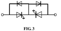
- FIG. 3 is a topological diagram of a fully-controlled device reverse-series switch according to an embodiment of the invention, and as shown in the figure, each fully-controlled device reverse-series switch in the embodiment includes two fully-controlled power electronic devices reversely connected in series, and each of the fully-controlled power electronic devices is reversely connected in parallel with a diode.
- FIG. 4 is a topological diagram of a fully-controlled device reverse-parallel switch according to an embodiment of the invention, and as shown in the figure, the fully-controlled reverse-parallel switch in the embodiment includes two fully-controlled power electronic devices reversely connected in parallel.
- FIG. 5 is a topological diagram of a first full-bridge switch according to an embodiment of the invention, and as shown in the figure, the first full-bridge switch in the embodiment includes a full-bridge structure unit, its bridge arm includes a fully-controlled power electronic device, and its capacitor is connected in parallel with a first resistor.
- FIG. 6 is a topological diagram of a second full-bridge switch according to an embodiment of the invention, and as shown in the figure, the second full-bridge switch in the embodiment includes a full-bridge structure unit, its bridge arm includes a fully-controlled power electronic device, and its direct current capacitor is connected in series with the diode after being connected in parallel with a second resistor.
- FIG. 7 is a topological diagram of a diode bridge type switch according to an embodiment of the invention, and as shown in the figure, the diode bridge type switch in the embodiment includes a full-bridge structure unit, its bridge arm includes a diode, and its direct current capacitor is connected in parallel with the fully-controlled power electronic device.
- the invention provides two implementation solutions of the novel combined direct current circuit breaker, herein
- FIG. 8 is a schematic diagram of an implementation solution of a novel combined direct current circuit breaker according to an embodiment of the invention, and as shown in the figure, in the embodiment, the power electronic switches in the primary branches, the secondary branches and the transfer branch all adopt fully-controlled device reverse-series switches.
- FIG. 9 is a schematic diagram of another implementation solution of a novel combined direct current circuit breaker according to an embodiment of the invention, and as shown in the figure, in the embodiment, the power electronic switches in the primary branch and the transfer branch all adopt second full-bridge switches, and the power electronic switches in the secondary branches adopt fully-controlled device reverse-series switches.
- the application method of the novel combined direct current circuit breaker in the invention is that: a working mode of the direct current circuit breaker is switched according to a running state of a high-voltage direct current power transmission system:
- the initial state of the direct current circuit breaker is that: the quick mechanical switches in all the primary branches are closed, the power electronic switches are turned on, the quick mechanical switches in all the secondary branches are closed, the power electronic switches are latched, and the power electronic switches in the transfer branch are latched; the direct current circuit breaker is switched into the third working mode by the following method:
- the novel combined direct current circuit breaker includes a transfer branch, an energy absorption branch, two primary branches (a primary branch 1 and a primary branch 2) and two secondary branches (a secondary branch 1 and a secondary branch 2), the primary branch 1 is connected with a direct current line 1, and the primary branch 2 is connected with a direct current line 2.
- the initial state of the direct current circuit breaker is that: the quick mechanical switches in the primary branch 1 and the primary branch 2 are closed, the power electronic switches are turned on, the quick mechanical switches in the secondary branch 1 and the secondary branch 2 are closed, the power electronic switches are latched, and the power electronic switches in the transfer branch are latched; and if an outlet of the converter station 1 has a grounding failure,
- FIG. 14 is a first state diagram when a direct current circuit breaker is in a third working mode according to an embodiment of the invention, and as shown in the figure, in the embodiment, the power electronic switches of the primary branch 1 and the primary branch 2 are latched, and the power electronic switches of the transfer branch, the secondary branch 1 and the secondary branch 2 are triggered to be turned on. After the failure current is totally transferred to the transfer branch, the secondary branch 1 and the secondary branch 2, the quick mechanical switches of the primary branch 1 and the primary branch 2 are broken.
- FIG. 15 is a second state diagram when a direct current circuit breaker is in a third working mode according to an embodiment of the invention. As shown in the figure, in the embodiment, after the breaking opening ranges of the quick mechanical switches withstand the transient breaking voltage, the power electronic switches of the transfer branch are latched, and the failure current of the converter station is transferred to the energy absorption branch.
- FIG. 16 is a third state diagram when a direct current circuit breaker is in a third working mode according to an embodiment of the invention. As shown in the figure, in the embodiment, after the failure current in the energy absorption branch crosses zero, the load current of the high-voltage direct current power transmission system is conducted through the secondary branch 1 and the secondary branch 2.
- the flow of the method of the embodiment may be implemented by instructing related hardware through a computer program, the program may be stored in a computer-readable storage medium, and when the program is executed, the flow of each abovementioned method embodiment may be included, herein the storage medium may be a magnetic disk, an optical disk, a Read-Only Memory (ROM), a Random Access Memory (RAM) or the like.
- the storage medium may be a magnetic disk, an optical disk, a Read-Only Memory (ROM), a Random Access Memory (RAM) or the like.
Landscapes
- Engineering & Computer Science (AREA)
- Power Engineering (AREA)
- Driving Mechanisms And Operating Circuits Of Arc-Extinguishing High-Tension Switches (AREA)
Claims (9)
- Neuartiger kombinierter Gleichstromschutzschalter, der in einem Hochspannungs-Gleichstromübertragungssystem benutzt wird, wobei eine Gleichstromsammelschiene wenigstens zwei Gleichstromabgangsleitungen hat, wobei der neuartige kombinierte Gleichstromschutzschalter einen Transferzweig, einen Energieabsorptionszweig, wenigstens zwei primäre Zweige und wenigstens zwei sekundäre Zweige umfasst,
wobei der Transferzweig parallel zum Energieabsorptionszweig geschaltet ist; dadurch gekennzeichnet, dass
jeder der wenigstens zwei primären Zweige mit einem jeweiligen einen der wenigstens zwei sekundären Zweige verbunden ist; jeder der primären Zweige mit einer jeweiligen einen der Gleichstromabgangsleitungen einer Gleichstromsammelschiene im Hochspannungs-Gleichstromübertragungssystem verbunden ist; und jeder der sekundären Zweige in Serie mit dem Transferzweig und einer durch den sekundären Zweig gebildeten resultierenden Schaltung verbunden ist und der Transferzweig parallel mit beiden Enden eines entsprechenden mit dem zweiten Zweig verbundenen primären Zweigs verbunden ist,
wobei eine Anzahl von primären Zweigen gleich einer Anzahl der Gleichstromabgangsleitungen ist und die wenigstens zwei primären Zweige den Transferzweig und den Energieabsorptionszweig gemeinsam nutzen. - Neuartiger kombinierter Gleichstromschutzschalter nach Anspruch 1, wobei
jeder primäre Zweig wenigstens einen schnellen mechanischen Schalter und wenigstens einen elektronischen Leistungsschalter in Serie geschaltet umfasst und zum Leiten eines Laststroms ausgelegt ist, wenn das Hochspannungs-Gleichstromübertragungssystem normal läuft;
jeder sekundäre Zweig wenigstens einen schnellen mechanischen Schalter und wenigstens einen elektronischen Leistungsschalter in Serie geschaltet umfasst und zum Isolieren eines Stroms und einer Spannung zwischen den Gleichstromabgangsleitungen ausgelegt ist;
der Transferzweig mehrere elektronische Leistungsschalter in Serie geschaltet umfasst und zum Unterbrechen eines Fehlerstroms ausgelegt ist, wenn die Gleichstromabgangsleitung oder die Gleichstromsammelschiene oder die Gleichstromkonverterstation in Verbindung mit einem beliebigen primären Zweig ausfällt; und
der Energieabsorptionszweig einen nichtlinearen Widerstand oder einen Blitzableiter umfasst und zum Unterbrechen einer Überspannung und zum Absorbieren von von einem induktiven Bauelement in dem Hochspannungs-Gleichstromübertragungssystem gespeicherten Energie ausgelegt ist, wenn die Gleichstromabgangsleitung oder Gleichstromsammelschiene oder Gleichstromkonverterstation in Verbindung mit einem beliebigen primären Zweig ausfällt. - Neuartiger kombinierter Gleichstromschutzschalter nach Anspruch 2, wobei
die mechanischen Schalter serielle mechanische Mehrfach-Unterbrechungsschalter oder parallele mechanische Mehrfach-Unterbrechungsschalter umfassen; wobei die seriellen mechanischen Mehrfach-Unterbrechungsschalter mehrere in Serie geschaltete Schalter umfassen und die parallelen mechanischen Mehrzweigschalter mehrere parallel geschaltete Schalter umfassen; und
die elektronischen Leistungsschalter bidirektionale Ein/Aus-Schalter sind. - Neuartiger kombinierter Gleichstromschutzschalter nach Anspruch 2, wobei
die elektronischen Leistungsschalter vollgesteuerte Rückwärts-Serien-Geräteschalter, vollgesteuerte Rückwärts-Parallel-Geräteschalter, erste Vollbrückenschalter, zweite Vollbrückenschalter und Schalter des Diodenbrückentyps umfassen;
jeder vollgesteuerte Rückwärts-Serien-Geräteschalter zwei rückwärts in Serie geschaltete, vollgesteuerte elektronische Leistungsgeräte umfasst und jedes der vollgesteuerten elektronischen Leistungsgeräte rückwärts parallel mit einer Diode geschaltet ist;
jeder vollgesteuerte rückwärts parallel geschaltete Schalter zwei rückwärts parallel geschaltete, vollgesteuerte elektronische Leistungsgeräte umfasst;
jeder erste Vollbrückenschalter eine Vollbrückenstruktureinheit umfasst, sein Brückenarm ein weiteres vollgesteuertes elektronisches Leistungsgerät umfasst und sein Kondensator mit einem ersten Widerstand parallel geschaltet ist;
jeder zweite Vollbrückenschalter eine Vollbrückenstruktureinheit umfasst, sein Brückenarm das weitere vollgesteuerte elektronische Leistungsgerät umfasst und sein Gleichstromkondensator parallel zu einem zweiten Widerstand geschaltet ist, und eine durch den Gleichstromkondensator und den zweiten Widerstand gebildete resultierende Schaltung in Serie mit der Diode geschaltet ist; und
jeder Schalter des Diodenbrückentyps eine Vollbrückenstruktureinheit umfasst, sein Brückenarm eine Diode umfasst und sein Gleichstromkondensator mit dem weiteren vollgesteuerten elektronischen Leistungsgerät parallel geschaltet ist. - Verfahren zum Anwenden des neuartigen kombinierten Gleichstromschutzschalters nach Anspruch 1-4, das das Schalten eines Arbeitsmodus des Gleichstromschutzschalters gemäß einem Laufzustand eines Hochspannungs-Gleichstromübertragungssystems auf die folgende Weise beinhaltet:Schalten des Gleichstromschutzschalters in einen ersten Arbeitsmodus, wenn das Hochspannungs-Gleichstromübertragungssystem normal läuft;Schalten des Gleichstromschutzschalters in einen zweiten Arbeitsmodus, wenn das Hochspannungs-Gleichstromübertragungssystem einen Leitungsausfall hat; undSchalten des Gleichstromschutzschalters in einen dritten Arbeitsmodus, wenn das Hochspannungs-Gleichstromübertragungssystem einen Konverterstations-Auslassausfall hat.
- Verfahren zum Anwenden eines neuartigen kombinierten Gleichstromschutzschalters nach Anspruch 5, wobei
das Schalten des Gleichstromschutzschalters in den ersten Arbeitsmodus Folgendes beinhaltet:Schließen von schnellen mechanischen Schaltern aller primären Zweige und Auslösen des Einschaltens von elektronischen Leistungsschaltern aller primären Zweige;Schließen von schnellen mechanischen Schaltern aller sekundären Zweige und Einrasten von elektronischen Leistungsschaltern aller sekundären Zweige; undEinrasten von elektronischen Leistungsschaltern eines Transferzweigs. - Verfahren zum Anwenden des neuartigen kombinierten Gleichstromschutzschalters nach Anspruch 6, wobei das Schalten des Gleichstromschutzschalters in den zweiten Arbeitsmodus Folgendes beinhaltet:in Schritt 11, Einrasten des elektronischen Leistungsschalters des mit einer Ausfallleitung verbundenen primären Zweigs, Auslösen des Einschaltens des elektronischen Leistungsschalters des mit dem primären Zweig verbundenen sekundären Zweigs, und Auslösen des Einschaltens der elektronischen Leistungsschalter des Transferzweigs;in Schritt 12, wenn ein Stromfluss durch den mit der Ausfallleitung in Schritt 11 verbundenen primären Zweig null überquert, Unterbrechen des schnellen mechanischen Schalters des primären Zweigs und Unterbrechen des schnellen mechanischen Schalters des nicht mit dem primären Zweig verbundenen sekundären Zweigs; undin Schritt 13, wenn offene Distanzen der schnellen mechanischen Schalter des primären Zweigs und des sekundären Zweigs in Schritt 12 eine transiente Unterbrechungsspannung aushalten, Einrasten der elektronischen Leistungsschalter des Transferzweigs, Übertragen eines Fehlerstroms der Ausfallleitung zu einer Energieabsorptionsschaltung, und wenn der Fehlerstrom in der Energieabsorptionsschaltung null überquert, Zurückführen des Hochspannungs-Gleichstromübertragungssystems auf Normallauf.
- Verfahren zum Anwenden des neuartigen kombinierten Gleichstromschutzschalters nach Anspruch 7, das nach dem Zurückführen des Hochspannungs-Gleichstromübertragungssystems auf Normallauf in Schritt 13 Folgendes beinhaltet:Steuern des Gleichstromschutzschalters zum Isolieren der Ausfallleitung, das Folgendes beinhaltet: Unterbrechen des schnellen mechanischen Schalters des sekundären Zweigs, der mit dem mit der Ausfallleitung verbundenen primären Zweig verbunden ist, Schließen der schnellen mechanischen Schalter der anderen sekundären Zweige und Zurückführen des Gleichstromschutzschalters in den Anfangszustand;oder,Steuern des Gleichstromschutzschalters zum schnellen Wiedereinschalten, das Folgendes beinhaltet:Auslösen des Einschaltens der elektronischen Leistungsschalter des Transferzweigs gemäß einer Wiedereinschaltanweisung, und wenn die Störung der Ausfallleitung fortbesteht, Einrasten der elektronischen Leistungsschalter und Isolieren der Ausfallleitung;Auslösen des Einschaltens der elektronischen Leistungsschalter des Transferzweigs gemäß der Wiedereinschaltanweisung, und wenn die Störung der Ausfallleitung eliminiert ist, Schließen des schnellen mechanischen Schalters des mit der Ausfallleitung verbundenen primären Zweigs, Auslösen des Einschaltens seines elektronischen Leistungsschalters, und Schließen der schnellen mechanischen Schalter der nicht mit dem primären Zweig verbundenen sekundären Zweige; und Einrasten, wenn ein Stromfluss durch den Transferzweig null überquert, der elektronischen Leistungsschalter des Transferzweigs und des mit dem primären Zweig verbundenen sekundären Zweigs, und Zurückführen des Gleichstromschutzschalters in den Anfangszustand.
- Verfahren zum Anwenden des neuartigen kombinierten Gleichstromschutzschalters nach Anspruch 7, wobei der Anfangszustand des Gleichstromschutzschalters wie folgt ist: die schnellen mechanischen Schalter in allen primären Zweigen sind geschlossen, die elektronischen Leistungsschalter sind eingeschaltet, die schnellen mechanischen Schalter in allen sekundären Zweigen sind geschlossen, die elektronischen Leistungsschalter sind eingerastet und die elektronischen Leistungsschalter im Transferzweig sind eingerastet;
wobei das Schalten des Betriebs des Gleichstromschutzschalters in den dritten Arbeitsmodus Folgendes beinhaltet:in Schritt 21, Einrasten der elektronischen Leistungsschalter aller primären Zweige und Auslösen des Einschaltens der elektronischen Leistungsschalter des Transferzweigs und aller sekundären Zweige;in Schritt 22, wenn ein Fehlerstrom eines Auslasses einer Konverterstation vollständig auf den Transferzweig und die sekundären Zweige übertragen ist, Unterbrechen der schnellen mechanischen Schalter aller primären Zweige; undin Schritt 23, wenn die offenen Distanzen der schnellen mechanischen Schalter die transiente Unterbrechungsspannung aushalten, Einrasten der elektronischen Leistungsschalter des Transferzweigs, Übertragen des Fehlerstroms auf die Energieabsorptionsschaltung und, wenn der Fehlerstrom in der Energieabsorptionsschaltung null überquert, Leiten eines Laststroms des Hochspannungs-Gleichstromübertragungssystems durch die sekundären Zweige.
Applications Claiming Priority (2)
| Application Number | Priority Date | Filing Date | Title |
|---|---|---|---|
| CN201610576055.6A CN107645154B (zh) | 2016-07-20 | 2016-07-20 | 一种新型组合式直流断路器及其应用方法 |
| PCT/CN2017/085281 WO2018014646A1 (zh) | 2016-07-20 | 2017-05-22 | 一种新型组合式直流断路器及其应用方法 |
Publications (3)
| Publication Number | Publication Date |
|---|---|
| EP3490091A1 EP3490091A1 (de) | 2019-05-29 |
| EP3490091A4 EP3490091A4 (de) | 2019-08-07 |
| EP3490091B1 true EP3490091B1 (de) | 2020-09-09 |
Family
ID=60991769
Family Applications (1)
| Application Number | Title | Priority Date | Filing Date |
|---|---|---|---|
| EP17830283.2A Active EP3490091B1 (de) | 2016-07-20 | 2017-05-22 | Neuartiger kombinierter gleichstromschutzschalter und anwendungsverfahren dafür |
Country Status (4)
| Country | Link |
|---|---|
| US (1) | US10756535B2 (de) |
| EP (1) | EP3490091B1 (de) |
| CN (1) | CN107645154B (de) |
| WO (1) | WO2018014646A1 (de) |
Families Citing this family (55)
| Publication number | Priority date | Publication date | Assignee | Title |
|---|---|---|---|---|
| CN107666140B (zh) * | 2017-09-01 | 2019-03-26 | 天津大学 | 一种具有多个接线端的组合式直流断路器及其控制方法 |
| CN109038510A (zh) * | 2018-07-25 | 2018-12-18 | 西安交通大学 | 一种直流断路器 |
| CN109217239B (zh) * | 2018-10-12 | 2020-07-24 | 南方电网科学研究院有限责任公司 | 一种具备选断功能的直流断路器 |
| CN109510178B (zh) * | 2018-10-22 | 2020-11-10 | 国网浙江省电力有限公司电力科学研究院 | 一种二极管钳位式多端口直流断路器及其动作时序 |
| CN109687405B (zh) * | 2018-11-20 | 2020-09-29 | 北京交通大学 | 一种多端口组合型混合式直流断路器及控制方法 |
| CN109327021A (zh) * | 2018-11-28 | 2019-02-12 | 天津大学 | 适用于多端柔性直流电网的经济型故障限流器及控制策略 |
| CN109802365B (zh) * | 2018-12-18 | 2023-04-14 | 华北电力大学 | 一种具备能量转移支路的多端口直流断路器及其控制方法 |
| CN109742739A (zh) * | 2018-12-18 | 2019-05-10 | 华北电力大学 | 一种新型多端口限流式直流断路器及其控制方法 |
| CN109687416A (zh) * | 2019-01-09 | 2019-04-26 | 天津大学 | 一种多端口经济型直流故障限流器 |
| CN109981092A (zh) * | 2019-01-14 | 2019-07-05 | 全球能源互联网研究院有限公司 | 一种全桥模块、全桥模块的混合式直流断路器及应用方法 |
| CN109687386B (zh) * | 2019-02-02 | 2020-03-06 | 四川大学 | 具有重合闸能力的混合式直流断路器缓冲支路 |
| CN109787200A (zh) * | 2019-02-20 | 2019-05-21 | 中国电力科学研究院有限公司 | 受端为lcc-vsc混联型的直流输电系统的断路器及其使用方法 |
| EP3949102A4 (de) * | 2019-03-27 | 2022-11-23 | Abb Schweiz Ag | Modularisierte dc-verbindungsvorrichtung und system dafür |
| CN109873407B (zh) * | 2019-03-28 | 2020-01-17 | 北京交通大学 | 一种环形桥式多端口混合直流断路器 |
| CN110112710A (zh) * | 2019-04-29 | 2019-08-09 | 四川大学 | 一种混合直流断路器及其保护方法 |
| CN110289603A (zh) * | 2019-06-14 | 2019-09-27 | 山东泰开高压开关有限公司 | 一种并联开断装置、主通支路及高压直流断路器 |
| CN110350650B (zh) * | 2019-07-05 | 2024-03-22 | 广西电网有限责任公司梧州供电局 | 大容量高可靠快速电源切换装置及其切换控制方法 |
| CN110460024B (zh) * | 2019-08-13 | 2024-05-10 | 国网浙江省电力有限公司电力科学研究院 | 一种直流电网潮流可控型多端口直流断路器及其控制方法 |
| CN112751323B (zh) * | 2019-10-31 | 2024-03-08 | 西安西电高压开关有限责任公司 | 一种直流断路器控制方法及直流断路器 |
| CN111243900A (zh) * | 2020-01-19 | 2020-06-05 | 国网江苏省电力有限公司电力科学研究院 | 一种液态六氟化硫弧压转移式直流断路器及其控制方法 |
| CN111509663A (zh) * | 2020-04-10 | 2020-08-07 | 中国南方电网有限责任公司超高压输电公司检修试验中心 | 一种二极管桥式多端口混合式直流断路器及其控制方法 |
| CN111509681A (zh) * | 2020-04-23 | 2020-08-07 | 广东电网有限责任公司东莞供电局 | 共用能耗支路的固态式直流断路器及其应用方法 |
| CN113809724B (zh) * | 2020-06-15 | 2023-10-20 | 许继集团有限公司 | 混合式高压直流断路器主支路电子开关保护方法及装置 |
| CN112039313B (zh) * | 2020-07-28 | 2022-02-18 | 漳州科华技术有限责任公司 | 辅助电源装置、辅助电源装置控制方法及变换器 |
| CN112086943B (zh) * | 2020-09-02 | 2022-05-24 | 东南大学 | 一种主动式故障限流电路及全固态直流断路器 |
| JP7458285B2 (ja) * | 2020-10-01 | 2024-03-29 | 東芝エネルギーシステムズ株式会社 | 直流電流遮断装置 |
| JP7467308B2 (ja) * | 2020-10-01 | 2024-04-15 | 株式会社東芝 | 直流電流遮断装置 |
| CN112332523A (zh) * | 2020-10-13 | 2021-02-05 | 广东电网有限责任公司 | 适用于直流电源可切换的直流断路器及其应用方法 |
| CN112290801B (zh) * | 2020-10-21 | 2021-08-03 | 哈尔滨工业大学 | 一种高升压比隔离型直流变换器及其控制方法 |
| CN112383134B (zh) * | 2020-11-23 | 2025-07-11 | 国家电网有限公司 | 一种双母线双转移支路组合式高压直流开关 |
| WO2022120562A1 (zh) * | 2020-12-08 | 2022-06-16 | 唐锋机电科技(深圳)有限公司 | 一种雾化片防氧化控制电路及方法 |
| CN112763900B (zh) * | 2020-12-25 | 2021-11-19 | 西安交通大学 | 一种混合式直流断路器耗能支路mov状态测量电路及方法 |
| CN112865061A (zh) * | 2021-01-07 | 2021-05-28 | 天津大学 | 基于电力电子器件的直流负荷开关及其投切方法 |
| CN112838576A (zh) * | 2021-02-07 | 2021-05-25 | 全球能源互联网研究院有限公司 | 一种直流断路器及其应用方法 |
| CN112865040A (zh) * | 2021-02-25 | 2021-05-28 | 全球能源互联网研究院有限公司 | 多端口直流断路器及其控制方法 |
| CN112865039B (zh) * | 2021-02-25 | 2025-08-05 | 全球能源互联网研究院有限公司 | 直流断路器及其控制方法 |
| CN112952776B (zh) * | 2021-03-02 | 2022-12-20 | 华北电力大学 | 一种适用于中压直流断路器的电流转移电路及方法 |
| CN112865047B (zh) * | 2021-03-05 | 2025-03-18 | 全球能源互联网研究院有限公司 | 一种多端口直流断路器及其应用方法 |
| CN112865044B (zh) * | 2021-03-05 | 2025-03-18 | 全球能源互联网研究院有限公司 | 一种电流注入式直流断路器及控制方法 |
| CN113257597A (zh) * | 2021-06-17 | 2021-08-13 | 清华大学 | 一种基于复合换流方式的混合式直流断路器及其控制方法 |
| CN113690862A (zh) * | 2021-08-23 | 2021-11-23 | 广东电网有限责任公司 | 一种消除柔性直流系统中过电压的装置及方法 |
| CN113972635B (zh) * | 2021-11-01 | 2024-02-06 | 中国长江三峡集团有限公司 | 一种四端口直流断路器控制方法 |
| CN114050556B (zh) * | 2021-11-02 | 2023-09-19 | 国网河北省电力有限公司雄安新区供电公司 | 一种基于电容换流和电感限流的高压直流断路器 |
| CN114050073B (zh) * | 2021-11-09 | 2024-07-05 | 许昌许继软件技术有限公司 | 一种直流开关装置及其控制方法 |
| CN114285014A (zh) * | 2022-01-05 | 2022-04-05 | 全球能源互联网研究院有限公司 | 一种直流断路器及其应用方法 |
| CN114597874A (zh) * | 2022-02-08 | 2022-06-07 | 中国长江三峡集团有限公司 | 基于转移支路复用的混合式多端口断路器及控制方法 |
| CN114597875A (zh) * | 2022-02-23 | 2022-06-07 | 中国长江三峡集团有限公司 | 一种双向多端口固态式直流断路器及其控制方法 |
| CN114825265A (zh) * | 2022-05-13 | 2022-07-29 | 国网浙江省电力有限公司电力科学研究院 | 一种具有双向阻断能力的多端直流断路器及其控制方法 |
| CN114825290B (zh) * | 2022-05-26 | 2024-12-24 | 国网安徽省电力有限公司阜阳供电公司 | 一种低成本电力电子式交流无弧断路系统及其控制方法 |
| CN115148519A (zh) * | 2022-06-13 | 2022-10-04 | 西安交通大学 | 一种基于自能式磁场吹弧实现转移的直流断路器 |
| CN115241850B (zh) * | 2022-07-01 | 2024-02-23 | 国网安徽省电力有限公司电力科学研究院 | 一种组合式高压直流断路器及其控制策略 |
| CN115085165A (zh) * | 2022-07-27 | 2022-09-20 | 国网冀北电力有限公司电力科学研究院 | 一种直流断路器及直流断路器的扩建方法 |
| JP2024027980A (ja) * | 2022-08-19 | 2024-03-01 | 学校法人大阪産業大学 | 遮断器 |
| US12573567B2 (en) | 2023-09-26 | 2026-03-10 | Siemens Industry, Inc. | Semiconductor-based DC transfer switch |
| CN118713015A (zh) * | 2024-04-17 | 2024-09-27 | 国网山西省电力公司电力科学研究院 | 一种基于熔断器的混合式多端口断路器及控制方法 |
Family Cites Families (15)
| Publication number | Priority date | Publication date | Assignee | Title |
|---|---|---|---|---|
| EP2777115B1 (de) * | 2011-11-11 | 2016-01-27 | ABB Technology AG | Verwendung des transferschalters eines hybridleistungsschalters als wahlschalter |
| FR2985082B1 (fr) * | 2011-12-23 | 2014-02-21 | Alstom Technology Ltd | Dispositif disjoncteur mecatronique et procede de declenchement associe et application a la coupure de courant continu eleve |
| CN103219699B (zh) | 2013-02-06 | 2015-04-22 | 西安交通大学 | 一种高压混合式直流断路器 |
| EP2768102B1 (de) * | 2013-02-13 | 2016-02-10 | General Electric Technology GmbH | Stromkreisunterbrechungsvorrichtung |
| CN103280763B (zh) | 2013-02-27 | 2016-12-28 | 国网智能电网研究院 | 一种直流断路器及其实现方法 |
| CN103441490B (zh) * | 2013-08-16 | 2016-08-10 | 国家电网公司 | 一种多端直流系统用直流断路器及其控制方法 |
| CN104979795B (zh) | 2014-04-08 | 2018-10-09 | 国家电网公司 | 一种无源型高压直流断路器及其实现方法 |
| CN104158171B (zh) * | 2014-08-18 | 2017-06-06 | 国家电网公司 | 一种高压直流断路器拓扑电路 |
| KR101630093B1 (ko) * | 2014-12-29 | 2016-06-13 | 주식회사 효성 | 고전압 dc 차단기 |
| CN107210604B (zh) * | 2015-01-30 | 2020-03-03 | Abb瑞士股份有限公司 | 用于互连直流电力网络的可缩放开关站 |
| CN104900444B (zh) * | 2015-06-26 | 2017-08-04 | 华北电力大学 | 直流断路器的拓扑结构及其控制方法 |
| CN105262068A (zh) * | 2015-10-14 | 2016-01-20 | 南京南瑞继保电气有限公司 | 一种高压直流断路器及其控制方法 |
| CN105552827B (zh) * | 2015-12-10 | 2018-08-14 | 西安交通大学 | 强制电流转移电路及其电流转移方法 |
| CN105656019B (zh) * | 2016-01-26 | 2019-06-28 | 华中科技大学 | 一种电容充电型直流断路器及其应用 |
| CN105655966A (zh) * | 2016-03-15 | 2016-06-08 | 许继电气股份有限公司 | 一种直流断路器 |
-
2016
- 2016-07-20 CN CN201610576055.6A patent/CN107645154B/zh active Active
-
2017
- 2017-05-22 EP EP17830283.2A patent/EP3490091B1/de active Active
- 2017-05-22 US US16/067,602 patent/US10756535B2/en active Active
- 2017-05-22 WO PCT/CN2017/085281 patent/WO2018014646A1/zh not_active Ceased
Non-Patent Citations (1)
| Title |
|---|
| None * |
Also Published As
| Publication number | Publication date |
|---|---|
| CN107645154B (zh) | 2020-03-06 |
| US10756535B2 (en) | 2020-08-25 |
| US20190006838A1 (en) | 2019-01-03 |
| EP3490091A1 (de) | 2019-05-29 |
| EP3490091A4 (de) | 2019-08-07 |
| WO2018014646A1 (zh) | 2018-01-25 |
| CN107645154A (zh) | 2018-01-30 |
Similar Documents
| Publication | Publication Date | Title |
|---|---|---|
| EP3490091B1 (de) | Neuartiger kombinierter gleichstromschutzschalter und anwendungsverfahren dafür | |
| CN104242265B (zh) | 一种直流配电网全固态直流断路器 | |
| CN103474983B (zh) | 一种高压大电流直流断路器及其控制方法 | |
| Li et al. | An auxiliary DC circuit breaker utilizing an augmented MMC | |
| CN103972855A (zh) | 一种使线路双向电流分断的装置及其控制方法 | |
| CN110970875A (zh) | 一种用于直流电网的组合限流型直流断路器 | |
| CN104753044A (zh) | 一种混合式全固态高压直流断路器拓扑结构 | |
| CN106206208A (zh) | 大功率双向开断的混合式直流断路器 | |
| CN103457257A (zh) | 一种多端直流系统用直流断路器及其控制方法 | |
| CN109494693A (zh) | 一种降低重合闸冲击的混合式直流断路器及控制方法 | |
| CN106786349A (zh) | 一种辅助换流模块及高压直流断路器 | |
| CN107370130B (zh) | 一种基于改进型半桥子模块的混合式高压直流断路器及其控制策略 | |
| CN115241850B (zh) | 一种组合式高压直流断路器及其控制策略 | |
| CN114172135A (zh) | 一种适用于多端直流电网的双主断型多端口混合直流断路器 | |
| CN103457258B (zh) | 一种多端直流系统用直流断路器及其控制方法 | |
| CN113644636B (zh) | 基于电容换相的多端混合式高压直流断路器 | |
| CN112865046B (zh) | 一种多功能多端口混合式直流断路器及控制方法 | |
| CN106533145B (zh) | 一种高压直流断路器 | |
| CN112865044A (zh) | 一种电流注入式直流断路器及控制方法 | |
| CN112838576A (zh) | 一种直流断路器及其应用方法 | |
| CN106655119A (zh) | 一种用于清除交直流系统故障电流的电路及其控制方法 | |
| Ding et al. | Overview of topology research on hybrid direct current circuit breakers | |
| CN207603201U (zh) | 一种短路故障限流器 | |
| CN214314552U (zh) | 一种多功能多端口混合式直流断路器 | |
| CN207426678U (zh) | 一种混合式直流断路器及直流输配电系统的电路拓扑结构 |
Legal Events
| Date | Code | Title | Description |
|---|---|---|---|
| STAA | Information on the status of an ep patent application or granted ep patent |
Free format text: STATUS: THE INTERNATIONAL PUBLICATION HAS BEEN MADE |
|
| PUAI | Public reference made under article 153(3) epc to a published international application that has entered the european phase |
Free format text: ORIGINAL CODE: 0009012 |
|
| STAA | Information on the status of an ep patent application or granted ep patent |
Free format text: STATUS: REQUEST FOR EXAMINATION WAS MADE |
|
| 17P | Request for examination filed |
Effective date: 20180418 |
|
| AK | Designated contracting states |
Kind code of ref document: A1 Designated state(s): AL AT BE BG CH CY CZ DE DK EE ES FI FR GB GR HR HU IE IS IT LI LT LU LV MC MK MT NL NO PL PT RO RS SE SI SK SM TR |
|
| AX | Request for extension of the european patent |
Extension state: BA ME |
|
| A4 | Supplementary search report drawn up and despatched |
Effective date: 20190708 |
|
| RIC1 | Information provided on ipc code assigned before grant |
Ipc: H02J 3/36 20060101ALN20190702BHEP Ipc: H02H 7/26 20060101AFI20190702BHEP |
|
| DAV | Request for validation of the european patent (deleted) | ||
| DAX | Request for extension of the european patent (deleted) | ||
| GRAP | Despatch of communication of intention to grant a patent |
Free format text: ORIGINAL CODE: EPIDOSNIGR1 |
|
| STAA | Information on the status of an ep patent application or granted ep patent |
Free format text: STATUS: GRANT OF PATENT IS INTENDED |
|
| RIC1 | Information provided on ipc code assigned before grant |
Ipc: H02J 3/36 20060101ALN20200401BHEP Ipc: H02H 7/26 20060101AFI20200401BHEP Ipc: H02H 3/087 20060101ALI20200401BHEP |
|
| INTG | Intention to grant announced |
Effective date: 20200415 |
|
| GRAS | Grant fee paid |
Free format text: ORIGINAL CODE: EPIDOSNIGR3 |
|
| GRAA | (expected) grant |
Free format text: ORIGINAL CODE: 0009210 |
|
| STAA | Information on the status of an ep patent application or granted ep patent |
Free format text: STATUS: THE PATENT HAS BEEN GRANTED |
|
| AK | Designated contracting states |
Kind code of ref document: B1 Designated state(s): AL AT BE BG CH CY CZ DE DK EE ES FI FR GB GR HR HU IE IS IT LI LT LU LV MC MK MT NL NO PL PT RO RS SE SI SK SM TR |
|
| REG | Reference to a national code |
Ref country code: GB Ref legal event code: FG4D |
|
| REG | Reference to a national code |
Ref country code: AT Ref legal event code: REF Ref document number: 1312758 Country of ref document: AT Kind code of ref document: T Effective date: 20200915 Ref country code: CH Ref legal event code: EP |
|
| REG | Reference to a national code |
Ref country code: IE Ref legal event code: FG4D |
|
| REG | Reference to a national code |
Ref country code: DE Ref legal event code: R096 Ref document number: 602017023522 Country of ref document: DE |
|
| REG | Reference to a national code |
Ref country code: LT Ref legal event code: MG4D |
|
| REG | Reference to a national code |
Ref country code: DE Ref legal event code: R082 Ref document number: 602017023522 Country of ref document: DE Representative=s name: MATHYS & SQUIRE GBR, DE Ref country code: DE Ref legal event code: R082 Ref document number: 602017023522 Country of ref document: DE Representative=s name: MATHYS & SQUIRE EUROPE PATENTANWAELTE PARTNERS, DE |
|
| PG25 | Lapsed in a contracting state [announced via postgrant information from national office to epo] |
Ref country code: GR Free format text: LAPSE BECAUSE OF FAILURE TO SUBMIT A TRANSLATION OF THE DESCRIPTION OR TO PAY THE FEE WITHIN THE PRESCRIBED TIME-LIMIT Effective date: 20201210 Ref country code: LT Free format text: LAPSE BECAUSE OF FAILURE TO SUBMIT A TRANSLATION OF THE DESCRIPTION OR TO PAY THE FEE WITHIN THE PRESCRIBED TIME-LIMIT Effective date: 20200909 Ref country code: BG Free format text: LAPSE BECAUSE OF FAILURE TO SUBMIT A TRANSLATION OF THE DESCRIPTION OR TO PAY THE FEE WITHIN THE PRESCRIBED TIME-LIMIT Effective date: 20201209 Ref country code: SE Free format text: LAPSE BECAUSE OF FAILURE TO SUBMIT A TRANSLATION OF THE DESCRIPTION OR TO PAY THE FEE WITHIN THE PRESCRIBED TIME-LIMIT Effective date: 20200909 Ref country code: NO Free format text: LAPSE BECAUSE OF FAILURE TO SUBMIT A TRANSLATION OF THE DESCRIPTION OR TO PAY THE FEE WITHIN THE PRESCRIBED TIME-LIMIT Effective date: 20201209 Ref country code: HR Free format text: LAPSE BECAUSE OF FAILURE TO SUBMIT A TRANSLATION OF THE DESCRIPTION OR TO PAY THE FEE WITHIN THE PRESCRIBED TIME-LIMIT Effective date: 20200909 Ref country code: FI Free format text: LAPSE BECAUSE OF FAILURE TO SUBMIT A TRANSLATION OF THE DESCRIPTION OR TO PAY THE FEE WITHIN THE PRESCRIBED TIME-LIMIT Effective date: 20200909 |
|
| REG | Reference to a national code |
Ref country code: AT Ref legal event code: MK05 Ref document number: 1312758 Country of ref document: AT Kind code of ref document: T Effective date: 20200909 |
|
| REG | Reference to a national code |
Ref country code: NL Ref legal event code: MP Effective date: 20200909 |
|
| PG25 | Lapsed in a contracting state [announced via postgrant information from national office to epo] |
Ref country code: RS Free format text: LAPSE BECAUSE OF FAILURE TO SUBMIT A TRANSLATION OF THE DESCRIPTION OR TO PAY THE FEE WITHIN THE PRESCRIBED TIME-LIMIT Effective date: 20200909 Ref country code: LV Free format text: LAPSE BECAUSE OF FAILURE TO SUBMIT A TRANSLATION OF THE DESCRIPTION OR TO PAY THE FEE WITHIN THE PRESCRIBED TIME-LIMIT Effective date: 20200909 Ref country code: PL Free format text: LAPSE BECAUSE OF FAILURE TO SUBMIT A TRANSLATION OF THE DESCRIPTION OR TO PAY THE FEE WITHIN THE PRESCRIBED TIME-LIMIT Effective date: 20200909 |
|
| PG25 | Lapsed in a contracting state [announced via postgrant information from national office to epo] |
Ref country code: SM Free format text: LAPSE BECAUSE OF FAILURE TO SUBMIT A TRANSLATION OF THE DESCRIPTION OR TO PAY THE FEE WITHIN THE PRESCRIBED TIME-LIMIT Effective date: 20200909 Ref country code: EE Free format text: LAPSE BECAUSE OF FAILURE TO SUBMIT A TRANSLATION OF THE DESCRIPTION OR TO PAY THE FEE WITHIN THE PRESCRIBED TIME-LIMIT Effective date: 20200909 Ref country code: RO Free format text: LAPSE BECAUSE OF FAILURE TO SUBMIT A TRANSLATION OF THE DESCRIPTION OR TO PAY THE FEE WITHIN THE PRESCRIBED TIME-LIMIT Effective date: 20200909 Ref country code: PT Free format text: LAPSE BECAUSE OF FAILURE TO SUBMIT A TRANSLATION OF THE DESCRIPTION OR TO PAY THE FEE WITHIN THE PRESCRIBED TIME-LIMIT Effective date: 20210111 Ref country code: CZ Free format text: LAPSE BECAUSE OF FAILURE TO SUBMIT A TRANSLATION OF THE DESCRIPTION OR TO PAY THE FEE WITHIN THE PRESCRIBED TIME-LIMIT Effective date: 20200909 |
|
| PG25 | Lapsed in a contracting state [announced via postgrant information from national office to epo] |
Ref country code: IS Free format text: LAPSE BECAUSE OF FAILURE TO SUBMIT A TRANSLATION OF THE DESCRIPTION OR TO PAY THE FEE WITHIN THE PRESCRIBED TIME-LIMIT Effective date: 20210109 Ref country code: AT Free format text: LAPSE BECAUSE OF FAILURE TO SUBMIT A TRANSLATION OF THE DESCRIPTION OR TO PAY THE FEE WITHIN THE PRESCRIBED TIME-LIMIT Effective date: 20200909 Ref country code: AL Free format text: LAPSE BECAUSE OF FAILURE TO SUBMIT A TRANSLATION OF THE DESCRIPTION OR TO PAY THE FEE WITHIN THE PRESCRIBED TIME-LIMIT Effective date: 20200909 Ref country code: ES Free format text: LAPSE BECAUSE OF FAILURE TO SUBMIT A TRANSLATION OF THE DESCRIPTION OR TO PAY THE FEE WITHIN THE PRESCRIBED TIME-LIMIT Effective date: 20200909 |
|
| REG | Reference to a national code |
Ref country code: DE Ref legal event code: R097 Ref document number: 602017023522 Country of ref document: DE |
|
| PG25 | Lapsed in a contracting state [announced via postgrant information from national office to epo] |
Ref country code: SK Free format text: LAPSE BECAUSE OF FAILURE TO SUBMIT A TRANSLATION OF THE DESCRIPTION OR TO PAY THE FEE WITHIN THE PRESCRIBED TIME-LIMIT Effective date: 20200909 |
|
| PLBE | No opposition filed within time limit |
Free format text: ORIGINAL CODE: 0009261 |
|
| STAA | Information on the status of an ep patent application or granted ep patent |
Free format text: STATUS: NO OPPOSITION FILED WITHIN TIME LIMIT |
|
| 26N | No opposition filed |
Effective date: 20210610 |
|
| PG25 | Lapsed in a contracting state [announced via postgrant information from national office to epo] |
Ref country code: DK Free format text: LAPSE BECAUSE OF FAILURE TO SUBMIT A TRANSLATION OF THE DESCRIPTION OR TO PAY THE FEE WITHIN THE PRESCRIBED TIME-LIMIT Effective date: 20200909 Ref country code: SI Free format text: LAPSE BECAUSE OF FAILURE TO SUBMIT A TRANSLATION OF THE DESCRIPTION OR TO PAY THE FEE WITHIN THE PRESCRIBED TIME-LIMIT Effective date: 20200909 |
|
| PG25 | Lapsed in a contracting state [announced via postgrant information from national office to epo] |
Ref country code: IT Free format text: LAPSE BECAUSE OF FAILURE TO SUBMIT A TRANSLATION OF THE DESCRIPTION OR TO PAY THE FEE WITHIN THE PRESCRIBED TIME-LIMIT Effective date: 20200909 |
|
| REG | Reference to a national code |
Ref country code: CH Ref legal event code: PL |
|
| PG25 | Lapsed in a contracting state [announced via postgrant information from national office to epo] |
Ref country code: MC Free format text: LAPSE BECAUSE OF FAILURE TO SUBMIT A TRANSLATION OF THE DESCRIPTION OR TO PAY THE FEE WITHIN THE PRESCRIBED TIME-LIMIT Effective date: 20200909 Ref country code: LU Free format text: LAPSE BECAUSE OF NON-PAYMENT OF DUE FEES Effective date: 20210522 Ref country code: LI Free format text: LAPSE BECAUSE OF NON-PAYMENT OF DUE FEES Effective date: 20210531 Ref country code: CH Free format text: LAPSE BECAUSE OF NON-PAYMENT OF DUE FEES Effective date: 20210531 |
|
| REG | Reference to a national code |
Ref country code: BE Ref legal event code: MM Effective date: 20210531 |
|
| PG25 | Lapsed in a contracting state [announced via postgrant information from national office to epo] |
Ref country code: IE Free format text: LAPSE BECAUSE OF NON-PAYMENT OF DUE FEES Effective date: 20210522 |
|
| PG25 | Lapsed in a contracting state [announced via postgrant information from national office to epo] |
Ref country code: FR Free format text: LAPSE BECAUSE OF NON-PAYMENT OF DUE FEES Effective date: 20210531 |
|
| PG25 | Lapsed in a contracting state [announced via postgrant information from national office to epo] |
Ref country code: BE Free format text: LAPSE BECAUSE OF NON-PAYMENT OF DUE FEES Effective date: 20210531 |
|
| PG25 | Lapsed in a contracting state [announced via postgrant information from national office to epo] |
Ref country code: NL Free format text: LAPSE BECAUSE OF NON-PAYMENT OF DUE FEES Effective date: 20200923 Ref country code: CY Free format text: LAPSE BECAUSE OF FAILURE TO SUBMIT A TRANSLATION OF THE DESCRIPTION OR TO PAY THE FEE WITHIN THE PRESCRIBED TIME-LIMIT Effective date: 20200909 |
|
| PG25 | Lapsed in a contracting state [announced via postgrant information from national office to epo] |
Ref country code: HU Free format text: LAPSE BECAUSE OF FAILURE TO SUBMIT A TRANSLATION OF THE DESCRIPTION OR TO PAY THE FEE WITHIN THE PRESCRIBED TIME-LIMIT; INVALID AB INITIO Effective date: 20170522 |
|
| PG25 | Lapsed in a contracting state [announced via postgrant information from national office to epo] |
Ref country code: MK Free format text: LAPSE BECAUSE OF FAILURE TO SUBMIT A TRANSLATION OF THE DESCRIPTION OR TO PAY THE FEE WITHIN THE PRESCRIBED TIME-LIMIT Effective date: 20200909 |
|
| PG25 | Lapsed in a contracting state [announced via postgrant information from national office to epo] |
Ref country code: MT Free format text: LAPSE BECAUSE OF FAILURE TO SUBMIT A TRANSLATION OF THE DESCRIPTION OR TO PAY THE FEE WITHIN THE PRESCRIBED TIME-LIMIT Effective date: 20200909 |
|
| PGFP | Annual fee paid to national office [announced via postgrant information from national office to epo] |
Ref country code: DE Payment date: 20250618 Year of fee payment: 9 |
|
| PG25 | Lapsed in a contracting state [announced via postgrant information from national office to epo] |
Ref country code: TR Free format text: LAPSE BECAUSE OF FAILURE TO SUBMIT A TRANSLATION OF THE DESCRIPTION OR TO PAY THE FEE WITHIN THE PRESCRIBED TIME-LIMIT Effective date: 20200909 |
|
| PGFP | Annual fee paid to national office [announced via postgrant information from national office to epo] |
Ref country code: GB Payment date: 20260331 Year of fee payment: 10 |