EP3489899A1 - Image processing device and image processing method - Google Patents
Image processing device and image processing method Download PDFInfo
- Publication number
- EP3489899A1 EP3489899A1 EP17831115.5A EP17831115A EP3489899A1 EP 3489899 A1 EP3489899 A1 EP 3489899A1 EP 17831115 A EP17831115 A EP 17831115A EP 3489899 A1 EP3489899 A1 EP 3489899A1
- Authority
- EP
- European Patent Office
- Prior art keywords
- lane
- width
- captured image
- vehicle
- image processing
- Prior art date
- Legal status (The legal status is an assumption and is not a legal conclusion. Google has not performed a legal analysis and makes no representation as to the accuracy of the status listed.)
- Granted
Links
Images


Classifications
-
- G—PHYSICS
- G06—COMPUTING OR CALCULATING; COUNTING
- G06T—IMAGE DATA PROCESSING OR GENERATION, IN GENERAL
- G06T7/00—Image analysis
- G06T7/80—Analysis of captured images to determine intrinsic or extrinsic camera parameters, i.e. camera calibration
-
- B—PERFORMING OPERATIONS; TRANSPORTING
- B60—VEHICLES IN GENERAL
- B60W—CONJOINT CONTROL OF VEHICLE SUB-UNITS OF DIFFERENT TYPE OR DIFFERENT FUNCTION; CONTROL SYSTEMS SPECIALLY ADAPTED FOR HYBRID VEHICLES; ROAD VEHICLE DRIVE CONTROL SYSTEMS FOR PURPOSES NOT RELATED TO THE CONTROL OF A PARTICULAR SUB-UNIT
- B60W40/00—Estimation or calculation of non-directly measurable driving parameters for road vehicle drive control systems not related to the control of a particular sub unit, e.g. by using mathematical models
- B60W40/02—Estimation or calculation of non-directly measurable driving parameters for road vehicle drive control systems not related to the control of a particular sub unit, e.g. by using mathematical models related to ambient conditions
- B60W40/04—Traffic conditions
-
- B—PERFORMING OPERATIONS; TRANSPORTING
- B60—VEHICLES IN GENERAL
- B60W—CONJOINT CONTROL OF VEHICLE SUB-UNITS OF DIFFERENT TYPE OR DIFFERENT FUNCTION; CONTROL SYSTEMS SPECIALLY ADAPTED FOR HYBRID VEHICLES; ROAD VEHICLE DRIVE CONTROL SYSTEMS FOR PURPOSES NOT RELATED TO THE CONTROL OF A PARTICULAR SUB-UNIT
- B60W40/00—Estimation or calculation of non-directly measurable driving parameters for road vehicle drive control systems not related to the control of a particular sub unit, e.g. by using mathematical models
- B60W40/10—Estimation or calculation of non-directly measurable driving parameters for road vehicle drive control systems not related to the control of a particular sub unit, e.g. by using mathematical models related to vehicle motion
- B60W40/11—Pitch movement
-
- G—PHYSICS
- G06—COMPUTING OR CALCULATING; COUNTING
- G06V—IMAGE OR VIDEO RECOGNITION OR UNDERSTANDING
- G06V20/00—Scenes; Scene-specific elements
- G06V20/50—Context or environment of the image
- G06V20/56—Context or environment of the image exterior to a vehicle by using sensors mounted on the vehicle
-
- G—PHYSICS
- G06—COMPUTING OR CALCULATING; COUNTING
- G06T—IMAGE DATA PROCESSING OR GENERATION, IN GENERAL
- G06T2207/00—Indexing scheme for image analysis or image enhancement
- G06T2207/10—Image acquisition modality
- G06T2207/10016—Video; Image sequence
-
- G—PHYSICS
- G06—COMPUTING OR CALCULATING; COUNTING
- G06T—IMAGE DATA PROCESSING OR GENERATION, IN GENERAL
- G06T2207/00—Indexing scheme for image analysis or image enhancement
- G06T2207/30—Subject of image; Context of image processing
- G06T2207/30248—Vehicle exterior or interior
- G06T2207/30252—Vehicle exterior; Vicinity of vehicle
- G06T2207/30256—Lane; Road marking
Definitions
- the present disclosure relates to an image processing device that corrects a deviation of a detected width of a lane, and an image processing method.
- Patent Literature 1 discloses a technique through which final road information is obtained based on a first road information obtained based on map information and a second road information obtained by using an imaging device.
- Patent Literature 1 JP-A-H11-211492
- the present disclosure provides a technique through which accuracy of road information acquired using a camera or the like is improved.
- an image processing device includes: a lane-width calculation unit, which calculates a width of a lane in which a vehicle travels from a captured image, in which a front of the vehicle in a traveling direction is captured, based on a correlation between a length of a subject in the captured image and a number of pixels constituting the captured image; a position information acquisition unit, which acquires information indicating a position of the vehicle; a lane-width acquisition unit, which acquires information indicating a width of the lane in which the vehicle travels based on the information indicating the position of the vehicle; and a scale correction unit, which corrects the correlation between the length of the subject in the captured image and the number of pixels constituting the captured image in a case where a difference between the width of the lane calculated by the lane-width calculation unit and the width of the lane acquired from the map data is greater than a predetermined value that serves as a criterion for correcting errors.
- the scale correction unit may correct the correlation between the length of the subject in the captured image and the number of pixels constituting the captured image in a case where the difference between the width of the lane calculated by the lane-width calculation unit and the width of the lane acquired by the lane-width acquisition unit is greater than the predetermined value for a period longer than a predetermined period.
- the predetermined value may be determined based on the width of the lane acquired by the lane-width acquisition unit and a width of the vehicle.
- the predetermined value may be determined to be small as a difference between the width of the lane acquired by the lane-width acquisition unit and the width of the vehicle becomes small.
- an image processing method includes: calculating a width of a lane in which a vehicle travels from a captured image, in which captures a front of the vehicle in a traveling direction, based on a correlation between a length of a subject in the captured image and a number of pixels constituting the captured image; acquiring information indicating a position of the vehicle; acquiring information indicating a width of the lane in which the vehicle travels based on the information indicating the position of the vehicle; and correcting the correlation between the length of the subject in the captured image and the number of pixels constituting the captured image in a case where a difference between the calculated width of the lane and the width of the lane acquired from the map data is greater than a predetermined value that serves as a criterion for correcting errors.
- the accuracy of road information acquired by using a camera or the like can be improved.
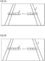
- FIGS. 1A and 1B are diagrams showing captured images in front of a vehicle in a traveling direction.
- FIGS. 1A and 1B depict pixels P and a traveling lane divided by dividing lines C.
- areas to be captured are different.
- a camera that captures the captured image of FIG. 1B is downwardly oriented than the camera that captures the captured image of FIG. 1A due to an influence of vibration or the like. Therefore, the captured image of FIG. 1A captures a farther side than the captured image of FIG. 1B .
- the image processing device calculates, for example, a size or length of a subject based on the number of pixels occupied by the subject in the captured image. As is seen from FIGS. 1A and 1B , the number of pixels corresponding to a lane width changes in a case where orientation of the camera is changed due to vibration or the like. As a result, the image processing device cannot calculate the correct lane width. In a case where the image processing device cannot calculate the correct lane width, for example, calculation accuracy of a curvature of a curve in which the vehicle travels is lowered, and the image processing device cannot effectively perform steering assistance during curve travel.
- the image processing device corrects a correlation between the length of the subject in the captured image and the number of pixels constituting the captured image. This makes it possible to improve accuracy of road information acquired by the vehicle using a camera or the like.
- a method of detecting a width of the lane is not limited to use of the camera as long as the width of the lane can be detected.
- the image processing device is described below with reference to FIG. 2 .
- FIG. 2 is a diagram showing a configuration of an image processing device 1 according to the embodiment.
- the image processing device 1 includes a storage unit 2, a control unit 3, a camera 4, and a global positioning system (GPS) sensor 5.
- the control unit 3 is, for example, an electronic control unit (ECU), and is connected to the storage unit 2 and the camera 4 in a wired or wireless manner.
- the camera 4 captures a road in front of the vehicle in the traveling direction.
- the GPS sensor 5 acquires position information on the vehicle.
- the storage unit 2 includes, for example, a Read Only Memory (ROM) in which a program executed by the control unit 3 is recorded and a Random Access Memory (RAM) that temporarily stores data.
- the ROM records map data including information on a width of a lane of a road on which the vehicle travels.
- the ROM also records magnitude of an error that serves as a criterion for correcting the correlation between the length of the subject in the captured image and the number of pixels constituting the captured image.
- the RAM records the corrected correlation between the length of the subject in the captured image and the number of pixels constituting the captured image.
- the RAM also records captured images captured by the camera 4.
- the storage unit 2 further may include a solid state drive (SSD), a hard disk drive (HDD), or the like, and the map data may be recorded in the SSD or the HDD.
- SSD solid state drive
- HDD hard disk drive
- the width of the lane can be calculated on a corrected scale even after an engine is stopped by recording the correlation between the length of the subject in the captured image and the number of pixels constituting the captured image in the same SSD or HDD after error correction.
- the control unit 3 functions as a lane-width calculation unit 6, a position information acquisition unit 7, a lane-width acquisition unit 8, and a scale correction unit 9 by executing the program stored in the storage unit 2.
- the lane-width calculation unit 6 acquires a captured image, in which a front of the vehicle in the traveling direction is captured, from the camera 4 and calculates a width of a lane in which the vehicle travels from the captured image. Specifically, for example, the lane-width calculation unit 6 counts the number of pixels present from a pixel on a dividing line to a pixel on another dividing line, as shown in FIG. 1 , and calculates the width of the lane based on a correlation between a predetermined number of pixels and a distance.
- the lane-width calculation unit 6 calculates the width of the lane as 3 m if there are 300 pixels between dividing lines in the captured image.
- the lane-width calculation unit 6 records the calculated width of the lane in the storage unit 2, and notifies the scale correction unit 9 of the width.
- the width of the lane may be arbitrarily defined.
- the lane-width calculation unit 6 may measure the lane width from outside of a dividing line having a thickness.
- the lane-width calculation unit 6 may measure the lane width from middle of a dividing line.
- the lane-width calculation unit 6 may measure the lane width from inside of a dividing line.
- a dividing line is detected, for example, based on a known method.
- the position information acquisition unit 7 acquires information indicating a position of the vehicle from the GPS sensor 5. After acquiring the information on the position of the vehicle, the position information acquisition unit 7 notifies the lane-width acquisition unit 8 of the acquired information.
- the lane-width acquisition unit 8 Based on the information indicating the position of the vehicle notified from the position information acquisition unit 7, the lane-width acquisition unit 8 acquires a width of the lane in which the vehicle travels from the map data recorded in the storage unit 2. The lane-width acquisition unit 8 records the width of the lane acquired from the map data in the storage unit 2 and notifies the scale correction unit 9 of the width.
- the scale correction unit 9 corrects a correlation between the length of the subject in the captured image and the number of pixels constituting the captured image.
- the predetermined value is, for example, the same as the thickness of the dividing line or 10 cm.
- the number of pixels present between dividing lines in FIG. 1B is 250, which corresponds to 1 cm per pixel.
- the lane-width calculation unit 6 calculates the width of the lane as 2.5 m. Meanwhile, in a case where the width of the lane acquired by the lane-width acquisition unit 8 from the map data is 3 m, an error between the width of the lane calculated by the lane-width calculation unit 6 and the width of the lane acquired by the position information acquisition unit 7 is 50 cm.
- the scale correction unit 9 corrects the correlation between the length of the subject in the captured image and the number of pixels constituting the captured image. In this case, the scale correction unit 9 corrects the correlation between the length of the subject in the captured image and the number of pixels constituting the captured image assuming, for example, 1.2 cm per pixel, and records the correlation in the storage unit 2.
- the predetermined value may be determined based on the width of the lane acquired by the lane-width acquisition unit 8 and a vehicle width. For example, the predetermined value may be small as a difference between the width of the lane acquired by the lane-width acquisition unit 8 and the vehicle width becomes small.
- the vehicle is likely to get out of the lane in a case where the difference between the width of the lane and the vehicle width is small. Therefore, in a case where the difference between the width of the lane and the vehicle width is small, the correlation between the length of the subject in the captured image and the number of pixels constituting the captured image is corrected even if the difference between the width of the lane calculated by the lane-width calculation unit 6 and the width of the lane acquired by the lane-width acquisition unit 8 from the map data is small. Accordingly, the image processing device 1 can detect the width of the lane with high accuracy and perform lane maintaining assistance more effectively.
- the predetermined value may be increased as the difference between the width of the lane acquired by the lane-width acquisition unit 8 and the vehicle width becomes large.
- the correlation between the length of the subject in the captured image and the number of pixels constituting the captured image is not corrected in a case where the difference between the width of the lane calculated by the lane-width calculation unit 6 and the width of the lane acquired by the lane-width acquisition unit 8 from the map data is small. Accordingly, chances that the scale correction unit 9 corrects the correlation between the length of the subject in the captured image and the number of pixels constituting the captured image are reduced. As a result, driving experience is improved since a driver enjoys the lane maintaining assistance that performs the same operation over a long period.
- the predetermined value may also be changed according to the thickness of the dividing line detected from the captured image.
- the predetermined value may be small as the dividing line is thin. In a case where the dividing line is thin, chances that the vehicle gets over the dividing line, that is, gets over the lane, increases. Therefore, in a case where the dividing line is thin, the image processing device 1 can effectively perform the lane maintaining assistance by correcting the correlation between the length of the subject in the captured image and the number of pixels constituting the captured image even in a case where the error is small.
- the scale correction unit 9 may correct the correlation between the length of the subject in the captured image and the number of pixels constituting the captured image. This is described with reference to FIG. 3 .
- FIG. 3 is a diagram in which widths of a lane calculated by the lane-width calculation unit 6 at each time point are plotted.
- a vertical axis indicates a width of the lane
- a horizontal axis indicates time.
- the width of the lane acquired by the lane-width acquisition unit 8 from the map data is represented by a solid line
- the predetermined value indicating an allowable error is represented by a width of the solid line and broken lines in FIG. 3 .
- the scale correction unit 9 corrects the correlation between the length of the subject in the captured image and the number of pixels constituting the captured image.
- the predetermined period is longer than a period considered for the vehicle to pass through a distorted place of the traveling road, for example, 5 seconds.
- the scale correction unit 9 does not correct the correlation between the length of the subject in the captured image and the number of pixels constituting the captured image, for example, in a case where the vehicle temporarily passes through a place where the road has deteriorated and the diving line deviates from an initially laid position. Therefore, it is possible to prevent the correlation between the length of the subject in the captured image and the number of pixels constituting the captured image from being erroneously corrected even if a position of a camera for capturing the captured image is not deviated.
- FIG. 4 is a flowchart showing a processing flow of the image processing device 1.
- the flowchart begins with the lane-width calculation unit 6 calculating the width of the lane based on the captured image (S41).
- the position information acquisition unit 7 acquires the position information on the vehicle (S42).
- the lane-width acquisition unit 8 acquires the width of the lane from the map data based on the position information on the vehicle (S43).
- the image processing device 1 starts the process again from S41.
- the scale correction unit 9 corrects the correlation between the length of the subject in the captured image and the number of pixels constituting the captured image.
- the image processing device 1 corrects the correlation between the length of the subject in the captured image and the number of pixels constituting the captured image.
- the image processing device 1 can improve accuracy of road information including the width and the curvature of the lane which is calculated based on the captured image or the like captured by the camera. As a result, the image processing device 1 can improve performance of the lane maintaining assistance of the vehicle.
- the present invention can improve accuracy of road information acquired by using a camera or the like.
Landscapes
- Engineering & Computer Science (AREA)
- Physics & Mathematics (AREA)
- General Physics & Mathematics (AREA)
- Theoretical Computer Science (AREA)
- Computer Vision & Pattern Recognition (AREA)
- Mathematical Physics (AREA)
- Automation & Control Theory (AREA)
- Transportation (AREA)
- Mechanical Engineering (AREA)
- Multimedia (AREA)
- Traffic Control Systems (AREA)
- Image Analysis (AREA)
- Image Processing (AREA)
Abstract
Description
- The present disclosure relates to an image processing device that corrects a deviation of a detected width of a lane, and an image processing method.
- A vehicle is controlled by using road information on a traveling road ahead obtained from an imaging device.
Patent Literature 1 discloses a technique through which final road information is obtained based on a first road information obtained based on map information and a second road information obtained by using an imaging device. - Patent Literature 1:
JP-A-H11-211492 - In a case where attempting to obtain road information in front of a vehicle using a camera or the like, orientation, height, or the like of the camera may deviate from initial setting due to vibration of the vehicle or the like, resulting in failure in acquiring correct road information. Therefore, there is a problem that driving assistance such as lane maintaining assistance using road information cannot be effectively used.
- The present disclosure provides a technique through which accuracy of road information acquired using a camera or the like is improved.
- According to a first aspect of the present disclosure, an image processing device includes: a lane-width calculation unit, which calculates a width of a lane in which a vehicle travels from a captured image, in which a front of the vehicle in a traveling direction is captured, based on a correlation between a length of a subject in the captured image and a number of pixels constituting the captured image; a position information acquisition unit, which acquires information indicating a position of the vehicle; a lane-width acquisition unit, which acquires information indicating a width of the lane in which the vehicle travels based on the information indicating the position of the vehicle; and a scale correction unit, which corrects the correlation between the length of the subject in the captured image and the number of pixels constituting the captured image in a case where a difference between the width of the lane calculated by the lane-width calculation unit and the width of the lane acquired from the map data is greater than a predetermined value that serves as a criterion for correcting errors.
- The scale correction unit may correct the correlation between the length of the subject in the captured image and the number of pixels constituting the captured image in a case where the difference between the width of the lane calculated by the lane-width calculation unit and the width of the lane acquired by the lane-width acquisition unit is greater than the predetermined value for a period longer than a predetermined period.
- The predetermined value may be determined based on the width of the lane acquired by the lane-width acquisition unit and a width of the vehicle.
- The predetermined value may be determined to be small as a difference between the width of the lane acquired by the lane-width acquisition unit and the width of the vehicle becomes small.
- According to a second aspect of the present disclosure, an image processing method includes: calculating a width of a lane in which a vehicle travels from a captured image, in which captures a front of the vehicle in a traveling direction, based on a correlation between a length of a subject in the captured image and a number of pixels constituting the captured image; acquiring information indicating a position of the vehicle; acquiring information indicating a width of the lane in which the vehicle travels based on the information indicating the position of the vehicle; and correcting the correlation between the length of the subject in the captured image and the number of pixels constituting the captured image in a case where a difference between the calculated width of the lane and the width of the lane acquired from the map data is greater than a predetermined value that serves as a criterion for correcting errors.
- According to the present disclosure, the accuracy of road information acquired by using a camera or the like can be improved.
-
-
FIGS. 1A and 1B are diagrams showing captured images in front of a vehicle in a traveling direction. -
FIG. 2 is a diagram showing a configuration of an image processing device according to an embodiment. -
FIG. 3 is a diagram in which widths of a lane calculated by a lane-width calculation unit at each time point are plotted. -
FIG. 4 is a flowchart showing a processing flow of the image processing device. - An image processing device according to an embodiment is described below with reference to
FIG. 1 . -
FIGS. 1A and 1B are diagrams showing captured images in front of a vehicle in a traveling direction.FIGS. 1A and 1B depict pixels P and a traveling lane divided by dividing lines C. InFIGS. 1A and 1B , areas to be captured are different. A camera that captures the captured image ofFIG. 1B is downwardly oriented than the camera that captures the captured image ofFIG. 1A due to an influence of vibration or the like. Therefore, the captured image ofFIG. 1A captures a farther side than the captured image ofFIG. 1B . - The image processing device calculates, for example, a size or length of a subject based on the number of pixels occupied by the subject in the captured image. As is seen from
FIGS. 1A and 1B , the number of pixels corresponding to a lane width changes in a case where orientation of the camera is changed due to vibration or the like. As a result, the image processing device cannot calculate the correct lane width. In a case where the image processing device cannot calculate the correct lane width, for example, calculation accuracy of a curvature of a curve in which the vehicle travels is lowered, and the image processing device cannot effectively perform steering assistance during curve travel. - In a case where a difference between a width of a lane calculated from the captured image and a width of the lane acquired from map data is greater than a predetermined value that serves as a criterion for correcting errors, the image processing device according to the embodiment corrects a correlation between the length of the subject in the captured image and the number of pixels constituting the captured image. This makes it possible to improve accuracy of road information acquired by the vehicle using a camera or the like. A method of detecting a width of the lane is not limited to use of the camera as long as the width of the lane can be detected. The image processing device according to the embodiment is described below with reference to
FIG. 2 . -
FIG. 2 is a diagram showing a configuration of animage processing device 1 according to the embodiment. Theimage processing device 1 includes a storage unit 2, acontrol unit 3, a camera 4, and a global positioning system (GPS)sensor 5. Thecontrol unit 3 is, for example, an electronic control unit (ECU), and is connected to the storage unit 2 and the camera 4 in a wired or wireless manner. The camera 4 captures a road in front of the vehicle in the traveling direction. TheGPS sensor 5 acquires position information on the vehicle. - The storage unit 2 includes, for example, a Read Only Memory (ROM) in which a program executed by the
control unit 3 is recorded and a Random Access Memory (RAM) that temporarily stores data. The ROM records map data including information on a width of a lane of a road on which the vehicle travels. The ROM also records magnitude of an error that serves as a criterion for correcting the correlation between the length of the subject in the captured image and the number of pixels constituting the captured image. The RAM records the corrected correlation between the length of the subject in the captured image and the number of pixels constituting the captured image. The RAM also records captured images captured by the camera 4. - The storage unit 2 further may include a solid state drive (SSD), a hard disk drive (HDD), or the like, and the map data may be recorded in the SSD or the HDD. In this case, the width of the lane can be calculated on a corrected scale even after an engine is stopped by recording the correlation between the length of the subject in the captured image and the number of pixels constituting the captured image in the same SSD or HDD after error correction.
- The
control unit 3 functions as a lane-width calculation unit 6, a positioninformation acquisition unit 7, a lane-width acquisition unit 8, and a scale correction unit 9 by executing the program stored in the storage unit 2. - The lane-
width calculation unit 6 acquires a captured image, in which a front of the vehicle in the traveling direction is captured, from the camera 4 and calculates a width of a lane in which the vehicle travels from the captured image. Specifically, for example, the lane-width calculation unit 6 counts the number of pixels present from a pixel on a dividing line to a pixel on another dividing line, as shown inFIG. 1 , and calculates the width of the lane based on a correlation between a predetermined number of pixels and a distance. - For example, in a case where a length of 1 cm per pixel is determined, the lane-
width calculation unit 6 calculates the width of the lane as 3 m if there are 300 pixels between dividing lines in the captured image. The lane-width calculation unit 6 records the calculated width of the lane in the storage unit 2, and notifies the scale correction unit 9 of the width. The width of the lane may be arbitrarily defined. The lane-width calculation unit 6 may measure the lane width from outside of a dividing line having a thickness. The lane-width calculation unit 6 may measure the lane width from middle of a dividing line. The lane-width calculation unit 6 may measure the lane width from inside of a dividing line. A dividing line is detected, for example, based on a known method. - The position
information acquisition unit 7 acquires information indicating a position of the vehicle from theGPS sensor 5. After acquiring the information on the position of the vehicle, the positioninformation acquisition unit 7 notifies the lane-width acquisition unit 8 of the acquired information. - Based on the information indicating the position of the vehicle notified from the position
information acquisition unit 7, the lane-width acquisition unit 8 acquires a width of the lane in which the vehicle travels from the map data recorded in the storage unit 2. The lane-width acquisition unit 8 records the width of the lane acquired from the map data in the storage unit 2 and notifies the scale correction unit 9 of the width. - In a case where an absolute value of a difference between the width of the lane calculated by the lane-
width calculation unit 6 and the width of the lane acquired from the map data is greater than a predetermined value that serves as a criterion for correcting errors, the scale correction unit 9 corrects a correlation between the length of the subject in the captured image and the number of pixels constituting the captured image. The predetermined value is, for example, the same as the thickness of the dividing line or 10 cm. - For example, it is recorded that the number of pixels present between dividing lines in
FIG. 1B is 250, which corresponds to 1 cm per pixel. The lane-width calculation unit 6 calculates the width of the lane as 2.5 m. Meanwhile, in a case where the width of the lane acquired by the lane-width acquisition unit 8 from the map data is 3 m, an error between the width of the lane calculated by the lane-width calculation unit 6 and the width of the lane acquired by the positioninformation acquisition unit 7 is 50 cm. - In a case where the error 50 cm is greater than the predetermined value, the scale correction unit 9 corrects the correlation between the length of the subject in the captured image and the number of pixels constituting the captured image. In this case, the scale correction unit 9 corrects the correlation between the length of the subject in the captured image and the number of pixels constituting the captured image assuming, for example, 1.2 cm per pixel, and records the correlation in the storage unit 2.
- The predetermined value may be determined based on the width of the lane acquired by the lane-
width acquisition unit 8 and a vehicle width. For example, the predetermined value may be small as a difference between the width of the lane acquired by the lane-width acquisition unit 8 and the vehicle width becomes small. - For example, the vehicle is likely to get out of the lane in a case where the difference between the width of the lane and the vehicle width is small. Therefore, in a case where the difference between the width of the lane and the vehicle width is small, the correlation between the length of the subject in the captured image and the number of pixels constituting the captured image is corrected even if the difference between the width of the lane calculated by the lane-
width calculation unit 6 and the width of the lane acquired by the lane-width acquisition unit 8 from the map data is small. Accordingly, theimage processing device 1 can detect the width of the lane with high accuracy and perform lane maintaining assistance more effectively. - Further, the predetermined value may be increased as the difference between the width of the lane acquired by the lane-
width acquisition unit 8 and the vehicle width becomes large. In this case, the correlation between the length of the subject in the captured image and the number of pixels constituting the captured image is not corrected in a case where the difference between the width of the lane calculated by the lane-width calculation unit 6 and the width of the lane acquired by the lane-width acquisition unit 8 from the map data is small. Accordingly, chances that the scale correction unit 9 corrects the correlation between the length of the subject in the captured image and the number of pixels constituting the captured image are reduced. As a result, driving experience is improved since a driver enjoys the lane maintaining assistance that performs the same operation over a long period. - The predetermined value may also be changed according to the thickness of the dividing line detected from the captured image. For example, the predetermined value may be small as the dividing line is thin. In a case where the dividing line is thin, chances that the vehicle gets over the dividing line, that is, gets over the lane, increases. Therefore, in a case where the dividing line is thin, the
image processing device 1 can effectively perform the lane maintaining assistance by correcting the correlation between the length of the subject in the captured image and the number of pixels constituting the captured image even in a case where the error is small. - In a case where the difference between the width of the lane calculated by the lane-
width calculation unit 6 and the width of the lane acquired by the lane-width acquisition unit 8 is greater than the predetermined value for a period longer than a predetermined period, the scale correction unit 9 may correct the correlation between the length of the subject in the captured image and the number of pixels constituting the captured image. This is described with reference toFIG. 3 . -
FIG. 3 is a diagram in which widths of a lane calculated by the lane-width calculation unit 6 at each time point are plotted. In a coordinate system inFIG. 3 , a vertical axis indicates a width of the lane, and a horizontal axis indicates time. The width of the lane acquired by the lane-width acquisition unit 8 from the map data is represented by a solid line, and the predetermined value indicating an allowable error is represented by a width of the solid line and broken lines inFIG. 3 . - As shown in
FIG. 3 , in a case where the width of the lane calculated by the lane-width calculation unit 6 deviates from between the broken lines from a certain time on and such a situation continues for a predetermined period, the scale correction unit 9 corrects the correlation between the length of the subject in the captured image and the number of pixels constituting the captured image. The predetermined period is longer than a period considered for the vehicle to pass through a distorted place of the traveling road, for example, 5 seconds. - In this case, the scale correction unit 9 does not correct the correlation between the length of the subject in the captured image and the number of pixels constituting the captured image, for example, in a case where the vehicle temporarily passes through a place where the road has deteriorated and the diving line deviates from an initially laid position. Therefore, it is possible to prevent the correlation between the length of the subject in the captured image and the number of pixels constituting the captured image from being erroneously corrected even if a position of a camera for capturing the captured image is not deviated.
-
FIG. 4 is a flowchart showing a processing flow of theimage processing device 1. The flowchart begins with the lane-width calculation unit 6 calculating the width of the lane based on the captured image (S41). Subsequently, the positioninformation acquisition unit 7 acquires the position information on the vehicle (S42). Subsequently, the lane-width acquisition unit 8 acquires the width of the lane from the map data based on the position information on the vehicle (S43). - In a case where an error between the width of the lane acquired from the map data and the width of the lane calculated by the lane-
width calculation unit 6 is not greater than the predetermined value (NO in S44), theimage processing device 1 starts the process again from S41. In a case where the error between the width of the lane acquired from the map data and the width of the lane calculated by the lane-width calculation unit 6 is greater than the predetermined value (YES in S44), the scale correction unit 9 corrects the correlation between the length of the subject in the captured image and the number of pixels constituting the captured image. - In a case where the difference between the width of the lane calculated by the lane-
width calculation unit 6 and the width of the lane acquired from the map data is greater than the predetermined value that serves as a criterion for correcting errors, theimage processing device 1 corrects the correlation between the length of the subject in the captured image and the number of pixels constituting the captured image. - Accordingly, the
image processing device 1 can improve accuracy of road information including the width and the curvature of the lane which is calculated based on the captured image or the like captured by the camera. As a result, theimage processing device 1 can improve performance of the lane maintaining assistance of the vehicle. - Although the present disclosure has been described with reference to the embodiment, the technical scope of the present disclosure is not limited to the above embodiment. It is apparent to persons skilled in the art that various modifications or improvements can be added to the above embodiment. It is also apparent from description of the scope of the claims that an embodiment with such modifications or improvements can be included in the technical scope of the present disclosure.
- The present application is based on Japanese Patent Application No.
2016-143002 filed on July 21, 2016 - The present invention can improve accuracy of road information acquired by using a camera or the like.
-
- C: dividing line
- P: pixel
- 1: image processing device
- 2: storage unit
- 3: control unit
- 4: camera
- 5: GPS sensor
- 6: lane-width calculation unit
- 7: position information acquisition unit
- 8: lane-width acquisition unit
- 9: scale correction unit
Claims (5)
- An image processing device comprising:a lane-width calculation unit, which calculates a width of a lane in which a vehicle travels from a captured image, in which a front of the vehicle in a traveling direction is captured, based on a correlation between a length of a subject in the captured image and a number of pixels constituting the captured image;a position information acquisition unit, which acquires information indicating a position of the vehicle;a lane-width acquisition unit, which acquires information indicating a width of the lane in which the vehicle travels based on the information indicating the position of the vehicle; anda scale correction unit, which corrects the correlation between the length of the subject in the captured image and the number of pixels constituting the captured image in a case where a difference between the width of the lane calculated by the lane-width calculation unit and the width of the lane acquired from the map data is greater than a predetermined value that serves as a criterion for correcting errors.
- The image processing device according to claim 1,
wherein the scale correction unit corrects the correlation between the length of the subject in the captured image and the number of pixels constituting the captured image in a case where the difference between the width of the lane calculated by the lane-width calculation unit and the width of the lane acquired by the lane-width acquisition unit is greater than the predetermined value for a period longer than a predetermined period. - The image processing device according to claim 1 or 2,
wherein the predetermined value is determined based on the width of the lane acquired by the lane-width acquisition unit and a width of the vehicle. - The image processing device according to claim 3,
wherein the predetermined value is small as a difference between the width of the lane acquired by the lane-width acquisition unit and the width of the vehicle becomes small. - An image processing method comprising:calculating a width of a lane in which a vehicle travels from a captured image, in which a front of the vehicle in a traveling direction is captured, based on a correlation between a length of a subject in the captured image and a number of pixels constituting the captured image;acquiring information indicating a position of the vehicle;acquiring information indicating a width of the lane in which the vehicle travels based on the information indicating the position of the vehicle; andcorrecting the correlation between the length of the subject in the captured image and the number of pixels constituting the captured image in a case where a difference between the calculated width of the lane and the width of the lane acquired from the map data is greater than a predetermined value that serves as a criterion for correcting errors.
Applications Claiming Priority (2)
| Application Number | Priority Date | Filing Date | Title |
|---|---|---|---|
| JP2016143002A JP6686760B2 (en) | 2016-07-21 | 2016-07-21 | Image processing apparatus and image processing method |
| PCT/JP2017/026327 WO2018016599A1 (en) | 2016-07-21 | 2017-07-20 | Image processing device and image processing method |
Publications (3)
| Publication Number | Publication Date |
|---|---|
| EP3489899A1 true EP3489899A1 (en) | 2019-05-29 |
| EP3489899A4 EP3489899A4 (en) | 2019-07-17 |
| EP3489899B1 EP3489899B1 (en) | 2025-01-01 |
Family
ID=60992615
Family Applications (1)
| Application Number | Title | Priority Date | Filing Date |
|---|---|---|---|
| EP17831115.5A Active EP3489899B1 (en) | 2016-07-21 | 2017-07-20 | Image processing device and image processing method |
Country Status (5)
| Country | Link |
|---|---|
| US (1) | US10769815B2 (en) |
| EP (1) | EP3489899B1 (en) |
| JP (1) | JP6686760B2 (en) |
| CN (1) | CN109478336B (en) |
| WO (1) | WO2018016599A1 (en) |
Cited By (1)
| Publication number | Priority date | Publication date | Assignee | Title |
|---|---|---|---|---|
| EP3994043A1 (en) * | 2019-07-01 | 2022-05-11 | Zenuity AB | Sourced lateral offset for adas or ad features |
Families Citing this family (3)
| Publication number | Priority date | Publication date | Assignee | Title |
|---|---|---|---|---|
| JP7067574B2 (en) * | 2020-01-30 | 2022-05-16 | トヨタ自動車株式会社 | Distance estimation device and computer program for distance estimation |
| CN112529966B (en) * | 2020-12-17 | 2023-09-15 | 豪威科技(武汉)有限公司 | On-line calibration method of vehicle-mounted looking-around system and vehicle-mounted looking-around system thereof |
| CN116503489A (en) * | 2023-04-28 | 2023-07-28 | 智道网联科技(北京)有限公司 | Camera calibration file self-diagnosis method and device, electronic equipment and storage medium |
Family Cites Families (16)
| Publication number | Priority date | Publication date | Assignee | Title |
|---|---|---|---|---|
| JP3378490B2 (en) | 1998-01-29 | 2003-02-17 | 富士重工業株式会社 | Road information recognition device |
| JP4568637B2 (en) * | 2005-04-26 | 2010-10-27 | 富士重工業株式会社 | Road recognition device |
| JP4610425B2 (en) * | 2005-06-27 | 2011-01-12 | アルパイン株式会社 | Map information updating method and navigation apparatus |
| JP2007264712A (en) * | 2006-03-27 | 2007-10-11 | Fuji Heavy Ind Ltd | Lane detection device |
| JP2007334450A (en) * | 2006-06-12 | 2007-12-27 | Toyota Motor Corp | Vehicle road marking line recognition device and vehicle control device |
| KR100933879B1 (en) * | 2007-12-21 | 2009-12-28 | 팅크웨어(주) | 3D map data display method and apparatus for performing the method |
| EP2075170B1 (en) * | 2007-12-28 | 2011-02-16 | Magneti Marelli S.p.A. | A driving assistance system for a vehicle travelling along a roadway that lacks lane demarcation lines |
| CN101776438B (en) | 2010-01-26 | 2013-04-24 | 武汉理工大学 | Measuring device and method of road mark |
| EP2541498B1 (en) * | 2011-06-30 | 2017-09-06 | Harman Becker Automotive Systems GmbH | Method of determining extrinsic parameters of a vehicle vision system and vehicle vision system |
| JP5645769B2 (en) * | 2011-08-01 | 2014-12-24 | 株式会社日立製作所 | Image processing device |
| JP5747787B2 (en) * | 2011-11-04 | 2015-07-15 | トヨタ自動車株式会社 | Lane recognition device |
| JP5926645B2 (en) * | 2012-08-03 | 2016-05-25 | クラリオン株式会社 | Camera parameter calculation device, navigation system, and camera parameter calculation method |
| JP6173791B2 (en) * | 2013-06-25 | 2017-08-02 | 株式会社東芝 | Road condition grasping system and road condition grasping device |
| JP6172020B2 (en) * | 2014-03-28 | 2017-08-02 | 株式会社デンソー | No parking parking device |
| CN104657727B (en) * | 2015-03-18 | 2018-01-02 | 厦门麦克玛视电子信息技术有限公司 | A kind of detection method of lane line |
| CN105678316B (en) * | 2015-12-29 | 2019-08-27 | 大连楼兰科技股份有限公司 | Active driving method based on multi-information fusion |
-
2016
- 2016-07-21 JP JP2016143002A patent/JP6686760B2/en active Active
-
2017
- 2017-07-20 EP EP17831115.5A patent/EP3489899B1/en active Active
- 2017-07-20 CN CN201780044971.8A patent/CN109478336B/en active Active
- 2017-07-20 WO PCT/JP2017/026327 patent/WO2018016599A1/en not_active Ceased
- 2017-07-20 US US16/318,932 patent/US10769815B2/en active Active
Cited By (2)
| Publication number | Priority date | Publication date | Assignee | Title |
|---|---|---|---|---|
| EP3994043A1 (en) * | 2019-07-01 | 2022-05-11 | Zenuity AB | Sourced lateral offset for adas or ad features |
| EP3994043B1 (en) * | 2019-07-01 | 2026-04-22 | Zenuity AB | Sourced lateral offset for adas or ad features |
Also Published As
| Publication number | Publication date |
|---|---|
| JP2018013956A (en) | 2018-01-25 |
| WO2018016599A1 (en) | 2018-01-25 |
| US10769815B2 (en) | 2020-09-08 |
| US20190259179A1 (en) | 2019-08-22 |
| EP3489899A4 (en) | 2019-07-17 |
| EP3489899B1 (en) | 2025-01-01 |
| CN109478336B (en) | 2022-05-10 |
| CN109478336A (en) | 2019-03-15 |
| JP6686760B2 (en) | 2020-04-22 |
Similar Documents
| Publication | Publication Date | Title |
|---|---|---|
| JP4962581B2 (en) | Lane marking detector | |
| US11193782B2 (en) | Vehicle position estimation apparatus | |
| CN110431609B (en) | Vehicle position estimation device | |
| US10769815B2 (en) | Image processing device and image processing method | |
| EP3040254B1 (en) | Turning angle correction method, turning angle correction device, image-capturing device, and turning angle correction system | |
| JP6466811B2 (en) | Traveling line recognition device | |
| JP2009250718A (en) | Vehicle position detecting apparatus and vehicle position detection method | |
| CN109477724B (en) | Self-position estimation method and self-position estimation device | |
| EP3361446A1 (en) | Imu-aided image registration | |
| CN113306559A (en) | Compensation for vertical road camber in road shape estimation | |
| CN110207715B (en) | Correction method and correction system for vehicle positioning | |
| JP6622664B2 (en) | Self-vehicle position specifying device and self-vehicle position specifying method | |
| JP2019100970A (en) | Self-position error estimation device and self-position error estimation method | |
| JP6243319B2 (en) | Deviation judgment device | |
| JP5142801B2 (en) | Offset correction apparatus and offset correction method | |
| CN113795726B (en) | Self-position correction method and self-position correction device | |
| KR101266623B1 (en) | Method and apparatus for estimating of vehicle distance | |
| JP2007181129A (en) | On-vehicle moving body detection device | |
| JP2008276606A (en) | Vehicle traveling path estimation device | |
| JP2024164410A (en) | Vehicle control device and vehicle control method | |
| JP6023025B2 (en) | Rudder angle correction method, rudder angle correction device, imaging device, and rudder angle correction system | |
| JP5040831B2 (en) | Vehicle photographing apparatus and photographing method | |
| WO2020241125A1 (en) | Pillar detection device and pillar detection method | |
| JP2008082925A (en) | Navigation device, its control method, and control program | |
| JP7027006B2 (en) | Driving lane recognition device, driving lane recognition method and program |
Legal Events
| Date | Code | Title | Description |
|---|---|---|---|
| STAA | Information on the status of an ep patent application or granted ep patent |
Free format text: STATUS: THE INTERNATIONAL PUBLICATION HAS BEEN MADE |
|
| PUAI | Public reference made under article 153(3) epc to a published international application that has entered the european phase |
Free format text: ORIGINAL CODE: 0009012 |
|
| STAA | Information on the status of an ep patent application or granted ep patent |
Free format text: STATUS: REQUEST FOR EXAMINATION WAS MADE |
|
| 17P | Request for examination filed |
Effective date: 20190221 |
|
| AK | Designated contracting states |
Kind code of ref document: A1 Designated state(s): AL AT BE BG CH CY CZ DE DK EE ES FI FR GB GR HR HU IE IS IT LI LT LU LV MC MK MT NL NO PL PT RO RS SE SI SK SM TR |
|
| AX | Request for extension of the european patent |
Extension state: BA ME |
|
| A4 | Supplementary search report drawn up and despatched |
Effective date: 20190619 |
|
| RIC1 | Information provided on ipc code assigned before grant |
Ipc: G06T 7/80 20170101AFI20190613BHEP Ipc: B60R 11/04 20060101ALI20190613BHEP Ipc: G06T 7/00 20170101ALI20190613BHEP Ipc: B60W 40/11 20120101ALI20190613BHEP |
|
| DAV | Request for validation of the european patent (deleted) | ||
| DAX | Request for extension of the european patent (deleted) | ||
| STAA | Information on the status of an ep patent application or granted ep patent |
Free format text: STATUS: EXAMINATION IS IN PROGRESS |
|
| 17Q | First examination report despatched |
Effective date: 20200212 |
|
| REG | Reference to a national code |
Ref country code: DE Ref legal event code: R079 Free format text: PREVIOUS MAIN CLASS: G06T0007800000 Ipc: B60W0040040000 Ref country code: DE Ref legal event code: R079 Ref document number: 602017087126 Country of ref document: DE Free format text: PREVIOUS MAIN CLASS: G06T0007800000 Ipc: B60W0040040000 |
|
| GRAP | Despatch of communication of intention to grant a patent |
Free format text: ORIGINAL CODE: EPIDOSNIGR1 |
|
| STAA | Information on the status of an ep patent application or granted ep patent |
Free format text: STATUS: GRANT OF PATENT IS INTENDED |
|
| RIC1 | Information provided on ipc code assigned before grant |
Ipc: G06T 7/80 20170101ALI20240612BHEP Ipc: B60W 40/04 20060101AFI20240612BHEP |
|
| INTG | Intention to grant announced |
Effective date: 20240625 |
|
| GRAS | Grant fee paid |
Free format text: ORIGINAL CODE: EPIDOSNIGR3 |
|
| GRAA | (expected) grant |
Free format text: ORIGINAL CODE: 0009210 |
|
| STAA | Information on the status of an ep patent application or granted ep patent |
Free format text: STATUS: THE PATENT HAS BEEN GRANTED |
|
| AK | Designated contracting states |
Kind code of ref document: B1 Designated state(s): AL AT BE BG CH CY CZ DE DK EE ES FI FR GB GR HR HU IE IS IT LI LT LU LV MC MK MT NL NO PL PT RO RS SE SI SK SM TR |
|
| REG | Reference to a national code |
Ref country code: GB Ref legal event code: FG4D |
|
| REG | Reference to a national code |
Ref country code: CH Ref legal event code: EP |
|
| REG | Reference to a national code |
Ref country code: DE Ref legal event code: R096 Ref document number: 602017087126 Country of ref document: DE |
|
| REG | Reference to a national code |
Ref country code: IE Ref legal event code: FG4D |
|
| REG | Reference to a national code |
Ref country code: LT Ref legal event code: MG9D |
|
| REG | Reference to a national code |
Ref country code: NL Ref legal event code: MP Effective date: 20250101 |
|
| REG | Reference to a national code |
Ref country code: AT Ref legal event code: MK05 Ref document number: 1755960 Country of ref document: AT Kind code of ref document: T Effective date: 20250101 |
|
| PG25 | Lapsed in a contracting state [announced via postgrant information from national office to epo] |
Ref country code: NL Free format text: LAPSE BECAUSE OF FAILURE TO SUBMIT A TRANSLATION OF THE DESCRIPTION OR TO PAY THE FEE WITHIN THE PRESCRIBED TIME-LIMIT Effective date: 20250101 |
|
| PG25 | Lapsed in a contracting state [announced via postgrant information from national office to epo] |
Ref country code: FI Free format text: LAPSE BECAUSE OF FAILURE TO SUBMIT A TRANSLATION OF THE DESCRIPTION OR TO PAY THE FEE WITHIN THE PRESCRIBED TIME-LIMIT Effective date: 20250101 |
|
| PG25 | Lapsed in a contracting state [announced via postgrant information from national office to epo] |
Ref country code: PL Free format text: LAPSE BECAUSE OF FAILURE TO SUBMIT A TRANSLATION OF THE DESCRIPTION OR TO PAY THE FEE WITHIN THE PRESCRIBED TIME-LIMIT Effective date: 20250101 |
|
| PG25 | Lapsed in a contracting state [announced via postgrant information from national office to epo] |
Ref country code: ES Free format text: LAPSE BECAUSE OF FAILURE TO SUBMIT A TRANSLATION OF THE DESCRIPTION OR TO PAY THE FEE WITHIN THE PRESCRIBED TIME-LIMIT Effective date: 20250101 |
|
| PG25 | Lapsed in a contracting state [announced via postgrant information from national office to epo] |
Ref country code: IS Free format text: LAPSE BECAUSE OF FAILURE TO SUBMIT A TRANSLATION OF THE DESCRIPTION OR TO PAY THE FEE WITHIN THE PRESCRIBED TIME-LIMIT Effective date: 20250501 Ref country code: NO Free format text: LAPSE BECAUSE OF FAILURE TO SUBMIT A TRANSLATION OF THE DESCRIPTION OR TO PAY THE FEE WITHIN THE PRESCRIBED TIME-LIMIT Effective date: 20250401 |
|
| PG25 | Lapsed in a contracting state [announced via postgrant information from national office to epo] |
Ref country code: HR Free format text: LAPSE BECAUSE OF FAILURE TO SUBMIT A TRANSLATION OF THE DESCRIPTION OR TO PAY THE FEE WITHIN THE PRESCRIBED TIME-LIMIT Effective date: 20250101 |
|
| PG25 | Lapsed in a contracting state [announced via postgrant information from national office to epo] |
Ref country code: PT Free format text: LAPSE BECAUSE OF FAILURE TO SUBMIT A TRANSLATION OF THE DESCRIPTION OR TO PAY THE FEE WITHIN THE PRESCRIBED TIME-LIMIT Effective date: 20250502 Ref country code: LV Free format text: LAPSE BECAUSE OF FAILURE TO SUBMIT A TRANSLATION OF THE DESCRIPTION OR TO PAY THE FEE WITHIN THE PRESCRIBED TIME-LIMIT Effective date: 20250101 |
|
| PG25 | Lapsed in a contracting state [announced via postgrant information from national office to epo] |
Ref country code: BG Free format text: LAPSE BECAUSE OF FAILURE TO SUBMIT A TRANSLATION OF THE DESCRIPTION OR TO PAY THE FEE WITHIN THE PRESCRIBED TIME-LIMIT Effective date: 20250101 Ref country code: GR Free format text: LAPSE BECAUSE OF FAILURE TO SUBMIT A TRANSLATION OF THE DESCRIPTION OR TO PAY THE FEE WITHIN THE PRESCRIBED TIME-LIMIT Effective date: 20250402 |
|
| PG25 | Lapsed in a contracting state [announced via postgrant information from national office to epo] |
Ref country code: AT Free format text: LAPSE BECAUSE OF FAILURE TO SUBMIT A TRANSLATION OF THE DESCRIPTION OR TO PAY THE FEE WITHIN THE PRESCRIBED TIME-LIMIT Effective date: 20250101 |
|
| PG25 | Lapsed in a contracting state [announced via postgrant information from national office to epo] |
Ref country code: CZ Free format text: LAPSE BECAUSE OF FAILURE TO SUBMIT A TRANSLATION OF THE DESCRIPTION OR TO PAY THE FEE WITHIN THE PRESCRIBED TIME-LIMIT Effective date: 20250101 |
|
| PG25 | Lapsed in a contracting state [announced via postgrant information from national office to epo] |
Ref country code: SE Free format text: LAPSE BECAUSE OF FAILURE TO SUBMIT A TRANSLATION OF THE DESCRIPTION OR TO PAY THE FEE WITHIN THE PRESCRIBED TIME-LIMIT Effective date: 20250101 |
|
| REG | Reference to a national code |
Ref country code: DE Ref legal event code: R097 Ref document number: 602017087126 Country of ref document: DE |
|
| PG25 | Lapsed in a contracting state [announced via postgrant information from national office to epo] |
Ref country code: SM Free format text: LAPSE BECAUSE OF FAILURE TO SUBMIT A TRANSLATION OF THE DESCRIPTION OR TO PAY THE FEE WITHIN THE PRESCRIBED TIME-LIMIT Effective date: 20250101 |
|
| PG25 | Lapsed in a contracting state [announced via postgrant information from national office to epo] |
Ref country code: DK Free format text: LAPSE BECAUSE OF FAILURE TO SUBMIT A TRANSLATION OF THE DESCRIPTION OR TO PAY THE FEE WITHIN THE PRESCRIBED TIME-LIMIT Effective date: 20250101 |
|
| PGFP | Annual fee paid to national office [announced via postgrant information from national office to epo] |
Ref country code: DE Payment date: 20250620 Year of fee payment: 9 |
|
| PG25 | Lapsed in a contracting state [announced via postgrant information from national office to epo] |
Ref country code: IT Free format text: LAPSE BECAUSE OF FAILURE TO SUBMIT A TRANSLATION OF THE DESCRIPTION OR TO PAY THE FEE WITHIN THE PRESCRIBED TIME-LIMIT Effective date: 20250101 |
|
| PG25 | Lapsed in a contracting state [announced via postgrant information from national office to epo] |
Ref country code: EE Free format text: LAPSE BECAUSE OF FAILURE TO SUBMIT A TRANSLATION OF THE DESCRIPTION OR TO PAY THE FEE WITHIN THE PRESCRIBED TIME-LIMIT Effective date: 20250101 |
|
| PG25 | Lapsed in a contracting state [announced via postgrant information from national office to epo] |
Ref country code: RO Free format text: LAPSE BECAUSE OF FAILURE TO SUBMIT A TRANSLATION OF THE DESCRIPTION OR TO PAY THE FEE WITHIN THE PRESCRIBED TIME-LIMIT Effective date: 20250101 |
|
| PG25 | Lapsed in a contracting state [announced via postgrant information from national office to epo] |
Ref country code: SK Free format text: LAPSE BECAUSE OF FAILURE TO SUBMIT A TRANSLATION OF THE DESCRIPTION OR TO PAY THE FEE WITHIN THE PRESCRIBED TIME-LIMIT Effective date: 20250101 |
|
| PLBE | No opposition filed within time limit |
Free format text: ORIGINAL CODE: 0009261 |
|
| STAA | Information on the status of an ep patent application or granted ep patent |
Free format text: STATUS: NO OPPOSITION FILED WITHIN TIME LIMIT |
|
| REG | Reference to a national code |
Ref country code: CH Ref legal event code: L10 Free format text: ST27 STATUS EVENT CODE: U-0-0-L10-L00 (AS PROVIDED BY THE NATIONAL OFFICE) Effective date: 20251112 |
|
| 26N | No opposition filed |
Effective date: 20251002 |
|
| REG | Reference to a national code |
Ref country code: CH Ref legal event code: H13 Free format text: ST27 STATUS EVENT CODE: U-0-0-H10-H13 (AS PROVIDED BY THE NATIONAL OFFICE) Effective date: 20260224 |
|
| PG25 | Lapsed in a contracting state [announced via postgrant information from national office to epo] |
Ref country code: LU Free format text: LAPSE BECAUSE OF NON-PAYMENT OF DUE FEES Effective date: 20250720 |
|
| GBPC | Gb: european patent ceased through non-payment of renewal fee |
Effective date: 20250720 |
|
| REG | Reference to a national code |
Ref country code: BE Ref legal event code: MM Effective date: 20250731 |
|
| PG25 | Lapsed in a contracting state [announced via postgrant information from national office to epo] |
Ref country code: GB Free format text: LAPSE BECAUSE OF NON-PAYMENT OF DUE FEES Effective date: 20250720 |
|
| PG25 | Lapsed in a contracting state [announced via postgrant information from national office to epo] |
Ref country code: BE Free format text: LAPSE BECAUSE OF NON-PAYMENT OF DUE FEES Effective date: 20250731 |
|
| PG25 | Lapsed in a contracting state [announced via postgrant information from national office to epo] |
Ref country code: FR Free format text: LAPSE BECAUSE OF NON-PAYMENT OF DUE FEES Effective date: 20250731 |
|
| PG25 | Lapsed in a contracting state [announced via postgrant information from national office to epo] |
Ref country code: CH Free format text: LAPSE BECAUSE OF NON-PAYMENT OF DUE FEES Effective date: 20250731 |