EP3489676A1 - Ultrasonic flaw detection device, ultrasonic flaw detection method, method of manufacturing welded steel pipe, and welded steel pipe quality control method - Google Patents
Ultrasonic flaw detection device, ultrasonic flaw detection method, method of manufacturing welded steel pipe, and welded steel pipe quality control method Download PDFInfo
- Publication number
- EP3489676A1 EP3489676A1 EP17830823.5A EP17830823A EP3489676A1 EP 3489676 A1 EP3489676 A1 EP 3489676A1 EP 17830823 A EP17830823 A EP 17830823A EP 3489676 A1 EP3489676 A1 EP 3489676A1
- Authority
- EP
- European Patent Office
- Prior art keywords
- ultrasonic waves
- ultrasonic
- flaw detection
- steel pipe
- welded steel
- Prior art date
- Legal status (The legal status is an assumption and is not a legal conclusion. Google has not performed a legal analysis and makes no representation as to the accuracy of the status listed.)
- Granted
Links
Images








Classifications
-
- G—PHYSICS
- G01—MEASURING; TESTING
- G01N—INVESTIGATING OR ANALYSING MATERIALS BY DETERMINING THEIR CHEMICAL OR PHYSICAL PROPERTIES
- G01N29/00—Investigating or analysing materials by the use of ultrasonic, sonic or infrasonic waves; Visualisation of the interior of objects by transmitting ultrasonic or sonic waves through the object
- G01N29/04—Analysing solids
-
- G—PHYSICS
- G01—MEASURING; TESTING
- G01N—INVESTIGATING OR ANALYSING MATERIALS BY DETERMINING THEIR CHEMICAL OR PHYSICAL PROPERTIES
- G01N29/00—Investigating or analysing materials by the use of ultrasonic, sonic or infrasonic waves; Visualisation of the interior of objects by transmitting ultrasonic or sonic waves through the object
- G01N29/22—Details, e.g. general constructional or apparatus details
- G01N29/221—Arrangements for directing or focusing the acoustical waves
-
- G—PHYSICS
- G01—MEASURING; TESTING
- G01N—INVESTIGATING OR ANALYSING MATERIALS BY DETERMINING THEIR CHEMICAL OR PHYSICAL PROPERTIES
- G01N29/00—Investigating or analysing materials by the use of ultrasonic, sonic or infrasonic waves; Visualisation of the interior of objects by transmitting ultrasonic or sonic waves through the object
- G01N29/04—Analysing solids
- G01N29/043—Analysing solids in the interior, e.g. by shear waves
-
- G—PHYSICS
- G01—MEASURING; TESTING
- G01N—INVESTIGATING OR ANALYSING MATERIALS BY DETERMINING THEIR CHEMICAL OR PHYSICAL PROPERTIES
- G01N29/00—Investigating or analysing materials by the use of ultrasonic, sonic or infrasonic waves; Visualisation of the interior of objects by transmitting ultrasonic or sonic waves through the object
- G01N29/22—Details, e.g. general constructional or apparatus details
- G01N29/24—Probes
-
- G—PHYSICS
- G01—MEASURING; TESTING
- G01N—INVESTIGATING OR ANALYSING MATERIALS BY DETERMINING THEIR CHEMICAL OR PHYSICAL PROPERTIES
- G01N29/00—Investigating or analysing materials by the use of ultrasonic, sonic or infrasonic waves; Visualisation of the interior of objects by transmitting ultrasonic or sonic waves through the object
- G01N29/22—Details, e.g. general constructional or apparatus details
- G01N29/24—Probes
- G01N29/2487—Directing probes, e.g. angle probes
-
- G—PHYSICS
- G01—MEASURING; TESTING
- G01N—INVESTIGATING OR ANALYSING MATERIALS BY DETERMINING THEIR CHEMICAL OR PHYSICAL PROPERTIES
- G01N29/00—Investigating or analysing materials by the use of ultrasonic, sonic or infrasonic waves; Visualisation of the interior of objects by transmitting ultrasonic or sonic waves through the object
- G01N29/22—Details, e.g. general constructional or apparatus details
- G01N29/26—Arrangements for orientation or scanning by relative movement of the head and the sensor
- G01N29/262—Arrangements for orientation or scanning by relative movement of the head and the sensor by electronic orientation or focusing, e.g. with phased arrays
-
- G—PHYSICS
- G01—MEASURING; TESTING
- G01N—INVESTIGATING OR ANALYSING MATERIALS BY DETERMINING THEIR CHEMICAL OR PHYSICAL PROPERTIES
- G01N29/00—Investigating or analysing materials by the use of ultrasonic, sonic or infrasonic waves; Visualisation of the interior of objects by transmitting ultrasonic or sonic waves through the object
- G01N29/22—Details, e.g. general constructional or apparatus details
- G01N29/26—Arrangements for orientation or scanning by relative movement of the head and the sensor
- G01N29/265—Arrangements for orientation or scanning by relative movement of the head and the sensor by moving the sensor relative to a stationary material
-
- G—PHYSICS
- G01—MEASURING; TESTING
- G01N—INVESTIGATING OR ANALYSING MATERIALS BY DETERMINING THEIR CHEMICAL OR PHYSICAL PROPERTIES
- G01N2291/00—Indexing codes associated with group G01N29/00
- G01N2291/02—Indexing codes associated with the analysed material
- G01N2291/028—Material parameters
- G01N2291/0289—Internal structure, e.g. defects, grain size, texture
-
- G—PHYSICS
- G01—MEASURING; TESTING
- G01N—INVESTIGATING OR ANALYSING MATERIALS BY DETERMINING THEIR CHEMICAL OR PHYSICAL PROPERTIES
- G01N2291/00—Indexing codes associated with group G01N29/00
- G01N2291/10—Number of transducers
- G01N2291/106—Number of transducers one or more transducer arrays
-
- G—PHYSICS
- G01—MEASURING; TESTING
- G01N—INVESTIGATING OR ANALYSING MATERIALS BY DETERMINING THEIR CHEMICAL OR PHYSICAL PROPERTIES
- G01N2291/00—Indexing codes associated with group G01N29/00
- G01N2291/26—Scanned objects
- G01N2291/263—Surfaces
- G01N2291/2634—Surfaces cylindrical from outside
-
- G—PHYSICS
- G01—MEASURING; TESTING
- G01N—INVESTIGATING OR ANALYSING MATERIALS BY DETERMINING THEIR CHEMICAL OR PHYSICAL PROPERTIES
- G01N2291/00—Indexing codes associated with group G01N29/00
- G01N2291/26—Scanned objects
- G01N2291/267—Welds
-
- G—PHYSICS
- G01—MEASURING; TESTING
- G01N—INVESTIGATING OR ANALYSING MATERIALS BY DETERMINING THEIR CHEMICAL OR PHYSICAL PROPERTIES
- G01N2291/00—Indexing codes associated with group G01N29/00
- G01N2291/26—Scanned objects
- G01N2291/267—Welds
- G01N2291/2675—Seam, butt welding
Definitions
- ultrasonic waves Since the propagation path of ultrasonic waves is not changed by the shape of a welded portion, ultrasonic waves are able to be transmitted vertically to a planar defect, and the planar defect is able to be detected sensitively.
- an angle ⁇ n is an angle formed between a normal line L n passing through the center coordinate X n of the n-th vibration element 2 n and a line segment L n ' joining the center coordinate X n of the n-th vibration element 2 n and the focal position P1, and is able to be calculated by Equation (6) below. If the directivity angle ⁇ n of the n-th vibration element 2 n is larger than this angle ⁇ n , ultrasonic waves will sufficiently overlap one another from the focal position P1. Generation of grating lobes and reduction in the defect detection sensitivity at a high refraction angle are thereby able to be reduced.
- Step S3 ultrasonic waves that have been focused in the pipe axis direction with the calculated delay times of the vibration elements are transmitted and received while the incidence angle is swinged in the C-direction.
- scanning vector scanning with ultrasonic waves is performed at an angle pitch Rd of, for example, 1°, over an angle range from a refraction angle R min to a refraction angle R max , the echo intensity from the defect at each angle is recorded, and a refraction angle, at which the echo intensity is the highest, is detected as a center angle R c of flaw detection.
- Rd angle pitch
- FIG. 11(a) and FIG. 11(b) Details of a configuration of the matrix array probes 2A and 2B for flaw detection on a thickness center portion will now be described by use of FIG. 11(a) and FIG. 11(b) .
- the plural matrix array probes 2A to 2H are arranged to perform flaw detection, for each part to be subjected to ultrasonic flaw detection from both sides, with the welding bead WB interposed therebetween.
- the matrix array probes 2A and 2B for flaw detection on a thickness center portion are similarly arranged, as illustrated in FIG. 11(a) and FIG. 11(b) , to perform flaw detection from both sides, with the welding bead WB interposed therebetween. Further, as illustrated in FIG.
Landscapes
- Physics & Mathematics (AREA)
- Health & Medical Sciences (AREA)
- Life Sciences & Earth Sciences (AREA)
- Chemical & Material Sciences (AREA)
- Analytical Chemistry (AREA)
- Biochemistry (AREA)
- General Health & Medical Sciences (AREA)
- General Physics & Mathematics (AREA)
- Immunology (AREA)
- Pathology (AREA)
- Acoustics & Sound (AREA)
- Investigating Or Analyzing Materials By The Use Of Ultrasonic Waves (AREA)
Abstract
Description
- The present invention relates to an ultrasonic flaw detection device for detection of a planar defect present at a butted portion of a groove in a welded portion of a welded steel pipe, an ultrasonic flaw detection method, a method of manufacturing a welded steel pipe, and a welded steel pipe quality control method.
- Steel pipes made by electric sewing welding, steel pipes made by U-ing O-ing expansion (UOE) (steel pipes made by longitudinal submerged arc welding (LSAW)), and the like have been known as welded steel pipes manufactured by use of a welding process along a pipe axis direction. A UOE steel pipe is manufactured by press forming a steel plate into an O-shape after press forming the steel plate into a U-shape, joining butted portions of the steel plate by submerged arc welding (inner side welding and outer side welding), and performing pipe expansion. UOE steel pipes are applied to energy transport pipelines, and thus not only quality of their base materials, but also quality of their welded portions are important for safety and environmental conservation.
- Quality inspection on welded portions of welded steel pipes is generally performed by use of ultrasonic flaw detection methods, and more specifically, the angle beam method and the tandem probe method (see Patent Literature 1). The angle beam method is a method of detecting a defect by using one probe and transmitting ultrasonic waves to a welded steel pipe with a refraction angle with respect to the welded steel pipe based on Snell's law, and is used for detection of any crack generated on an inner or outer surface of a shoulder portion of a welded portion. In contrast, the tandem probe method is used for detection of any defect in a thickness center portion of a welded portion (a butted portion of a groove thereof). A defect generated in a thickness center portion of a welded portion is caused by incomplete penetration, and exists as a planar defect parallel to a thickness direction of the welded portion.
- When a planar defect is attempted to be detected by use of the angle beam method, since back reflection of ultrasonic waves that have hit the planar defect is weak even though these ultrasonic waves are strongly reflected in a specular reflection direction, the S/N ratio (the received-signal-intensity-to-noise-intensity ratio) becomes low. In contrast, in the tandem probe method, different probes are respectively used for transmission and reception of ultrasonic waves such that specularly reflected waves are able to be received, and these probes are arranged on the circumference of a welded steel pipe. Detection of any defect is then performed by transmission of ultrasonic waves from one of the probes, and reception of the ultrasonic waves by the other probe. When detection of any planar defect is performed by use of the tandem probe method, the S/N ratio thus becomes high as compared with a case where the angle beam method is used, and any planar defect is able to be detected sensitively.
- The tandem probe method, however, has the following problems.
- Probes are generally set by (a) calculation of set positions of the probes by use of calculation formulae, (b) placement of the probes at the calculated set positions, and (c) adjustment of angles and the set positions of the probes by use of an artificial defect. This setting procedure is common to the angle beam method and the tandem probe method. However, since the number of probes is only one in the angle beam method, adjustment of the angle and set position of the probe is simple. In contrast, since the probes are separated between the transmission and reception of the ultrasonic waves in the tandem probe method, the angle and the set position need to be adjusted for each of the probes, and the setting work is thus complicated. Therefore, in the tandem probe method, the adjustment of the angles and set positions of the probes is very difficult.
- When the thickness of a welded portion is equal to or less than about 20 mm, bending of the propagation path of ultrasonic waves upon reflection at the inner side or outer side of the welded portion makes it difficult for the ultrasonic waves to hit any planar defect, and the detection sensitivity for any planar defect is thus reduced.
- Off-seam, where inner and outer side butted positions are displaced from each other upon inner side welding and outer side welding, may sometimes occur. When off-seam occurs, a planar defect may be distributed over a wide range in a circumferential direction (a pipe circumference direction) of the welded steel pipe, and thus a flaw detection method that is able to cover a wide range in the circumferential direction of the welded steel pipe is needed. However, although the tandem probe method has excellent defect detection performance near a position where ultrasonic waves for transmission and ultrasonic waves for reception intersect each other, since its range is narrow, a sufficiently wide range in the circumferential direction of the welded steel pipe is unable to be covered when off-seam occurs.
- Therefore, a vertical incidence method (see Non-Patent Literature 1) has been proposed as a method of solving these problems. The vertical incidence method is an ultrasonic flaw detection method where ultrasonic waves are caused to be vertically incident on a thickness center portion of a welded portion by use of one probe, and has the following characteristics.
- Since ultrasonic waves are transmitted and received by one probe, the vertical incidence method does not have the difficulty upon setting of plural probes like in the tandem probe method.
- Since the propagation path of ultrasonic waves is not changed by the shape of a welded portion, ultrasonic waves are able to be transmitted vertically to a planar defect, and the planar defect is able to be detected sensitively.
- Since ultrasonic waves are incident on the whole welded portion, a range covered in the circumferential direction of the welded steel pipe is wide.
- However, for conditions to be satisfied, a large refraction angle of about 75° to 83° is needed, the conditions being where ultrasonic waves are vertically incident on a planar defect for the size of a welded steel pipe, such as a UOE steel pipe. On the other hand, as illustrated in
FIG. 14 , echo height is decreased much in association with increase in refraction angle. This is because echo transmittance of sound pressure of ultrasonic waves decreases in association with increase in refraction angle. Further, as illustrated inFIG. 15(a) to FIG. 15(c) , since the apparent size of asensor 10 that transmits ultrasonic waves is decreased in association with increase in refraction angle (size D → size D' → size D"), the defect detection sensitivity is reduced by increase in diffusion attenuation factor of ultrasonic waves in association with increase in refraction angle. InFIG. 15 , areference sign 11 represents a wedge, and a reference sign S represents a welded steel pipe. Furthermore, in online flaw detection, electric noise becomes large. Therefore, a practical size range of refraction angle is up to about 70°. Thus, in the method described inNon-Patent Literature 1, without increase in refraction angle, by combination of realtime digital processing (chirp wave pulse compression processing and synchronous addition and averaging processing) with the vertical incidence method, highly sensitive flaw detection is realized. - Patent Literature 1: International Publication Pamphlet No.
WO 2014/007023 - Non-Patent Literature 1: "Highly Efficient Automatic Ultrasonic Inspection System for Weld Seam of UOE Pipe", IIDUKA, Yukinori, et al., NKK Technical Review, No. 175 (2001.12),
- When the vertical incidence method is used, however, the defect detection sensitivity changes sensitively in relation to change in incidence angle of ultrasonic waves. The incidence angle of ultrasonic waves changes according to wobbling of mechanical parts that drive the probe and variation in acoustical anisotropy of the welded steel pipe. Therefore, the influence of the change in the incidence angle of ultrasonic waves on the defect detection sensitivity is desired to be reduced. On another front, since fine adjustment of the set angle and set position of the probe is performed manually by an operator, the defect detection sensitivity tends to vary according to personal errors of operators who preform the adjustment. Provision of a technique has thus been hoped for, the technique enabling reduction of the influence of the change in incidence angle of ultrasonic waves on the defect detection sensitivity, and the variation in the defect detection sensitivity due to the manual adjustment by an operator.
- The present invention has been made in view of the above problems, and an object thereof is to provide an ultrasonic flaw detection device and an ultrasonic flaw detection method that enable reduction of influence of change in incidence angle of ultrasonic waves on the defect detection sensitivity, and variation in the defect detection sensitivity due to manual adjustment by an operator. Further, another object of the present invention is to provide a method of manufacturing a welded steel pipe and a welded steel pipe quality control method that enable manufacture of a welded steel pipe having a welded portion that is high in quality, by reduction of influence of change in incidence angle of ultrasonic waves on defect detection sensitivity, and variation in the defect detection sensitivity due to manual adjustment by an operator.
- To solve the problem and achieve the object, an ultrasonic flaw detection device that detects a planar defect present at a butted portion of a groove in a welded portion of a welded steel pipe according to the present invention includes: a matrix array probe that is arranged, via a wedge, at a position on an outer peripheral surface of the welded steel pipe, the position enabling ultrasonic waves to be vertically incident on a welding root surface, the matrix array probe configured to transmit ultrasonic waves focused in a pipe axis direction to the welding root surface, and to receive ultrasonic waves reflected at the welding root surface; an ultrasonic wave transmitting and receiving unit that controls the matrix array probe such that the matrix array probe receives the reflected ultrasonic waves reflected at the welding root surface; and an evaluation unit that detects the planar defect based on the reflected ultrasonic waves received by the ultrasonic wave transmitting and receiving unit, wherein the matrix array probe has plurality of vibration elements arranged lattice-like, an array pitch of the vibration elements in the pipe axis direction is larger than a wavelength of ultrasonic waves transmitted and received, widths of the vibration elements in the pipe axis direction decrease outward in the pipe axis direction from a pipe axis direction center position of the matrix array probe, and the widths and center coordinates of the vibration elements in the pipe axis direction have been adjusted such that all of ultrasonic waves from the vibration elements overlap in a focal position control range for the ultrasonic waves.
- Moreover, in the ultrasonic flaw detection device according to the present invention, the ultrasonic wave transmitting and receiving unit transmits ultrasonic waves to the welding root surface while changing, at a predetermined angle pitch, a refraction angle of the ultrasonic waves in a predetermined angle range around a predetermined center angle.
- Moreover, an ultrasonic flaw detection method according to the present invention includes the step of: detecting a planar defect present at a butted portion of a groove in a welded portion of a welded steel pipe by using the ultrasonic flaw detection device according to the present invention.
- Moreover, the ultrasonic flaw detection method according to the present invention includes the steps of: transmitting ultrasonic waves to an artificial planar defect formed at a center position of the welding root surface while changing, at an arbitrary angle pitch, a refraction angle of the ultrasonic waves in an arbitrary angle range; receiving reflected waves of the ultrasonic waves reflected at the artificial planar defect; and finding a refraction angle, at which the reflected waves of the ultrasonic waves are the highest in intensity, as the center angle.
- Moreover, the ultrasonic flaw detection method according to the present invention includes the steps of: preparing beforehand plurality of wedges that differ in the refraction angles; and in detecting the planar defect, selecting a wedge having a refraction angle that is closest to a desired refraction angle, and using the selected wedge in combination with the matrix array probe.
- Moreover, a method of manufacturing a welded steel pipe according to the present invention includes the steps of: detecting any planar defect present at a butted portion of a groove in a welded portion of a welded steel pipe by using the ultrasonic flaw detection device according to the present invention; and manufacturing the welded steel pipe based on a result of the detection.
- Moreover, a welded steel pipe quality control method according to the present invention includes the steps of: detecting any planar defect present at a butted portion of a groove in a welded portion of a welded steel pipe by using the ultrasonic flaw detection device according to the present invention; and evaluating quality of the welded steel pipe based on a result of the detection. Advantageous Effects of Invention
- An ultrasonic flaw detection device and an ultrasonic flaw detection method according to the present invention enable reduction of influence of change in incidence angle of ultrasonic waves on the defect detection sensitivity, and variation in the defect detection sensitivity due to manual adjustment by an operator. Further, a method of manufacturing a welded steel pipe and a welded steel pipe quality control method enable manufacture of a welded steel pipe having a welded portion that is high in quality, by reduction of influence of change in incidence angle of ultrasonic waves on defect detection sensitivity, and variation in the defect detection sensitivity due to manual adjustment by an operator.
-
-
FIG. 1 is a diagram illustrating an example of results of calculation of a relation between opening widths of matrix array probes and sound pressure increasing effects at focal positions. -
FIG. 2 is a diagram for explanation of a configuration of vibration elements in a pipe axis direction. -
FIG. 3 is a diagram for explanation of a set position of a matrix array probe. -
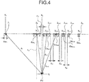
FIG. 4 is a diagram for explanation of a method of calculating timing for transmission of ultrasonic waves from each vibration element. -
FIG. 5 is a flow chart illustrating a flow of an ultrasonic flaw detection process according to an embodiment of the present invention. -
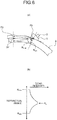
FIG. 6 is a diagram for explanation of a method of calculating a center angle of sector scanning. -
FIG. 7 is a schematic diagram illustrating a configuration of an ultrasonic flaw detection device according to the embodiment of the present invention. -
FIG. 8 is a plan view illustrating a configuration of the matrix array probe illustrated inFIG. 7 . -
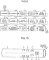
FIG. 9 is a diagram illustrating a flow of a general UOE steel pipe manufacturing process. -
FIG. 10 is a schematic diagram illustrating arrangement positions of plural matrix array probes included in a manipulator. -
FIG. 11 is a schematic diagram illustrating a configuration of matrix array probes for flaw detection on a thickness center portion. -
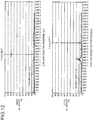
FIG. 12 is a diagram illustrating an example of results of ultrasonic flaw detection. -
FIG. 13 is a diagram illustrating an example of S/N ratios and refraction angles for welded steel pipes having different values of t/D. -
FIG. 14 is a diagram illustrating an example of a relation between refraction angle of ultrasonic waves and echo height. -
FIG. 15 is a diagram for explanation of a relation between refraction angles of ultrasonic waves and apparent sensor sizes. - According to the present invention, in an ultrasonic flaw detection method where the vertical incidence method is used, ultrasonic waves are focused in a pipe axis direction for realization of a high S/N ratio by compensation of reduction in the defect detection sensitivity at a high refraction angle. Specifically, the defect detection sensitivity when the refraction angle of ultrasonic waves is 80° is 12 dB lower than the defect detection sensitivity when the refraction angle of ultrasonic waves is 70°. Therefore, when the refraction angle of ultrasonic waves is 80°, the defect detection sensitivity is increased by at least 12 dB or more through focusing of the ultrasonic waves in the pipe axis direction.
- Effects of the increase in the defect detection sensitivity obtained by the focusing of the ultrasonic waves in the pipe axis direction are able to be evaluated by use of Equation (1) below. Specifically, from Equation (1), a sound pressure near a focus upon focusing of sound waves is able to be calculated. In Equation (1), P represents sound pressure near a focal position of ultrasonic waves, P0 represents transmission sound pressure, x represents position of a sound axis field, fop represents focal distance, D represents size of a sensor that transmits the ultrasonic waves, λ represents wavelength of the ultrasonic waves, and J represents a focusing coefficient. The focusing coefficient J is defined by Equation (2). However, if x = fop in Equation (1), sound pressure is calculated as P/P0 = πJ.


-
FIG. 1 illustrates results of calculation of a relation between pipe axis direction widths (opening widths) of sensors that transmit ultrasonic waves and sound pressure of the ultrasonic waves at focal positions, where the sound velocity in the wedge is 2340 m/sec, the sound velocity of shear waves in the steel is 3230 m/sec, and the height of the wedge is 25 mm. Specifically,FIG. 1 illustrates the sound pressure at a focal position P3 inFIG. 4 described later.FIG. 1 illustrates change in sound pressure over focal positions for each opening width, with the sound pressure by an ultrasonic probe having a vibrator size (an opening width) of 8 mm without focusing being a reference (that is, 0 dB). As illustrated inFIG. 1 , the greater the opening width of the sensor becomes, the stronger the sound pressure obtained at the focal position is. Specifically,FIG. 1 illustrates that for obtainment of a strong sound pressure equal to or larger than 12 dB at a focal position reached after transmission through steel when the focal position is in a range of 40 mm to 160 mm, an opening width of about 30 mm is needed. On another front, for sufficient sector scanning, vibration elements (also called vibrators) of at least 8ch or more are desirably used. Therefore, when a matrix array probe of 128ch is used as a sensor, preferably: vibration elements forming the sensor are in an array of 16ch × 8ch; there are 16ch in the pipe axis direction because a large opening width like 30 mm is needed for obtainment of a sufficient defect detection sensitivity increasing effect in the pipe axis direction, in which the ultrasonic waves are focused; and there are 8ch in a pipe circumference direction, in which sector scanning is performed. - On the other hand, in a phased array type ultrasonic flaw detection method, grating lobes that are unnecessary signal peaks are generated, and become a cause of noise. Therefore, gratings lobes are desirably generated as little as possible. Equation (3) below is generally known as a condition for an array pitch (a vibration element pitch) Ep of vibration elements for no generation of grating lobes. In Equation (3), λ represents wavelength of ultrasonic waves, and θ represents polarization angle. The phased array type is a method where, by transmission and reception of ultrasonic waves delayed in phase from vibration elements arranged in an array, (i) a transmission direction and a reception direction of the ultrasonic waves are able to be controlled, (ii) the ultrasonic waves are able to be focused, and (iii) electronic scanning is possible without mechanical scanning of positions of the vibration elements.

- When the sound velocity in the wedge is 2340 m/sec, the frequency of ultrasonic waves is 5 MHz, which is generally used in welded steel pipe flaw detection, and the polarization angle with respect to the pipe axis direction is 0°; according to Equation (3) above, the vibration element pitch Ep for no generation of grating lobes is found to be about 0.46 mm. That is, when the vibration element pitch Ep is equal to or less than 0.46 mm, grating lobes will not be generated.
- However, even if the vibration elements of 16ch are arranged in the pipe axis direction at a vibration element pitch Ep of 0.46 mm, the opening width of the matrix array probe in the pipe axis direction will only be 7.36 mm (= 0.46 mm × 16ch). As described already, the opening width of the matrix array probe in the pipe axis direction needs to be of a large opening of 35 mm or the like for compensation of reduction in the defect detection sensitivity at a high refraction angle by focusing of ultrasonic waves, and thus the opening width of 7.36 mm is not sufficient.
- Therefore, arrangement positions of the vibration elements in the pipe axis direction when the vibration element pitch Ep is larger than the wavelength λ of ultrasonic waves will be discussed. For N vibration elements to form a preset opening width W, the vibration element pitch Ep must be W/N. A vibration element width Ew is of course less than the vibration element pitch Ep. If the vibration element pitch Ep is larger than the wavelength λ of ultrasonic waves, the vibration element width Ew is preferably made as large as possible in relation to the vibration element pitch Ep. Grating lobes are thereby reduced. Specifically, to make grating lobes equal to or less than -12 dB in relation to the main lobe, the vibration element pitch Ep and the vibration element width Ew are designed such that Ew/Ep ≥ 0.84, and to make grating lobes equal to or less than -18 dB, the vibration element pitch Ep and the vibration element width Ew are designed such that Ew/Ep ≥ 0.94.
- If the vibration element width Ew is increased, however, the directivity angle of the vibration element is narrowed, and the directivity angles of the vibration elements will overlap one another farther from the plane where the vibration elements are arranged. In this case, at a side close to the arrangement positions of the vibration elements, the directivity angles of the vibration elements do not overlap one another, and it will thus be difficult for ultrasound waves to be focused sufficiently. On the contrary, if the vibration element width Ew of a vibration element is decreased, the directivity angle of the vibration element is widened, and thus the directivity angles of the vibration elements overlap one another at a side closer to the plane where the vibration elements are arranged. Thereby, as compared with the case where the vibration element width Ew is wide, ultrasonic waves are able to be focused nearer, but it becomes easier for grating lobes to be generated.
- Thus, according to the present invention, ultrasonic flaw detection is performed by use of a matrix array probe having vibration elements arranged as illustrated in
FIG. 2 . In the matrix array probe illustrated inFIG. 2 ,vibration elements FIG. 2 , the center coordinate of the n-th (where n = 1 to m) vibration element is Xn, the vibration element width thereof is Ewn, and the vibration element pitch is Ep. A directivity angle φn of thevibration element 2n arranged at the n-th position is able to be calculated by Equation (4) below.
- When a distance from the center position (X = Xc) to the nearest focal position P1 in flaw detection is a focal distance fmin: for ultrasonic waves transmitted from the vibration elements to overlap one another sufficiently from the focal distance fmin, and a wide focal position range to be realized; a vibration element width Ewn and a center coordinate Xn satisfying Equation (5) below may be calculated, and each vibration element may be placed at the calculated position.

- In Equation (5), an angle θn is an angle formed between a normal line Ln passing through the center coordinate Xn of the n-
th vibration element 2n and a line segment Ln' joining the center coordinate Xn of the n-th vibration element 2n and the focal position P1, and is able to be calculated by Equation (6) below. If the directivity angle φn of the n-th vibration element 2n is larger than this angle θn, ultrasonic waves will sufficiently overlap one another from the focal position P1. Generation of grating lobes and reduction in the defect detection sensitivity at a high refraction angle are thereby able to be reduced. In Equation (6), Xc represents the center position of the matrix array probe. Moreover, the value of the vibration element pitch Ep is desirably made as small as possible.
- A set position for a
matrix array probe 2 in ultrasonic flaw detection illustrated inFIG. 3 is able to be calculated from Equations (7) and (8) below by use of a thickness t and an outer diameter R of a welded steel pipe S. In Equation (8), PWD represents, as illustrated inFIG. 3 , a distance on the circumference of the welded steel pipe S, from an incident position P2 of ultrasonic waves to a focal position (the butted position of the groove) P3 where a defect is present. Further, a distance TF, over which the ultrasound waves are propagated through the steel is able to be calculated by Equation (9) below. Furthermore, when the height of awedge 3 is H, the sound velocity in thewedge 3 is Vw, and the sound velocity of shear waves in the steel is Vs; a focal distance fp of the ultrasonic waves is able to be calculated by Equation (10) below. InFIG. 3 , θi represents the incidence angle of the ultrasonic waves, θr represents the refraction angle of the ultrasonic waves, and ○ represents the center position of the welded steel pipe S.


- Next, a method of calculating timing for transmission of ultrasonic waves from vibration elements for focusing of the ultrasonic waves on the focal position P3 will be described by use of
FIG. 4 . As illustrated inFIG. 4 , for focusing of ultrasonic waves on the focal position P3, firstly, a propagation time of ultrasonic waves from an arrangement position of each vibration element to the focal position P3 is calculated. Specifically, as expressed by Equation (11) below, through division of a distance dn from the arrangement position of the n-th vibration element to the focal position P3 by the sound velocity Vw in the wedge, a propagation time Tn from the arrangement position of the n-th vibration element to the focal position P3 is able to be found.
- As in
FIG. 4 , if m vibration elements have been arranged in the pipe axis direction, by the above described calculation for each of the first to the m-th vibration elements, the propagation time Tn is found. Subsequently, as expressed by Equation (12) below, the maximum value (the maximum propagation time) Tmax of the propagation time Tn found for each vibration element is calculated. As expressed by Equation (13) below, by subtraction of the maximum propagation time Tmax from each propagation time Tn, an absolute time of a result of the subtraction is found as a timing (a delay time Tdn) for transmission of ultrasonic waves by each vibration element. Ultrasonic waves are thereby able to be focused on the focal position P3.

- Focusing ultrasonic waves in a radial cross section direction (a C-direction) of the welded steel pipe orthogonal to the pipe axis direction may be considered also, but as illustrated in
FIG. 15(a) to FIG. 15(c) , a sensor (an ultrasonic probe) that transmits ultrasonic waves decreases in its apparent size in association with increase in the refraction angle. Further, as expressed by Equation (2), the focusing coefficient J is proportional to a squared value of the size of the sensor that transmits the ultrasonic waves. Therefore, in this case, for obtainment of sufficient sound pressure, the size of the sensor that transmits the ultrasonic waves needs to be increased, and thus this focusing is not realistic. Specifically, if the frequency is 5 MHz, the size of a sensor for transmission needs to be, for example, equal to or larger than 50 mm. If a sensor having such a large opening width in the C-direction is attempted to be applied, the minimum allowable proximity will be increased and the propagation distance of ultrasonic waves will be increased, and as a result, the sound pressure increasing effect by the focusing will not be obtained sufficiently. Therefore, this focusing is not very realistic. Therefore, according to the present invention, ultrasonic waves are focused in a pipe axis direction, rather than along a radial cross section direction of a welded steel pipe orthogonal to the pipe axis direction. - According to the present invention, an ultrasonic flaw detection process is desirably executed after sensitivity calibration of a matrix array probe is performed by adjustment of an incidence angle condition and a focusing condition of ultrasonic waves through use of a test piece for calibration having an population planar defect formed at a butted portion of a groove. Specifically, an ultrasonic flaw detection process is performed according to a flow illustrated in
FIG. 5 . As illustrated inFIG. 5 , in the ultrasonic flaw detection process, firstly, initial conditions for ultrasonic flaw detection are calculated (Step S1). Specifically, the set position (the incident position) P2 for vertical incidence of ultrasonic waves on the center position Xc of a welding root surface, and a delay time of each vibration element for flaw direction with the ultrasonic waves being focused in the pipe axis direction and the incidence angle of the ultrasonic waves being swinged in the C-direction, are calculated. In this calculation, the focal position P3 of the ultrasonic waves is able to be calculated from the position of the artificial planar defect, the incidence position of the ultrasonic waves, and the set position of the matrix array probe. Subsequently, the matrix array probe and wedge (probe) are set on an outer peripheral surface of the welded steel pipe such that ultrasonic waves are able to be incident on the incident position P2 calculated in the processing of Step S1 (Step S2). - Subsequently, ultrasonic waves that have been focused in the pipe axis direction with the calculated delay times of the vibration elements are transmitted and received while the incidence angle is swinged in the C-direction (Step S3). Specifically, as illustrated in
FIG. 6(a) and FIG. 6(b) , scanning (sector scanning) with ultrasonic waves is performed at an angle pitch Rd of, for example, 1°, over an angle range from a refraction angle Rmin to a refraction angle Rmax, the echo intensity from the defect at each angle is recorded, and a refraction angle, at which the echo intensity is the highest, is detected as a center angle Rc of flaw detection. InFIG. 6(a) and FIG. 6(b) , DF represents the artificial planar defect. Subsequently, various set values for ultrasonic flaw detection are calculated (Step S4), and the sensitivity of each vibration element is calibrated according to the various set values calculated, such that the intensity of an output signal of the vibration element is within a predetermined range (Step S5). Thereafter, ultrasonic flaw detection is performed by scanning at refraction angles at a predetermined angle pitch of, for example, 2°, in a predetermined angle range of, for example, ±4°, around the center angle Rc determined in the processing of Step S3 (Step S6). The angle range and the angle pitch of the sector scanning are determined by an operator, according to variables, such as the pipe diameter and thickness of the welded steel pipe, the acoustical anisotropy of the welded steel pipe, and the frequency of ultrasonic waves used. - By ultrasonic flaw detection through scanning at refraction angles at a predetermined angle pitch in a predetermined angle range around the center angle Rc as described above, ultrasonic waves are able to be made incident on the welding root surface even if the incidence angle of the ultrasonic waves is somewhat changed due to wobbling of the mechanical parts that drive the vibration elements and variation in the acoustical anisotropy of the welded steel pipe, and thus influence of the change in the incidence angle of the ultrasonic waves on the defect detection sensitivity is able to be reduced. Further, since the refraction angle, at which the echo intensity is the highest, is set as the center angle Rc of flaw detection, variation in the defect detection sensitivity according to the personal error of the operator who adjusts the angle and set position of the probe is able to be reduced.
- Next, with reference to
FIG. 7 andFIG. 8 , a configuration of an ultrasonic flaw detection device according to the embodiment of the present invention will be described.FIG. 7 is a schematic diagram illustrating the configuration of the ultrasonic flaw detection device according to the embodiment of the present invention.FIG. 8 is a plan view illustrating a configuration of a matrix array probe illustrated inFIG. 7 . InFIG. 7 andFIG. 8 , an L-direction represents a pipe axis direction, the C-direction represents a direction orthogonal to the pipe axis direction on a horizontal plane, and a Z-direction represents a direction orthogonal to the L-direction and C-direction. - As illustrated in
FIG. 7 , an ultrasonicflaw detection device 1 according to the embodiment of the present invention includes, as main components thereof, thematrix array probe 2, thewedge 3, an ultrasonic wave transmitting and receivingunit 4, and anevaluation unit 5. - The
matrix array probe 2 is on an outer surface of the welded steel pipe S to be inspected, and transmits and receives ultrasonic waves UB to and from the welded steel pipe S via thewedge 3. As illustrated inFIG. 8 , according to this embodiment, thematrix array probe 2 is formed of vibration elements of 128ch arranged lattice-like, and vibration elements of 16ch are arranged in the L-direction and vibration elements of 8ch are arranged in the C-direction. Vibration element widths of these vibration elements are designed to gradually decrease outward from the center position along the L-direction, and the vibration element width Ew and the center coordinate Xn of each vibration element are designed to satisfy Equation (5) above. Thereby, according to this embodiment, the opening width of thematrix array probe 2 in the L-direction is about 34 mm, and the opening width in the C-direction is about 10 mm. - The
wedge 3 is formed as a polyhedron having an installation surface where thematrix array probe 2 is installed, and is formed of polystyrene. According to this embodiment, ultrasonic flaw detection is performed by: setting the sound velocity in thewedge 3 to 2340 m/sec; preparing a plurality of thewedges 3, by which the refraction angles of ultrasonic waves respectively become 60°, 65°, 70°, and 80°; and attaching thewedge 3 having the refraction angle that is closest to a theoretically calculated refraction angle θr from the incident position P2 of the ultrasonic waves UB. For example, when a thickness center portion of a welded portion of a welded steel pipe S having an outer diameter of 1067 mm and a thickness of 44.5 mm is subjected to flaw detection, a refraction angle θr of the ultrasonic waves UB from the incident position P2 is calculated to be 73.4° when the sound velocity of shear waves in the steel is 3230 m/sec. In this case, ultrasonic flaw detection is thus performed by attachment of thewedge 3, by which the refraction angle θr of the ultrasonic waves UB becomes 75°, to thematrix array probe 2. According to this embodiment, a thickness center portion of a welded portion is subjected to flaw detection, but a flaw detection range according to the present invention is not limited to a thickness center portion of a welded portion, and any planar defect in a range irradiated with ultrasonic waves may be subjected to flaw detection. - The ultrasonic wave transmitting and receiving
unit 4 controls the ultrasonic flaw detection process for a welded portion of the welded steel pipe S according to the ultrasonic flaw detection process illustrated inFIG. 5 by outputting transmission and reception commands for ultrasonic wave signals to the vibration elements included in thematrix array probe 2. Specifically, the ultrasonic wave transmitting and receivingunit 4 is formed of an information processing device, such as a microcomputer, and executes the ultrasonic flaw detection process for a welded portion of the welded steel pipe S by executing a computer program prescribing the ultrasonic flaw detection process illustrated inFIG. 5 . The ultrasonic wave transmitting and receivingunit 4 outputs ultrasonic wave signals reflected from the welded seam portion and received by thematrix array probe 2, to theevaluation unit 5. InFIG. 7 , WB represents welding bead, CL represents the center position of the welded portion with respect to a circumferential direction of the welded steel pipe S, and P3 represents the focal position. - After performing predetermined processing on the ultrasonic wave signals output from the ultrasonic wave transmitting and receiving
unit 4, theevaluation unit 5 executes, based on the ultrasonic wave signals that have been subjected to the predetermined processing, quality evaluation of the welded portion of the welded steel pipe, such as determination of whether or not any defect is present in the welded portion. Specifically, theevaluation unit 5 determines whether or not the intensity of the ultrasonic wave signals is equal to or larger than a predetermined threshold, and if the intensity of the ultrasonic wave signals is equal to or larger than the predetermined threshold, theevaluation unit 5 determines that a defect is present in the welded portion. Theevaluation unit 5 provides information related to a result of the quality evaluation for the welded portion of the welded steel pipe, to an operator, by outputting and recording the result of the quality evaluation for the welded portion of the welded steel pipe. A position where the defect has been detected is marked for the welded steel pipe having the defect detected in the welded portion. The welded steel pipe that has been marked is sent to an inspection process that is manually performed, and an operator performs ultrasonic flaw detection around the marked portion again and performs final judgement of acceptance for the quality of the welded portion. The ultrasonicflaw detection device 1 according to the embodiment of the present invention is also used in this manual inspection by the inspector. - In an example, quality of a welded portion of a UOE steel pipe was evaluated by use of the ultrasonic
flaw detection device 1 according to the embodiment of the present invention. Specifically, the ultrasonicflaw detection device 1 according to the embodiment of the present invention was applied to a general manufacturing process for UOE steel pipes illustrated inFIG. 9 . In the manufacturing process for UOE steel pipes illustrated inFIG. 9 , firstly, after U-ing press forming and O-ing press forming on a thick steel plate are performed (Steps S11 and S12), an inner side and an outer side of butted portions of the thick steel plate are weld-bonded (Steps S13 and S14), and ultrasonic testing (UT) and radiographic testing (RT) on the welded portion are executed (Steps S15 and S16). Subsequently, after a pipe expansion process is performed on the welded steel pipe (Step S17), a hydrostatic test is performed thereon (Step S18), and ultrasonic testing (UT) and radiographic testing (RT) are executed again on the welded portion (Steps S19 and S20). Lastly, after an end face finishing process, an exterior dimension inspection process, pipe end radiographic testing, a basis weight measurement process, and an inner and outer surface coating process are performed on the welded steel pipe (Steps S21 to S25), the welded steel pipe is shipped. In this example, the ultrasonicflaw detection device 1 according to the embodiment of the present invention was applied to the ultrasonic testing at Step S15 and Step S19. - Further, in this example, a manipulator including plural matrix array probes 2A to 2H as illustrated in
FIG. 10 was installed in the ultrasonic flaw detection device. These matrix array probes are respectively assigned with roles, such that the matrix array probes 2A and 2B are for flaw detection on a thickness center portion, the matrix array probes 2C and 2D are for flaw detection on an outer surface, the matrix array probes 2E and 2F are for flaw detection on an inner surface, and the matrix array probes 2G and 2H are for flaw detection on a bead portion. The manipulator puts each matrix array probe on the welded steel pipe S, and ultrasonic testing on the welded portion is performed while the welded steel pipe S is transferred in a longitudinal direction (a transfer direction). In this example, among the matrix array probes 2A to 2H, the embodiment illustrated inFIG. 7 was applied to the matrix array probes 2A and 2B for flaw detection on a thickness center portion, and the angle beam phased array UT technique was applied to the other matrix array probes. - Details of a configuration of the matrix array probes 2A and 2B for flaw detection on a thickness center portion will now be described by use of
FIG. 11(a) and FIG. 11(b) . As also illustrated inFIG. 10 , the plural matrix array probes 2A to 2H are arranged to perform flaw detection, for each part to be subjected to ultrasonic flaw detection from both sides, with the welding bead WB interposed therebetween. The matrix array probes 2A and 2B for flaw detection on a thickness center portion are similarly arranged, as illustrated inFIG. 11(a) andFIG. 11(b) , to perform flaw detection from both sides, with the welding bead WB interposed therebetween. Further, as illustrated inFIG. 11(b) , the matrix array probes 2A and 2B forming a pair are arranged to be displaced from each other by about 5 mm along the pipe axis direction. When the vertical incidence method is applied, transmissively propagated waves of ultrasonic waves transmitted from the matrix array probes 2A and 2B forming a pair become noise and the detectability is thereby reduced. Therefore, the matrix array probes 2A and 2B forming a pair were arranged to be displaced from each other in the pipe axis direction. - Further, in this example, ultrasonic waves were transmitted and received as focused beams. Furthermore, the matrix phased array probes 2A and 2B each having an opening width of about 34 mm in the pipe axis direction and an opening width of 5 mm to 18 mm in the pipe circumference direction were used, and their beam widths were made to be equal to or less than 1 mm at minimum. Therefore, it is difficult for ultrasonic waves to be adapted to the position of the artificial flaw at the time of adjustment of sensitivity. Thus, a mechanism, which enables the matrix array probes including the matrix array probes 2A and 2B for flaw detection on a thickness center portion to be precisely scanned individually in the pipe axis direction, was provided. Specifically, as illustrated in
FIG. 11(a) , each matrix array probe was connected to amanipulator 7 via ascanning mechanism 6, and the matrix array probe was made movable by thescanning mechanism 6 in an L-direction LA or LB and a C-direction CA or CB. The opening width in the pipe circumference direction is changed according to: a sector scanning condition, such as a condition enabling a range of 1/3 of the thickness to be irradiated with ultrasonic waves; and the beam diameter. - An example of results of actual ultrasonic flaw detection are illustrated in
FIG. 12(a) and FIG. 12(b) . Flaw detection (sector scanning) was performed with three ultrasonic beams that were at a 3° pitch with respect to a center refraction angle.FIG. 12(a) and FIG. 12(b) respectively illustrate results (vertical axis: echo height, horizontal axis: pipe axis direction position) of flaw detection on a 12.7-mm welded steel pipe having an outer diameter of 56 inches and an artificial flaw (a flat bottomed hole) of φ3.0 mm preformed in its welded portion, by use of thematrix array probe 2A and thematrix array probe 2B. As illustrated inFIG. 12(a) and FIG. 12(b) , an F-echo was clearly observed with both of the matrix array probes 2A and 2B, and the artificial flaw of φ3.0 mm was able to be detected adequately. Further,FIG. 13(a) and FIG. 13(b) illustrate S/N ratios and refraction angles in flaw detection on artificial flaws (flat bottomed holes) of φ3.0 mm formed in thickness center portions of welded steel pipes having different values of t/D. As illustrated inFIG. 13(a) and FIG. 13(b) , even when the refraction angle was as large as about 82°, a satisfactory S/N ratio equal to or larger than 24 dB was obtained. An S/N ratio generally required for an artificial flaw (a flat bottomed hole) of φ3.0 mm is equal to or larger than 12 dB. - The embodiment, to which the invention made by the inventors has been applied, has been described above, but the present invention is not limited to the description and drawings forming a part of disclosure of the present invention through this embodiment. Any other embodiments, examples, operation techniques, and the like implemented by those skilled in the art or the like based on the embodiment are thus all included in the scope of the present invention.
- According to the present invention, an ultrasonic flaw detection device and an ultrasonic flaw detection method, which enable reduction of influence of change in incidence angle of ultrasonic waves on defect detection sensitivity and variation in the defect detection sensitivity due to manual adjustment by an operator, are able to be provided. Further, according to the present invention, a method of manufacturing a welded steel pipe and a welded steel pipe quality control method, which enable manufacture of a welded steel pipe having a welded portion that is high in quality, by reduction of influence of change in incidence angle of ultrasonic waves on defect detection sensitivity and variation in the defect detection sensitivity due to manual adjustment by an operator, are able to be provided.
-
- 1
- ULTRASONIC FLAW DETECTION DEVICE
- 2
- MATRIX ARRAY PROBE
- 3
- WEDGE
- 4
- ULTRASONIC WAVE TRANSMITTING AND RECEIVING UNIT
- 5
- EVALUATION UNIT
- S
- WELDED STEEL PIPE
Claims (7)
- An ultrasonic flaw detection device that detects a planar defect present at a butted portion of a groove in a welded portion of a welded steel pipe, the ultrasonic flaw detection device comprising:a matrix array probe that is arranged, via a wedge, at a position on an outer peripheral surface of the welded steel pipe, the position enabling ultrasonic waves to be vertically incident on a welding root surface, the matrix array probe configured to transmit ultrasonic waves focused in a pipe axis direction to the welding root surface, and to receive ultrasonic waves reflected at the welding root surface;an ultrasonic wave transmitting and receiving unit that controls the matrix array probe such that the matrix array probe receives the reflected ultrasonic waves reflected at the welding root surface; andan evaluation unit that detects the planar defect based on the reflected ultrasonic waves received by the ultrasonic wave transmitting and receiving unit, whereinthe matrix array probe has plurality of vibration elements arranged lattice-like,an array pitch of the vibration elements in the pipe axis direction is larger than a wavelength of ultrasonic waves transmitted and received,widths of the vibration elements in the pipe axis direction decrease outward in the pipe axis direction from a pipe axis direction center position of the matrix array probe, andthe widths and center coordinates of the vibration elements in the pipe axis direction have been adjusted such that all of ultrasonic waves from the vibration elements overlap in a focal position control range for the ultrasonic waves.
- The ultrasonic flaw detection device according to claim 1, wherein the ultrasonic wave transmitting and receiving unit transmits ultrasonic waves to the welding root surface while changing, at a predetermined angle pitch, a refraction angle of the ultrasonic waves in a predetermined angle range around a predetermined center angle.
- An ultrasonic flaw detection method, comprising the step of:
detecting a planar defect present at a butted portion of a groove in a welded portion of a welded steel pipe by using the ultrasonic flaw detection device according to claim 1 or 2. - The ultrasonic flaw detection method according to claim 3, comprising the steps of:transmitting ultrasonic waves to an artificial planar defect formed at a center position of the welding root surface while changing, at an arbitrary angle pitch, a refraction angle of the ultrasonic waves in an arbitrary angle range;receiving reflected waves of the ultrasonic waves reflected at the artificial planar defect; andfinding a refraction angle, at which the reflected waves of the ultrasonic waves are the highest in intensity, as the center angle.
- The ultrasonic flaw detection method according to claim 3 or 4, comprising the steps of:preparing beforehand plurality of wedges that differ in the refraction angles; andin detecting the planar defect, selecting a wedge having a refraction angle that is closest to a desired refraction angle, and using the selected wedge in combination with the matrix array probe.
- A method of manufacturing a welded steel pipe, comprising the steps of:detecting any planar defect present at a butted portion of a groove in a welded portion of a welded steel pipe by using the ultrasonic flaw detection device according to claim 1 or 2; andmanufacturing the welded steel pipe based on a result of the detection.
- A welded steel pipe quality control method, comprising the steps of:detecting any planar defect present at a butted portion of a groove in a welded portion of a welded steel pipe by using the ultrasonic flaw detection device according to claim 1 or 2; andevaluating quality of the welded steel pipe based on a result of the detection.
Applications Claiming Priority (2)
| Application Number | Priority Date | Filing Date | Title |
|---|---|---|---|
| JP2016142197 | 2016-07-20 | ||
| PCT/JP2017/024280 WO2018016303A1 (en) | 2016-07-20 | 2017-07-03 | Ultrasonic flaw detection device, ultrasonic flaw detection method, method of manufacturing welded steel pipe, and welded steel pipe quality control method |
Publications (3)
| Publication Number | Publication Date |
|---|---|
| EP3489676A1 true EP3489676A1 (en) | 2019-05-29 |
| EP3489676A4 EP3489676A4 (en) | 2019-07-17 |
| EP3489676B1 EP3489676B1 (en) | 2024-09-04 |
Family
ID=60992994
Family Applications (1)
| Application Number | Title | Priority Date | Filing Date |
|---|---|---|---|
| EP17830823.5A Active EP3489676B1 (en) | 2016-07-20 | 2017-07-03 | Ultrasonic flaw detection device, ultrasonic flaw detection method, method of manufacturing welded steel pipe, and welded steel pipe quality control method |
Country Status (7)
| Country | Link |
|---|---|
| US (1) | US10908126B2 (en) |
| EP (1) | EP3489676B1 (en) |
| JP (1) | JP6274378B1 (en) |
| KR (1) | KR102291701B1 (en) |
| CN (1) | CN109564197B (en) |
| RU (1) | RU2704429C1 (en) |
| WO (1) | WO2018016303A1 (en) |
Families Citing this family (13)
| Publication number | Priority date | Publication date | Assignee | Title |
|---|---|---|---|---|
| WO2019117120A1 (en) * | 2017-12-12 | 2019-06-20 | 日本製鉄株式会社 | Defect detection device, and defect detection method and program |
| US11474076B2 (en) | 2019-02-28 | 2022-10-18 | Olympus NDT Canada Inc. | Acoustic model acoustic region of influence generation |
| CN110208388A (en) * | 2019-04-26 | 2019-09-06 | 中国大唐集团科学技术研究院有限公司火力发电技术研究院 | A kind of method that tube interior axial flaw quickly detects |
| US11982641B2 (en) * | 2019-05-30 | 2024-05-14 | Shimadzu Corporation | Method and device for examining clinched portion of tubular body |
| JP6972082B2 (en) | 2019-10-30 | 2021-11-24 | 株式会社東芝 | Processing systems, processing equipment, processing methods, programs, and storage media |
| CN110763765A (en) * | 2019-11-29 | 2020-02-07 | 中国石油天然气集团公司管材研究所 | A multi-channel non-contact automatic ultrasonic testing system and method for seamless steel pipes |
| US11408860B2 (en) * | 2020-03-30 | 2022-08-09 | Olympus NDT Canada Inc. | Ultrasound probe with row-column addressed array |
| CN112379001B (en) * | 2020-11-17 | 2024-03-29 | 洛阳轴承集团股份有限公司 | Technological method for reducing detection blind area by ultrasonic flaw detection of railway bearing ring |
| KR102561059B1 (en) | 2021-03-15 | 2023-07-28 | 김효섭 | Ultrasonics Wave Inspection Apparatus for Weld Zone of Steel Pipe Having Angle Adjustable Wheel Unit |
| CN113899816B (en) * | 2021-09-10 | 2022-06-17 | 国营芜湖机械厂 | Ultrasonic nondestructive testing device and method for T-shaped composite structure and R-region testing method and device |
| JP2024055188A (en) * | 2022-10-06 | 2024-04-18 | Jfeスチール株式会社 | Ultrasonic inspection method |
| US12174148B1 (en) | 2023-06-26 | 2024-12-24 | Universky Material Technology Co., Ltd. | Method for determining the quality of diffusion welding by means of non-destructive testing |
| CN116482229B (en) * | 2023-06-26 | 2023-09-08 | 河北宇天材料科技有限公司 | Nondestructive testing judging method for welding quality of diffusion welding |
Family Cites Families (25)
| Publication number | Priority date | Publication date | Assignee | Title |
|---|---|---|---|---|
| SU150689A1 (en) | 1961-04-26 | 1961-11-30 | Е.Б. Виксман | Control method of the weld |
| JPS61270055A (en) | 1985-05-25 | 1986-11-29 | Kironii Sangyo Kk | Automatic tracing detector |
| SU1280530A1 (en) | 1985-08-13 | 1986-12-30 | Белоярская атомная электростанция им.И.В.Курчатова | Device for automatic ultrasonic checking of welds |
| JPH022932A (en) * | 1988-06-16 | 1990-01-08 | Mitsubishi Electric Corp | Array type probe |
| US4890268A (en) | 1988-12-27 | 1989-12-26 | General Electric Company | Two-dimensional phased array of ultrasonic transducers |
| EP0685068B1 (en) | 1993-02-18 | 1997-04-16 | KRAUTKRÄMER GmbH & Co. | Ultrasonic testing device for weld seams in pipes, sheets and containers |
| JPH08166813A (en) * | 1994-12-14 | 1996-06-25 | Fanuc Ltd | Tracking control method for robot accompanied by weaving operation |
| JPH11183446A (en) * | 1997-12-25 | 1999-07-09 | Nkk Corp | Ultrasonic flaw detection method and apparatus for welds |
| JP3446009B2 (en) * | 1998-09-25 | 2003-09-16 | Jfeスチール株式会社 | Ultrasonic flaw detection method and apparatus for steel pipe |
| US7263888B2 (en) * | 2003-10-16 | 2007-09-04 | General Electric Company | Two dimensional phased arrays for volumetric ultrasonic inspection and methods of use |
| CN101017154B (en) | 2006-02-07 | 2011-03-23 | 哈尔滨工业大学 | Ultrasonic phased array inspection instrument |
| CA2593893C (en) * | 2007-01-26 | 2016-11-08 | Roentgen Technische Dienst B.V. | Improved technique and phased array transducer for ultrasonic inspection of coarse grained, anisotropic welds |
| JP4910770B2 (en) | 2007-02-28 | 2012-04-04 | Jfeスチール株式会社 | Tubular ultrasonic inspection apparatus and ultrasonic inspection method |
| JP4910768B2 (en) | 2007-02-28 | 2012-04-04 | Jfeスチール株式会社 | Calibration method of ultrasonic flaw detection, tube quality control method and manufacturing method |
| JP5258218B2 (en) | 2007-07-10 | 2013-08-07 | 新日鐵住金株式会社 | Inspection method for weld defects in ERW pipe |
| JP5076984B2 (en) * | 2008-03-13 | 2012-11-21 | Jfeスチール株式会社 | Ultrasonic flaw detection method, ultrasonic flaw detection apparatus and manufacturing method for electric sewing tube |
| DE102010063438A1 (en) | 2010-12-17 | 2012-06-21 | Robert Bosch Gmbh | Sound wave based sensor for environment detection and use of the same |
| JP5588918B2 (en) * | 2011-04-21 | 2014-09-10 | 日立Geニュークリア・エナジー株式会社 | Ultrasonic inspection method |
| CN202372480U (en) | 2011-12-13 | 2012-08-08 | 衡阳华菱钢管有限公司 | Small-caliber steel pipe longitudinal inner wall flaw detection sample pipe |
| CN102747726B (en) | 2012-07-02 | 2016-05-18 | 江苏楚鼎建设工程有限公司 | The dry pore-forming steel pipe post of ultra-deep foundation pit pile driving construction engineering method |
| MX340378B (en) | 2012-07-04 | 2016-07-07 | Nippon Steel & Sumitomo Metal Corp | Defect detection device, defect detection method, program, and storage medium. |
| JP6197458B2 (en) * | 2013-08-05 | 2017-09-20 | 新日鐵住金株式会社 | Defect inspection apparatus, defect inspection method, program, and storage medium |
| JP2015040697A (en) * | 2013-08-20 | 2015-03-02 | 三菱日立パワーシステムズ株式会社 | Ultrasonic flaw detection sensor and ultrasonic flaw detection method |
| CN104227182B (en) * | 2014-09-01 | 2016-06-08 | 湖北源盛钢构有限公司 | The moulding process of the main weld seam of joist steel unclear completepenetration I level component |
| CN104475941A (en) | 2014-12-03 | 2015-04-01 | 宝鸡石油钢管有限责任公司 | Multiple-wire submerged arc welding process suitable for thick-wall straight-seam steel pipes X70 |
-
2017
- 2017-07-03 RU RU2019104693A patent/RU2704429C1/en active
- 2017-07-03 US US16/318,601 patent/US10908126B2/en active Active
- 2017-07-03 EP EP17830823.5A patent/EP3489676B1/en active Active
- 2017-07-03 JP JP2017557225A patent/JP6274378B1/en active Active
- 2017-07-03 CN CN201780044361.8A patent/CN109564197B/en active Active
- 2017-07-03 KR KR1020197000566A patent/KR102291701B1/en active Active
- 2017-07-03 WO PCT/JP2017/024280 patent/WO2018016303A1/en not_active Ceased
Also Published As
| Publication number | Publication date |
|---|---|
| WO2018016303A1 (en) | 2018-01-25 |
| US20190242854A1 (en) | 2019-08-08 |
| EP3489676B1 (en) | 2024-09-04 |
| KR102291701B1 (en) | 2021-08-19 |
| US10908126B2 (en) | 2021-02-02 |
| RU2704429C1 (en) | 2019-10-30 |
| JPWO2018016303A1 (en) | 2018-07-19 |
| JP6274378B1 (en) | 2018-02-07 |
| CN109564197B (en) | 2022-03-08 |
| EP3489676A4 (en) | 2019-07-17 |
| CN109564197A (en) | 2019-04-02 |
| KR20190016086A (en) | 2019-02-15 |
Similar Documents
| Publication | Publication Date | Title |
|---|---|---|
| EP3489676B1 (en) | Ultrasonic flaw detection device, ultrasonic flaw detection method, method of manufacturing welded steel pipe, and welded steel pipe quality control method | |
| JP4910768B2 (en) | Calibration method of ultrasonic flaw detection, tube quality control method and manufacturing method | |
| JP4910770B2 (en) | Tubular ultrasonic inspection apparatus and ultrasonic inspection method | |
| EP2124046B1 (en) | Method for controlling quality of tubular body and tubular body manufacturing method | |
| Liu et al. | Guided waves based diagnostic imaging of circumferential cracks in small-diameter pipe | |
| CN103969341B (en) | The extraordinary probe of Austenitic stainless steel pipe butt girth welding seam ultrasound examination | |
| US20070000328A1 (en) | Ultrasonic method for the accurate measurement of crack height in dissimilar metal welds using phased array | |
| KR20100045284A (en) | Calibration block (reference block) and calibration procedure for phased-array ultrasonic inspection | |
| KR101163554B1 (en) | Calibration block for phased-array ultrasonic inspection and verification | |
| WO2020250378A1 (en) | Ultrasound flaw detection method, ultrasound flaw detection device, manufacturing equipment line for steel material, manufacturing method for steel material, and quality assurance method for steel material | |
| JP2010517034A (en) | Improved technique and phased array transducer for ultrasonic inspection of coarse grain anisotropic welds | |
| KR20100124238A (en) | Calibration (Contrast) Specimen and Calibration Procedure for Phased Array Ultrasonic Testing | |
| EP3100041B1 (en) | Device and method for the non-destructive testing of a test object by means of ultrasound in accordance with the reference body method | |
| CN203758968U (en) | Ultrasonic-detecting special probe for butt-joint ring welding seam of austenite stainless steel tube | |
| Ginzel | CIVA as an aid to understanding ultrasonic anisotropy in steel | |
| CA3108661C (en) | Ultrasonic testing using a phased array | |
| JPS6126857A (en) | Ultrasonic flaw detecting method and defect deciding method of centrifugally cast iron pipe | |
| US11578971B2 (en) | Ultrasonic testing using a phased array | |
| AU2021200957B2 (en) | Ultrasonic testing using a phased array | |
| KR101163552B1 (en) | Sensistivity calibration referece block of stainless steel/duplex steel for phased-array ultrasonic inspection | |
| GINZEL et al. | Acoustic Velocity Determination for AUT on Spiral Pipe Girth Welds |
Legal Events
| Date | Code | Title | Description |
|---|---|---|---|
| STAA | Information on the status of an ep patent application or granted ep patent |
Free format text: STATUS: THE INTERNATIONAL PUBLICATION HAS BEEN MADE |
|
| PUAI | Public reference made under article 153(3) epc to a published international application that has entered the european phase |
Free format text: ORIGINAL CODE: 0009012 |
|
| STAA | Information on the status of an ep patent application or granted ep patent |
Free format text: STATUS: REQUEST FOR EXAMINATION WAS MADE |
|
| 17P | Request for examination filed |
Effective date: 20190219 |
|
| AK | Designated contracting states |
Kind code of ref document: A1 Designated state(s): AL AT BE BG CH CY CZ DE DK EE ES FI FR GB GR HR HU IE IS IT LI LT LU LV MC MK MT NL NO PL PT RO RS SE SI SK SM TR |
|
| AX | Request for extension of the european patent |
Extension state: BA ME |
|
| A4 | Supplementary search report drawn up and despatched |
Effective date: 20190614 |
|
| RIC1 | Information provided on ipc code assigned before grant |
Ipc: G01N 29/26 20060101AFI20190607BHEP Ipc: G01N 29/04 20060101ALI20190607BHEP Ipc: G01N 29/22 20060101ALI20190607BHEP |
|
| DAV | Request for validation of the european patent (deleted) | ||
| DAX | Request for extension of the european patent (deleted) | ||
| STAA | Information on the status of an ep patent application or granted ep patent |
Free format text: STATUS: EXAMINATION IS IN PROGRESS |
|
| 17Q | First examination report despatched |
Effective date: 20201208 |
|
| GRAP | Despatch of communication of intention to grant a patent |
Free format text: ORIGINAL CODE: EPIDOSNIGR1 |
|
| STAA | Information on the status of an ep patent application or granted ep patent |
Free format text: STATUS: GRANT OF PATENT IS INTENDED |
|
| INTG | Intention to grant announced |
Effective date: 20240423 |
|
| GRAS | Grant fee paid |
Free format text: ORIGINAL CODE: EPIDOSNIGR3 |
|
| GRAA | (expected) grant |
Free format text: ORIGINAL CODE: 0009210 |
|
| STAA | Information on the status of an ep patent application or granted ep patent |
Free format text: STATUS: THE PATENT HAS BEEN GRANTED |
|
| AK | Designated contracting states |
Kind code of ref document: B1 Designated state(s): AL AT BE BG CH CY CZ DE DK EE ES FI FR GB GR HR HU IE IS IT LI LT LU LV MC MK MT NL NO PL PT RO RS SE SI SK SM TR |
|
| REG | Reference to a national code |
Ref country code: GB Ref legal event code: FG4D |
|
| REG | Reference to a national code |
Ref country code: CH Ref legal event code: EP |
|
| REG | Reference to a national code |
Ref country code: IE Ref legal event code: FG4D |
|
| REG | Reference to a national code |
Ref country code: DE Ref legal event code: R096 Ref document number: 602017084689 Country of ref document: DE |
|
| REG | Reference to a national code |
Ref country code: LT Ref legal event code: MG9D |
|
| REG | Reference to a national code |
Ref country code: NL Ref legal event code: MP Effective date: 20240904 |
|
| PG25 | Lapsed in a contracting state [announced via postgrant information from national office to epo] |
Ref country code: NO Free format text: LAPSE BECAUSE OF FAILURE TO SUBMIT A TRANSLATION OF THE DESCRIPTION OR TO PAY THE FEE WITHIN THE PRESCRIBED TIME-LIMIT Effective date: 20241204 |
|
| PG25 | Lapsed in a contracting state [announced via postgrant information from national office to epo] |
Ref country code: GR Free format text: LAPSE BECAUSE OF FAILURE TO SUBMIT A TRANSLATION OF THE DESCRIPTION OR TO PAY THE FEE WITHIN THE PRESCRIBED TIME-LIMIT Effective date: 20241205 Ref country code: FI Free format text: LAPSE BECAUSE OF FAILURE TO SUBMIT A TRANSLATION OF THE DESCRIPTION OR TO PAY THE FEE WITHIN THE PRESCRIBED TIME-LIMIT Effective date: 20240904 Ref country code: PL Free format text: LAPSE BECAUSE OF FAILURE TO SUBMIT A TRANSLATION OF THE DESCRIPTION OR TO PAY THE FEE WITHIN THE PRESCRIBED TIME-LIMIT Effective date: 20240904 |
|
| PG25 | Lapsed in a contracting state [announced via postgrant information from national office to epo] |
Ref country code: BG Free format text: LAPSE BECAUSE OF FAILURE TO SUBMIT A TRANSLATION OF THE DESCRIPTION OR TO PAY THE FEE WITHIN THE PRESCRIBED TIME-LIMIT Effective date: 20240904 |
|
| PG25 | Lapsed in a contracting state [announced via postgrant information from national office to epo] |
Ref country code: LV Free format text: LAPSE BECAUSE OF FAILURE TO SUBMIT A TRANSLATION OF THE DESCRIPTION OR TO PAY THE FEE WITHIN THE PRESCRIBED TIME-LIMIT Effective date: 20240904 |
|
| PG25 | Lapsed in a contracting state [announced via postgrant information from national office to epo] |
Ref country code: HR Free format text: LAPSE BECAUSE OF FAILURE TO SUBMIT A TRANSLATION OF THE DESCRIPTION OR TO PAY THE FEE WITHIN THE PRESCRIBED TIME-LIMIT Effective date: 20240904 |
|
| PG25 | Lapsed in a contracting state [announced via postgrant information from national office to epo] |
Ref country code: ES Free format text: LAPSE BECAUSE OF FAILURE TO SUBMIT A TRANSLATION OF THE DESCRIPTION OR TO PAY THE FEE WITHIN THE PRESCRIBED TIME-LIMIT Effective date: 20240904 Ref country code: RS Free format text: LAPSE BECAUSE OF FAILURE TO SUBMIT A TRANSLATION OF THE DESCRIPTION OR TO PAY THE FEE WITHIN THE PRESCRIBED TIME-LIMIT Effective date: 20241204 |
|
| PG25 | Lapsed in a contracting state [announced via postgrant information from national office to epo] |
Ref country code: RS Free format text: LAPSE BECAUSE OF FAILURE TO SUBMIT A TRANSLATION OF THE DESCRIPTION OR TO PAY THE FEE WITHIN THE PRESCRIBED TIME-LIMIT Effective date: 20241204 Ref country code: PL Free format text: LAPSE BECAUSE OF FAILURE TO SUBMIT A TRANSLATION OF THE DESCRIPTION OR TO PAY THE FEE WITHIN THE PRESCRIBED TIME-LIMIT Effective date: 20240904 Ref country code: NO Free format text: LAPSE BECAUSE OF FAILURE TO SUBMIT A TRANSLATION OF THE DESCRIPTION OR TO PAY THE FEE WITHIN THE PRESCRIBED TIME-LIMIT Effective date: 20241204 Ref country code: LV Free format text: LAPSE BECAUSE OF FAILURE TO SUBMIT A TRANSLATION OF THE DESCRIPTION OR TO PAY THE FEE WITHIN THE PRESCRIBED TIME-LIMIT Effective date: 20240904 Ref country code: HR Free format text: LAPSE BECAUSE OF FAILURE TO SUBMIT A TRANSLATION OF THE DESCRIPTION OR TO PAY THE FEE WITHIN THE PRESCRIBED TIME-LIMIT Effective date: 20240904 Ref country code: GR Free format text: LAPSE BECAUSE OF FAILURE TO SUBMIT A TRANSLATION OF THE DESCRIPTION OR TO PAY THE FEE WITHIN THE PRESCRIBED TIME-LIMIT Effective date: 20241205 Ref country code: FI Free format text: LAPSE BECAUSE OF FAILURE TO SUBMIT A TRANSLATION OF THE DESCRIPTION OR TO PAY THE FEE WITHIN THE PRESCRIBED TIME-LIMIT Effective date: 20240904 Ref country code: ES Free format text: LAPSE BECAUSE OF FAILURE TO SUBMIT A TRANSLATION OF THE DESCRIPTION OR TO PAY THE FEE WITHIN THE PRESCRIBED TIME-LIMIT Effective date: 20240904 Ref country code: BG Free format text: LAPSE BECAUSE OF FAILURE TO SUBMIT A TRANSLATION OF THE DESCRIPTION OR TO PAY THE FEE WITHIN THE PRESCRIBED TIME-LIMIT Effective date: 20240904 |
|
| REG | Reference to a national code |
Ref country code: AT Ref legal event code: MK05 Ref document number: 1720867 Country of ref document: AT Kind code of ref document: T Effective date: 20240904 |
|
| PG25 | Lapsed in a contracting state [announced via postgrant information from national office to epo] |
Ref country code: NL Free format text: LAPSE BECAUSE OF FAILURE TO SUBMIT A TRANSLATION OF THE DESCRIPTION OR TO PAY THE FEE WITHIN THE PRESCRIBED TIME-LIMIT Effective date: 20240904 |
|
| PG25 | Lapsed in a contracting state [announced via postgrant information from national office to epo] |
Ref country code: IS Free format text: LAPSE BECAUSE OF FAILURE TO SUBMIT A TRANSLATION OF THE DESCRIPTION OR TO PAY THE FEE WITHIN THE PRESCRIBED TIME-LIMIT Effective date: 20250104 Ref country code: PT Free format text: LAPSE BECAUSE OF FAILURE TO SUBMIT A TRANSLATION OF THE DESCRIPTION OR TO PAY THE FEE WITHIN THE PRESCRIBED TIME-LIMIT Effective date: 20250106 |
|
| PG25 | Lapsed in a contracting state [announced via postgrant information from national office to epo] |
Ref country code: RO Free format text: LAPSE BECAUSE OF FAILURE TO SUBMIT A TRANSLATION OF THE DESCRIPTION OR TO PAY THE FEE WITHIN THE PRESCRIBED TIME-LIMIT Effective date: 20240904 Ref country code: SM Free format text: LAPSE BECAUSE OF FAILURE TO SUBMIT A TRANSLATION OF THE DESCRIPTION OR TO PAY THE FEE WITHIN THE PRESCRIBED TIME-LIMIT Effective date: 20240904 |
|
| PG25 | Lapsed in a contracting state [announced via postgrant information from national office to epo] |
Ref country code: EE Free format text: LAPSE BECAUSE OF FAILURE TO SUBMIT A TRANSLATION OF THE DESCRIPTION OR TO PAY THE FEE WITHIN THE PRESCRIBED TIME-LIMIT Effective date: 20240904 Ref country code: AT Free format text: LAPSE BECAUSE OF FAILURE TO SUBMIT A TRANSLATION OF THE DESCRIPTION OR TO PAY THE FEE WITHIN THE PRESCRIBED TIME-LIMIT Effective date: 20240904 |
|
| PG25 | Lapsed in a contracting state [announced via postgrant information from national office to epo] |
Ref country code: CZ Free format text: LAPSE BECAUSE OF FAILURE TO SUBMIT A TRANSLATION OF THE DESCRIPTION OR TO PAY THE FEE WITHIN THE PRESCRIBED TIME-LIMIT Effective date: 20240904 |
|
| PG25 | Lapsed in a contracting state [announced via postgrant information from national office to epo] |
Ref country code: IT Free format text: LAPSE BECAUSE OF FAILURE TO SUBMIT A TRANSLATION OF THE DESCRIPTION OR TO PAY THE FEE WITHIN THE PRESCRIBED TIME-LIMIT Effective date: 20240904 Ref country code: SK Free format text: LAPSE BECAUSE OF FAILURE TO SUBMIT A TRANSLATION OF THE DESCRIPTION OR TO PAY THE FEE WITHIN THE PRESCRIBED TIME-LIMIT Effective date: 20240904 |
|
| REG | Reference to a national code |
Ref country code: DE Ref legal event code: R097 Ref document number: 602017084689 Country of ref document: DE |
|
| PG25 | Lapsed in a contracting state [announced via postgrant information from national office to epo] |
Ref country code: DK Free format text: LAPSE BECAUSE OF FAILURE TO SUBMIT A TRANSLATION OF THE DESCRIPTION OR TO PAY THE FEE WITHIN THE PRESCRIBED TIME-LIMIT Effective date: 20240904 |
|
| PGFP | Annual fee paid to national office [announced via postgrant information from national office to epo] |
Ref country code: GB Payment date: 20250529 Year of fee payment: 9 |
|
| PLBE | No opposition filed within time limit |
Free format text: ORIGINAL CODE: 0009261 |
|
| STAA | Information on the status of an ep patent application or granted ep patent |
Free format text: STATUS: NO OPPOSITION FILED WITHIN TIME LIMIT |
|
| 26N | No opposition filed |
Effective date: 20250605 |
|
| PG25 | Lapsed in a contracting state [announced via postgrant information from national office to epo] |
Ref country code: SE Free format text: LAPSE BECAUSE OF FAILURE TO SUBMIT A TRANSLATION OF THE DESCRIPTION OR TO PAY THE FEE WITHIN THE PRESCRIBED TIME-LIMIT Effective date: 20240904 |
|
| PGFP | Annual fee paid to national office [announced via postgrant information from national office to epo] |
Ref country code: DE Payment date: 20250528 Year of fee payment: 9 |
|
| REG | Reference to a national code |
Ref country code: CH Ref legal event code: H13 Free format text: ST27 STATUS EVENT CODE: U-0-0-H10-H13 (AS PROVIDED BY THE NATIONAL OFFICE) Effective date: 20260224 |
|
| PG25 | Lapsed in a contracting state [announced via postgrant information from national office to epo] |
Ref country code: LU Free format text: LAPSE BECAUSE OF NON-PAYMENT OF DUE FEES Effective date: 20250703 |
|
| REG | Reference to a national code |
Ref country code: BE Ref legal event code: MM Effective date: 20250731 |
|
| PG25 | Lapsed in a contracting state [announced via postgrant information from national office to epo] |
Ref country code: BE Free format text: LAPSE BECAUSE OF NON-PAYMENT OF DUE FEES Effective date: 20250731 |
|
| PG25 | Lapsed in a contracting state [announced via postgrant information from national office to epo] |
Ref country code: FR Free format text: LAPSE BECAUSE OF NON-PAYMENT OF DUE FEES Effective date: 20250731 |
|
| PG25 | Lapsed in a contracting state [announced via postgrant information from national office to epo] |
Ref country code: CH Free format text: LAPSE BECAUSE OF NON-PAYMENT OF DUE FEES Effective date: 20250731 |