EP3489516A1 - Vakuumpumpe - Google Patents
Vakuumpumpe Download PDFInfo
- Publication number
- EP3489516A1 EP3489516A1 EP17203509.9A EP17203509A EP3489516A1 EP 3489516 A1 EP3489516 A1 EP 3489516A1 EP 17203509 A EP17203509 A EP 17203509A EP 3489516 A1 EP3489516 A1 EP 3489516A1
- Authority
- EP
- European Patent Office
- Prior art keywords
- vacuum pump
- pumping
- switching
- pump according
- working
- Prior art date
- Legal status (The legal status is an assumption and is not a legal conclusion. Google has not performed a legal analysis and makes no representation as to the accuracy of the status listed.)
- Granted
Links
Images


Classifications
-
- F—MECHANICAL ENGINEERING; LIGHTING; HEATING; WEAPONS; BLASTING
- F04—POSITIVE - DISPLACEMENT MACHINES FOR LIQUIDS; PUMPS FOR LIQUIDS OR ELASTIC FLUIDS
- F04C—ROTARY-PISTON, OR OSCILLATING-PISTON, POSITIVE-DISPLACEMENT MACHINES FOR LIQUIDS; ROTARY-PISTON, OR OSCILLATING-PISTON, POSITIVE-DISPLACEMENT PUMPS
- F04C23/00—Combinations of two or more pumps, each being of rotary-piston or oscillating-piston type, specially adapted for elastic fluids; Pumping installations specially adapted for elastic fluids; Multi-stage pumps specially adapted for elastic fluids
- F04C23/001—Combinations of two or more pumps, each being of rotary-piston or oscillating-piston type, specially adapted for elastic fluids; Pumping installations specially adapted for elastic fluids; Multi-stage pumps specially adapted for elastic fluids of similar working principle
-
- F—MECHANICAL ENGINEERING; LIGHTING; HEATING; WEAPONS; BLASTING
- F04—POSITIVE - DISPLACEMENT MACHINES FOR LIQUIDS; PUMPS FOR LIQUIDS OR ELASTIC FLUIDS
- F04B—POSITIVE-DISPLACEMENT MACHINES FOR LIQUIDS; PUMPS
- F04B37/00—Pumps having pertinent characteristics not provided for in, or of interest apart from, groups F04B25/00 - F04B35/00
- F04B37/10—Pumps having pertinent characteristics not provided for in, or of interest apart from, groups F04B25/00 - F04B35/00 for special use
- F04B37/14—Pumps having pertinent characteristics not provided for in, or of interest apart from, groups F04B25/00 - F04B35/00 for special use to obtain high vacuum
-
- F—MECHANICAL ENGINEERING; LIGHTING; HEATING; WEAPONS; BLASTING
- F04—POSITIVE - DISPLACEMENT MACHINES FOR LIQUIDS; PUMPS FOR LIQUIDS OR ELASTIC FLUIDS
- F04B—POSITIVE-DISPLACEMENT MACHINES FOR LIQUIDS; PUMPS
- F04B41/00—Pumping installations or systems specially adapted for elastic fluids
- F04B41/06—Combinations of two or more pumps
-
- F—MECHANICAL ENGINEERING; LIGHTING; HEATING; WEAPONS; BLASTING
- F04—POSITIVE - DISPLACEMENT MACHINES FOR LIQUIDS; PUMPS FOR LIQUIDS OR ELASTIC FLUIDS
- F04B—POSITIVE-DISPLACEMENT MACHINES FOR LIQUIDS; PUMPS
- F04B49/00—Control, e.g. of pump delivery, or pump pressure of, or safety measures for, machines, pumps, or pumping installations, not otherwise provided for, or of interest apart from, groups F04B1/00 - F04B47/00
- F04B49/06—Control using electricity
-
- F—MECHANICAL ENGINEERING; LIGHTING; HEATING; WEAPONS; BLASTING
- F04—POSITIVE - DISPLACEMENT MACHINES FOR LIQUIDS; PUMPS FOR LIQUIDS OR ELASTIC FLUIDS
- F04C—ROTARY-PISTON, OR OSCILLATING-PISTON, POSITIVE-DISPLACEMENT MACHINES FOR LIQUIDS; ROTARY-PISTON, OR OSCILLATING-PISTON, POSITIVE-DISPLACEMENT PUMPS
- F04C18/00—Rotary-piston pumps specially adapted for elastic fluids
- F04C18/30—Rotary-piston pumps specially adapted for elastic fluids having the characteristics covered by two or more of groups F04C18/02, F04C18/08, F04C18/22, F04C18/24, F04C18/48, or having the characteristics covered by one of these groups together with some other type of movement between co-operating members
- F04C18/34—Rotary-piston pumps specially adapted for elastic fluids having the characteristics covered by two or more of groups F04C18/02, F04C18/08, F04C18/22, F04C18/24, F04C18/48, or having the characteristics covered by one of these groups together with some other type of movement between co-operating members having the movement defined in group F04C18/08 or F04C18/22 and relative reciprocation between the co-operating members
- F04C18/344—Rotary-piston pumps specially adapted for elastic fluids having the characteristics covered by two or more of groups F04C18/02, F04C18/08, F04C18/22, F04C18/24, F04C18/48, or having the characteristics covered by one of these groups together with some other type of movement between co-operating members having the movement defined in group F04C18/08 or F04C18/22 and relative reciprocation between the co-operating members with vanes reciprocating with respect to the inner member
-
- F—MECHANICAL ENGINEERING; LIGHTING; HEATING; WEAPONS; BLASTING
- F04—POSITIVE - DISPLACEMENT MACHINES FOR LIQUIDS; PUMPS FOR LIQUIDS OR ELASTIC FLUIDS
- F04C—ROTARY-PISTON, OR OSCILLATING-PISTON, POSITIVE-DISPLACEMENT MACHINES FOR LIQUIDS; ROTARY-PISTON, OR OSCILLATING-PISTON, POSITIVE-DISPLACEMENT PUMPS
- F04C25/00—Adaptations of pumps for special use of pumps for elastic fluids
- F04C25/02—Adaptations of pumps for special use of pumps for elastic fluids for producing high vacuum
-
- F—MECHANICAL ENGINEERING; LIGHTING; HEATING; WEAPONS; BLASTING
- F04—POSITIVE - DISPLACEMENT MACHINES FOR LIQUIDS; PUMPS FOR LIQUIDS OR ELASTIC FLUIDS
- F04C—ROTARY-PISTON, OR OSCILLATING-PISTON, POSITIVE-DISPLACEMENT MACHINES FOR LIQUIDS; ROTARY-PISTON, OR OSCILLATING-PISTON, POSITIVE-DISPLACEMENT PUMPS
- F04C28/00—Control of, monitoring of, or safety arrangements for, pumps or pumping installations specially adapted for elastic fluids
- F04C28/02—Control of, monitoring of, or safety arrangements for, pumps or pumping installations specially adapted for elastic fluids specially adapted for several pumps connected in series or in parallel
-
- F—MECHANICAL ENGINEERING; LIGHTING; HEATING; WEAPONS; BLASTING
- F04—POSITIVE - DISPLACEMENT MACHINES FOR LIQUIDS; PUMPS FOR LIQUIDS OR ELASTIC FLUIDS
- F04C—ROTARY-PISTON, OR OSCILLATING-PISTON, POSITIVE-DISPLACEMENT MACHINES FOR LIQUIDS; ROTARY-PISTON, OR OSCILLATING-PISTON, POSITIVE-DISPLACEMENT PUMPS
- F04C28/00—Control of, monitoring of, or safety arrangements for, pumps or pumping installations specially adapted for elastic fluids
- F04C28/06—Control of, monitoring of, or safety arrangements for, pumps or pumping installations specially adapted for elastic fluids specially adapted for stopping, starting, idling or no-load operation
- F04C28/065—Capacity control using a multiplicity of units or pumping capacities, e.g. multiple chambers, individually switchable or controllable
-
- F—MECHANICAL ENGINEERING; LIGHTING; HEATING; WEAPONS; BLASTING
- F04—POSITIVE - DISPLACEMENT MACHINES FOR LIQUIDS; PUMPS FOR LIQUIDS OR ELASTIC FLUIDS
- F04C—ROTARY-PISTON, OR OSCILLATING-PISTON, POSITIVE-DISPLACEMENT MACHINES FOR LIQUIDS; ROTARY-PISTON, OR OSCILLATING-PISTON, POSITIVE-DISPLACEMENT PUMPS
- F04C2210/00—Fluid
- F04C2210/12—Fluid auxiliary
-
- F—MECHANICAL ENGINEERING; LIGHTING; HEATING; WEAPONS; BLASTING
- F04—POSITIVE - DISPLACEMENT MACHINES FOR LIQUIDS; PUMPS FOR LIQUIDS OR ELASTIC FLUIDS
- F04C—ROTARY-PISTON, OR OSCILLATING-PISTON, POSITIVE-DISPLACEMENT MACHINES FOR LIQUIDS; ROTARY-PISTON, OR OSCILLATING-PISTON, POSITIVE-DISPLACEMENT PUMPS
- F04C2240/00—Components
- F04C2240/70—Use of multiplicity of similar components; Modular construction
Definitions
- the present invention relates to a vacuum pump having a first working pumping section and at least one second working pumping section.
- a known vacuum pump of the type mentioned is designed such that the working pumping sections are connected in parallel. As a result, a relatively large pumping speed is achieved at the beginning of a pumping process.
- the parallel connection of the working pumping sections is disadvantageous with regard to the achievable end pressure, that is to say the minimum pressure attainable at the inlet of the vacuum pump.
- the described conflict of objectives should be resolved.
- the vacuum pump may be operated at the beginning of a pumpdown operation in parallel with the work pumping sections to realize a high pumping speed, and later, in particular when the pumping capacity in the in-line mode exceeds that of the parallel operation, switch to the in-line mode, so as to further effectively evacuate to ensure a particularly low final pressure.
- the vacuum pump according to the invention can be used flexibly for various applications.
- it can be waived by the manufacturer to offer mechanically different vacuum pumps on the one hand with parallel connection and on the other hand with series connection.
- the additional design effort for the control device can be kept low.
- the vacuum pump is a rotary displacement vacuum pump, in particular a rotary vane pump.
- both or all work pumping sections operate according to the rotary displacement or rotary valve principle.
- the work pumping sections are driven by a common shaft. This represents a structurally simple and thus cost-effective solution.
- control device is designed to carry out the switching upon reaching a predetermined and / or predefinable switching gas pressure. This is advantageous because the pumping speed is dependent on the prevailing at the time operating pressure and thus the pumping speed can be precisely selected.
- the switching gas pressure may e.g. be a prevailing at an inlet of the vacuum pump gas pressure. This makes it advantageous to use that the inlet pressure of a vacuum pump is usually monitored anyway, so that no additional pressure detection devices are needed.
- Advantageous values for the switching gas pressure are below 1 hPa and / or above 0.01 hPa, preferably above 0.10 hPa.
- control device is designed to carry out the switching as a function of known Saug hotelssverierin the vacuum pump in series connection and parallel connection depending on a prevailing at an inlet of the vacuum pump gas pressure.
- switchover between series and parallel connection can take place at or at an intersection of the pumping speed profiles.
- control device is designed to start a pumping operation with a parallel connection of the working pumping sections and to switch to a series connection of the working pumping sections as soon as the pumping speed of the vacuum pump in parallel is smaller or at least substantially equal to a pumping speed of the vacuum pump connected in series. In this way, in each case an advantageous pumping speed can be set.
- control device comprises at least one switching valve, in particular a solenoid valve.
- switching valve in particular a solenoid valve.
- Such changeover valves allow easy, reliable control or switching.
- a three-way valve in particular with an operating voltage of 24V, may be provided.
- the switching valve may e.g. at least two switch positions, of which one of the series circuit and the other of the parallel circuit is assigned.
- the switching valve has at least one third switching position, in which the working pumping sections are separated from an inlet of the vacuum pump.
- the work pumping sections and an outlet of the vacuum pump can be surely separated from the inlet.
- the function of an inlet or safety valve can be taken over by the switching valve.
- the vacuum pump thus has in particular no additional inlet or safety valve. This not only saves costs, but it can also be a disadvantage often encountered in intake valves avoid, namely that in differential pressure inlet valves low differential pressures often lead to insufficient closure of the inlet.
- the reversing valve can effectively close the inlet at any differential pressures.
- a high level of operational reliability can be achieved, for example, if the changeover valve is de-energized in the third switching position or if the changeover valve is designed such that it automatically assumes and holds the third switching position when de-energized. In this way, in the event of a power failure, a backflow of the process gas into the recipient and in particular a resulting reverse rotation of the pump shaft is prevented.
- the switching valve may e.g. be designed as a 5/3-way valve. This allows a structurally simple design.
- a drive for at least one of, in particular both or all, work pumping sections comprises a DC motor, which is electrically connected in series with the switching valve. This can be in einfaeher Way the motor can be controlled synchronously to the switching valve. In particular, in this case, the de-energized state for switching the switching valve in a safety position or the third switching position lead.
- control device comprises at least one further valve, which separates the first work pumping section from an outlet of the vacuum pump for realizing the series connection.
- the object of the invention is also achieved by a method according to claim 15, and in particular by the fact that during a pumping operation between a series connection and a parallel connection of the working pumping sections is switched.
- the vacuum pump according to the invention can be further developed in the sense of the embodiments of the method described herein.
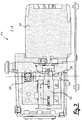
- Fig. 1 is shown as a rotary vane vacuum pump and hereinafter referred to as a vacuum pump 10 Rotationsverdrängervakuumpumpe of the prior art.
- the vacuum pump 10 sucks in a working fluid at an inlet 28 and delivers it to an outlet 30, which is open to atmosphere, for example.
- Fig. 2 shows a sectional view of the vacuum pump 10 along the section line AA according to Fig. 1 , The cut runs parallel along a rotation axis of a rotor 12 of the vacuum pump 10.
- the vacuum pump 10 includes a safety valve 20, which prevents backflow of working fluid in case of failure of the pump.
- the safety valve 20 is pilot-controlled by a pressure pilot control.
- the vacuum pump 10 also includes a motor 26 for driving the rotor 12 of the vacuum pump 10. Between the motor 26 and the rotor 12, a clutch 27 is provided, which may be designed in particular as a magnetic coupling.
- a first work pumping section is defined by a slide 14 and a delivery chamber 15.
- a second work pumping section is defined by a slide 16 and a delivery chamber 17.
- the rotor has a slide 18, which rotates in a delivery chamber 19 to a To promote control fluid for the pressure precontrol.
- the illustrated vacuum pump 10 thus operates in the first working pumping section, in the second working pumping section and in the control pumping section in each case according to the rotary vane pumping principle.
- a respective pump section and a plurality of slides 14 and 18 may be provided.
- the rotor 12 is received and supported with its control section 18, 19 in a receiving part 24 and rotatably supported therein.
- the receiving part 24 forms with an outer surface 32 of a cylindrical basic shape, which is aligned concentrically with the axis of rotation of the rotor 12.
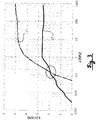
- the abscissa represents an inlet pressure of a vacuum pump according to the invention in logarithmic scale graduation.
- the ordinate shows the pumping speed of the pump in a simple graduation.
- the diagram shows two Saug banksverstructure depending on the inlet pressure, namely, a first pumping speed SP, which represents the Saug banksverlauf in a parallel circuit of the Häspumpabête, and a second Saug banksverlauf SR, which represents the Saug enquiriesverlauf at a series connection of the Häpumpabête.
- Fig. 3 illustrates impressively that the pumping speed at a high inlet pressure, ie in particular at the beginning of an Abpumpvorgangs starting from the atmospheric pressure in parallel operation is significantly greater than in series operation. However, only a significantly higher final pressure is achieved in parallel operation.
- the pumping speed curves intersect - in the example shown here - approximately at an inlet pressure of 0.15 hPA.
- the point of intersection and the courses per se are dependent on the structural design of the respective work pumping sections as well as on their size ratio to one another. In this case, the smaller the differences in size of the work pumping sections, the greater the increases in the pumping speed.
- intersection can be used advantageously as a switching point for the control device of the vacuum pump for switching between parallel and series operation.
- a switching gas pressure corresponding to the intersection point is determined and based on the control.
- FIG. 3 For a description of a pumpdown process, the diagram of Fig. 3 to read from right to left.
- An advantageous Abpumpvorgang in particular starting from the atmospheric pressure, runs in such a way that is started in parallel operation and there the high pumping speed is used according to SP for rapid evacuation.
- the system switches over to series operation, so that the higher pumping speed according to SR can then be utilized in the low pressure range and a lower discharge pressure can be achieved.
- a switching valve 40 is shown, which is designed as a 5/3-way valve and controls a vacuum pump according to the invention.
- the switching valve 40 has three switch positions (a), (b) and (c), in which two work pumping sections 42 and 44 are connected in different ways.
- the switching valve 40 is designed to select the desired switching position as a solenoid valve, with a corresponding magnet arrangement, however, is not shown in detail.
- switching position (a) all connections of the changeover valve 40 are separated from each other. Consequently, fluid can not flow from the inlet 28 to the outlet 30 and vice versa in this position.
- This switching position corresponds in particular to the third switching position described above. It can be taken in particular in the de-energized state of the switching valve 40.
- switching position (c) the working pumping sections 42 and 44, however, are connected in series.
- the switching valve 46 is closed, which is indicated by a transverse line.
- This switching position is preferably selected at low inlet pressures in order to achieve a particularly low final pressure can.
- the changeover valve 40 thus realizes the switching between series and parallel operation to increase performance on the one hand and at the same time a function as a safety valve on the other. Despite the structurally simple construction, therefore, the diverse advantages described herein can be achieved. If the invention for further development of the vacuum pump 10 according to Fig. 1 and 2 should be used, in particular by the safety function of the switching valve, the safety valve 20 and the control pump section 18, 19 for the pressure precontrol of the safety valve 20 can be saved.
Landscapes
- Engineering & Computer Science (AREA)
- Mechanical Engineering (AREA)
- General Engineering & Computer Science (AREA)
- Applications Or Details Of Rotary Compressors (AREA)
- Non-Positive Displacement Air Blowers (AREA)
Abstract
Description
- Die vorliegende Erfindung betrifft eine Vakuumpumpe mit einem ersten Arbeitspumpabschnitt und wenigstens einem zweiten Arbeitspumpabschnitt.
- Der Stand der Technik wird nachfolgend anhand des Beispiels von Drehschiebervakuumpumen mit zwei Arbeitspumpabschnitten beschrieben.
- Eine bekannte Vakuumpumpe der genannten Art ist derart ausgebildet, dass die Arbeitspumpabschnitte parallel geschaltet sind. Hierdurch wird ein relativ großes Saugvermögen am Anfang eines Abpumpvorganges verwirklicht. Die Parallelschaltung der Arbeitspumpabschnitte ist jedoch hinsichtlich des erreichbaren Enddrucks, also des minimal am Einlass der Vakuumpumpe erreichbaren Drucks, nachteilig.
- Für Anwendungen, bei denen ein besonders niedriger Enddruck benötigt wird, ist es im Stand der Technik bekannt, zwei Arbeitspumpabschnitte in Reihe zu schalten. Hierdurch kann - bei ansonsten baugleichen Arbeitspumpabschnitten - ein deutlich niedrigerer Enddruck erreicht werden. Allerdings ist hierbei das Saugvermögen bei hohen Einlassdrücken, also insbesondere am Anfang eines Abpumpvorgangs, im Vergleich zum Parallelbetrieb stark reduziert.
- Parallel arbeitende Vakuumpumpen der eingangs genannten Art eignen sich also für Anwendungen, bei denen ein schnelles Abpumpen Vorrang vor einem niedrigen erreichbaren Enddruck hat. Umgekehrt eignen sich in Reihe arbeitende Vakuumpumpen besonders für Anwendungen, bei denen ein schnelles Abpumpen weniger wichtig ist, dafür aber ein besonders niedriger Enddruck erreichbar sein soll.
- Erreichbarer Enddruck und Saugvermögen bei hohen Einlassdrücken stehen insofern also in einem Zielkonflikt.
- Es ist eine Aufgabe der Erfindung, die Leistung einer Vakuumpumpe der eingangs genannten Art zu verbessern, insbesondere sowohl ein hohes Saugvermögen bei hohen Drücken, insbesondere am Anfang eines Abpumpvorgangs, als auch einen niedrigen erreichbaren Enddruck zu verwirklichen. Es soll also insbesondere der beschriebene Zielkonflikt aufgelöst werden.
- Diese Aufgabe wird durch eine Vakuumpumpe mit den Merkmalen des Anspruchs 1 gelöst, und insbesondere dadurch, dass eine Steuereinrichtung vorgesehen ist, mit der zwischen einer Reihenschaltung und einer Parallelschaltung der Arbeitspumpabschnitte umgeschaltet werden kann.
- Hierdurch kann je nach Betriebszustand der Vakuumpumpe diejenige Betriebsart, also Reihen- bzw. Parallelschaltung, ausgewählt werden, welche eine in diesem Betriebszustand bessere Leistung erbringt. Die Vakuumpumpe kann also zum Beispiel am Anfang eines Abpumpvorgangs in Parallelschaltung der Arbeitspumpabschnitte betrieben werden, um ein hohes Saugvermögen zu realisieren, und später, insbesondere sobald das Saugvermögen im Reihenbetrieb dasjenige des Parallelbetriebs übersteigt, auf den Reihenbetrieb umschalten, um so eine weitere effektive Evakuierung bis hin zu einem besonders niedrigen Enddruck zu gewährleisten.
- Die erfindungsgemäße Vakuumpumpe ist für verschiedene Anwendungsfälle flexibel einsetzbar. Außerdem kann herstellerseitig darauf verzichtet werden, mechanisch unterschiedliche Vakuumpumpen einerseits mit Parallelschaltung und andererseits mit Reihenschaltung anzubieten. Hierdurch lassen sich die Teilevielfalt drastisch reduzieren und somit Kosten sparen. Der konstruktive Mehraufwand für die Steuereinrichtung kann dagegen gering gehalten werden. Ferner ergibt sich ein Kostenvorteil daraus, dass nun kleinere Pumpen durch Parallelschaltung in Anwendungen eingesetzt werden können, in denen bisher größere Pumpen zum Einsatz kamen.
- Soweit hierin auf hohe oder niedrige Drücke Bezug genommen wird, beziehen diese sich auf die konkrete Vakuumanwendung und sind nicht absolut zu verstehen. Für den einfachen Fall, dass im Ausgangszustand der Pumpe sowohl am Einlass als auch am Auslass atmosphärischer Druck herrscht, bezieht sich hoher Druck insbesondere auf Werte nahe dem atmosphärischen Druck.
- Die folgende Beschreibung bezieht sich beispielhaft vornehmlich auf Vakuumpumpen mit genau zwei Arbeitspumpabschnitten, die nach demselben Pumpprinzip arbeiten. Die genannten Beispiele lassen sich aber auch auf Pumpen mit drei oder mehr Arbeitspumpabschnitten und insbesondere auch auf Pumpen mit verschiedenartigen Arbeitspumpabschnitten übertragen.
- Gemäß einer Ausführungsform ist die Vakuumpumpe eine Rotationsverdrängervakuumpumpe, insbesondere eine Drehschieberpumpe. Insbesondere arbeiten beide oder alle Arbeitspumpabschnitte nach dem Rotationsverdränger- bzw. Drehschieberprinzip. Zum Beispiel sind die Arbeitspumpabschnitte durch eine gemeinsame Welle angetrieben. Dies stellt eine konstruktiv einfache und somit kostengünstige Lösung dar.
- Gemäß einer weiteren Ausführungsform ist die Steuereinrichtung dazu ausgebildet, die Umschaltung bei Erreichen eines vorgegebenen und/oder vorgebbaren Umschaltgasdrucks vorzunehmen. Dies ist deshalb vorteilhaft, da das Saugvermögen vom zum jeweiligen Zeitpunkt herrschenden Betriebsdruck abhängig ist und somit das Saugvermögen präzise gewählt werden kann.
- Der Umschaltgasdruck kann z.B. ein an einem Einlass der Vakuumpumpe herrschender Gasdruck sein. Hierdurch lässt sich vorteilhaft nutzen, dass der Einlassdruck einer Vakuumpumpe meist ohnehin überwacht wird, sodass keine zusätzlichen Druckermittlungseinrichtungen nötig sind.
- Vorteilhafte Werte für den Umschaltgasdruck liegen unterhalb von 1 hPa und/oder oberhalb von 0,01 hPa, bevorzugt oberhalb von 0,10 hPa.
- Bei einer Weiterbildung ist die Steuereinrichtung dazu ausgebildet, die Umschaltung in Abhängigkeit von bekannten Saugvermögensverläufen der Vakuumpumpe bei Reihenschaltung und bei Parallelschaltung jeweils in Abhängigkeit von einem an einem Einlass der Vakuumpumpe herrschenden Gasdruck vorzunehmen. Insbesondere kann die Umschaltung zwischen Reihen- und Parallelschaltung an oder bei einem Schnittpunkt der Saugvermögensverläufe erfolgen.
- Bei noch einer Weiterbildung ist die Steuereinrichtung dazu ausgebildet, einen Pumpvorgang mit einer Parallelschaltung der Arbeitspumpabschnitte zu beginnen und auf eine Reihenschaltung der Arbeitspumpabschnitte umzuschalten, sobald das Saugvermögen der Vakuumpumpe in Parallelschaltung kleiner oder zumindest im Wesentlichen gleich einem Saugvermögen der Vakuumpumpe in Reihenschaltung ist. Hierdurch kann jeweils ein vorteilhaftes Saugvermögen eingestellt werden.
- Bei einer weiteren Ausführungsform umfasst die Steuereinrichtung wenigstens ein Umschaltventil, insbesondere ein Magnetventil. Solche Umschaltventile erlauben eine einfache, zuverlässige Steuerung bzw. Umschaltung. Zum Beispiel kann ein Dreiwegeventil, insbesondere mit einer Betriebsspannung von 24V, vorgesehen sein.
- Das Umschaltventil kann z.B. wenigstens zwei Schaltstellungen aufweisen, von denen die eine der Reihenschaltung und die andere der Parallelschaltung zugeordnet ist.
- Bei einer weiteren Ausführungsform weist das Umschaltventil wenigstens eine dritte Schaltstellung auf, in der die Arbeitspumpabschnitte von einem Einlass der Vakuumpumpe getrennt sind. Hierdurch können die Arbeitspumpabschnitte und ein Auslass der Vakuumpumpe sicher von dem Einlass getrennt werden. Somit kann insbesondere die Funktion eines Einlass- bzw. Sicherheitsventils von dem Umschaltventil mit übernommen werden. Die Vakuumpumpe weist also insbesondere kein zusätzliches Einlass- oder Sicherheitsventil auf. Hierdurch lassen sich nicht nur Kosten sparen, sondern es lässt sich auch ein bei Einlassventilen häufig anzutreffender Nachteil vermeiden, nämlich dass bei Differenzdruck-Einlassventilen niedrige Differenzdrücke häufig zu einem unzureichenden Verschluss des Einlasses führen. Das Umschaltventil kann hingegen bei beliebigen Differenzdrücken den Einlass wirksam verschließen.
- Eine hohe Betriebssicherheit lässt sich beispielsweise erreichen, wenn das Umschaltventil in der dritten Schaltstellung stromlos ist bzw. wenn das Umschaltventil derart ausgebildet ist, dass es im stromlosen Zustand selbsttätig die dritte Schaltstellung einnimmt und hält. Hierdurch wird im Falle eines Stromausfalls ein Rückströmen des Prozessgases in den Rezipienten und insbesondere eine daraus resultierende umgekehrte Drehung der Pumpenwelle verhindert.
- Das Umschaltventil kann z.B. als 5/3-Wegeventil ausgebildet sein. Dies erlaubt eine konstruktiv einfache Gestaltung.
- Bei einer weiteren Ausführungsform umfasst ein Antrieb für zumindest einen der, insbesondere beide oder alle, Arbeitspumpabschnitte einen Gleichstrommotor, der mit dem Umschaltventil elektrisch in Reihe geschaltet ist. Hierdurch kann in einfaeher Weise der Motor synchron zum Umschaltventil gesteuert werden. Insbesondere kann hierbei der stromlose Zustand zum Schalten des Umschaltventils in eine Sicherheitsstellung bzw. die dritte Schaltstellung führen.
- Bei einem weiteren Ausführungsbeispiel umfasst die Steuereinrichtung wenigstens ein weiteres Ventil, welches zur Realisierung der Reihenschaltung den ersten Arbeitspumpabschnitt von einem Auslass der Vakuumpumpe trennt.
- Die Aufgabe der Erfindung wird auch durch ein Verfahren gemäß Anspruch 15 gelöst, und insbesondere dadurch, dass während eines Pumpvorgangs zwischen einer Reihenschaltung und einer Parallelschaltung der Arbeitspumpabschnitte umgeschaltet wird.
- Das erfindungsgemäße Verfahren lässt sich z.B. im Sinne der hierin beschriebenen Ausführungsformen der Vakuumpumpe weiterbilden und umgekehrt lässt sich die erfindungsgemäße Vakuumpumpe im Sinne der hierin beschriebenen Ausführungsformen des Verfahrens weiterbilden.
- Weitere Ausführungsformen der Erfindung sind den abhängigen Ansprüchen, der Beschreibung und den Figuren zu entnehmen.
- Die Erfindung wird nachfolgend lediglich beispielhaft anhand der schematischen Zeichnung erläutert.
- Fig. 1
- zeigt eine Rotationsverdrängervakuumpumpe des Standes der Technik in einer Seitenansicht.
- Fig. 2
- zeigt die Vakuumpumpe der
Fig. 1 in einer Schnittansicht entlang der Linie A-A vonFig. 1 . - Fig. 3
- zeigt für eine erfindungsgemäße Vakuumpumpe eine Auftragung des Saugvermögens in Abhängigkeit von einem Einlassdruck jeweils für eine Reihen- und eine Parallelschaltung der Arbeitspumpabschnitte.
- Fig. 4
- zeigt ein Schaltbild eines 5/3-Wegeventils zur Umschaltung zwischen Reihen- und Parallelbetrieb zweier Arbeitspumpabschnitte.
- In
Fig. 1 ist eine als Drehschiebervakuumpumpe ausgeführte und nachstehend als Vakuumpumpe 10 bezeichnete Rotationsverdrängervakuumpumpe des Standes der Technik dargestellt. Die Vakuumpumpe 10 saugt ein Arbeitsmedium an einem Einlass 28 an und fördert dieses zu einem Auslass 30, der zum Beispiel gegen Atmosphäre offen ist. -
Fig. 2 zeigt eine Schnittansicht der Vakuumpumpe 10 entlang der Schnittlinie A-A gemäßFig. 1 . Der Schnitt verläuft dabei parallel entlang einer Drehachse eines Rotors 12 der Vakuumpumpe 10. Die Vakuumpumpe 10 umfasst ein Sicherheitsventil 20, welches ein Rückfließen von Arbeitsmedium bei Ausfall der Pumpe verhindert. Das Sicherheitsventil 20 ist durch eine Druckvorsteuerung vorgesteuert. - Die Vakuumpumpe 10 umfasst außerdem einen Motor 26 zum Antrieb des Rotors 12 der Vakuumpumpe 10. Zwischen Motor 26 und Rotor 12 ist eine Kupplung 27 vorgesehen, welche insbesondere als Magnetkupplung ausgeführt sein kann.
- An dem Rotor 12 sind zwei Arbeitspumpabschnitte und ein Steuerpumpabschnitt ausgebildet. Ein erster Arbeitspumpabschnitt wird durch einen Schieber 14 und einen Förderraum 15 definiert. Ein zweiter Arbeitspumpabschnitt wird durch einen Schieber 16 und einen Förderraum 17 definiert. In dem Steuerpumpabschnitt weist der Rotor einen Schieber 18 auf, der in einem Förderraum 19 rotiert, um ein Steuerfluid für die Druckvorsteuerung zu fördern. Die gezeigte Vakuumpumpe 10 arbeitet also im ersten Arbeitspumpabschnitt, im zweiten Arbeitspumpabschnitt und im Steuerpumpabschnitt jeweils nach dem Drehschieberpumpprinzip. In einem jeweiligen Pumpabschnitt können auch mehrere Schieber 14 bzw. 18 vorgesehen sein.
- Der Rotor 12 ist mit seinem Steuerabschnitt 18, 19 in einem Aufnahmeteil 24 aufgenommen und abgestützt und darin drehbar gelagert. Das Aufnahmeteil 24 bildet mit einer Außenfläche 32 eine zylindrische Grundform, welche konzentrisch zu der Drehachse des Rotors 12 ausgerichtet ist.
- In dem in
Fig. 3 gezeigten Diagramm repräsentiert die Abszisse einen Einlassdruck einer erfindungsgemäßen Vakuumpumpe in logarithmischer Skaleneinteilung. Die Ordinate zeigt das Saugvermögen der Pumpe in einfacher Skaleneinteilung. Das Diagramm zeigt zwei Saugvermögensverläufe in Abhängigkeit des Einlassdrucks, nämlich einen ersten Saugvermögensverlauf SP, der den Saugvermögensverlauf bei einer Parallelschaltung der Arbeitspumpabschnitte darstellt, und einen zweiten Saugvermögensverlauf SR, der den Saugvermögensverlauf bei einer Reihenschaltung der Arbeitspumpabschnitte darstellt. -
Fig. 3 veranschaulicht eindrücklich, dass das Saugvermögen bei einem hohen Einlassdruck, also insbesondere am Anfang eines Abpumpvorgangs ausgehend vom Atmosphärendruck, im Parallelbetrieb deutlich größer ist als im Reihenbetrieb. Allerdings wird im Parallelbetrieb nur ein deutlich höherer Enddruck erreicht. - Die Saugvermögensverläufe schneiden sich - in dem hier dargestellten Beispiel - etwa bei einem Einlassdruck von 0,15 hPA. Der Schnittpunkt sowie die Verläufe an sich sind jedoch abhängig von der konstruktiven Ausgestaltung der jeweiligen Arbeitspumpabschnitte sowie von deren Größenverhältnis zueinander. Dabei gilt, dass je geringer die Größenunterschiede der Arbeitspumpabschnitte sind, desto größer die Zugewinne beim Saugvermögen sind.
- Der Schnittpunkt lässt sich vorteilhaft als Schaltpunkt für die Steuereinrichtung der Vakuumpumpe zum Umschalten zwischen Parallel- und Reihenbetrieb heranziehen. Insbesondere wird ein dem Schnittpunkt entsprechender Umschaltgasdruck ermittelt und der Steuerung zugrunde gelegt.
- Zur Beschreibung eines Abpumpvorgangs ist das Diagramm der
Fig. 3 von rechts nach links zu lesen. Ein vorteilhafter Abpumpvorgang, insbesondere ausgehend vom Atmosphärendruck, verläuft derart, dass im Parallelbetrieb begonnen wird und dort das hohe Saugvermögen gemäß SP zur schnellen Evakuierung genutzt wird. Sobald jedoch das Saugvermögen im Parallelbetrieb unter dasjenige fällt, welches im Reihenbetrieb möglich ist, wird in den Reihenbetrieb umgeschaltet, sodass im niedrigen Druckbereich das dann höhere Saugvermögen gemäß SR ausgenutzt und ein niedrigerer Enddruck erreicht werden kann. - In
Fig. 4 ist ein Umschaltventil 40 gezeigt, welches als 5/3-Wegeventil ausgebildet ist und eine erfindungsgemäße Vakuumpumpe steuert. Das Umschaltventil 40 weist drei Schaltstellungen (a), (b) und (c) auf, in denen zwei Arbeitspumpabschnitt 42 und 44 in unterschiedlicher Weise beschaltet sind. Das Umschaltventil 40 ist zwecks Auswahl der gewünschten Schaltstellung als Magnetventil ausgebildet, wobei eine entsprechende Magnetanordnung jedoch nicht näher dargestellt ist. - Dargestellt sind außerdem eine Reihe von Fluidkanälen, die einen Einlass 28 der Vakuumpumpe über das Umschaltventil 40 und die Arbeitspumpabschnitte 42, 44 mit einem Auslass 30 der Vakuumpumpe verbinden. Des Weiteren ist ein Schaltventil 46 vorgesehen, welches wahlweise absperrbar ist.
- In Schaltstellung (a) sind alle Anschlüsse des Umschaltventils 40 voneinander getrennt. In dieser Stellung kann folglich kein Fluid vom Einlass 28 zum Auslass 30 und umgekehrt strömen. Diese Schaltstellung entspricht insbesondere der zuvor beschriebenen dritten Schaltstellung. Sie kann insbesondere im stromlosen Zustand des Schaltventils 40 eingenommen werden.
- In Schaltstellung (b) des Umschaltventils 40 sind die Arbeitspumpabschnitte parallel geschaltet. Dabei ist das Schaltventil 46 geöffnet. In dieser Stellung lässt sich also für hohe Einlassdrücke ein hohes Saugvermögen realisieren.
- In Schaltstellung (c) sind die Arbeitspumpabschnitte 42 und 44 dagegen in Reihe geschaltet. Hierzu ist das Schaltventil 46 geschlossen, was durch einen Querstrich angedeutet ist. Diese Schaltstellung wird vorzugsweise bei niedrigen Einlassdrücken gewählt, um einen besonders niedrigen Enddruck erreichen zu können.
- Das Umschaltventil 40 verwirklicht hier also die Umschaltung zwischen Reihen- und Parallelbetrieb zur Leistungssteigerung einerseits und gleichzeitig eine Funktion als Sicherheitsventil andererseits. Trotz des konstruktiv einfachen Aufbaus lassen sich also die vielfältigen, hierin beschriebenen Vorteile erreichen. Falls die Erfindung zur Weiterbildung der Vakuumpumpe 10 gemäß
Fig. 1 und2 herangezogen werden soll, lassen sich insbesondere durch die Sicherheitsfunktion des Umschaltventils das Sicherheitsventil 20 und der Steuerpumpabschnitt 18, 19 für die Druckvorsteuerung des Sicherheitsventils 20 einsparen. -
- 10
- Vakuumpumpe
- 12
- Rotor
- 14
- Schieber des ersten Arbeitspumpabschnitts
- 15
- Förderraum des ersten Arbeitspumpabschnitts
- 16
- Schieber des zweiten Arbeitspumpabschnitts
- 17
- Förderraum des zweiten Arbeitspumpabschnitts
- 18
- Schieber des Steuerpumpabschnitts
- 19
- Förderraum des Steuerpumpabschnitts
- 20
- Sicherheitsventil
- 24
- Aufnahmeteil
- 26
- Motor
- 27
- Kupplung
- 28
- Einlass
- 30
- Auslass
- 32
- Außenfläche
- 40
- Umschaltventil
- 42
- Arbeitspumpabschnitt
- 44
- Arbeitspumpabschnitt
- 46
- Schaltventil
- SP
- Saugvermögensverlauf im Parallelbetrieb
- SR
- Saugvermögensverlauf im Reihenbetrieb
Claims (15)
- Vakuumpumpe umfassend
einen ersten Arbeitspumpabschnitt (42),
wenigstens einen zweiten Arbeitspumpabschnitt (44) und
eine Steuereinrichtung (40, 46), mit der zwischen einer Reihenschaltung und einer Parallelschaltung der Arbeitspumpabschnitte umgeschaltet werden kann. - Vakuumpumpe nach Anspruch 1,
dadurch gekennzeichnet, dass
die Vakuumpumpe eine Rotationsverdrängervakuumpumpe ist, insbesondere eine Drehschieberpumpe. - Vakuumpumpe nach Anspruch 1 oder 2,
dadurch gekennzeichnet, dass
die Steuereinrichtung (40, 46) dazu ausgebildet ist, die Umschaltung bei Erreichen eines vorgegebenen und/oder vorgebbaren Umschaltgasdrucks vorzunehmen. - Vakuumpumpe nach Anspruch 3,
dadurch gekennzeichnet, dass
der Umschaltgasdruck ein an einem Einlass (28) der Vakuumpumpe herrschender Gasdruck ist. - Vakuumpumpe nach Anspruch 3 oder 4,
dadurch gekennzeichnet, dass der Umschaltgasdruck unterhalb von 1 hPa und/oder oberhalb von 0,01 hPa, bevorzugt oberhalb von 0,10 hPa, liegt. - Vakuumpumpe nach zumindest einem der vorstehenden Ansprüche,
dadurch gekennzeichnet, dass
die Steuereinrichtung (40, 46) dazu ausgebildet ist, die Umschaltung in Abhängigkeit von bekannten Saugvermögensverläufen der Vakuumpumpe bei Reihenschaltung und bei Parallelschaltung jeweils in Abhängigkeit von einem an einem Einlass (28) der Vakuumpumpe herrschenden Gasdruck vorzunehmen. - Vakuumpumpe nach zumindest einem der vorstehenden Ansprüche,
dadurch gekennzeichnet, dass
die Steuereinrichtung (40, 46) dazu ausgebildet ist, einen Pumpvorgang mit einer Parallelschaltung der Arbeitspumpabschnitte (42, 44) zu beginnen und auf eine Reihenschaltung der Arbeitspumpabschnitte umzuschalten, sobald das Saugvermögen der Vakuumpumpe in Parallelschaltung kleiner oder zumindest im Wesentlichen gleich einem Saugvermögen der Vakuumpumpe in Reihenschaltung ist. - Vakuumpumpe nach zumindest einem der vorstehenden Ansprüche,
dadurch gekennzeichnet, dass
die Steuereinrichtung wenigstens ein Umschaltventil (40) umfasst, insbesondere ein Magnetventil. - Vakuumpumpe nach Anspruch 8,
dadurch gekennzeichnet, dass
das Umschaltventil (40) wenigstens zwei Schaltstellungen aufweist, von denen die eine der Reihenschaltung und die andere der Parallelschaltung zugeordnet ist. - Vakuumpumpe nach Anspruch 9,
dadurch gekennzeichnet, dass
das Umschaltventil (40) wenigstens eine dritte Schaltstellung aufweist, in der die Arbeitspumpabschnitte (42, 44) von einem Einlass (28) der Vakuumpumpe getrennt sind. - Vakuumpumpe nach Anspruch 10,
dadurch gekennzeichnet, dass
das Umschaltventil (40) in der dritten Schaltstellung stromlos ist. - Vakuumpumpe nach zumindest einem der Ansprüche 8 bis 11,
dadurch gekennzeichnet, dass
das Umschaltventil (40) als 5/3-Wegeventil ausgebildet ist. - Vakuumpumpe nach zumindest einem der vorstehenden Ansprüche,
dadurch gekennzeichnet, dass
ein Antrieb für zumindest einen der Arbeitspumpabschnitte (42, 44) einen Gleichstrommotor umfasst, der mit dem Umschaltventil (40) elektrisch in Reihe geschaltet ist. - Vakuumpumpe nach zumindest einem der Ansprüche 8 bis 13,
dadurch gekennzeichnet, dass
die Steuereinrichtung wenigstens ein weiteres Ventil (46) umfasst, welches zur Realisierung der Reihenschaltung den ersten Arbeitspumpabschnitt (42) von einem Auslass (30) der Vakuumpumpe trennt. - Verfahren zum Betrieb einer Vakuumpumpe nach zumindest einem der vorstehenden Ansprüche, bei dem während eines Pumpvorgangs zwischen einer Reihenschaltung und einer Parallelschaltung der Arbeitspumpabschnitte umgeschaltet wird.
Priority Applications (2)
| Application Number | Priority Date | Filing Date | Title |
|---|---|---|---|
| EP17203509.9A EP3489516B1 (de) | 2017-11-24 | 2017-11-24 | Vakuumpumpe |
| JP2018216103A JP6796630B2 (ja) | 2017-11-24 | 2018-11-19 | 真空ポンプ |
Applications Claiming Priority (1)
| Application Number | Priority Date | Filing Date | Title |
|---|---|---|---|
| EP17203509.9A EP3489516B1 (de) | 2017-11-24 | 2017-11-24 | Vakuumpumpe |
Publications (2)
| Publication Number | Publication Date |
|---|---|
| EP3489516A1 true EP3489516A1 (de) | 2019-05-29 |
| EP3489516B1 EP3489516B1 (de) | 2021-09-01 |
Family
ID=60480181
Family Applications (1)
| Application Number | Title | Priority Date | Filing Date |
|---|---|---|---|
| EP17203509.9A Active EP3489516B1 (de) | 2017-11-24 | 2017-11-24 | Vakuumpumpe |
Country Status (2)
| Country | Link |
|---|---|
| EP (1) | EP3489516B1 (de) |
| JP (1) | JP6796630B2 (de) |
Citations (3)
| Publication number | Priority date | Publication date | Assignee | Title |
|---|---|---|---|---|
| US3837764A (en) * | 1972-05-11 | 1974-09-24 | Robinair Mfg Corp | Multi-stage rotary vacuum pump with separate oil reservoir |
| EP0730093A1 (de) * | 1995-02-28 | 1996-09-04 | Iwata Air Compressor Mfg. Co.,Ltd. | Kontrollsystem für zweistufige Vakuumpumpe |
| DE202015004596U1 (de) * | 2015-06-26 | 2015-09-21 | Oerlikon Leybold Vacuum Gmbh | Vakuumpumpensystem |
Family Cites Families (9)
| Publication number | Priority date | Publication date | Assignee | Title |
|---|---|---|---|---|
| US3791780A (en) * | 1972-05-11 | 1974-02-12 | Robinair Mfg Corp | Vacuum pump |
| JPS6325348Y2 (de) * | 1981-03-30 | 1988-07-11 | ||
| DD283190A5 (de) * | 1989-05-09 | 1990-10-03 | Medizin Labortechnik Veb K | Mehrstufige vakuumpumpe |
| DE4243793A1 (de) * | 1992-12-23 | 1994-06-30 | Zwetko Zwetkow | Stufenschmierung für mehrstufige Vakuumpumpen |
| JPH06249187A (ja) * | 1993-02-23 | 1994-09-06 | Sony Corp | 真空ポンプおよびその駆動方法 |
| US5591014A (en) * | 1993-11-29 | 1997-01-07 | Copeland Corporation | Scroll machine with reverse rotation protection |
| JP3580890B2 (ja) * | 1995-02-28 | 2004-10-27 | アネスト岩田株式会社 | オイルレス真空ポンプ装置とその運転制御方法 |
| FR2883934B1 (fr) * | 2005-04-05 | 2010-08-20 | Cit Alcatel | Pompage rapide d'enceinte avec limitation d'energie |
| JP6078748B2 (ja) * | 2013-11-26 | 2017-02-15 | オリオン機械株式会社 | 吸引システムおよび吸引方法 |
-
2017
- 2017-11-24 EP EP17203509.9A patent/EP3489516B1/de active Active
-
2018
- 2018-11-19 JP JP2018216103A patent/JP6796630B2/ja active Active
Patent Citations (3)
| Publication number | Priority date | Publication date | Assignee | Title |
|---|---|---|---|---|
| US3837764A (en) * | 1972-05-11 | 1974-09-24 | Robinair Mfg Corp | Multi-stage rotary vacuum pump with separate oil reservoir |
| EP0730093A1 (de) * | 1995-02-28 | 1996-09-04 | Iwata Air Compressor Mfg. Co.,Ltd. | Kontrollsystem für zweistufige Vakuumpumpe |
| DE202015004596U1 (de) * | 2015-06-26 | 2015-09-21 | Oerlikon Leybold Vacuum Gmbh | Vakuumpumpensystem |
Also Published As
| Publication number | Publication date |
|---|---|
| EP3489516B1 (de) | 2021-09-01 |
| JP2019094896A (ja) | 2019-06-20 |
| JP6796630B2 (ja) | 2020-12-09 |
Similar Documents
| Publication | Publication Date | Title |
|---|---|---|
| DE102013216395B4 (de) | Steuereinrichtung für hydraulische verstellpumpen und verstellpumpe mit einer steuereinrichtung | |
| DE1628144C3 (de) | Saugdrosselsteuereinrichtung | |
| DE102015209074B3 (de) | Vorrichtung und verfahren zum steuern einer hydraulikmaschine | |
| DE1403516A1 (de) | Verfahren zur Regelung der Foerdermenge von Drehkolbenverdichtern der Vielzellenbauart und Vorrichtung zur Durchfuehrung des Verfahrens | |
| EP1780420B1 (de) | Hydraulische Druckversorgungseinheit und elektrohydraulische Arbeitseinheit | |
| DE3113233A1 (de) | Rotationskolbenverdichter | |
| DE3637404C2 (de) | ||
| EP2821650A2 (de) | Membranvakuumpumpe | |
| DE102013108090A1 (de) | Pumpenanordnung | |
| WO2010133270A1 (de) | Hydraulischer antrieb und drehschieberventil für einen hydraulischen antrieb | |
| DE202007017130U1 (de) | Ansteuervorrichtung für einen Pneumatikantrieb | |
| EP2929217B1 (de) | Vorrichtung zur steuerung des betriebs eines mittels eines hydromotors antreibbaren lüfters einer kühleinrichtung | |
| DE4028887C2 (de) | Hydraulische Steuereinrichtung | |
| EP3489516B1 (de) | Vakuumpumpe | |
| DE102011112385A1 (de) | Ventilgesteuerte Kolbenmaschine und Verfahren zum Betreiben einer ventilgesteuerten Kolbenmaschine | |
| DE2502445A1 (de) | Schaltvorrichtung fuer kraftfahrzeuggetriebe | |
| DE102007038966A1 (de) | Mehrstufige Drehkolbenvakuumpumpe bzw. - verdichter | |
| WO2015086159A1 (de) | Verdichter | |
| DE2510667A1 (de) | Hydraulisches steuer- und regelgeraet, insbesondere fuer spritzgiessmaschinen | |
| DE102014117625A1 (de) | Schaltgetriebe eines Kraftfahrzeugs | |
| DE102022201755A1 (de) | Steuerschieber mit definiert gebrochener Kreisringkante | |
| DE405798C (de) | Mehrstufiger Kompressor mit hintereinander oder parallel schaltbaren Stufen | |
| WO2019086424A1 (de) | Ventil, hydrauliksystem und kraftfahrzeuggetriebe | |
| EP2623796B1 (de) | Ventilbaugruppe mit Vorsteuerpumpe | |
| EP1526289B1 (de) | Ventil für Fluidsystem |
Legal Events
| Date | Code | Title | Description |
|---|---|---|---|
| PUAI | Public reference made under article 153(3) epc to a published international application that has entered the european phase |
Free format text: ORIGINAL CODE: 0009012 |
|
| STAA | Information on the status of an ep patent application or granted ep patent |
Free format text: STATUS: THE APPLICATION HAS BEEN PUBLISHED |
|
| AK | Designated contracting states |
Kind code of ref document: A1 Designated state(s): AL AT BE BG CH CY CZ DE DK EE ES FI FR GB GR HR HU IE IS IT LI LT LU LV MC MK MT NL NO PL PT RO RS SE SI SK SM TR |
|
| AX | Request for extension of the european patent |
Extension state: BA ME |
|
| STAA | Information on the status of an ep patent application or granted ep patent |
Free format text: STATUS: REQUEST FOR EXAMINATION WAS MADE |
|
| 17P | Request for examination filed |
Effective date: 20190918 |
|
| RBV | Designated contracting states (corrected) |
Designated state(s): AL AT BE BG CH CY CZ DE DK EE ES FI FR GB GR HR HU IE IS IT LI LT LU LV MC MK MT NL NO PL PT RO RS SE SI SK SM TR |
|
| STAA | Information on the status of an ep patent application or granted ep patent |
Free format text: STATUS: EXAMINATION IS IN PROGRESS |
|
| 17Q | First examination report despatched |
Effective date: 20191114 |
|
| GRAP | Despatch of communication of intention to grant a patent |
Free format text: ORIGINAL CODE: EPIDOSNIGR1 |
|
| STAA | Information on the status of an ep patent application or granted ep patent |
Free format text: STATUS: GRANT OF PATENT IS INTENDED |
|
| INTG | Intention to grant announced |
Effective date: 20210407 |
|
| GRAS | Grant fee paid |
Free format text: ORIGINAL CODE: EPIDOSNIGR3 |
|
| GRAA | (expected) grant |
Free format text: ORIGINAL CODE: 0009210 |
|
| STAA | Information on the status of an ep patent application or granted ep patent |
Free format text: STATUS: THE PATENT HAS BEEN GRANTED |
|
| AK | Designated contracting states |
Kind code of ref document: B1 Designated state(s): AL AT BE BG CH CY CZ DE DK EE ES FI FR GB GR HR HU IE IS IT LI LT LU LV MC MK MT NL NO PL PT RO RS SE SI SK SM TR |
|
| REG | Reference to a national code |
Ref country code: GB Ref legal event code: FG4D Free format text: NOT ENGLISH |
|
| REG | Reference to a national code |
Ref country code: CH Ref legal event code: EP Ref country code: AT Ref legal event code: REF Ref document number: 1426517 Country of ref document: AT Kind code of ref document: T Effective date: 20210915 |
|
| REG | Reference to a national code |
Ref country code: DE Ref legal event code: R096 Ref document number: 502017011358 Country of ref document: DE |
|
| REG | Reference to a national code |
Ref country code: IE Ref legal event code: FG4D Free format text: LANGUAGE OF EP DOCUMENT: GERMAN |
|
| REG | Reference to a national code |
Ref country code: LT Ref legal event code: MG9D |
|
| REG | Reference to a national code |
Ref country code: NL Ref legal event code: MP Effective date: 20210901 |
|
| PG25 | Lapsed in a contracting state [announced via postgrant information from national office to epo] |
Ref country code: RS Free format text: LAPSE BECAUSE OF FAILURE TO SUBMIT A TRANSLATION OF THE DESCRIPTION OR TO PAY THE FEE WITHIN THE PRESCRIBED TIME-LIMIT Effective date: 20210901 Ref country code: SE Free format text: LAPSE BECAUSE OF FAILURE TO SUBMIT A TRANSLATION OF THE DESCRIPTION OR TO PAY THE FEE WITHIN THE PRESCRIBED TIME-LIMIT Effective date: 20210901 Ref country code: HR Free format text: LAPSE BECAUSE OF FAILURE TO SUBMIT A TRANSLATION OF THE DESCRIPTION OR TO PAY THE FEE WITHIN THE PRESCRIBED TIME-LIMIT Effective date: 20210901 Ref country code: LT Free format text: LAPSE BECAUSE OF FAILURE TO SUBMIT A TRANSLATION OF THE DESCRIPTION OR TO PAY THE FEE WITHIN THE PRESCRIBED TIME-LIMIT Effective date: 20210901 Ref country code: BG Free format text: LAPSE BECAUSE OF FAILURE TO SUBMIT A TRANSLATION OF THE DESCRIPTION OR TO PAY THE FEE WITHIN THE PRESCRIBED TIME-LIMIT Effective date: 20211201 Ref country code: NO Free format text: LAPSE BECAUSE OF FAILURE TO SUBMIT A TRANSLATION OF THE DESCRIPTION OR TO PAY THE FEE WITHIN THE PRESCRIBED TIME-LIMIT Effective date: 20211201 Ref country code: ES Free format text: LAPSE BECAUSE OF FAILURE TO SUBMIT A TRANSLATION OF THE DESCRIPTION OR TO PAY THE FEE WITHIN THE PRESCRIBED TIME-LIMIT Effective date: 20210901 Ref country code: FI Free format text: LAPSE BECAUSE OF FAILURE TO SUBMIT A TRANSLATION OF THE DESCRIPTION OR TO PAY THE FEE WITHIN THE PRESCRIBED TIME-LIMIT Effective date: 20210901 |
|
| PG25 | Lapsed in a contracting state [announced via postgrant information from national office to epo] |
Ref country code: PL Free format text: LAPSE BECAUSE OF FAILURE TO SUBMIT A TRANSLATION OF THE DESCRIPTION OR TO PAY THE FEE WITHIN THE PRESCRIBED TIME-LIMIT Effective date: 20210901 Ref country code: LV Free format text: LAPSE BECAUSE OF FAILURE TO SUBMIT A TRANSLATION OF THE DESCRIPTION OR TO PAY THE FEE WITHIN THE PRESCRIBED TIME-LIMIT Effective date: 20210901 Ref country code: GR Free format text: LAPSE BECAUSE OF FAILURE TO SUBMIT A TRANSLATION OF THE DESCRIPTION OR TO PAY THE FEE WITHIN THE PRESCRIBED TIME-LIMIT Effective date: 20211202 |
|
| PG25 | Lapsed in a contracting state [announced via postgrant information from national office to epo] |
Ref country code: IS Free format text: LAPSE BECAUSE OF FAILURE TO SUBMIT A TRANSLATION OF THE DESCRIPTION OR TO PAY THE FEE WITHIN THE PRESCRIBED TIME-LIMIT Effective date: 20220101 Ref country code: SM Free format text: LAPSE BECAUSE OF FAILURE TO SUBMIT A TRANSLATION OF THE DESCRIPTION OR TO PAY THE FEE WITHIN THE PRESCRIBED TIME-LIMIT Effective date: 20210901 Ref country code: SK Free format text: LAPSE BECAUSE OF FAILURE TO SUBMIT A TRANSLATION OF THE DESCRIPTION OR TO PAY THE FEE WITHIN THE PRESCRIBED TIME-LIMIT Effective date: 20210901 Ref country code: RO Free format text: LAPSE BECAUSE OF FAILURE TO SUBMIT A TRANSLATION OF THE DESCRIPTION OR TO PAY THE FEE WITHIN THE PRESCRIBED TIME-LIMIT Effective date: 20210901 Ref country code: PT Free format text: LAPSE BECAUSE OF FAILURE TO SUBMIT A TRANSLATION OF THE DESCRIPTION OR TO PAY THE FEE WITHIN THE PRESCRIBED TIME-LIMIT Effective date: 20220103 Ref country code: NL Free format text: LAPSE BECAUSE OF FAILURE TO SUBMIT A TRANSLATION OF THE DESCRIPTION OR TO PAY THE FEE WITHIN THE PRESCRIBED TIME-LIMIT Effective date: 20210901 Ref country code: EE Free format text: LAPSE BECAUSE OF FAILURE TO SUBMIT A TRANSLATION OF THE DESCRIPTION OR TO PAY THE FEE WITHIN THE PRESCRIBED TIME-LIMIT Effective date: 20210901 Ref country code: AL Free format text: LAPSE BECAUSE OF FAILURE TO SUBMIT A TRANSLATION OF THE DESCRIPTION OR TO PAY THE FEE WITHIN THE PRESCRIBED TIME-LIMIT Effective date: 20210901 |
|
| REG | Reference to a national code |
Ref country code: DE Ref legal event code: R097 Ref document number: 502017011358 Country of ref document: DE |
|
| PG25 | Lapsed in a contracting state [announced via postgrant information from national office to epo] |
Ref country code: MC Free format text: LAPSE BECAUSE OF FAILURE TO SUBMIT A TRANSLATION OF THE DESCRIPTION OR TO PAY THE FEE WITHIN THE PRESCRIBED TIME-LIMIT Effective date: 20210901 |
|
| REG | Reference to a national code |
Ref country code: CH Ref legal event code: PL |
|
| PLBE | No opposition filed within time limit |
Free format text: ORIGINAL CODE: 0009261 |
|
| STAA | Information on the status of an ep patent application or granted ep patent |
Free format text: STATUS: NO OPPOSITION FILED WITHIN TIME LIMIT |
|
| PG25 | Lapsed in a contracting state [announced via postgrant information from national office to epo] |
Ref country code: LU Free format text: LAPSE BECAUSE OF NON-PAYMENT OF DUE FEES Effective date: 20211124 Ref country code: DK Free format text: LAPSE BECAUSE OF FAILURE TO SUBMIT A TRANSLATION OF THE DESCRIPTION OR TO PAY THE FEE WITHIN THE PRESCRIBED TIME-LIMIT Effective date: 20210901 Ref country code: BE Free format text: LAPSE BECAUSE OF NON-PAYMENT OF DUE FEES Effective date: 20211130 |
|
| REG | Reference to a national code |
Ref country code: BE Ref legal event code: MM Effective date: 20211130 |
|
| 26N | No opposition filed |
Effective date: 20220602 |
|
| PG25 | Lapsed in a contracting state [announced via postgrant information from national office to epo] |
Ref country code: SI Free format text: LAPSE BECAUSE OF FAILURE TO SUBMIT A TRANSLATION OF THE DESCRIPTION OR TO PAY THE FEE WITHIN THE PRESCRIBED TIME-LIMIT Effective date: 20210901 |
|
| PG25 | Lapsed in a contracting state [announced via postgrant information from national office to epo] |
Ref country code: IE Free format text: LAPSE BECAUSE OF NON-PAYMENT OF DUE FEES Effective date: 20211124 |
|
| PG25 | Lapsed in a contracting state [announced via postgrant information from national office to epo] |
Ref country code: FR Free format text: LAPSE BECAUSE OF NON-PAYMENT OF DUE FEES Effective date: 20211130 |
|
| PG25 | Lapsed in a contracting state [announced via postgrant information from national office to epo] |
Ref country code: CY Free format text: LAPSE BECAUSE OF FAILURE TO SUBMIT A TRANSLATION OF THE DESCRIPTION OR TO PAY THE FEE WITHIN THE PRESCRIBED TIME-LIMIT Effective date: 20210901 |
|
| PG25 | Lapsed in a contracting state [announced via postgrant information from national office to epo] |
Ref country code: LI Free format text: LAPSE BECAUSE OF NON-PAYMENT OF DUE FEES Effective date: 20220630 Ref country code: HU Free format text: LAPSE BECAUSE OF FAILURE TO SUBMIT A TRANSLATION OF THE DESCRIPTION OR TO PAY THE FEE WITHIN THE PRESCRIBED TIME-LIMIT; INVALID AB INITIO Effective date: 20171124 Ref country code: CH Free format text: LAPSE BECAUSE OF NON-PAYMENT OF DUE FEES Effective date: 20220630 |
|
| REG | Reference to a national code |
Ref country code: AT Ref legal event code: MM01 Ref document number: 1426517 Country of ref document: AT Kind code of ref document: T Effective date: 20221124 |
|
| PG25 | Lapsed in a contracting state [announced via postgrant information from national office to epo] |
Ref country code: AT Free format text: LAPSE BECAUSE OF NON-PAYMENT OF DUE FEES Effective date: 20221124 |
|
| PG25 | Lapsed in a contracting state [announced via postgrant information from national office to epo] |
Ref country code: MK Free format text: LAPSE BECAUSE OF FAILURE TO SUBMIT A TRANSLATION OF THE DESCRIPTION OR TO PAY THE FEE WITHIN THE PRESCRIBED TIME-LIMIT Effective date: 20210901 |
|
| PG25 | Lapsed in a contracting state [announced via postgrant information from national office to epo] |
Ref country code: TR Free format text: LAPSE BECAUSE OF FAILURE TO SUBMIT A TRANSLATION OF THE DESCRIPTION OR TO PAY THE FEE WITHIN THE PRESCRIBED TIME-LIMIT Effective date: 20210901 |
|
| PG25 | Lapsed in a contracting state [announced via postgrant information from national office to epo] |
Ref country code: MT Free format text: LAPSE BECAUSE OF FAILURE TO SUBMIT A TRANSLATION OF THE DESCRIPTION OR TO PAY THE FEE WITHIN THE PRESCRIBED TIME-LIMIT Effective date: 20210901 |
|
| PGFP | Annual fee paid to national office [announced via postgrant information from national office to epo] |
Ref country code: GB Payment date: 20251121 Year of fee payment: 9 |
|
| PGFP | Annual fee paid to national office [announced via postgrant information from national office to epo] |
Ref country code: IT Payment date: 20251125 Year of fee payment: 9 |
|
| PGFP | Annual fee paid to national office [announced via postgrant information from national office to epo] |
Ref country code: CZ Payment date: 20251119 Year of fee payment: 9 |
|
| PGFP | Annual fee paid to national office [announced via postgrant information from national office to epo] |
Ref country code: DE Payment date: 20260128 Year of fee payment: 9 |