EP3489068A1 - Vehicle power conversion device and rail vehicle - Google Patents
Vehicle power conversion device and rail vehicle Download PDFInfo
- Publication number
- EP3489068A1 EP3489068A1 EP17830795.5A EP17830795A EP3489068A1 EP 3489068 A1 EP3489068 A1 EP 3489068A1 EP 17830795 A EP17830795 A EP 17830795A EP 3489068 A1 EP3489068 A1 EP 3489068A1
- Authority
- EP
- European Patent Office
- Prior art keywords
- temperature
- inverter
- conversion device
- power
- power conversion
- Prior art date
- Legal status (The legal status is an assumption and is not a legal conclusion. Google has not performed a legal analysis and makes no representation as to the accuracy of the status listed.)
- Granted
Links
Images


Classifications
-
- B—PERFORMING OPERATIONS; TRANSPORTING
- B60—VEHICLES IN GENERAL
- B60K—ARRANGEMENT OR MOUNTING OF PROPULSION UNITS OR OF TRANSMISSIONS IN VEHICLES; ARRANGEMENT OR MOUNTING OF PLURAL DIVERSE PRIME-MOVERS IN VEHICLES; AUXILIARY DRIVES FOR VEHICLES; INSTRUMENTATION OR DASHBOARDS FOR VEHICLES; ARRANGEMENTS IN CONNECTION WITH COOLING, AIR INTAKE, GAS EXHAUST OR FUEL SUPPLY OF PROPULSION UNITS IN VEHICLES
- B60K6/00—Arrangement or mounting of plural diverse prime-movers for mutual or common propulsion, e.g. hybrid propulsion systems comprising electric motors and internal combustion engines
- B60K6/20—Arrangement or mounting of plural diverse prime-movers for mutual or common propulsion, e.g. hybrid propulsion systems comprising electric motors and internal combustion engines the prime-movers consisting of electric motors and internal combustion engines, e.g. HEVs
- B60K6/42—Arrangement or mounting of plural diverse prime-movers for mutual or common propulsion, e.g. hybrid propulsion systems comprising electric motors and internal combustion engines the prime-movers consisting of electric motors and internal combustion engines, e.g. HEVs characterised by the architecture of the hybrid electric vehicle
- B60K6/46—Series type
-
- B—PERFORMING OPERATIONS; TRANSPORTING
- B60—VEHICLES IN GENERAL
- B60L—PROPULSION OF ELECTRICALLY-PROPELLED VEHICLES; SUPPLYING ELECTRIC POWER FOR AUXILIARY EQUIPMENT OF ELECTRICALLY-PROPELLED VEHICLES; ELECTRODYNAMIC BRAKE SYSTEMS FOR VEHICLES IN GENERAL; MAGNETIC SUSPENSION OR LEVITATION FOR VEHICLES; MONITORING OPERATING VARIABLES OF ELECTRICALLY-PROPELLED VEHICLES; ELECTRIC SAFETY DEVICES FOR ELECTRICALLY-PROPELLED VEHICLES
- B60L3/00—Electric devices on electrically-propelled vehicles for safety purposes; Monitoring operating variables, e.g. speed, deceleration or energy consumption
-
- B—PERFORMING OPERATIONS; TRANSPORTING
- B60—VEHICLES IN GENERAL
- B60L—PROPULSION OF ELECTRICALLY-PROPELLED VEHICLES; SUPPLYING ELECTRIC POWER FOR AUXILIARY EQUIPMENT OF ELECTRICALLY-PROPELLED VEHICLES; ELECTRODYNAMIC BRAKE SYSTEMS FOR VEHICLES IN GENERAL; MAGNETIC SUSPENSION OR LEVITATION FOR VEHICLES; MONITORING OPERATING VARIABLES OF ELECTRICALLY-PROPELLED VEHICLES; ELECTRIC SAFETY DEVICES FOR ELECTRICALLY-PROPELLED VEHICLES
- B60L1/00—Supplying electric power to auxiliary equipment of vehicles
-
- B—PERFORMING OPERATIONS; TRANSPORTING
- B60—VEHICLES IN GENERAL
- B60L—PROPULSION OF ELECTRICALLY-PROPELLED VEHICLES; SUPPLYING ELECTRIC POWER FOR AUXILIARY EQUIPMENT OF ELECTRICALLY-PROPELLED VEHICLES; ELECTRODYNAMIC BRAKE SYSTEMS FOR VEHICLES IN GENERAL; MAGNETIC SUSPENSION OR LEVITATION FOR VEHICLES; MONITORING OPERATING VARIABLES OF ELECTRICALLY-PROPELLED VEHICLES; ELECTRIC SAFETY DEVICES FOR ELECTRICALLY-PROPELLED VEHICLES
- B60L1/00—Supplying electric power to auxiliary equipment of vehicles
- B60L1/003—Supplying electric power to auxiliary equipment of vehicles to auxiliary motors, e.g. for pumps, compressors
-
- B—PERFORMING OPERATIONS; TRANSPORTING
- B60—VEHICLES IN GENERAL
- B60L—PROPULSION OF ELECTRICALLY-PROPELLED VEHICLES; SUPPLYING ELECTRIC POWER FOR AUXILIARY EQUIPMENT OF ELECTRICALLY-PROPELLED VEHICLES; ELECTRODYNAMIC BRAKE SYSTEMS FOR VEHICLES IN GENERAL; MAGNETIC SUSPENSION OR LEVITATION FOR VEHICLES; MONITORING OPERATING VARIABLES OF ELECTRICALLY-PROPELLED VEHICLES; ELECTRIC SAFETY DEVICES FOR ELECTRICALLY-PROPELLED VEHICLES
- B60L1/00—Supplying electric power to auxiliary equipment of vehicles
- B60L1/20—Energy regeneration from auxiliary equipment
-
- B—PERFORMING OPERATIONS; TRANSPORTING
- B60—VEHICLES IN GENERAL
- B60L—PROPULSION OF ELECTRICALLY-PROPELLED VEHICLES; SUPPLYING ELECTRIC POWER FOR AUXILIARY EQUIPMENT OF ELECTRICALLY-PROPELLED VEHICLES; ELECTRODYNAMIC BRAKE SYSTEMS FOR VEHICLES IN GENERAL; MAGNETIC SUSPENSION OR LEVITATION FOR VEHICLES; MONITORING OPERATING VARIABLES OF ELECTRICALLY-PROPELLED VEHICLES; ELECTRIC SAFETY DEVICES FOR ELECTRICALLY-PROPELLED VEHICLES
- B60L50/00—Electric propulsion with power supplied within the vehicle
- B60L50/10—Electric propulsion with power supplied within the vehicle using propulsion power supplied by engine-driven generators, e.g. generators driven by combustion engines
- B60L50/15—Electric propulsion with power supplied within the vehicle using propulsion power supplied by engine-driven generators, e.g. generators driven by combustion engines with additional electric power supply
-
- B—PERFORMING OPERATIONS; TRANSPORTING
- B60—VEHICLES IN GENERAL
- B60L—PROPULSION OF ELECTRICALLY-PROPELLED VEHICLES; SUPPLYING ELECTRIC POWER FOR AUXILIARY EQUIPMENT OF ELECTRICALLY-PROPELLED VEHICLES; ELECTRODYNAMIC BRAKE SYSTEMS FOR VEHICLES IN GENERAL; MAGNETIC SUSPENSION OR LEVITATION FOR VEHICLES; MONITORING OPERATING VARIABLES OF ELECTRICALLY-PROPELLED VEHICLES; ELECTRIC SAFETY DEVICES FOR ELECTRICALLY-PROPELLED VEHICLES
- B60L9/00—Electric propulsion with power supply external to the vehicle
- B60L9/16—Electric propulsion with power supply external to the vehicle using AC induction motors
- B60L9/18—Electric propulsion with power supply external to the vehicle using AC induction motors fed from DC supply lines
-
- B—PERFORMING OPERATIONS; TRANSPORTING
- B60—VEHICLES IN GENERAL
- B60W—CONJOINT CONTROL OF VEHICLE SUB-UNITS OF DIFFERENT TYPE OR DIFFERENT FUNCTION; CONTROL SYSTEMS SPECIALLY ADAPTED FOR HYBRID VEHICLES; ROAD VEHICLE DRIVE CONTROL SYSTEMS FOR PURPOSES NOT RELATED TO THE CONTROL OF A PARTICULAR SUB-UNIT
- B60W10/00—Conjoint control of vehicle sub-units of different type or different function
- B60W10/04—Conjoint control of vehicle sub-units of different type or different function including control of propulsion units
- B60W10/08—Conjoint control of vehicle sub-units of different type or different function including control of propulsion units including control of electric propulsion units, e.g. motors or generators
-
- B—PERFORMING OPERATIONS; TRANSPORTING
- B60—VEHICLES IN GENERAL
- B60W—CONJOINT CONTROL OF VEHICLE SUB-UNITS OF DIFFERENT TYPE OR DIFFERENT FUNCTION; CONTROL SYSTEMS SPECIALLY ADAPTED FOR HYBRID VEHICLES; ROAD VEHICLE DRIVE CONTROL SYSTEMS FOR PURPOSES NOT RELATED TO THE CONTROL OF A PARTICULAR SUB-UNIT
- B60W10/00—Conjoint control of vehicle sub-units of different type or different function
- B60W10/30—Conjoint control of vehicle sub-units of different type or different function including control of auxiliary equipment, e.g. air-conditioning compressors or oil pumps
-
- B—PERFORMING OPERATIONS; TRANSPORTING
- B60—VEHICLES IN GENERAL
- B60W—CONJOINT CONTROL OF VEHICLE SUB-UNITS OF DIFFERENT TYPE OR DIFFERENT FUNCTION; CONTROL SYSTEMS SPECIALLY ADAPTED FOR HYBRID VEHICLES; ROAD VEHICLE DRIVE CONTROL SYSTEMS FOR PURPOSES NOT RELATED TO THE CONTROL OF A PARTICULAR SUB-UNIT
- B60W20/00—Control systems specially adapted for hybrid vehicles
- B60W20/50—Control strategies for responding to system failures, e.g. for fault diagnosis, failsafe operation or limp mode
-
- B—PERFORMING OPERATIONS; TRANSPORTING
- B61—RAILWAYS
- B61C—LOCOMOTIVES; MOTOR RAILCARS
- B61C7/00—Other locomotives or motor railcars characterised by the type of motive power plant used; Locomotives or motor railcars with two or more different kinds or types of motive power
- B61C7/04—Locomotives or motor railcars with two or more different kinds or types of engines, e.g. steam and IC engines
-
- H—ELECTRICITY
- H02—GENERATION; CONVERSION OR DISTRIBUTION OF ELECTRIC POWER
- H02M—APPARATUS FOR CONVERSION BETWEEN AC AND AC, BETWEEN AC AND DC, OR BETWEEN DC AND DC, AND FOR USE WITH MAINS OR SIMILAR POWER SUPPLY SYSTEMS; CONVERSION OF DC OR AC INPUT POWER INTO SURGE OUTPUT POWER; CONTROL OR REGULATION THEREOF
- H02M7/00—Conversion of AC power input into DC power output; Conversion of DC power input into AC power output
- H02M7/02—Conversion of AC power input into DC power output without possibility of reversal
- H02M7/04—Conversion of AC power input into DC power output without possibility of reversal by static converters
- H02M7/12—Conversion of AC power input into DC power output without possibility of reversal by static converters using discharge tubes with control electrode or semiconductor devices with control electrode
-
- H—ELECTRICITY
- H02—GENERATION; CONVERSION OR DISTRIBUTION OF ELECTRIC POWER
- H02M—APPARATUS FOR CONVERSION BETWEEN AC AND AC, BETWEEN AC AND DC, OR BETWEEN DC AND DC, AND FOR USE WITH MAINS OR SIMILAR POWER SUPPLY SYSTEMS; CONVERSION OF DC OR AC INPUT POWER INTO SURGE OUTPUT POWER; CONTROL OR REGULATION THEREOF
- H02M7/00—Conversion of AC power input into DC power output; Conversion of DC power input into AC power output
- H02M7/42—Conversion of DC power input into AC power output without possibility of reversal
- H02M7/44—Conversion of DC power input into AC power output without possibility of reversal by static converters
- H02M7/48—Conversion of DC power input into AC power output without possibility of reversal by static converters using discharge tubes with control electrode or semiconductor devices with control electrode
Definitions
- the present invention relates to a power conversion device that is mounted in a vehicle.
- a system, as outlined below, for use in a rail vehicle has appeared recently: a generator is driven by an engine and electric power output by the generator is converted by a power conversion device to supply power to a vehicle drive unit, such as a motor, of a train and electric equipment on the vehicle, such as an air-conditioning system, a lighting system, and a battery charger.
- a vehicle drive unit such as a motor
- electric equipment on the vehicle such as an air-conditioning system, a lighting system, and a battery charger.
- equipment such as the engine, generator, and power conversion device is situated under the floor of the rail vehicle. Consequently, because of high temperature exhaust air of the engine, the temperature of the power conversion device increases more in comparison with an ordinary train system. Also, because a rail vehicle generally runs in both front/back directions, it is difficult that the power conversion device gets away from the influence of the engine exhaust air.
- a power conversion device in order to prevent failure and reduced life span of semiconductor elements for power conversion and a control logic unit due to temperature rise inside the device, temperature sensors are generally provided on the semiconductor elements and the control logic unit and the device has a function of stopping the power conversion device when a value of the temperature sensors has become more than a permitted value.
- a system in which electric power is supplied to a power conversion device by an engine and a generator there is a possibility that the power conversion device is heated by the engine exhaust air and the power conversion device is forced to stop frequently by this stopping function.
- Patent Literature 1 a method that decreases the output of a motor that is a load of the power conversion device is described in Patent Literature 1.
- Patent Literature 1 Japanese Unexamined Patent Application Publication No. 2005-269815
- Patent Literature 1 If a control method described in Patent Literature 1 is applied to a rail vehicle, the output torque would be decreased lower than a desired motor torque and, therefore, this may result in non-fulfillment of train operation as per timetable, causing a train delay.
- An object of the present invention is to provide a power conversion device that operates to decrease the output exhaust air temperature of an engine, while maintaining train operation as per timetable, and prevent an emergency stop due to the temperature of a converter or an inverter in excess of a permitted value.
- the present invention is characterized as below: a vehicle power conversion device including a converter which converts alternating current (AC) power generated by a generator which generates electric power by torque of an engine to a direct current (DC) power, a first inverter which converts the DC power to AC power to be supplied to a motor for driving the vehicle, and a second inverter which converts the DC power to AC power to be supplied to auxiliary equipment.
- the power conversion device includes a first temperature sensor which measures a temperature of the first inverter and a controller which constrains electric power to be output by the second inverter when the temperature of the first inverter measured by the first temperature sensor has become equal to or more than a predetermined temperature.
- the present invention it is possible to decrease the output exhaust air temperature of an engine by constraining electric power that is consumed by auxiliary equipment while maintaining train operation as per timetable, and prevent an emergency stop due to the temperature of a converter or an inverter in excess of a permitted value.
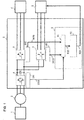
- Fig. 1 is a system configuration diagram of a power conversion device pertaining to a first embodiment of the present invention. Description starts with a basic configuration of the present system.
- a generator 2 is connected to an engine 1 and alternating current (AC) power which is generated by this generator 2 is fed into a power conversion device 3.
- the power conversion device 3 converts the AC power fed into it to a direct current (DC) power through a converter 4 and, through a first inverter (an inverter for driving a motor), converts this DC power to a three-phase AC power to make an AC motor 6 generate motive force for driving a train.
- DC direct current
- AC power is produced by a second inverter 7 (auxiliary power supply device), so that the power is supplied to auxiliary equipment 8, such as an air-conditioning system, a lighting system, and a brake compressor.
- auxiliary equipment 8 has a function of decreasing load a load upon receiving a load decrease instruction from a controller 9 of the power conversion device.
- the controller 9 has a function of exerting an overall control of the system including control of the converter 4, first inverter 5, and second inverter 7 and a protective function that performs stopping and rebooting the system in the event that abnormality such as over-temperature has been found in the converter 4, first inverter 5, or second inverter 7.
- Fig. 1 detail of the function of exerting an overall control of the system including control of the converter 4, first inverter 5, and second inverter 7 and detail of the protective function that performs stopping and rebooting the system upon detection of abnormality of the converter 4, first inverter 5, or second inverter are omitted from depiction. 7.
- the converter 4, first inverter 5, and second inverter 7 of the power conversion device 3 are provided with a temperature sensor which measures the temperature of a switching element and outputs a result of the measurement as element temperature information.
- an element over-temperature detection unit 91 generates an over-temperature detection signal 910 from converter element temperature information 1010, first inverter element temperature information 1020, and second inverter element temperature information 1030 which are pieces of element temperature information from temperature sensors 101, 102, 103 which are mounted on the converter 4, first inverter 5, and second inverter 7, respectively, and outputs that signal to a load decrease instruction creating unit 92.
- Fig. 2 is a diagram illustrating a flowchart of control by the element over-temperature detection unit 91 in Fig. 1 .
- This control flowchart illustrates a basic control flow for creating an over-temperature detection signal 910 from the converter element temperature information 1010, first inverter element temperature information 1020, and second inverter element temperature information 1030 from the temperature sensors 101, 102, 103 in the power conversion device 3.
- the element over-temperature detection unit 91 (hereinafter abbreviated to the "detection unit") starts processing.
- the detection unit determines whether or not the element temperature of the first inverter is equal to or more than a predetermined temperature. If the element temperature of the first inverter is equal to or more than the predetermined temperature (Yes), the detection unit determines over-temperature and sets the over-temperature detection signal 910 ON at step S006, and terminates the processing at step S007. Otherwise, if the element temperature of the first inverter is less than the predetermined temperature at step S002, a transition is made to step S003.
- the detection unit determines whether or not the element temperature from the second inverter is equal to or more than a predetermined temperature. If the element temperature of the second inverter is equal to or more than the predetermined temperature (Yes), the detection unit determines over-temperature and sets the over-temperature detection signal 910 ON at step S006, and terminates the processing at step S007. Otherwise, if the element temperature of the second inverter is less than the predetermined temperature at step S003, a transition is made to step S004.
- the detection unit determines whether or not the element temperature from the converter is equal to or more than a predetermined temperature. If the element temperature of the converter is equal to or more than the predetermined temperature (Yes), the detection unit determines over-temperature and sets the over-temperature detection signal 910 ON at step S006, and terminates the processing at step S007. Otherwise, if the element temperature of the converter is less than the predetermined temperature at step S004, the detection unit determines no over-temperature and sets the over-temperature detection signal 910 OFF at step S005, and terminates the processing at step S007.
- the predetermined temperature should be set lower than the permitted temperature of each element.
- the predetermined temperature should be set to a temperature that is on the order of 60°C to 30°C lower than the permitted temperature. This is because the element temperature that can be measured by a temperature sensor is the temperature of the package of the element and the temperature of the junction of the element is higher than the temperature of the package.
- protection may be actuated to force the power conversion device to stop before an effect of reducing the load and restraining temperature rise works.
- the predetermined temperature may differ for the first inverter, second inverter, and converter.
- processing order of the steps S002, S003, and S004 is not necessarily in the order described in Fig. 2 and the processing order can be changed.
- a part or the whole of the element over-temperature detection unit 91 mentioned above may be implemented by hardware; inter alia, by designing an integrated circuit that is used as a component of the controller 9 to implement it.
- it may be implemented by software in such a way that a processor (not depicted) included in the controller 9 interprets and executes a program that implements respective functions.
- Information such as this program can be stored in a recording device such as a memory, hard disk, and SSD or a recording medium such as an IC card, SD card, and DVD.
- the load decrease instruction creating unit 92 creates a load decrease instruction 920, based on the over-temperature detection signal 910.
- This load decrease instruction 920 differs according to the type of the auxiliary equipment 8. For example, if the auxiliary equipment 8 is an air-conditioning system, an instruction for decreasing the number of air-conditioners to be run is created. If the auxiliary equipment 8 is a lighting system, an instruction for decreasing the number of lighting units to be turned on is created. As a method of inputting this instruction to the auxiliary equipment 8, the instruction may be transmitted with a metallic line or using a control information processing device which is not depicted.
- the element over-temperature detection unit 91 determines whether or not each element is placed in an over-temperature state in excess of a predetermined temperature (on the order of 60°C to 30°C lower than the permitted temperature of the element), based on temperature information from the respective temperature sensors which measure the element temperatures of the first inverter, second inverter, and converter, and the load decrease instruction creating unit 92 outputs a load decrease instruction 920 to the auxiliary equipment 8.
- a load decrease instruction 920 is output to the auxiliary equipment 8 to decrease the number of units of the auxiliary equipment. It is also possible to output a load decrease instruction 920 to the second inverter and control the switching operation of the second inverter to decrease the amount of electric power to be supplied to the auxiliary equipment.
- a generator In a rail vehicle system in which a generator is driven by an engine installed under the floor and electric power output by the generator is converted by a power conversion device also installed under the floor to supply power to a vehicle drive unit, such as a motor, of a train and electric equipment on the vehicle, such as an air-conditioning system, a lighting system, and a battery charger, it may happen that the power conversion device is heated by high temperature exhaust air from the engine and forced to stop by an over-temperature protection. To avoid falling into this situation, by decreasing the electric power output by the second inverter before the over-temperature protection works, it is possible to decrease the engine output and decrease the temperature of the engine exhaust air accordingly. This enables it to restrain rise of the temperature of the power conversion device and reduce the possibility that the power conversion device is forced to stop by the over-temperature protection.
- Fig. 3 is a system configuration diagram of a power conversion device pertaining to a second embodiment of the present invention.
- the second embodiment is such that the temperature of the power conversion device has changed from the temperature of each element, as in the first embodiment described previously, to the temperature inside the device housing.
- a temperature sensor 104 is installed inside the housing of the power conversion device 3 and an intra-housing over-temperature detection unit 93 is provided in the controller 9, which differs from the first embodiment.
- the intra-housing over-temperature detection unit 93 generates an over-temperature detection signal 930 from intra-housing temperature information 1040 from the temperature sensor 104 installed inside the housing of the power conversion device 3 and outputs that signal to the load decrease instruction creating unit 92.
- Fig. 4 is a diagram illustrating a flowchart of control by the intra-housing over-temperature detection unit 93 in Fig. 3 .
- This control flowchart illustrates a basic control flow for creating an over-temperature detection signal 930 from the intra-housing temperature information 1040 from the temperature sensor 104 in the power conversion device 3.
- the intra-housing over-temperature detection unit 93 (hereinafter abbreviated to the "detection unit") starts processing.
- the detection unit determines whether or not the intra-housing temperature is equal to or more than a predetermined temperature. If the intra-housing temperature is equal to or more than the predetermined temperature (Yes), the detection unit determines an over-temperature and sets the over-temperature detection signal 930 ON at step S104, and terminates the processing at step S105.
- the detection unit determines no over-temperature and sets the over-temperature detection signal 930 OFF at step S103, and terminates the processing at step S105.
- the predetermined temperature should be set lower than the permitted temperature of each of the power conversion device components installed inside the housing.
- the predetermined temperature should be set to a temperature that is on the order of 20°C to 10°C lower than the permitted temperature of each component. This is for the sake of avoiding the following situation: if the predetermined temperature is set lower than, but close to the permitted value, protection may be actuated to force the power conversion device to stop before the effect of reducing the load and restraining temperature rise works.
- the intra-housing over-temperature detection unit 93 determines whether or not the power conversion device is placed in an over-temperature state in excess of a predetermined temperature (on the order of 20°C to 10°C lower than the permitted temperature of each of the power conversion device components installed inside the housing), based on temperature information from the temperature sensor which measures the temperature inside the housing of the power conversion device, and the load decrease instruction creating unit 92 outputs a load decrease instruction 920 to the auxiliary equipment 8 or the second inverter.
- a predetermined temperature on the order of 20°C to 10°C lower than the permitted temperature of each of the power conversion device components installed inside the housing
- a power conversion device in a rail vehicle system in which a generator is driven by an engine and electric power output by the generator is converted by a power conversion device to supply power to a vehicle drive unit, such as a motor, of a train and electric equipment on the vehicle, such as an air-conditioning system, a lighting system, and a battery charger, it is possible to reduce the possibility that the power conversion device is heated by high temperature exhaust air from the engine and forced to stop by over-temperature protection.
- Fig. 5 is a system configuration diagram of a power conversion device pertaining to a third embodiment of the present invention.
- the third embodiment is such that the temperature of the power conversion device has changed from the temperature of each element, as in the first embodiment described previously, to the temperature of the controller.
- a temperature sensor 105 is installed in the controller 9 of the power conversion device 3 and a controller over-temperature detection unit 94 is provided in the controller 9, which differs from the first embodiment.
- the controller over-temperature detection unit 94 generates an over-temperature detection signal 940 from controller temperature information 1050 from the temperature sensor 105 installed in the controller 9 and outputs that signal to the load decrease instruction creating unit 92.
- Fig. 6 is a diagram illustrating a flowchart of control by the controller over-temperature detection unit 94 in Fig. 5 .
- This control flowchart illustrates a basic control flow for creating an over-temperature detection signal 940 from the controller temperature information 1050 from the temperature sensor 105 in the power conversion device 3.
- the controller over-temperature detection unit 943 (hereinafter abbreviated to the "detection unit") starts processing.
- the detection unit determines whether or not the controller temperature is equal to or more than a predetermined temperature. If the controller temperature is equal to or more than the predetermined temperature (Yes), the detection unit determines over-temperature and sets the over-temperature detection signal 940 ON at step S204, and terminates the processing at step S205. Otherwise, if the controller temperature is less than the predetermined temperature (No) at step S202, the detection unit determines no over-temperature and sets the over-temperature detection signal 940 OFF at step S203, and terminates the processing at step S205.
- the predetermined temperature should be set lower than the permitted temperature of each of the components of the controller 9.
- the predetermined temperature should be set to a temperature that is on the order of 20°C to 10°C lower than the permitted temperature of each component. If the predetermined temperature is set lower than, but close to the permitted value, protection may be actuated to force the power conversion device to stop before the effect of reducing the load and restraining temperature rise works.
- the controller over-temperature detection unit 94 determines whether or not the controller is placed in an over-temperature state in excess of a predetermined temperature (on the order of 20°C to 10°C lower than the permitted temperature of each of the controller components), based on temperature information from the temperature sensor which measures the temperature of the controller, and the load decrease instruction creating unit 92 outputs a load decrease instruction 920 to the auxiliary equipment 8 or the second inverter.
- a power conversion device in a rail vehicle system in which a generator is driven by an engine and electric power output by the generator is converted by a power conversion device to supply power to a vehicle drive unit, such as a motor, of a train and electric equipment on the vehicle, such as an air-conditioning system, a lighting system, and a battery charger, it is possible to reduce the possibility that the power conversion device is heated by high temperature exhaust air from the engine and forced to stop by over-temperature protection.
- first through third embodiments of the present invention have been described hereinbefore, the configuration of each of these embodiments is definitely exemplary and the present invention may be changed, as appropriate, without departing from the scope of its technical concept.
- first inverter 5, second inverter 7, and converter 4 are controlled by a single controller 9, as described in the first through third embodiments, each of them may be controlled by each respective controller.
- each controller implements detecting over-temperature and a load decrease instruction 920 to the auxiliary equipment 8.
- the first inverter 5, second inverter 7, and converter 4 are installed in one housing, as described, the first inverter 5 and second inverter 7 may, for example, be installed in a separate housing. In this case, again, each controller implements detecting over-temperature and a load decrease instruction 920 to the auxiliary equipment 8.
Landscapes
- Engineering & Computer Science (AREA)
- Mechanical Engineering (AREA)
- Power Engineering (AREA)
- Transportation (AREA)
- Combustion & Propulsion (AREA)
- Chemical & Material Sciences (AREA)
- Sustainable Energy (AREA)
- Life Sciences & Earth Sciences (AREA)
- Sustainable Development (AREA)
- Health & Medical Sciences (AREA)
- Biomedical Technology (AREA)
- General Health & Medical Sciences (AREA)
- Automation & Control Theory (AREA)
- Inverter Devices (AREA)
- Electric Propulsion And Braking For Vehicles (AREA)
Abstract
Description
- The present invention relates to a power conversion device that is mounted in a vehicle.
- A system, as outlined below, for use in a rail vehicle has appeared recently: a generator is driven by an engine and electric power output by the generator is converted by a power conversion device to supply power to a vehicle drive unit, such as a motor, of a train and electric equipment on the vehicle, such as an air-conditioning system, a lighting system, and a battery charger. In most cases, equipment such as the engine, generator, and power conversion device is situated under the floor of the rail vehicle. Consequently, because of high temperature exhaust air of the engine, the temperature of the power conversion device increases more in comparison with an ordinary train system. Also, because a rail vehicle generally runs in both front/back directions, it is difficult that the power conversion device gets away from the influence of the engine exhaust air. In a power conversion device, in order to prevent failure and reduced life span of semiconductor elements for power conversion and a control logic unit due to temperature rise inside the device, temperature sensors are generally provided on the semiconductor elements and the control logic unit and the device has a function of stopping the power conversion device when a value of the temperature sensors has become more than a permitted value. In a system in which electric power is supplied to a power conversion device by an engine and a generator, there is a possibility that the power conversion device is heated by the engine exhaust air and the power conversion device is forced to stop frequently by this stopping function. As a solution to avoid this, a method that decreases the output of a motor that is a load of the power conversion device is described in
Patent Literature 1. - Patent Literature 1: Japanese Unexamined Patent Application Publication No.
2005-269815 - If a control method described in
Patent Literature 1 is applied to a rail vehicle, the output torque would be decreased lower than a desired motor torque and, therefore, this may result in non-fulfillment of train operation as per timetable, causing a train delay. - An object of the present invention is to provide a power conversion device that operates to decrease the output exhaust air temperature of an engine, while maintaining train operation as per timetable, and prevent an emergency stop due to the temperature of a converter or an inverter in excess of a permitted value.
- The present invention is characterized as below: a vehicle power conversion device including a converter which converts alternating current (AC) power generated by a generator which generates electric power by torque of an engine to a direct current (DC) power, a first inverter which converts the DC power to AC power to be supplied to a motor for driving the vehicle, and a second inverter which converts the DC power to AC power to be supplied to auxiliary equipment. The power conversion device includes a first temperature sensor which measures a temperature of the first inverter and a controller which constrains electric power to be output by the second inverter when the temperature of the first inverter measured by the first temperature sensor has become equal to or more than a predetermined temperature.
- According to the present invention, it is possible to decrease the output exhaust air temperature of an engine by constraining electric power that is consumed by auxiliary equipment while maintaining train operation as per timetable, and prevent an emergency stop due to the temperature of a converter or an inverter in excess of a permitted value.
-
-
Fig. 1 is a system configuration diagram of a power conversion device pertaining to a first embodiment of the present invention. -
Fig. 2 is a diagram illustrating a flowchart of control by an element over-temperaturedetection unit 91 in the first embodiment. -
Fig. 3 is a system configuration diagram of a power conversion device pertaining to a second embodiment. -
Fig. 4 is a diagram illustrating a flowchart of control by an intra-housing over-temperaturedetection unit 93 in the second embodiment. -
Fig. 5 is a system configuration diagram of a power conversion device pertaining to a third embodiment. -
Fig. 6 is a diagram illustrating a flowchart of control by a controller over-temperaturedetection unit 94 in the third embodiment. - As embodiments of the present invention, first through third embodiments are described with reference to the drawings. In the respective drawings and the respective embodiments, identical or similar components are assigned identical reference designators and description of duplicated components may be omitted.
-
Fig. 1 is a system configuration diagram of a power conversion device pertaining to a first embodiment of the present invention. Description starts with a basic configuration of the present system. Agenerator 2 is connected to anengine 1 and alternating current (AC) power which is generated by thisgenerator 2 is fed into apower conversion device 3. Thepower conversion device 3 converts the AC power fed into it to a direct current (DC) power through aconverter 4 and, through a first inverter (an inverter for driving a motor), converts this DC power to a three-phase AC power to make anAC motor 6 generate motive force for driving a train. In addition, from the DC power produced by the foregoingconverter 4, AC power is produced by a second inverter 7 (auxiliary power supply device), so that the power is supplied to auxiliary equipment 8, such as an air-conditioning system, a lighting system, and a brake compressor. The auxiliary equipment 8 has a function of decreasing load a load upon receiving a load decrease instruction from acontroller 9 of the power conversion device. Furthermore, in addition to a function of creating a load decrease instruction to the auxiliary equipment 8, thecontroller 9 has a function of exerting an overall control of the system including control of theconverter 4,first inverter 5, andsecond inverter 7 and a protective function that performs stopping and rebooting the system in the event that abnormality such as over-temperature has been found in theconverter 4,first inverter 5, orsecond inverter 7. Now, inFig. 1 , detail of the function of exerting an overall control of the system including control of theconverter 4,first inverter 5, andsecond inverter 7 and detail of the protective function that performs stopping and rebooting the system upon detection of abnormality of theconverter 4,first inverter 5, or second inverter are omitted from depiction. 7. - Then, descriptions are provided as to what processing is performed in the
controller 9 to create a load decrease instruction to the auxiliary equipment 8. Theconverter 4,first inverter 5, andsecond inverter 7 of thepower conversion device 3 are provided with a temperature sensor which measures the temperature of a switching element and outputs a result of the measurement as element temperature information. In thecontroller 9, an element over-temperaturedetection unit 91 generates an over-temperaturedetection signal 910 from converterelement temperature information 1010, first inverterelement temperature information 1020, and second inverterelement temperature information 1030 which are pieces of element temperature information fromtemperature sensors converter 4,first inverter 5, andsecond inverter 7, respectively, and outputs that signal to a load decreaseinstruction creating unit 92. -
Fig. 2 is a diagram illustrating a flowchart of control by the element over-temperaturedetection unit 91 inFig. 1 . This control flowchart illustrates a basic control flow for creating an over-temperaturedetection signal 910 from the converterelement temperature information 1010, first inverterelement temperature information 1020, and second inverterelement temperature information 1030 from thetemperature sensors power conversion device 3. - At step S001, the element over-temperature detection unit 91 (hereinafter abbreviated to the "detection unit") starts processing. At step S002, the detection unit determines whether or not the element temperature of the first inverter is equal to or more than a predetermined temperature. If the element temperature of the first inverter is equal to or more than the predetermined temperature (Yes), the detection unit determines over-temperature and sets the over-temperature
detection signal 910 ON at step S006, and terminates the processing at step S007. Otherwise, if the element temperature of the first inverter is less than the predetermined temperature at step S002, a transition is made to step S003. - At step S003, the detection unit determines whether or not the element temperature from the second inverter is equal to or more than a predetermined temperature. If the element temperature of the second inverter is equal to or more than the predetermined temperature (Yes), the detection unit determines over-temperature and sets the over-temperature
detection signal 910 ON at step S006, and terminates the processing at step S007. Otherwise, if the element temperature of the second inverter is less than the predetermined temperature at step S003, a transition is made to step S004. - At step S004, the detection unit determines whether or not the element temperature from the converter is equal to or more than a predetermined temperature. If the element temperature of the converter is equal to or more than the predetermined temperature (Yes), the detection unit determines over-temperature and sets the over-temperature
detection signal 910 ON at step S006, and terminates the processing at step S007. Otherwise, if the element temperature of the converter is less than the predetermined temperature at step S004, the detection unit determines no over-temperature and sets the over-temperaturedetection signal 910 OFF at step S005, and terminates the processing at step S007. - Here, the predetermined temperature should be set lower than the permitted temperature of each element. In particular, the predetermined temperature should be set to a temperature that is on the order of 60°C to 30°C lower than the permitted temperature. This is because the element temperature that can be measured by a temperature sensor is the temperature of the package of the element and the temperature of the junction of the element is higher than the temperature of the package. Additionally, if the predetermined temperature is set lower than, but close to the permitted value, protection may be actuated to force the power conversion device to stop before an effect of reducing the load and restraining temperature rise works. In addition, if an element that is used differs, the predetermined temperature may differ for the first inverter, second inverter, and converter. Furthermore, processing order of the steps S002, S003, and S004 is not necessarily in the order described in
Fig. 2 and the processing order can be changed. - In addition, a part or the whole of the element over-temperature
detection unit 91 mentioned above may be implemented by hardware; inter alia, by designing an integrated circuit that is used as a component of thecontroller 9 to implement it. In addition, it may be implemented by software in such a way that a processor (not depicted) included in thecontroller 9 interprets and executes a program that implements respective functions. Information such as this program can be stored in a recording device such as a memory, hard disk, and SSD or a recording medium such as an IC card, SD card, and DVD. - Returning to
Fig. 1 , descriptions are provided as to what processing is performed after the over-temperaturedetection signal 910 is set ON. The load decreaseinstruction creating unit 92 creates aload decrease instruction 920, based on the over-temperaturedetection signal 910. - This
load decrease instruction 920 differs according to the type of the auxiliary equipment 8. For example, if the auxiliary equipment 8 is an air-conditioning system, an instruction for decreasing the number of air-conditioners to be run is created. If the auxiliary equipment 8 is a lighting system, an instruction for decreasing the number of lighting units to be turned on is created. As a method of inputting this instruction to the auxiliary equipment 8, the instruction may be transmitted with a metallic line or using a control information processing device which is not depicted. - As described hereinbefore, in the
controller 9 in the first embodiment, the elementover-temperature detection unit 91 determines whether or not each element is placed in an over-temperature state in excess of a predetermined temperature (on the order of 60°C to 30°C lower than the permitted temperature of the element), based on temperature information from the respective temperature sensors which measure the element temperatures of the first inverter, second inverter, and converter, and the load decreaseinstruction creating unit 92 outputs aload decrease instruction 920 to the auxiliary equipment 8. - Now, while the embodiment in which a
load decrease instruction 920 is output to the auxiliary equipment 8 to decrease the number of units of the auxiliary equipment was described with regard toFig. 1 , it is also possible to output aload decrease instruction 920 to the second inverter and control the switching operation of the second inverter to decrease the amount of electric power to be supplied to the auxiliary equipment. - In a rail vehicle system in which a generator is driven by an engine installed under the floor and electric power output by the generator is converted by a power conversion device also installed under the floor to supply power to a vehicle drive unit, such as a motor, of a train and electric equipment on the vehicle, such as an air-conditioning system, a lighting system, and a battery charger, it may happen that the power conversion device is heated by high temperature exhaust air from the engine and forced to stop by an over-temperature protection. To avoid falling into this situation, by decreasing the electric power output by the second inverter before the over-temperature protection works, it is possible to decrease the engine output and decrease the temperature of the engine exhaust air accordingly. This enables it to restrain rise of the temperature of the power conversion device and reduce the possibility that the power conversion device is forced to stop by the over-temperature protection.
-
Fig. 3 is a system configuration diagram of a power conversion device pertaining to a second embodiment of the present invention. The second embodiment is such that the temperature of the power conversion device has changed from the temperature of each element, as in the first embodiment described previously, to the temperature inside the device housing. In the second embodiment, accordingly, atemperature sensor 104 is installed inside the housing of thepower conversion device 3 and an intra-housingover-temperature detection unit 93 is provided in thecontroller 9, which differs from the first embodiment. - The following sets forth what processing is performed in the
controller 9 to create aload decrease instruction 920 to the auxiliary equipment 8 in the second embodiment. In thecontroller 9, the intra-housingover-temperature detection unit 93 generates anover-temperature detection signal 930 fromintra-housing temperature information 1040 from thetemperature sensor 104 installed inside the housing of thepower conversion device 3 and outputs that signal to the load decreaseinstruction creating unit 92. -
Fig. 4 is a diagram illustrating a flowchart of control by the intra-housingover-temperature detection unit 93 inFig. 3 . This control flowchart illustrates a basic control flow for creating anover-temperature detection signal 930 from theintra-housing temperature information 1040 from thetemperature sensor 104 in thepower conversion device 3. - At step S101, the intra-housing over-temperature detection unit 93 (hereinafter abbreviated to the "detection unit") starts processing. At step S102, the detection unit determines whether or not the intra-housing temperature is equal to or more than a predetermined temperature. If the intra-housing temperature is equal to or more than the predetermined temperature (Yes), the detection unit determines an over-temperature and sets the
over-temperature detection signal 930 ON at step S104, and terminates the processing at step S105. Otherwise, if the intra-housing temperature is less than the predetermined temperature (No) at step S102, the detection unit determines no over-temperature and sets theover-temperature detection signal 930 OFF at step S103, and terminates the processing at step S105. - Here, the predetermined temperature should be set lower than the permitted temperature of each of the power conversion device components installed inside the housing. In particular, the predetermined temperature should be set to a temperature that is on the order of 20°C to 10°C lower than the permitted temperature of each component. This is for the sake of avoiding the following situation: if the predetermined temperature is set lower than, but close to the permitted value, protection may be actuated to force the power conversion device to stop before the effect of reducing the load and restraining temperature rise works.
- What processing is performed by the load decrease
instruction creating unit 92 when theover-temperature detection signal 930 has been set ON is the same as for the first embodiment and, therefore, a description on it is omitted. - As described hereinbefore, in the
controller 9 in the second embodiment, the intra-housingover-temperature detection unit 93 determines whether or not the power conversion device is placed in an over-temperature state in excess of a predetermined temperature (on the order of 20°C to 10°C lower than the permitted temperature of each of the power conversion device components installed inside the housing), based on temperature information from the temperature sensor which measures the temperature inside the housing of the power conversion device, and the load decreaseinstruction creating unit 92 outputs aload decrease instruction 920 to the auxiliary equipment 8 or the second inverter. - According to the foregoing system, in a rail vehicle system in which a generator is driven by an engine and electric power output by the generator is converted by a power conversion device to supply power to a vehicle drive unit, such as a motor, of a train and electric equipment on the vehicle, such as an air-conditioning system, a lighting system, and a battery charger, it is possible to reduce the possibility that the power conversion device is heated by high temperature exhaust air from the engine and forced to stop by over-temperature protection.
-
Fig. 5 is a system configuration diagram of a power conversion device pertaining to a third embodiment of the present invention. The third embodiment is such that the temperature of the power conversion device has changed from the temperature of each element, as in the first embodiment described previously, to the temperature of the controller. In the third embodiment, accordingly, a temperature sensor 105 is installed in thecontroller 9 of thepower conversion device 3 and a controllerover-temperature detection unit 94 is provided in thecontroller 9, which differs from the first embodiment. - The following sets forth what processing is performed in the
controller 9 to create aload decrease instruction 920 to the auxiliary equipment 8 in the third embodiment. In thecontroller 9, the controllerover-temperature detection unit 94 generates anover-temperature detection signal 940 fromcontroller temperature information 1050 from the temperature sensor 105 installed in thecontroller 9 and outputs that signal to the load decreaseinstruction creating unit 92. -
Fig. 6 is a diagram illustrating a flowchart of control by the controllerover-temperature detection unit 94 inFig. 5 . This control flowchart illustrates a basic control flow for creating anover-temperature detection signal 940 from thecontroller temperature information 1050 from the temperature sensor 105 in thepower conversion device 3. - At step S201, the controller over-temperature detection unit 943 (hereinafter abbreviated to the "detection unit") starts processing. At step S202, the detection unit determines whether or not the controller temperature is equal to or more than a predetermined temperature. If the controller temperature is equal to or more than the predetermined temperature (Yes), the detection unit determines over-temperature and sets the
over-temperature detection signal 940 ON at step S204, and terminates the processing at step S205. Otherwise, if the controller temperature is less than the predetermined temperature (No) at step S202, the detection unit determines no over-temperature and sets theover-temperature detection signal 940 OFF at step S203, and terminates the processing at step S205. - Here, the predetermined temperature should be set lower than the permitted temperature of each of the components of the
controller 9. In particular, the predetermined temperature should be set to a temperature that is on the order of 20°C to 10°C lower than the permitted temperature of each component. If the predetermined temperature is set lower than, but close to the permitted value, protection may be actuated to force the power conversion device to stop before the effect of reducing the load and restraining temperature rise works. - Although returning to
Fig. 5 , what processing is performed after theover-temperature detection signal 940 is set ON is the same as for the first embodiment and, therefore, a description on it is omitted. - As described hereinbefore, in the
controller 9 in the third embodiment, the controllerover-temperature detection unit 94 determines whether or not the controller is placed in an over-temperature state in excess of a predetermined temperature (on the order of 20°C to 10°C lower than the permitted temperature of each of the controller components), based on temperature information from the temperature sensor which measures the temperature of the controller, and the load decreaseinstruction creating unit 92 outputs aload decrease instruction 920 to the auxiliary equipment 8 or the second inverter. - According to the foregoing system, in a rail vehicle system in which a generator is driven by an engine and electric power output by the generator is converted by a power conversion device to supply power to a vehicle drive unit, such as a motor, of a train and electric equipment on the vehicle, such as an air-conditioning system, a lighting system, and a battery charger, it is possible to reduce the possibility that the power conversion device is heated by high temperature exhaust air from the engine and forced to stop by over-temperature protection.
- While the first through third embodiments of the present invention have been described hereinbefore, the configuration of each of these embodiments is definitely exemplary and the present invention may be changed, as appropriate, without departing from the scope of its technical concept. For example, while the
first inverter 5,second inverter 7, andconverter 4 are controlled by asingle controller 9, as described in the first through third embodiments, each of them may be controlled by each respective controller. In this case, each controller implements detecting over-temperature and aload decrease instruction 920 to the auxiliary equipment 8. In addition, while thefirst inverter 5,second inverter 7, andconverter 4 are installed in one housing, as described, thefirst inverter 5 andsecond inverter 7 may, for example, be installed in a separate housing. In this case, again, each controller implements detecting over-temperature and aload decrease instruction 920 to the auxiliary equipment 8. - 1: Engine, 2: Generator, 3: Power conversion device, 4: Converter, 5: First inverter, 6: AC motor, 7: Second inverter, 8: Auxiliary equipment, 9: Controller, 91: Element over-temperature detection unit, 92: Load decrease instruction creating unit, 93: Intra-housing over-temperature detection unit, 94: Controller over-temperature detection unit, 101, 102, 103, 104, 105: Temperature sensor, 910, 930, 940: Over-temperature detection signal, 920: Load decrease instruction, 1010: Converter element temperature information, 1020: First inverter element temperature information, 1030: Second inverter element temperature information, 1040: Intra-housing temperature information, 1050: Controller temperature information
Claims (6)
- A vehicle power conversion device comprising a converter which converts alternating current (AC) power generated by a generator which generates electric power by torque of an engine to a direct current (DC) power, a first inverter which converts the DC power to AC power to be supplied to a motor for driving the vehicle, and a second inverter which converts the DC power to AC power to be supplied to auxiliary equipment,
the power conversion device comprising:a first temperature sensor which measures a temperature of the first inverter; anda controller which constrains electric power to be output by the second inverter when the temperature of the first inverter measured by the first temperature sensor has become equal to or more than a predetermined temperature. - The vehicle power conversion device according to claim 1, further comprising a second temperature sensor which measures a temperature of the second inverter and a third sensor which measures a temperature of the converter,
wherein the controller constrains electric power to be output by the second inverter when the temperature measured by the second or third temperature sensor has become equal to or more than a predetermined temperature. - The vehicle power conversion device according to claim 1,
wherein the temperature of the first inverter that is measured by the first temperature sensor is a temperature inside a housing of the first inverter. - The vehicle power conversion device according to claim 1,
wherein the temperature of the first inverter that is measured by the first temperature sensor is a temperature of the controller. - The vehicle power conversion device according to any one of claims 1 to 4,
wherein the controller constrains electric power to be output by the second inverter by decreasing the number of operating units of the auxiliary equipment or controlling switching operation of the second inverter when the temperature of the first inverter measured by the first temperature sensor has become equal to or more than a predetermined temperature. - A rail vehicle in which a vehicle power conversion device according to any one of claims 1 to 5 is installed under its floor, further comprising the engine, the generator, the auxiliary equipment, the motor for driving the vehicle,
wherein the engine is installed under the floor.
Applications Claiming Priority (2)
| Application Number | Priority Date | Filing Date | Title |
|---|---|---|---|
| JP2016141008 | 2016-07-19 | ||
| PCT/JP2017/023625 WO2018016275A1 (en) | 2016-07-19 | 2017-06-27 | Vehicle power conversion device and rail vehicle |
Publications (3)
| Publication Number | Publication Date |
|---|---|
| EP3489068A1 true EP3489068A1 (en) | 2019-05-29 |
| EP3489068A4 EP3489068A4 (en) | 2020-03-25 |
| EP3489068B1 EP3489068B1 (en) | 2025-08-13 |
Family
ID=60992157
Family Applications (1)
| Application Number | Title | Priority Date | Filing Date |
|---|---|---|---|
| EP17830795.5A Active EP3489068B1 (en) | 2016-07-19 | 2017-06-27 | Vehicle power conversion device and rail vehicle |
Country Status (4)
| Country | Link |
|---|---|
| EP (1) | EP3489068B1 (en) |
| JP (1) | JP6795594B2 (en) |
| CN (1) | CN109476234B (en) |
| WO (1) | WO2018016275A1 (en) |
Cited By (1)
| Publication number | Priority date | Publication date | Assignee | Title |
|---|---|---|---|---|
| US11728757B2 (en) | 2019-11-07 | 2023-08-15 | Carrier Corporation | System and method for controlling temperature inside electrical and electronics system |
Families Citing this family (1)
| Publication number | Priority date | Publication date | Assignee | Title |
|---|---|---|---|---|
| JP7622258B2 (en) * | 2021-12-28 | 2025-01-27 | 株式会社日立製作所 | Railroad vehicle drive system and driving method for railroad vehicle drive system |
Family Cites Families (16)
| Publication number | Priority date | Publication date | Assignee | Title |
|---|---|---|---|---|
| JP3647767B2 (en) * | 2001-04-25 | 2005-05-18 | 株式会社日立製作所 | Train operation control system |
| JP2003034132A (en) * | 2001-07-23 | 2003-02-04 | Suzuki Motor Corp | Electric vehicle air conditioner |
| JP2003274509A (en) * | 2002-03-15 | 2003-09-26 | Nissan Motor Co Ltd | Power converter |
| CN100999188A (en) * | 2006-12-28 | 2007-07-18 | 奇瑞汽车有限公司 | Cooling system of mixed power vehicle |
| JP4678374B2 (en) * | 2007-01-04 | 2011-04-27 | トヨタ自動車株式会社 | LOAD DEVICE CONTROL DEVICE AND VEHICLE |
| JP5017163B2 (en) * | 2008-04-01 | 2012-09-05 | 株式会社日立製作所 | Railway vehicle drive system |
| JP2009254206A (en) * | 2008-04-10 | 2009-10-29 | Toyota Motor Corp | Power source control system |
| JP5366667B2 (en) * | 2009-06-05 | 2013-12-11 | 株式会社東芝 | Train overall control system |
| WO2012105282A1 (en) * | 2011-01-31 | 2012-08-09 | 株式会社 日立製作所 | Driving system, driving system for railroad-vehicle, and railroad-vehicle and multi-car train mounted with same |
| JP5731234B2 (en) * | 2011-02-25 | 2015-06-10 | Ntn株式会社 | Electric car |
| JP5985816B2 (en) * | 2011-11-30 | 2016-09-06 | 東海旅客鉄道株式会社 | High-speed railway vehicle power conversion system and control method for high-speed railway vehicle power conversion system |
| US9340114B2 (en) * | 2012-01-23 | 2016-05-17 | Ford Global Technologies, Llc | Electric vehicle with transient current management for DC-DC converter |
| JP2014053976A (en) * | 2012-09-05 | 2014-03-20 | Kinki Sharyo Co Ltd | Organized train |
| JP2014187783A (en) * | 2013-03-22 | 2014-10-02 | Toyota Motor Corp | Power converter for electric vehicle |
| JP6069121B2 (en) * | 2013-07-11 | 2017-02-01 | 本田技研工業株式会社 | Vehicle drive control device |
| JP6509760B2 (en) * | 2016-03-01 | 2019-05-08 | 富士電機株式会社 | Power converter |
-
2017
- 2017-06-27 WO PCT/JP2017/023625 patent/WO2018016275A1/en not_active Ceased
- 2017-06-27 JP JP2018528465A patent/JP6795594B2/en active Active
- 2017-06-27 CN CN201780043674.1A patent/CN109476234B/en active Active
- 2017-06-27 EP EP17830795.5A patent/EP3489068B1/en active Active
Cited By (1)
| Publication number | Priority date | Publication date | Assignee | Title |
|---|---|---|---|---|
| US11728757B2 (en) | 2019-11-07 | 2023-08-15 | Carrier Corporation | System and method for controlling temperature inside electrical and electronics system |
Also Published As
| Publication number | Publication date |
|---|---|
| CN109476234A (en) | 2019-03-15 |
| JPWO2018016275A1 (en) | 2019-06-20 |
| EP3489068B1 (en) | 2025-08-13 |
| CN109476234B (en) | 2022-03-15 |
| WO2018016275A1 (en) | 2018-01-25 |
| EP3489068A4 (en) | 2020-03-25 |
| JP6795594B2 (en) | 2020-12-02 |
Similar Documents
| Publication | Publication Date | Title |
|---|---|---|
| US7484377B2 (en) | Method and apparatus for cooling system failure detection | |
| JP5648081B2 (en) | Power converter | |
| CN104736981B (en) | Semiconductor chip temperature estimating device and overtemperature protection system | |
| JP6239020B2 (en) | Control device and control method for electric vehicle | |
| JP6305605B1 (en) | Motor control device | |
| JP7061060B2 (en) | Control circuit, drive system and inverter control method | |
| JP6493259B2 (en) | Temperature monitoring device, temperature monitoring method, information processing program, and recording medium | |
| JP2016005317A (en) | Motor controller with protection means for charging resistor | |
| US12142907B2 (en) | Overcurrent protection device for protecting a consumer arranged in a DC grid | |
| CN113556079B (en) | Motor driving device, motor driving method and computer-readable medium | |
| CN105099325A (en) | Motor control device | |
| EP3489068B1 (en) | Vehicle power conversion device and rail vehicle | |
| EP2965940B1 (en) | Main conversion device for electric vehicle | |
| US12525782B2 (en) | Motor drive device provided with charging control unit | |
| US10444288B2 (en) | Abnormality diagnosing device and abnormality diagnosing method | |
| CN112994583B (en) | Motor driving device | |
| JP6667630B2 (en) | Power converter | |
| CN106183816A (en) | Secondary power system and its method of operation | |
| JP5294953B2 (en) | Control device for three-phase AC electric vehicle and control method for three-phase AC electric vehicle | |
| JP2013226045A (en) | Motor control device | |
| KR101481281B1 (en) | System and method for detecting disconnection of converter input link and power module having the same | |
| KR20180020432A (en) | Power control unit and operating method thereof | |
| JP2024008604A (en) | Battery radiation sound measurement device | |
| CN117175978A (en) | Servo motor dynamic braking method, system, intelligent power module and storage medium | |
| WO2023127145A1 (en) | System, information processing device, method, and program |
Legal Events
| Date | Code | Title | Description |
|---|---|---|---|
| STAA | Information on the status of an ep patent application or granted ep patent |
Free format text: STATUS: THE INTERNATIONAL PUBLICATION HAS BEEN MADE |
|
| PUAI | Public reference made under article 153(3) epc to a published international application that has entered the european phase |
Free format text: ORIGINAL CODE: 0009012 |
|
| STAA | Information on the status of an ep patent application or granted ep patent |
Free format text: STATUS: REQUEST FOR EXAMINATION WAS MADE |
|
| 17P | Request for examination filed |
Effective date: 20190110 |
|
| AK | Designated contracting states |
Kind code of ref document: A1 Designated state(s): AL AT BE BG CH CY CZ DE DK EE ES FI FR GB GR HR HU IE IS IT LI LT LU LV MC MK MT NL NO PL PT RO RS SE SI SK SM TR |
|
| AX | Request for extension of the european patent |
Extension state: BA ME |
|
| DAV | Request for validation of the european patent (deleted) | ||
| DAX | Request for extension of the european patent (deleted) | ||
| A4 | Supplementary search report drawn up and despatched |
Effective date: 20200225 |
|
| RIC1 | Information provided on ipc code assigned before grant |
Ipc: B60L 3/00 20190101AFI20200219BHEP Ipc: B60W 10/30 20060101ALI20200219BHEP Ipc: B60L 1/00 20060101ALI20200219BHEP Ipc: B60L 9/18 20060101ALI20200219BHEP Ipc: B60W 20/50 20160101ALI20200219BHEP Ipc: B60K 6/46 20071001ALI20200219BHEP Ipc: H02M 7/12 20060101ALI20200219BHEP Ipc: H02M 7/48 20070101ALI20200219BHEP Ipc: B61C 7/04 20060101ALI20200219BHEP Ipc: B60W 10/08 20060101ALI20200219BHEP |
|
| STAA | Information on the status of an ep patent application or granted ep patent |
Free format text: STATUS: EXAMINATION IS IN PROGRESS |
|
| 17Q | First examination report despatched |
Effective date: 20211216 |
|
| GRAP | Despatch of communication of intention to grant a patent |
Free format text: ORIGINAL CODE: EPIDOSNIGR1 |
|
| STAA | Information on the status of an ep patent application or granted ep patent |
Free format text: STATUS: GRANT OF PATENT IS INTENDED |
|
| INTG | Intention to grant announced |
Effective date: 20250331 |
|
| GRAS | Grant fee paid |
Free format text: ORIGINAL CODE: EPIDOSNIGR3 |
|
| GRAA | (expected) grant |
Free format text: ORIGINAL CODE: 0009210 |
|
| STAA | Information on the status of an ep patent application or granted ep patent |
Free format text: STATUS: THE PATENT HAS BEEN GRANTED |
|
| AK | Designated contracting states |
Kind code of ref document: B1 Designated state(s): AL AT BE BG CH CY CZ DE DK EE ES FI FR GB GR HR HU IE IS IT LI LT LU LV MC MK MT NL NO PL PT RO RS SE SI SK SM TR |
|
| REG | Reference to a national code |
Ref country code: GB Ref legal event code: FG4D |
|
| REG | Reference to a national code |
Ref country code: CH Ref legal event code: EP |
|
| REG | Reference to a national code |
Ref country code: DE Ref legal event code: R096 Ref document number: 602017091221 Country of ref document: DE |
|
| REG | Reference to a national code |
Ref country code: IE Ref legal event code: FG4D |
|
| REG | Reference to a national code |
Ref country code: NL Ref legal event code: MP Effective date: 20250813 |
|
| PG25 | Lapsed in a contracting state [announced via postgrant information from national office to epo] |
Ref country code: IS Free format text: LAPSE BECAUSE OF FAILURE TO SUBMIT A TRANSLATION OF THE DESCRIPTION OR TO PAY THE FEE WITHIN THE PRESCRIBED TIME-LIMIT Effective date: 20251213 |
|
| PG25 | Lapsed in a contracting state [announced via postgrant information from national office to epo] |
Ref country code: NO Free format text: LAPSE BECAUSE OF FAILURE TO SUBMIT A TRANSLATION OF THE DESCRIPTION OR TO PAY THE FEE WITHIN THE PRESCRIBED TIME-LIMIT Effective date: 20251113 |
|
| REG | Reference to a national code |
Ref country code: LT Ref legal event code: MG9D |
|
| PG25 | Lapsed in a contracting state [announced via postgrant information from national office to epo] |
Ref country code: PT Free format text: LAPSE BECAUSE OF FAILURE TO SUBMIT A TRANSLATION OF THE DESCRIPTION OR TO PAY THE FEE WITHIN THE PRESCRIBED TIME-LIMIT Effective date: 20251215 |
|
| PG25 | Lapsed in a contracting state [announced via postgrant information from national office to epo] |
Ref country code: FI Free format text: LAPSE BECAUSE OF FAILURE TO SUBMIT A TRANSLATION OF THE DESCRIPTION OR TO PAY THE FEE WITHIN THE PRESCRIBED TIME-LIMIT Effective date: 20250813 |
|
| PG25 | Lapsed in a contracting state [announced via postgrant information from national office to epo] |
Ref country code: NL Free format text: LAPSE BECAUSE OF FAILURE TO SUBMIT A TRANSLATION OF THE DESCRIPTION OR TO PAY THE FEE WITHIN THE PRESCRIBED TIME-LIMIT Effective date: 20250813 Ref country code: HR Free format text: LAPSE BECAUSE OF FAILURE TO SUBMIT A TRANSLATION OF THE DESCRIPTION OR TO PAY THE FEE WITHIN THE PRESCRIBED TIME-LIMIT Effective date: 20250813 |
|
| PG25 | Lapsed in a contracting state [announced via postgrant information from national office to epo] |
Ref country code: GR Free format text: LAPSE BECAUSE OF FAILURE TO SUBMIT A TRANSLATION OF THE DESCRIPTION OR TO PAY THE FEE WITHIN THE PRESCRIBED TIME-LIMIT Effective date: 20251114 |
|
| PG25 | Lapsed in a contracting state [announced via postgrant information from national office to epo] |
Ref country code: SE Free format text: LAPSE BECAUSE OF FAILURE TO SUBMIT A TRANSLATION OF THE DESCRIPTION OR TO PAY THE FEE WITHIN THE PRESCRIBED TIME-LIMIT Effective date: 20250813 |
|
| PG25 | Lapsed in a contracting state [announced via postgrant information from national office to epo] |
Ref country code: LV Free format text: LAPSE BECAUSE OF FAILURE TO SUBMIT A TRANSLATION OF THE DESCRIPTION OR TO PAY THE FEE WITHIN THE PRESCRIBED TIME-LIMIT Effective date: 20250813 |
|
| PG25 | Lapsed in a contracting state [announced via postgrant information from national office to epo] |
Ref country code: BG Free format text: LAPSE BECAUSE OF FAILURE TO SUBMIT A TRANSLATION OF THE DESCRIPTION OR TO PAY THE FEE WITHIN THE PRESCRIBED TIME-LIMIT Effective date: 20250813 Ref country code: PL Free format text: LAPSE BECAUSE OF FAILURE TO SUBMIT A TRANSLATION OF THE DESCRIPTION OR TO PAY THE FEE WITHIN THE PRESCRIBED TIME-LIMIT Effective date: 20250813 |
|
| PG25 | Lapsed in a contracting state [announced via postgrant information from national office to epo] |
Ref country code: RS Free format text: LAPSE BECAUSE OF FAILURE TO SUBMIT A TRANSLATION OF THE DESCRIPTION OR TO PAY THE FEE WITHIN THE PRESCRIBED TIME-LIMIT Effective date: 20251113 |
|
| PG25 | Lapsed in a contracting state [announced via postgrant information from national office to epo] |
Ref country code: ES Free format text: LAPSE BECAUSE OF FAILURE TO SUBMIT A TRANSLATION OF THE DESCRIPTION OR TO PAY THE FEE WITHIN THE PRESCRIBED TIME-LIMIT Effective date: 20250813 |
|
| REG | Reference to a national code |
Ref country code: AT Ref legal event code: MK05 Ref document number: 1824341 Country of ref document: AT Kind code of ref document: T Effective date: 20250813 |
|
| PG25 | Lapsed in a contracting state [announced via postgrant information from national office to epo] |
Ref country code: SM Free format text: LAPSE BECAUSE OF FAILURE TO SUBMIT A TRANSLATION OF THE DESCRIPTION OR TO PAY THE FEE WITHIN THE PRESCRIBED TIME-LIMIT Effective date: 20250813 |
|
| PG25 | Lapsed in a contracting state [announced via postgrant information from national office to epo] |
Ref country code: DK Free format text: LAPSE BECAUSE OF FAILURE TO SUBMIT A TRANSLATION OF THE DESCRIPTION OR TO PAY THE FEE WITHIN THE PRESCRIBED TIME-LIMIT Effective date: 20250813 |
|
| PG25 | Lapsed in a contracting state [announced via postgrant information from national office to epo] |
Ref country code: AT Free format text: LAPSE BECAUSE OF FAILURE TO SUBMIT A TRANSLATION OF THE DESCRIPTION OR TO PAY THE FEE WITHIN THE PRESCRIBED TIME-LIMIT Effective date: 20250813 |
|
| PG25 | Lapsed in a contracting state [announced via postgrant information from national office to epo] |
Ref country code: CZ Free format text: LAPSE BECAUSE OF FAILURE TO SUBMIT A TRANSLATION OF THE DESCRIPTION OR TO PAY THE FEE WITHIN THE PRESCRIBED TIME-LIMIT Effective date: 20250813 |
|
| PG25 | Lapsed in a contracting state [announced via postgrant information from national office to epo] |
Ref country code: EE Free format text: LAPSE BECAUSE OF FAILURE TO SUBMIT A TRANSLATION OF THE DESCRIPTION OR TO PAY THE FEE WITHIN THE PRESCRIBED TIME-LIMIT Effective date: 20250813 Ref country code: SK Free format text: LAPSE BECAUSE OF FAILURE TO SUBMIT A TRANSLATION OF THE DESCRIPTION OR TO PAY THE FEE WITHIN THE PRESCRIBED TIME-LIMIT Effective date: 20250813 |