EP3489055A1 - Door beam - Google Patents
Door beam Download PDFInfo
- Publication number
- EP3489055A1 EP3489055A1 EP18206095.4A EP18206095A EP3489055A1 EP 3489055 A1 EP3489055 A1 EP 3489055A1 EP 18206095 A EP18206095 A EP 18206095A EP 3489055 A1 EP3489055 A1 EP 3489055A1
- Authority
- EP
- European Patent Office
- Prior art keywords
- pair
- door beam
- webs
- flanges
- welded part
- Prior art date
- Legal status (The legal status is an assumption and is not a legal conclusion. Google has not performed a legal analysis and makes no representation as to the accuracy of the status listed.)
- Granted
Links
Images


Classifications
-
- B—PERFORMING OPERATIONS; TRANSPORTING
- B60—VEHICLES IN GENERAL
- B60J—WINDOWS, WINDSCREENS, NON-FIXED ROOFS, DOORS, OR SIMILAR DEVICES FOR VEHICLES; REMOVABLE EXTERNAL PROTECTIVE COVERINGS SPECIALLY ADAPTED FOR VEHICLES
- B60J5/00—Doors
- B60J5/04—Doors arranged at the vehicle sides
- B60J5/042—Reinforcement elements
- B60J5/0422—Elongated type elements, e.g. beams, cables, belts or wires
- B60J5/0438—Elongated type elements, e.g. beams, cables, belts or wires characterised by the type of elongated elements
- B60J5/0443—Beams
- B60J5/0444—Beams characterised by a special cross section
-
- B—PERFORMING OPERATIONS; TRANSPORTING
- B21—MECHANICAL METAL-WORKING WITHOUT ESSENTIALLY REMOVING MATERIAL; PUNCHING METAL
- B21C—MANUFACTURE OF METAL SHEETS, WIRE, RODS, TUBES OR PROFILES, OTHERWISE THAN BY ROLLING; AUXILIARY OPERATIONS USED IN CONNECTION WITH METAL-WORKING WITHOUT ESSENTIALLY REMOVING MATERIAL
- B21C23/00—Extruding metal; Impact extrusion
- B21C23/02—Making uncoated products
- B21C23/04—Making uncoated products by direct extrusion
- B21C23/14—Making other products
- B21C23/142—Making profiles
-
- B—PERFORMING OPERATIONS; TRANSPORTING
- B60—VEHICLES IN GENERAL
- B60J—WINDOWS, WINDSCREENS, NON-FIXED ROOFS, DOORS, OR SIMILAR DEVICES FOR VEHICLES; REMOVABLE EXTERNAL PROTECTIVE COVERINGS SPECIALLY ADAPTED FOR VEHICLES
- B60J5/00—Doors
- B60J5/04—Doors arranged at the vehicle sides
- B60J5/042—Reinforcement elements
- B60J5/0422—Elongated type elements, e.g. beams, cables, belts or wires
- B60J5/0438—Elongated type elements, e.g. beams, cables, belts or wires characterised by the type of elongated elements
- B60J5/0443—Beams
-
- B—PERFORMING OPERATIONS; TRANSPORTING
- B60—VEHICLES IN GENERAL
- B60J—WINDOWS, WINDSCREENS, NON-FIXED ROOFS, DOORS, OR SIMILAR DEVICES FOR VEHICLES; REMOVABLE EXTERNAL PROTECTIVE COVERINGS SPECIALLY ADAPTED FOR VEHICLES
- B60J5/00—Doors
- B60J5/04—Doors arranged at the vehicle sides
- B60J5/048—Doors arranged at the vehicle sides characterised by the material
- B60J5/0483—Doors arranged at the vehicle sides characterised by the material lightweight metal, e.g. aluminum, magnesium
-
- C—CHEMISTRY; METALLURGY
- C22—METALLURGY; FERROUS OR NON-FERROUS ALLOYS; TREATMENT OF ALLOYS OR NON-FERROUS METALS
- C22C—ALLOYS
- C22C21/00—Alloys based on aluminium
- C22C21/10—Alloys based on aluminium with zinc as the next major constituent
Definitions
- the present invention relates to a door beam for an automobile formed of an aluminum alloy extrusion of a closed cross-section structure.
- a door beam formed of an aluminum alloy extrusion generally includes a pair of flanges (an outer flange positioned on the outer side in the vehicle body width direction and an inner flange positioned on the inner side in the vehicle body width direction) and a pair of webs connecting the pair of flanges with each other (refer to JP-A No. 2006-233336 ).
- the door beam has a closed cross-section structure that is formed by these pairs of the flanges and the webs.
- the aluminum alloy extrusion of such a closed cross-section structure is manufactured using a hollow die such as a porthole die, a bridge die, and a spider die.
- a porthole die combining a mandrel body and a die is used, the mandrel body including plural portholes.
- An aluminum billet pressed into the porthole die is divided by the portholes, thereafter surrounds the mandrel to be welded and integrated again, and becomes an extrusion of a closed cross-section structure with the inner surface being formed by the mandrel and with the outer surface being formed by the die.
- a welded part exists inevitably.
- the structure is different between the welded part and the portions other than the welded part (normal part), and such a fact becomes a problem that the mechanical property for example the rupture limit of the welded part is lower compared to the normal part.
- low rupture limit of the welded part possibly causes drop of the strength and the energy absorption amount of the door beam as an energy absorption member.
- the object of the present invention is to be not likely to cause rupture at the time of collision in a door beam formed of such an aluminum alloy extrusion of the closed cross-section structure having the welded part.
- An embodiment of the door beam related to the present invention is formed of an aluminum alloy extrusion of a closed cross-section structure having a welded part along the longitudinal direction (extruding direction) and includes a pair of flanges positioned on the inner side and the outer side in the vehicle body width direction and a pair of webs connecting the pair of flanges with each other, and the welded part is arranged in the pair of flanges and is not arranged in the webs.
- the welded part in the pair of flanges and not arranging the welded part in the pair of the webs, such an event can be avoided that the welded part becomes a point of origin of deformation in the buckling deformation of the web at the time of a collision, and thereby rupture of the webs comes to be not likely to occur at the time of a collision.
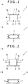
- FIG. 1A and FIG. 1B First, an embodiment of the door beam related to the present invention will be explained referring to FIG. 1A and FIG. 1B .
- a door beam 1 illustrated in FIG. 1A is formed of an aluminum alloy extrusion of a closed cross-section structure having a welded part along the longitudinal direction (extruding direction).
- the door beam 1 is straight in the longitudinal direction, and includes a pair of flanges (an inner flange 2, an outer flange 3) positioned on the inner side and the outer side in the vehicle body width direction and a pair of webs 4, 5 connecting the pair of flanges with each other.
- Each of the inner flange-2 and the outer flange 3 includes portions (protruding flanges 2a, 2b, 3a, 3b) protruding outward from joint sections with a pair of the webs 4, 5.
- Both of a pair of the flanges 2, 3 and a pair of the webs 4, 5 have a flat plate shape, and are formed to be substantially orthogonal to each other.
- one or more intermediate ribs may be arranged between a pair of the webs 4, 5.
- the protruding flanges 2a, 2b, 3a, 3b are arranged at both ends of a pair of the flanges 2, 3 respectively, however, this point is not indispensable, and the door beam 1 may has such a cross-sectional shape that the protrusion flange is not arranged in one or both of the flanges.
- welded parts 6, 7 are formed in a pair of the flanges 2, 3.
- the welded parts 6, 7 are formed along the longitudinal direction of the door beam 1 (the extruding direction of the aluminum alloy extrusion).
- the position of the welded parts 6, 7 in the width direction of a pair of the flanges 2, 3 is not particularly limited. However, from a viewpoint of preventing the welded parts 6, 7 from becoming a point of origin of occurrence of breakage at the time of a collision, it is preferable that the position of the welded parts 6, 7 is between the web 4 and the web 5 avoiding the joint part of the flanges 2, 3 and the webs 4, 5, and the center part of the web 4 and the web 5 (such a position that the distance from the web 4 is substantially the same as the distance from the web 5) as illustrated in FIG. 1A is more preferable.
- the position of the welded part is between the web 4 and the web 5 (between the web 4 and the intermediate rib and/or between the web 5 and the intermediate rib) avoiding the joint part of the intermediate rib and the flanges 2, 3.
- the aluminum alloy extrusion of a closed cross-section structure which is a raw material of the door beam 1 is manufactured using a hollow die such as a porthole die, a bridge die, and a spider die.
- the welded parts 6, 7 described above are formed by that the metal flow is once divided inside the hollow die and are integrated thereafter, exist along the longitudinal direction (the extruding direction) of the aluminum alloy extrusion, and have a micro-structure different from that of a portion (the normal part) other than the welded part.
- FIG. 2A illustrates a cross-sectional view of a door beam 11 (conventional material) having a form different from that of the door beam 1 ( FIG. 1A ) related to the present disclosure.
- a door beam 11 conventional material
- FIG. 2A portions substantially the same as those of the door beam 1 of FIG. 1A are marked with the same reference signs.
- the door beam 11 is formed of an aluminum alloy extrusion of a closed cross-section structure having a welded part along the longitudinal direction (extruding direction), and has a closed cross-section structure substantially the same as that of the door beam 1.
- welded parts 16, 17 are formed in a pair of the webs 4, 5 differently from the door beam 1.
- the welded parts 16, 17 are formed along the longitudinal direction of the door beam 1 (the extruding direction of the aluminum alloy extrusion) similarly to the welded parts 6, 7 of the door beam 1.
- the door beam receives the collision load, it is required to increase the energy absorption amount.
- it is required to make the web buckle so that the flange on the inner side in the vehicle width direction (the back side of the collision) is not broken and to relax the tensile strain generated in the flange on the inner side in the vehicle width direction particularly in the stage of the latter half of the collision.
- the web buckles the web is bendingly deformed around its middle region in the vehicle width direction, and the strain is concentrated locally to this region.
- the welded parts 16, 17 are formed in a pair of the webs 4, 5 to which the strain is liable to concentrate. Therefore, in the stage of the latter half of the collision (refer to FIG. 2B ), a pair of the webs 4, 5 bucklingly deforms in the early stage, which is originated from the welded parts 16, 17, or the webs 4, 5 are liable to be easily broken in the welded parts 16, 17, and the energy absorption performance from then onward deteriorates.
- the welded parts 6, 7 are not formed in a pair of the webs 4, 5. Therefore, in the stage of the latter half of a collision (refer to FIG. 1B ), such an event is avoided that the welded parts 6, 7 become a point of origin of the buckling deformation of a pair of the webs 4, 5, rupture of a pair of the webs 4, 5 comes to hardly occur, and thereby deterioration of the energy absorption performance can be prevented.
- a door beam may be subjected to bend forming (so-called large radius bending) in the longitudinal direction, and may thereby have a shape of being curved so as to be convex to the outer side in the vehicle body width direction (refer to FIG. 5 (b) of JP-A No. 2015-147490 for example).
- bend forming small radius bending
- the cross-section structure illustrated in FIG. 1A and FIG. 1B is suitable to be applied to a door beam that is subjected to such bend forming.
- the residual stress distribution within the door beam generally becomes such a one as illustrates by the solid line in FIG. 4 .
- Xc is the neutral axis of bending
- the right side of the axis Y is for the tensile stress
- the left side is for the compressive stress.
- the residual tensile stress becomes the maximum at a position slightly closer to the outer flange 3 from the neutral axis Xc.
- the residual stress distribution within the door beam generally becomes such a one as illustrated by the broken line in FIG. 4 . Since the neutral axis Xc of bending moves to the inner flange 2 side by a tensile force, the residual tensile stress becomes the maximum at a position closer to the inner flange 2 side compared to the case of the simple bending. In any event, within the door beam having been subjected to bend forming, a large tensile stress remains in a generally center region in the vehicle width direction of the webs 4, 5.
- the welded part In an aluminum alloy extrusion of a closed cross-section structure, the welded part is more liable to cause stress corrosion cracking compared to a portion other than the welded part (the normal part).
- the stress corrosion cracking is liable to occur in the region.
- the welded parts 6, 7 (refer to FIG. 1A ) where the stress corrosion cracking is liable to occur are not formed in the webs 4, 5 where a high tensile stress remains by bend forming.
- the stress corrosion cracking is less likely to occur in the webs 4, 5 compared to the door beam where the welded parts 16, 17 (refer to FIG. 2A ) are formed in the webs 4, 5, and therefore it is also possible to perform tougher bend forming.
- a door beam may be subjected to a pressing work (crushing work) at least in a part of the longitudinal direction, and may thereby include a crushing work section where the gap between a pair of the flanges becomes narrow in a part of the longitudinal direction.
- the cross-section structure illustrated in FIG. 1A and FIG. 1B is suitable to be applied to a door beam that is subjected to such bend forming.
- the aluminum alloy extrusion that is a raw material of the door beam is not particularly limited, a 7000-series aluminum alloy extrusion having a high strength which is lower in the rupture limit and is liable to cause a problem of the stress corrosion cracking compared to the 6000-series aluminum alloy extrusion can be employed suitably.
- the composition of the 7000-series aluminum alloy the composition specified in JIS or AA Standards can be applied.
- compositions including Zn: 3-8 mass%, Mg: 0.4-2.5 mass%, Cu: 0.05 to 2.0 mass%, and Ti: 0.005 to 0.2 mass%, further including one kind or more out of Mn: 0.01 to 0.3 mass%, Cr: 0.01 to 0.3 mass%, and Zr: 0.01 to 0.3 mass% with the remainder including Al and impurities.
Abstract
Description
- The present invention relates to a door beam for an automobile formed of an aluminum alloy extrusion of a closed cross-section structure.
- A door beam formed of an aluminum alloy extrusion generally includes a pair of flanges (an outer flange positioned on the outer side in the vehicle body width direction and an inner flange positioned on the inner side in the vehicle body width direction) and a pair of webs connecting the pair of flanges with each other (refer to
JP-A No. 2006-233336 - The aluminum alloy extrusion of such a closed cross-section structure is manufactured using a hollow die such as a porthole die, a bridge die, and a spider die. For example, in the extrusion method using a porthole die, a porthole die combining a mandrel body and a die is used, the mandrel body including plural portholes. An aluminum billet pressed into the porthole die is divided by the portholes, thereafter surrounds the mandrel to be welded and integrated again, and becomes an extrusion of a closed cross-section structure with the inner surface being formed by the mandrel and with the outer surface being formed by the die. Thus, in the aluminum alloy extrusion of the closed cross-section structure manufactured using the hollow die, a welded part exists inevitably.
- With respect to the aluminum alloy extrusion having the welded part, the structure is different between the welded part and the portions other than the welded part (normal part), and such a fact becomes a problem that the mechanical property for example the rupture limit of the welded part is lower compared to the normal part. In the door beam formed of an aluminum alloy extrusion, low rupture limit of the welded part possibly causes drop of the strength and the energy absorption amount of the door beam as an energy absorption member.
- On the other hand, with respect to an aluminum alloy extrusion of a closed cross-section structure having a welded part, improvement of the mechanical property of the welded part by improving the material composition and the manufacturing condition has been studied as described for example in
JP-A No. Heisei 10-306338 JP-A No. 2003-154407 JP-A No. 2007-231408 JP-A No. 2009-045672 - However, even with such an improvement of the material composition and the manufacturing condition, it is hard to equalize the mechanical property of the welded part and the normal part of the aluminum alloy extrusion.
- The object of the present invention is to be not likely to cause rupture at the time of collision in a door beam formed of such an aluminum alloy extrusion of the closed cross-section structure having the welded part.
- An embodiment of the door beam related to the present invention is formed of an aluminum alloy extrusion of a closed cross-section structure having a welded part along the longitudinal direction (extruding direction) and includes a pair of flanges positioned on the inner side and the outer side in the vehicle body width direction and a pair of webs connecting the pair of flanges with each other, and the welded part is arranged in the pair of flanges and is not arranged in the webs.
- In an embodiment of the door beam related to the present invention, by arranging the welded part in the pair of flanges and not arranging the welded part in the pair of the webs, such an event can be avoided that the welded part becomes a point of origin of deformation in the buckling deformation of the web at the time of a collision, and thereby rupture of the webs comes to be not likely to occur at the time of a collision.
-
-
FIG. 1A is an initial cross-section structure in an embodiment of a door beam related to the present invention; -
FIG. 1B is a cross-section structure bendingly deformed due to a collision in an embodiment of the door beam related to the present invention; -
FIG. 2A is an initial cross-section structure in another embodiment of the door beam; -
FIG. 2B is a cross-section structure bendingly deformed due to a collision in another embodiment of the door beam; -
FIG. 3A illustrates a shape of the door beam in the stage of the first half of a collision; -
FIG. 3B illustrates a shape of the door beam in the stage of the latter half of the collision; and -
FIG. 4 is a drawing that schematically illustrates the residual stress distribution in a cross section of the door beam bent to have a large radius. - First, an embodiment of the door beam related to the present invention will be explained referring to
FIG. 1A and FIG. 1B . - A
door beam 1 illustrated inFIG. 1A is formed of an aluminum alloy extrusion of a closed cross-section structure having a welded part along the longitudinal direction (extruding direction). Thedoor beam 1 is straight in the longitudinal direction, and includes a pair of flanges (aninner flange 2, an outer flange 3) positioned on the inner side and the outer side in the vehicle body width direction and a pair ofwebs outer flange 3 includes portions (protrudingflanges webs flanges webs - Also, one or more intermediate ribs may be arranged between a pair of the
webs door beam 1 illustrated inFIG. 1A , theprotruding flanges flanges door beam 1 may has such a cross-sectional shape that the protrusion flange is not arranged in one or both of the flanges. - In this
door beam 1, weldedparts flanges welded parts - The position of the
welded parts flanges welded parts welded parts web 4 and theweb 5 avoiding the joint part of theflanges webs web 4 and the web 5 (such a position that the distance from theweb 4 is substantially the same as the distance from the web 5) as illustrated inFIG. 1A is more preferable. When the intermediate rib is arranged, in a similar manner, it is preferable that the position of the welded part is between theweb 4 and the web 5 (between theweb 4 and the intermediate rib and/or between theweb 5 and the intermediate rib) avoiding the joint part of the intermediate rib and theflanges - The aluminum alloy extrusion of a closed cross-section structure which is a raw material of the
door beam 1 is manufactured using a hollow die such as a porthole die, a bridge die, and a spider die. Thewelded parts -
FIG. 2A illustrates a cross-sectional view of a door beam 11 (conventional material) having a form different from that of the door beam 1 (FIG. 1A ) related to the present disclosure. In the door beam 11 ofFIG. 2A , portions substantially the same as those of thedoor beam 1 ofFIG. 1A are marked with the same reference signs. - The door beam 11 is formed of an aluminum alloy extrusion of a closed cross-section structure having a welded part along the longitudinal direction (extruding direction), and has a closed cross-section structure substantially the same as that of the
door beam 1. - However, in this door beam 11, welded
parts webs door beam 1. Thewelded parts welded parts door beam 1. - When a collision load P is applied to the
door beam 1, 11, in thedoor beam 1, 11, a bending deformation around a rotation axis of the vehicle body vertical direction occurs, at the stage of the first half of a collision (refer toFIG. 3A ), a tensile strain is generated in theinner flange 2 and a compressive strain is generated in theouter flange 3. Subsequently, in the stage of the latter half of the collision (refer toFIG. 3A ), thewebs - Since the door beam receives the collision load, it is required to increase the energy absorption amount. In order to secure a high energy absorption amount, it is required to make the web buckle so that the flange on the inner side in the vehicle width direction (the back side of the collision) is not broken and to relax the tensile strain generated in the flange on the inner side in the vehicle width direction particularly in the stage of the latter half of the collision. When the web buckles, the web is bendingly deformed around its middle region in the vehicle width direction, and the strain is concentrated locally to this region. Also, when the welded part where the rupture limit is low is arranged in the web, such problem possibly occurs that, in the stage of the latter half of the collision, the web bucklingly deforms promptly originated from the welded part or the welded part is liable to be easily broken, and that the energy absorption performance from then onward deteriorates.
- In the case of the door beam 11, the welded
parts webs FIG. 2B ), a pair of thewebs parts webs parts - On the other hand, in the case of the
door beam 1, the weldedparts webs FIG. 1B ), such an event is avoided that the weldedparts webs webs - In the
door beam 1, since the weldedparts flanges parts webs flanges parts flanges flanges parts parts parts parts - As another embodiment of the door beam related to the present invention, a door beam may be subjected to bend forming (so-called large radius bending) in the longitudinal direction, and may thereby have a shape of being curved so as to be convex to the outer side in the vehicle body width direction (refer to FIG. 5 (b) of
JP-A No. 2015-147490 FIG. 1A and FIG. 1B is suitable to be applied to a door beam that is subjected to such bend forming. - When the bending work is simple bending (the bending work without applying a tensile force in the longitudinal direction) and the door beam has a shape of being curved so as to be convex to the outer side in the vehicle body width direction, the residual stress distribution within the door beam generally becomes such a one as illustrates by the solid line in
FIG. 4 . Here, Xc is the neutral axis of bending, the right side of the axis Y is for the tensile stress, and the left side is for the compressive stress. The residual tensile stress becomes the maximum at a position slightly closer to theouter flange 3 from the neutral axis Xc. When bend forming is tensile bending, the residual stress distribution within the door beam generally becomes such a one as illustrated by the broken line inFIG. 4 . Since the neutral axis Xc of bending moves to theinner flange 2 side by a tensile force, the residual tensile stress becomes the maximum at a position closer to theinner flange 2 side compared to the case of the simple bending. In any event, within the door beam having been subjected to bend forming, a large tensile stress remains in a generally center region in the vehicle width direction of thewebs - In an aluminum alloy extrusion of a closed cross-section structure, the welded part is more liable to cause stress corrosion cracking compared to a portion other than the welded part (the normal part). When such welded part exists in the substantially center region in the vehicle width direction described above of the
webs parts 6, 7 (refer toFIG. 1A ) where the stress corrosion cracking is liable to occur are not formed in thewebs webs parts 16, 17 (refer toFIG. 2A ) are formed in thewebs - As still another embodiment of the door beam related to the present invention, a door beam may be subjected to a pressing work (crushing work) at least in a part of the longitudinal direction, and may thereby include a crushing work section where the gap between a pair of the flanges becomes narrow in a part of the longitudinal direction. The cross-section structure illustrated in
FIG. 1A and FIG. 1B is suitable to be applied to a door beam that is subjected to such bend forming. - In a position having received the crushing work (the crushing work section), a pair of the
webs flanges webs 4, 5 (refer toJP-A No. 2014-145119 parts 6, 7 (refer toFIG. 1A ) are not formed in a pair of thewebs webs FIG. 2A ) where the weldedparts webs parts webs - In order to secure a high strength in the bending deformation around the rotation axis of the vehicle body vertical direction of the stage of the first half of a collision in each embodiment described above (refer to
FIG. 1A ) of the door beam related to the present invention, it is more effective to increase the thickness of a pair of theflanges webs flanges webs - Although the aluminum alloy extrusion that is a raw material of the door beam is not particularly limited, a 7000-series aluminum alloy extrusion having a high strength which is lower in the rupture limit and is liable to cause a problem of the stress corrosion cracking compared to the 6000-series aluminum alloy extrusion can be employed suitably. As the composition of the 7000-series aluminum alloy, the composition specified in JIS or AA Standards can be applied. As a preferable composition, there can be cited a composition including Zn: 3-8 mass%, Mg: 0.4-2.5 mass%, Cu: 0.05 to 2.0 mass%, and Ti: 0.005 to 0.2 mass%, further including one kind or more out of Mn: 0.01 to 0.3 mass%, Cr: 0.01 to 0.3 mass%, and Zr: 0.01 to 0.3 mass% with the remainder including Al and impurities.
Claims (7)
- A door beam formed of an aluminum alloy extrusion of a closed cross-section structure having a welded part along the longitudinal direction, comprising:a pair of flanges positioned on the inner side and the outer side in the vehicle body width direction; anda pair of webs connecting the pair of flanges to each other, whereinthe welded part is arranged in the pair of flanges and is not arranged in the pair of webs.
- The door beam according to claim 1, wherein
the welded part is arranged between the pair of webs. - The door beam according to claim 1 or 2, wherein
an intermediate rib connecting the pair of flanges to each other is arranged between the pair of webs, and
the welded part is not arranged in the intermediate rib. - The door beam according to claim 1 or 2, wherein
the welded part is arranged in a center part that is located between the pair of webs. - The door beam according to any one of claims 1 to 4 subjected to bend forming along the longitudinal direction and curved so as to be convex to the outer side in the vehicle body width direction.
- The door beam according to any one of claims 1 to 5, wherein
a crushing work section where the distance of a pair of the flanges is narrowed is provided in a part of the longitudinal direction. - The door beam according to any one of claims 1 to 6 formed of a 7000-series aluminum alloy extrusion.
Applications Claiming Priority (1)
| Application Number | Priority Date | Filing Date | Title |
|---|---|---|---|
| JP2017225001A JP6322329B1 (en) | 2017-11-22 | 2017-11-22 | Door beam |
Publications (2)
| Publication Number | Publication Date |
|---|---|
| EP3489055A1 true EP3489055A1 (en) | 2019-05-29 |
| EP3489055B1 EP3489055B1 (en) | 2021-03-10 |
Family
ID=62107338
Family Applications (1)
| Application Number | Title | Priority Date | Filing Date |
|---|---|---|---|
| EP18206095.4A Revoked EP3489055B1 (en) | 2017-11-22 | 2018-11-14 | Door beam |
Country Status (4)
| Country | Link |
|---|---|
| US (2) | US20190152304A1 (en) |
| EP (1) | EP3489055B1 (en) |
| JP (1) | JP6322329B1 (en) |
| CN (1) | CN109808466B (en) |
Cited By (2)
| Publication number | Priority date | Publication date | Assignee | Title |
|---|---|---|---|---|
| EP3572256A1 (en) * | 2018-04-24 | 2019-11-27 | Kabushiki Kaisha Kobe Seiko Sho (Kobe Steel, Ltd.) | Door beam |
| US11318899B2 (en) * | 2018-05-08 | 2022-05-03 | Kobe Steel, Ltd. | Bumper reinforcement |
Families Citing this family (2)
| Publication number | Priority date | Publication date | Assignee | Title |
|---|---|---|---|---|
| JP7210330B2 (en) * | 2019-03-01 | 2023-01-23 | 株式会社神戸製鋼所 | Aluminum alloy member |
| JP7187120B2 (en) * | 2019-05-22 | 2022-12-12 | 株式会社神戸製鋼所 | Aluminum alloy door beam |
Citations (12)
| Publication number | Priority date | Publication date | Assignee | Title |
|---|---|---|---|---|
| JPS61266123A (en) * | 1985-05-22 | 1986-11-25 | Showa Alum Corp | Production of aluminum shape material |
| JPH06220880A (en) * | 1993-01-28 | 1994-08-09 | Komatsu Ltd | Boom structure for construction machine |
| JPH06220881A (en) * | 1993-01-28 | 1994-08-09 | Komatsu Ltd | Boom structure for construction machine or the like |
| JPH10306338A (en) | 1997-04-28 | 1998-11-17 | Sumitomo Light Metal Ind Ltd | Hollow extruded material of al-cu-mg-si alloy, excellent in strength and corrosion resistance, and its manufacture |
| JP2002309607A (en) * | 2001-04-18 | 2002-10-23 | Komatsu Ltd | Boom and arm of working machine of hydraulic excavator |
| JP2003154407A (en) | 2001-11-19 | 2003-05-27 | Honda Motor Co Ltd | Aluminum extruded material for hydroforming and method of manufacturing the same |
| JP2006233336A (en) | 2006-03-22 | 2006-09-07 | Kobe Steel Ltd | Method for producing automobile energy absorbing member |
| JP2007231408A (en) | 2006-03-03 | 2007-09-13 | Kobe Steel Ltd | Aluminum alloy hollow extruded shape material for tube expansion forming and aluminum alloy hollow member |
| JP2009045672A (en) | 2008-11-20 | 2009-03-05 | Honda Motor Co Ltd | Method of hydroforming hollow aluminum extruded material |
| JP2011177765A (en) * | 2010-03-02 | 2011-09-15 | Kobe Steel Ltd | Structural member |
| JP2014145119A (en) | 2013-01-30 | 2014-08-14 | Kobe Steel Ltd | 7000 series aluminum alloy member excellent in stress corrosion crack resistance and its manufacturing method |
| JP2015147490A (en) | 2014-02-06 | 2015-08-20 | 株式会社神戸製鋼所 | Door beam made of aluminum alloy extruded material |
Family Cites Families (63)
| Publication number | Priority date | Publication date | Assignee | Title |
|---|---|---|---|---|
| US2734117A (en) * | 1956-02-07 | randall | ||
| US2508032A (en) * | 1945-12-22 | 1950-05-16 | Benjamin H Kennedy | Structural metal member |
| US2626024A (en) * | 1947-06-12 | 1953-01-20 | Eric S Persson | Sash of metal profiles for windows and doors |
| US2718289A (en) * | 1950-02-03 | 1955-09-20 | Nat Steel Corp | Nailable structural member |
| US2728587A (en) * | 1950-02-14 | 1955-12-27 | Midland Steel Prod Co | Automobile frame box-section side rail |
| US2975874A (en) * | 1958-04-01 | 1961-03-21 | Pagan Alberto | Girder made up of structural members |
| US4002000A (en) * | 1975-06-30 | 1977-01-11 | Palmer-Shile Company | Beam construction and method of manufacture |
| DE3606024A1 (en) | 1986-02-25 | 1987-08-27 | Aluminium Walzwerke Singen | VEHICLE DOOR WITH IMPACT PROFILE |
| US4760682A (en) * | 1987-05-05 | 1988-08-02 | S & K Enterprises Inc. | Tubular rack beam and method of making same |
| US5205098A (en) * | 1992-06-11 | 1993-04-27 | Landis Donald H | Long-span decking panel |
| US5464302A (en) * | 1993-08-23 | 1995-11-07 | National Gypsum Company | Extendible interconnected C-studs |
| JPH07227618A (en) * | 1994-02-21 | 1995-08-29 | Kobe Steel Ltd | Al alloy extrudate having excellent bending workability |
| US5507522A (en) * | 1994-03-03 | 1996-04-16 | The Budd Company | Hybrid frame rail |
| US5442885A (en) * | 1994-04-15 | 1995-08-22 | A. O. Smith Corporation | Pre-assembly attachment system for a box-section frame member and method of assembling |
| JP2886467B2 (en) * | 1994-11-17 | 1999-04-26 | 株式会社アルテス | Connection structure of steel column and steel beam with closed section |
| US20020005022A1 (en) * | 1997-06-30 | 2002-01-17 | Matthews Leroy | Sheet material attachment system |
| US5881508A (en) * | 1997-10-15 | 1999-03-16 | Materials International, Inc. | Decking extrusion |
| JP3266099B2 (en) | 1998-03-27 | 2002-03-18 | 株式会社神戸製鋼所 | Aluminum alloy door beam |
| US6698155B2 (en) * | 1999-12-27 | 2004-03-02 | Jose Miguel Menendez | Building elements and building element assemblies formed therewith |
| JP2002001535A (en) * | 2000-06-16 | 2002-01-08 | Mitsubishi Heavy Ind Ltd | Automatic welding device |
| AUPR247001A0 (en) * | 2001-01-11 | 2001-02-01 | Scallan, Patrick Joseph | On site moulding of concrete walls suitable for the building industry and other industries |
| US7155874B2 (en) * | 2001-02-15 | 2007-01-02 | Dae-Jun Lee | Tubular structure and modular building assembly using the same |
| KR100427405B1 (en) * | 2001-03-07 | 2004-04-17 | 박재만 | Pssc complex girder |
| US20020139079A1 (en) * | 2001-03-29 | 2002-10-03 | Brady Todd A. | Clip framing system |
| US6802170B2 (en) * | 2002-01-07 | 2004-10-12 | Kurt K. Davis | Box beam and method for fabricating same |
| JP4028759B2 (en) * | 2002-06-05 | 2007-12-26 | 積水化学工業株式会社 | Steel structure and column / beam connection structure |
| US6938392B2 (en) * | 2002-08-14 | 2005-09-06 | Newmark International, Inc. | Concrete filled pole |
| MXPA04000616A (en) * | 2003-01-21 | 2004-07-28 | Rojas Ubilla Jose | Fabrication system for structures light members. |
| JP4388340B2 (en) * | 2003-10-03 | 2009-12-24 | 新日本製鐵株式会社 | Strength members for automobiles |
| US20050279049A1 (en) * | 2004-06-22 | 2005-12-22 | Mackenzie Steven K | Internally reinforced hydroformed assembly and method of making same |
| JP2006007911A (en) * | 2004-06-24 | 2006-01-12 | Nippon Steel Corp | Reinforcing member for automobile |
| US20060005503A1 (en) * | 2004-07-07 | 2006-01-12 | Jeffrey Bladow | Reinforced structural member and method for its manufacture |
| DE602005008141D1 (en) * | 2004-07-28 | 2008-08-28 | Nissan Motor | Preform, hydroforming and hydroforming molded product |
| DE102004049949C5 (en) * | 2004-10-13 | 2009-04-02 | Benteler Automobiltechnik Gmbh | Structural component for the body or a chassis of a motor vehicle |
| US20070074480A1 (en) * | 2005-08-18 | 2007-04-05 | Jude Kleila | Beam and joints for use in screened enclosure and method for designing screened enclosure |
| US8484930B2 (en) * | 2005-11-01 | 2013-07-16 | Phillip C. Ruehl | Boxed frame member and method for manufacture |
| US20070113506A1 (en) * | 2005-11-04 | 2007-05-24 | Denadel Ronald T | Thermally insulated stud and methods for producing the same |
| JP4754386B2 (en) * | 2006-03-30 | 2011-08-24 | 株式会社神戸製鋼所 | Manufacturing method of closed cross-section structural member |
| US20080028721A1 (en) * | 2006-08-04 | 2008-02-07 | Byron James Daniels | Structural column and process for making the same |
| JP2008120319A (en) * | 2006-11-15 | 2008-05-29 | Toyota Motor Corp | Door structure |
| KR101097018B1 (en) | 2007-03-30 | 2011-12-20 | 가부시키가이샤 고베 세이코쇼 | Automobile door with strengthened side collision performance |
| CN101970142B (en) * | 2008-01-14 | 2014-05-28 | 韩国生产技术研究院 | Forming device for thixoextrusion and method thereof |
| US8322750B2 (en) * | 2009-04-02 | 2012-12-04 | Ez Loader Custom Boat Trailers, Inc. | Trailer incorporating a beam structure |
| US20110036051A1 (en) * | 2009-08-14 | 2011-02-17 | Callahan Robert M | Reinforced girder |
| US20110036050A1 (en) * | 2009-08-14 | 2011-02-17 | Robert M Callahan | Reinforced girder |
| JP2011089294A (en) * | 2009-10-22 | 2011-05-06 | Mikio Tashiro | Rigid stud structure |
| JP5420462B2 (en) * | 2010-03-30 | 2014-02-19 | 株式会社神戸製鋼所 | Automotive parts |
| DE102012009306B4 (en) * | 2012-05-10 | 2014-05-22 | Volkswagen Aktiengesellschaft | Bumper arrangement in a vehicle |
| DE102013200073A1 (en) * | 2012-09-03 | 2014-03-06 | Magna International Inc. | bumper beam |
| CN104812973B (en) * | 2012-11-07 | 2017-04-12 | 朝鲜大学校产学协力团 | Reinforcement apparatus for h-shaped steel beam column, and method for reinforcing h-shaped steel beam column using same |
| USD721826S1 (en) * | 2013-01-15 | 2015-01-27 | Epic Metals Corporation | Roof decking |
| JP5777782B2 (en) * | 2013-08-29 | 2015-09-09 | 株式会社神戸製鋼所 | Manufacturing method of extruded aluminum alloy with excellent machinability |
| KR101640990B1 (en) * | 2013-10-01 | 2016-07-19 | 주식회사 엘지화학 | Liquid crystal composition |
| USD742549S1 (en) * | 2014-02-18 | 2015-11-03 | Epic Metals Corporation | Decking |
| KR102206337B1 (en) * | 2014-03-18 | 2021-01-21 | 데이진 가부시키가이샤 | Hollow structure body and component for vehicle |
| JP6170895B2 (en) | 2014-10-22 | 2017-07-26 | 株式会社神戸製鋼所 | Collision resistant parts for automobiles |
| DE102014118518B4 (en) * | 2014-12-12 | 2022-03-24 | Benteler Automobiltechnik Gmbh | Multi-part spring link |
| FR3035172B1 (en) | 2015-04-20 | 2017-11-24 | Peugeot Citroen Automobiles Sa | EXTRUDED REINFORCING BEAM WITH PROGRAMMED DEFORMATION |
| JP6712173B2 (en) * | 2015-08-06 | 2020-06-17 | 株式会社神戸製鋼所 | Door beam and manufacturing method thereof |
| US9752322B2 (en) * | 2015-08-21 | 2017-09-05 | Heinzen Llc | Tubular support beam with self-draining surface |
| JP6546566B2 (en) | 2016-06-15 | 2019-07-17 | 日本電信電話株式会社 | Parallel load distribution system, parallel load distribution method, SDN controller host and program |
| CN107190633A (en) * | 2017-07-27 | 2017-09-22 | 长安大学 | A kind of connecting structure of steel-concrete combination beam |
| JP6452878B1 (en) | 2018-04-24 | 2019-01-16 | 株式会社神戸製鋼所 | Door beam |
-
2017
- 2017-11-22 JP JP2017225001A patent/JP6322329B1/en active Active
-
2018
- 2018-11-13 CN CN201811345793.5A patent/CN109808466B/en active Active
- 2018-11-14 EP EP18206095.4A patent/EP3489055B1/en not_active Revoked
- 2018-11-23 US US16/198,941 patent/US20190152304A1/en not_active Abandoned
-
2019
- 2019-09-05 US US16/561,659 patent/US10843537B2/en active Active
Patent Citations (12)
| Publication number | Priority date | Publication date | Assignee | Title |
|---|---|---|---|---|
| JPS61266123A (en) * | 1985-05-22 | 1986-11-25 | Showa Alum Corp | Production of aluminum shape material |
| JPH06220880A (en) * | 1993-01-28 | 1994-08-09 | Komatsu Ltd | Boom structure for construction machine |
| JPH06220881A (en) * | 1993-01-28 | 1994-08-09 | Komatsu Ltd | Boom structure for construction machine or the like |
| JPH10306338A (en) | 1997-04-28 | 1998-11-17 | Sumitomo Light Metal Ind Ltd | Hollow extruded material of al-cu-mg-si alloy, excellent in strength and corrosion resistance, and its manufacture |
| JP2002309607A (en) * | 2001-04-18 | 2002-10-23 | Komatsu Ltd | Boom and arm of working machine of hydraulic excavator |
| JP2003154407A (en) | 2001-11-19 | 2003-05-27 | Honda Motor Co Ltd | Aluminum extruded material for hydroforming and method of manufacturing the same |
| JP2007231408A (en) | 2006-03-03 | 2007-09-13 | Kobe Steel Ltd | Aluminum alloy hollow extruded shape material for tube expansion forming and aluminum alloy hollow member |
| JP2006233336A (en) | 2006-03-22 | 2006-09-07 | Kobe Steel Ltd | Method for producing automobile energy absorbing member |
| JP2009045672A (en) | 2008-11-20 | 2009-03-05 | Honda Motor Co Ltd | Method of hydroforming hollow aluminum extruded material |
| JP2011177765A (en) * | 2010-03-02 | 2011-09-15 | Kobe Steel Ltd | Structural member |
| JP2014145119A (en) | 2013-01-30 | 2014-08-14 | Kobe Steel Ltd | 7000 series aluminum alloy member excellent in stress corrosion crack resistance and its manufacturing method |
| JP2015147490A (en) | 2014-02-06 | 2015-08-20 | 株式会社神戸製鋼所 | Door beam made of aluminum alloy extruded material |
Cited By (5)
| Publication number | Priority date | Publication date | Assignee | Title |
|---|---|---|---|---|
| EP3572256A1 (en) * | 2018-04-24 | 2019-11-27 | Kabushiki Kaisha Kobe Seiko Sho (Kobe Steel, Ltd.) | Door beam |
| US10562087B2 (en) | 2018-04-24 | 2020-02-18 | Kobe Steel, Ltd. | Door beam |
| US10814368B2 (en) | 2018-04-24 | 2020-10-27 | Kobe Steel, Ltd. | Door beam |
| EP3572256B1 (en) | 2018-04-24 | 2022-01-26 | Kabushiki Kaisha Kobe Seiko Sho (Kobe Steel, Ltd.) | Door beam |
| US11318899B2 (en) * | 2018-05-08 | 2022-05-03 | Kobe Steel, Ltd. | Bumper reinforcement |
Also Published As
| Publication number | Publication date |
|---|---|
| US10843537B2 (en) | 2020-11-24 |
| CN109808466A (en) | 2019-05-28 |
| EP3489055B1 (en) | 2021-03-10 |
| US20190152304A1 (en) | 2019-05-23 |
| JP6322329B1 (en) | 2018-05-09 |
| JP2019093905A (en) | 2019-06-20 |
| US20190389286A1 (en) | 2019-12-26 |
| CN109808466B (en) | 2022-05-13 |
Similar Documents
| Publication | Publication Date | Title |
|---|---|---|
| US10843537B2 (en) | Door beam | |
| CN110395093B (en) | Door beam | |
| EP3037187B1 (en) | Production method for press-molded body, and press molding device | |
| CN112703130A (en) | Bumper beam with steel reinforcement | |
| EP3251770B1 (en) | Press-formed product, and production method and production equipment line for producing the press-formed product | |
| JP7051569B2 (en) | Car bumper reinforcement | |
| CN111976435B (en) | Anti-collision beam of vehicle door made of aluminum alloy | |
| JP7210330B2 (en) | Aluminum alloy member | |
| EP3932750B1 (en) | Structural member for vehicle | |
| US11530728B2 (en) | Impact absorbing member |
Legal Events
| Date | Code | Title | Description |
|---|---|---|---|
| PUAI | Public reference made under article 153(3) epc to a published international application that has entered the european phase |
Free format text: ORIGINAL CODE: 0009012 |
|
| STAA | Information on the status of an ep patent application or granted ep patent |
Free format text: STATUS: THE APPLICATION HAS BEEN PUBLISHED |
|
| AK | Designated contracting states |
Kind code of ref document: A1 Designated state(s): AL AT BE BG CH CY CZ DE DK EE ES FI FR GB GR HR HU IE IS IT LI LT LU LV MC MK MT NL NO PL PT RO RS SE SI SK SM TR |
|
| AX | Request for extension of the european patent |
Extension state: BA ME |
|
| STAA | Information on the status of an ep patent application or granted ep patent |
Free format text: STATUS: REQUEST FOR EXAMINATION WAS MADE |
|
| 17P | Request for examination filed |
Effective date: 20191128 |
|
| RBV | Designated contracting states (corrected) |
Designated state(s): AL AT BE BG CH CY CZ DE DK EE ES FI FR GB GR HR HU IE IS IT LI LT LU LV MC MK MT NL NO PL PT RO RS SE SI SK SM TR |
|
| GRAP | Despatch of communication of intention to grant a patent |
Free format text: ORIGINAL CODE: EPIDOSNIGR1 |
|
| STAA | Information on the status of an ep patent application or granted ep patent |
Free format text: STATUS: GRANT OF PATENT IS INTENDED |
|
| RIC1 | Information provided on ipc code assigned before grant |
Ipc: B21C 23/14 20060101ALI20200914BHEP Ipc: B60J 5/04 20060101AFI20200914BHEP |
|
| INTG | Intention to grant announced |
Effective date: 20201019 |
|
| STAA | Information on the status of an ep patent application or granted ep patent |
Free format text: STATUS: GRANT OF PATENT IS INTENDED |
|
| GRAS | Grant fee paid |
Free format text: ORIGINAL CODE: EPIDOSNIGR3 |
|
| GRAA | (expected) grant |
Free format text: ORIGINAL CODE: 0009210 |
|
| STAA | Information on the status of an ep patent application or granted ep patent |
Free format text: STATUS: THE PATENT HAS BEEN GRANTED |
|
| AK | Designated contracting states |
Kind code of ref document: B1 Designated state(s): AL AT BE BG CH CY CZ DE DK EE ES FI FR GB GR HR HU IE IS IT LI LT LU LV MC MK MT NL NO PL PT RO RS SE SI SK SM TR |
|
| REG | Reference to a national code |
Ref country code: GB Ref legal event code: FG4D |
|
| REG | Reference to a national code |
Ref country code: AT Ref legal event code: REF Ref document number: 1369432 Country of ref document: AT Kind code of ref document: T Effective date: 20210315 Ref country code: CH Ref legal event code: EP |
|
| REG | Reference to a national code |
Ref country code: IE Ref legal event code: FG4D |
|
| REG | Reference to a national code |
Ref country code: DE Ref legal event code: R096 Ref document number: 602018013674 Country of ref document: DE |
|
| REG | Reference to a national code |
Ref country code: LT Ref legal event code: MG9D |
|
| PG25 | Lapsed in a contracting state [announced via postgrant information from national office to epo] |
Ref country code: HR Free format text: LAPSE BECAUSE OF FAILURE TO SUBMIT A TRANSLATION OF THE DESCRIPTION OR TO PAY THE FEE WITHIN THE PRESCRIBED TIME-LIMIT Effective date: 20210310 Ref country code: FI Free format text: LAPSE BECAUSE OF FAILURE TO SUBMIT A TRANSLATION OF THE DESCRIPTION OR TO PAY THE FEE WITHIN THE PRESCRIBED TIME-LIMIT Effective date: 20210310 Ref country code: GR Free format text: LAPSE BECAUSE OF FAILURE TO SUBMIT A TRANSLATION OF THE DESCRIPTION OR TO PAY THE FEE WITHIN THE PRESCRIBED TIME-LIMIT Effective date: 20210611 Ref country code: BG Free format text: LAPSE BECAUSE OF FAILURE TO SUBMIT A TRANSLATION OF THE DESCRIPTION OR TO PAY THE FEE WITHIN THE PRESCRIBED TIME-LIMIT Effective date: 20210610 Ref country code: NO Free format text: LAPSE BECAUSE OF FAILURE TO SUBMIT A TRANSLATION OF THE DESCRIPTION OR TO PAY THE FEE WITHIN THE PRESCRIBED TIME-LIMIT Effective date: 20210610 Ref country code: LT Free format text: LAPSE BECAUSE OF FAILURE TO SUBMIT A TRANSLATION OF THE DESCRIPTION OR TO PAY THE FEE WITHIN THE PRESCRIBED TIME-LIMIT Effective date: 20210310 |
|
| REG | Reference to a national code |
Ref country code: AT Ref legal event code: MK05 Ref document number: 1369432 Country of ref document: AT Kind code of ref document: T Effective date: 20210310 |
|
| REG | Reference to a national code |
Ref country code: NL Ref legal event code: MP Effective date: 20210310 |
|
| PG25 | Lapsed in a contracting state [announced via postgrant information from national office to epo] |
Ref country code: RS Free format text: LAPSE BECAUSE OF FAILURE TO SUBMIT A TRANSLATION OF THE DESCRIPTION OR TO PAY THE FEE WITHIN THE PRESCRIBED TIME-LIMIT Effective date: 20210310 Ref country code: LV Free format text: LAPSE BECAUSE OF FAILURE TO SUBMIT A TRANSLATION OF THE DESCRIPTION OR TO PAY THE FEE WITHIN THE PRESCRIBED TIME-LIMIT Effective date: 20210310 Ref country code: SE Free format text: LAPSE BECAUSE OF FAILURE TO SUBMIT A TRANSLATION OF THE DESCRIPTION OR TO PAY THE FEE WITHIN THE PRESCRIBED TIME-LIMIT Effective date: 20210310 |
|
| PG25 | Lapsed in a contracting state [announced via postgrant information from national office to epo] |
Ref country code: NL Free format text: LAPSE BECAUSE OF FAILURE TO SUBMIT A TRANSLATION OF THE DESCRIPTION OR TO PAY THE FEE WITHIN THE PRESCRIBED TIME-LIMIT Effective date: 20210310 |
|
| PG25 | Lapsed in a contracting state [announced via postgrant information from national office to epo] |
Ref country code: SM Free format text: LAPSE BECAUSE OF FAILURE TO SUBMIT A TRANSLATION OF THE DESCRIPTION OR TO PAY THE FEE WITHIN THE PRESCRIBED TIME-LIMIT Effective date: 20210310 Ref country code: AT Free format text: LAPSE BECAUSE OF FAILURE TO SUBMIT A TRANSLATION OF THE DESCRIPTION OR TO PAY THE FEE WITHIN THE PRESCRIBED TIME-LIMIT Effective date: 20210310 Ref country code: EE Free format text: LAPSE BECAUSE OF FAILURE TO SUBMIT A TRANSLATION OF THE DESCRIPTION OR TO PAY THE FEE WITHIN THE PRESCRIBED TIME-LIMIT Effective date: 20210310 Ref country code: CZ Free format text: LAPSE BECAUSE OF FAILURE TO SUBMIT A TRANSLATION OF THE DESCRIPTION OR TO PAY THE FEE WITHIN THE PRESCRIBED TIME-LIMIT Effective date: 20210310 |
|
| PG25 | Lapsed in a contracting state [announced via postgrant information from national office to epo] |
Ref country code: IS Free format text: LAPSE BECAUSE OF FAILURE TO SUBMIT A TRANSLATION OF THE DESCRIPTION OR TO PAY THE FEE WITHIN THE PRESCRIBED TIME-LIMIT Effective date: 20210710 Ref country code: PL Free format text: LAPSE BECAUSE OF FAILURE TO SUBMIT A TRANSLATION OF THE DESCRIPTION OR TO PAY THE FEE WITHIN THE PRESCRIBED TIME-LIMIT Effective date: 20210310 Ref country code: PT Free format text: LAPSE BECAUSE OF FAILURE TO SUBMIT A TRANSLATION OF THE DESCRIPTION OR TO PAY THE FEE WITHIN THE PRESCRIBED TIME-LIMIT Effective date: 20210712 Ref country code: RO Free format text: LAPSE BECAUSE OF FAILURE TO SUBMIT A TRANSLATION OF THE DESCRIPTION OR TO PAY THE FEE WITHIN THE PRESCRIBED TIME-LIMIT Effective date: 20210310 Ref country code: SK Free format text: LAPSE BECAUSE OF FAILURE TO SUBMIT A TRANSLATION OF THE DESCRIPTION OR TO PAY THE FEE WITHIN THE PRESCRIBED TIME-LIMIT Effective date: 20210310 |
|
| REG | Reference to a national code |
Ref country code: DE Ref legal event code: R026 Ref document number: 602018013674 Country of ref document: DE |
|
| PLBI | Opposition filed |
Free format text: ORIGINAL CODE: 0009260 |
|
| PLAX | Notice of opposition and request to file observation + time limit sent |
Free format text: ORIGINAL CODE: EPIDOSNOBS2 |
|
| 26 | Opposition filed |
Opponent name: C-TEC CONSTELLIUM TECHNOLOGY CENTER/ CONSTELLIUM SINGEN GMBH Effective date: 20211209 |
|
| PG25 | Lapsed in a contracting state [announced via postgrant information from national office to epo] |
Ref country code: ES Free format text: LAPSE BECAUSE OF FAILURE TO SUBMIT A TRANSLATION OF THE DESCRIPTION OR TO PAY THE FEE WITHIN THE PRESCRIBED TIME-LIMIT Effective date: 20210310 Ref country code: DK Free format text: LAPSE BECAUSE OF FAILURE TO SUBMIT A TRANSLATION OF THE DESCRIPTION OR TO PAY THE FEE WITHIN THE PRESCRIBED TIME-LIMIT Effective date: 20210310 Ref country code: AL Free format text: LAPSE BECAUSE OF FAILURE TO SUBMIT A TRANSLATION OF THE DESCRIPTION OR TO PAY THE FEE WITHIN THE PRESCRIBED TIME-LIMIT Effective date: 20210310 |
|
| PGFP | Annual fee paid to national office [announced via postgrant information from national office to epo] |
Ref country code: DE Payment date: 20211117 Year of fee payment: 4 Ref country code: FR Payment date: 20211123 Year of fee payment: 4 |
|
| PG25 | Lapsed in a contracting state [announced via postgrant information from national office to epo] |
Ref country code: SI Free format text: LAPSE BECAUSE OF FAILURE TO SUBMIT A TRANSLATION OF THE DESCRIPTION OR TO PAY THE FEE WITHIN THE PRESCRIBED TIME-LIMIT Effective date: 20210310 |
|
| PG25 | Lapsed in a contracting state [announced via postgrant information from national office to epo] |
Ref country code: IT Free format text: LAPSE BECAUSE OF FAILURE TO SUBMIT A TRANSLATION OF THE DESCRIPTION OR TO PAY THE FEE WITHIN THE PRESCRIBED TIME-LIMIT Effective date: 20210310 |
|
| PG25 | Lapsed in a contracting state [announced via postgrant information from national office to epo] |
Ref country code: IS Free format text: LAPSE BECAUSE OF FAILURE TO SUBMIT A TRANSLATION OF THE DESCRIPTION OR TO PAY THE FEE WITHIN THE PRESCRIBED TIME-LIMIT Effective date: 20210710 |
|
| PG25 | Lapsed in a contracting state [announced via postgrant information from national office to epo] |
Ref country code: MC Free format text: LAPSE BECAUSE OF FAILURE TO SUBMIT A TRANSLATION OF THE DESCRIPTION OR TO PAY THE FEE WITHIN THE PRESCRIBED TIME-LIMIT Effective date: 20210310 |
|
| REG | Reference to a national code |
Ref country code: CH Ref legal event code: PL |
|
| PG25 | Lapsed in a contracting state [announced via postgrant information from national office to epo] |
Ref country code: LU Free format text: LAPSE BECAUSE OF NON-PAYMENT OF DUE FEES Effective date: 20211114 Ref country code: BE Free format text: LAPSE BECAUSE OF NON-PAYMENT OF DUE FEES Effective date: 20211130 |
|
| REG | Reference to a national code |
Ref country code: BE Ref legal event code: MM Effective date: 20211130 |
|
| PG25 | Lapsed in a contracting state [announced via postgrant information from national office to epo] |
Ref country code: IE Free format text: LAPSE BECAUSE OF NON-PAYMENT OF DUE FEES Effective date: 20211114 |
|
| RDAF | Communication despatched that patent is revoked |
Free format text: ORIGINAL CODE: EPIDOSNREV1 |
|
| REG | Reference to a national code |
Ref country code: DE Ref legal event code: R103 Ref document number: 602018013674 Country of ref document: DE Ref country code: DE Ref legal event code: R064 Ref document number: 602018013674 Country of ref document: DE |
|
| RDAG | Patent revoked |
Free format text: ORIGINAL CODE: 0009271 |
|
| STAA | Information on the status of an ep patent application or granted ep patent |
Free format text: STATUS: PATENT REVOKED |
|
| PG25 | Lapsed in a contracting state [announced via postgrant information from national office to epo] |
Ref country code: CY Free format text: LAPSE BECAUSE OF FAILURE TO SUBMIT A TRANSLATION OF THE DESCRIPTION OR TO PAY THE FEE WITHIN THE PRESCRIBED TIME-LIMIT Effective date: 20210310 |
|
| REG | Reference to a national code |
Ref country code: CH Ref legal event code: PL |
|
| 27W | Patent revoked |
Effective date: 20230316 |
|
| GBPR | Gb: patent revoked under art. 102 of the ep convention designating the uk as contracting state |
Effective date: 20230316 |
|
| PG25 | Lapsed in a contracting state [announced via postgrant information from national office to epo] |
Ref country code: LI Free format text: LAPSE BECAUSE OF NON-PAYMENT OF DUE FEES Effective date: 20220701 Ref country code: HU Free format text: LAPSE BECAUSE OF FAILURE TO SUBMIT A TRANSLATION OF THE DESCRIPTION OR TO PAY THE FEE WITHIN THE PRESCRIBED TIME-LIMIT; INVALID AB INITIO Effective date: 20181114 Ref country code: CH Free format text: LAPSE BECAUSE OF NON-PAYMENT OF DUE FEES Effective date: 20220701 |