EP3488976A1 - Guide d'outil à alignement automatique - Google Patents
Guide d'outil à alignement automatique Download PDFInfo
- Publication number
- EP3488976A1 EP3488976A1 EP17203220.3A EP17203220A EP3488976A1 EP 3488976 A1 EP3488976 A1 EP 3488976A1 EP 17203220 A EP17203220 A EP 17203220A EP 3488976 A1 EP3488976 A1 EP 3488976A1
- Authority
- EP
- European Patent Office
- Prior art keywords
- tool guide
- charge
- chassis
- elevator
- drive
- Prior art date
- Legal status (The legal status is an assumption and is not a legal conclusion. Google has not performed a legal analysis and makes no representation as to the accuracy of the status listed.)
- Withdrawn
Links
Images


Classifications
-
- B—PERFORMING OPERATIONS; TRANSPORTING
- B25—HAND TOOLS; PORTABLE POWER-DRIVEN TOOLS; MANIPULATORS
- B25D—PERCUSSIVE TOOLS
- B25D17/00—Details of, or accessories for, portable power-driven percussive tools
- B25D17/28—Supports; Devices for holding power-driven percussive tools in working position
- B25D17/32—Trolleys
-
- B—PERFORMING OPERATIONS; TRANSPORTING
- B25—HAND TOOLS; PORTABLE POWER-DRIVEN TOOLS; MANIPULATORS
- B25H—WORKSHOP EQUIPMENT, e.g. FOR MARKING-OUT WORK; STORAGE MEANS FOR WORKSHOPS
- B25H1/00—Work benches; Portable stands or supports for positioning portable tools or work to be operated on thereby
- B25H1/0021—Stands, supports or guiding devices for positioning portable tools or for securing them to the work
- B25H1/0028—Tool balancers
-
- B—PERFORMING OPERATIONS; TRANSPORTING
- B25—HAND TOOLS; PORTABLE POWER-DRIVEN TOOLS; MANIPULATORS
- B25H—WORKSHOP EQUIPMENT, e.g. FOR MARKING-OUT WORK; STORAGE MEANS FOR WORKSHOPS
- B25H1/00—Work benches; Portable stands or supports for positioning portable tools or work to be operated on thereby
- B25H1/0021—Stands, supports or guiding devices for positioning portable tools or for securing them to the work
- B25H1/0035—Extensible supports, e.g. telescopic
-
- B—PERFORMING OPERATIONS; TRANSPORTING
- B25—HAND TOOLS; PORTABLE POWER-DRIVEN TOOLS; MANIPULATORS
- B25H—WORKSHOP EQUIPMENT, e.g. FOR MARKING-OUT WORK; STORAGE MEANS FOR WORKSHOPS
- B25H1/00—Work benches; Portable stands or supports for positioning portable tools or work to be operated on thereby
- B25H1/0021—Stands, supports or guiding devices for positioning portable tools or for securing them to the work
- B25H1/0078—Guiding devices for hand tools
- B25H1/0085—Guiding devices for hand tools by means of levels
-
- B—PERFORMING OPERATIONS; TRANSPORTING
- B60—VEHICLES IN GENERAL
- B60L—PROPULSION OF ELECTRICALLY-PROPELLED VEHICLES; SUPPLYING ELECTRIC POWER FOR AUXILIARY EQUIPMENT OF ELECTRICALLY-PROPELLED VEHICLES; ELECTRODYNAMIC BRAKE SYSTEMS FOR VEHICLES IN GENERAL; MAGNETIC SUSPENSION OR LEVITATION FOR VEHICLES; MONITORING OPERATING VARIABLES OF ELECTRICALLY-PROPELLED VEHICLES; ELECTRIC SAFETY DEVICES FOR ELECTRICALLY-PROPELLED VEHICLES
- B60L15/00—Methods, circuits, or devices for controlling the traction-motor speed of electrically-propelled vehicles
- B60L15/20—Methods, circuits, or devices for controlling the traction-motor speed of electrically-propelled vehicles for control of the vehicle or its driving motor to achieve a desired performance, e.g. speed, torque, programmed variation of speed
-
- B—PERFORMING OPERATIONS; TRANSPORTING
- B60—VEHICLES IN GENERAL
- B60L—PROPULSION OF ELECTRICALLY-PROPELLED VEHICLES; SUPPLYING ELECTRIC POWER FOR AUXILIARY EQUIPMENT OF ELECTRICALLY-PROPELLED VEHICLES; ELECTRODYNAMIC BRAKE SYSTEMS FOR VEHICLES IN GENERAL; MAGNETIC SUSPENSION OR LEVITATION FOR VEHICLES; MONITORING OPERATING VARIABLES OF ELECTRICALLY-PROPELLED VEHICLES; ELECTRIC SAFETY DEVICES FOR ELECTRICALLY-PROPELLED VEHICLES
- B60L50/00—Electric propulsion with power supplied within the vehicle
- B60L50/50—Electric propulsion with power supplied within the vehicle using propulsion power supplied by batteries or fuel cells
-
- B—PERFORMING OPERATIONS; TRANSPORTING
- B60—VEHICLES IN GENERAL
- B60L—PROPULSION OF ELECTRICALLY-PROPELLED VEHICLES; SUPPLYING ELECTRIC POWER FOR AUXILIARY EQUIPMENT OF ELECTRICALLY-PROPELLED VEHICLES; ELECTRODYNAMIC BRAKE SYSTEMS FOR VEHICLES IN GENERAL; MAGNETIC SUSPENSION OR LEVITATION FOR VEHICLES; MONITORING OPERATING VARIABLES OF ELECTRICALLY-PROPELLED VEHICLES; ELECTRIC SAFETY DEVICES FOR ELECTRICALLY-PROPELLED VEHICLES
- B60L2200/00—Type of vehicles
- B60L2200/16—Single-axle vehicles
-
- B—PERFORMING OPERATIONS; TRANSPORTING
- B60—VEHICLES IN GENERAL
- B60L—PROPULSION OF ELECTRICALLY-PROPELLED VEHICLES; SUPPLYING ELECTRIC POWER FOR AUXILIARY EQUIPMENT OF ELECTRICALLY-PROPELLED VEHICLES; ELECTRODYNAMIC BRAKE SYSTEMS FOR VEHICLES IN GENERAL; MAGNETIC SUSPENSION OR LEVITATION FOR VEHICLES; MONITORING OPERATING VARIABLES OF ELECTRICALLY-PROPELLED VEHICLES; ELECTRIC SAFETY DEVICES FOR ELECTRICALLY-PROPELLED VEHICLES
- B60L2200/00—Type of vehicles
- B60L2200/40—Working vehicles
-
- B—PERFORMING OPERATIONS; TRANSPORTING
- B60—VEHICLES IN GENERAL
- B60L—PROPULSION OF ELECTRICALLY-PROPELLED VEHICLES; SUPPLYING ELECTRIC POWER FOR AUXILIARY EQUIPMENT OF ELECTRICALLY-PROPELLED VEHICLES; ELECTRODYNAMIC BRAKE SYSTEMS FOR VEHICLES IN GENERAL; MAGNETIC SUSPENSION OR LEVITATION FOR VEHICLES; MONITORING OPERATING VARIABLES OF ELECTRICALLY-PROPELLED VEHICLES; ELECTRIC SAFETY DEVICES FOR ELECTRICALLY-PROPELLED VEHICLES
- B60L2260/00—Operating Modes
- B60L2260/20—Drive modes; Transition between modes
- B60L2260/34—Stabilising upright position of vehicles, e.g. of single axle vehicles
-
- Y—GENERAL TAGGING OF NEW TECHNOLOGICAL DEVELOPMENTS; GENERAL TAGGING OF CROSS-SECTIONAL TECHNOLOGIES SPANNING OVER SEVERAL SECTIONS OF THE IPC; TECHNICAL SUBJECTS COVERED BY FORMER USPC CROSS-REFERENCE ART COLLECTIONS [XRACs] AND DIGESTS
- Y02—TECHNOLOGIES OR APPLICATIONS FOR MITIGATION OR ADAPTATION AGAINST CLIMATE CHANGE
- Y02T—CLIMATE CHANGE MITIGATION TECHNOLOGIES RELATED TO TRANSPORTATION
- Y02T10/00—Road transport of goods or passengers
- Y02T10/60—Other road transportation technologies with climate change mitigation effect
- Y02T10/64—Electric machine technologies in electromobility
-
- Y—GENERAL TAGGING OF NEW TECHNOLOGICAL DEVELOPMENTS; GENERAL TAGGING OF CROSS-SECTIONAL TECHNOLOGIES SPANNING OVER SEVERAL SECTIONS OF THE IPC; TECHNICAL SUBJECTS COVERED BY FORMER USPC CROSS-REFERENCE ART COLLECTIONS [XRACs] AND DIGESTS
- Y02—TECHNOLOGIES OR APPLICATIONS FOR MITIGATION OR ADAPTATION AGAINST CLIMATE CHANGE
- Y02T—CLIMATE CHANGE MITIGATION TECHNOLOGIES RELATED TO TRANSPORTATION
- Y02T10/00—Road transport of goods or passengers
- Y02T10/60—Other road transportation technologies with climate change mitigation effect
- Y02T10/70—Energy storage systems for electromobility, e.g. batteries
-
- Y—GENERAL TAGGING OF NEW TECHNOLOGICAL DEVELOPMENTS; GENERAL TAGGING OF CROSS-SECTIONAL TECHNOLOGIES SPANNING OVER SEVERAL SECTIONS OF THE IPC; TECHNICAL SUBJECTS COVERED BY FORMER USPC CROSS-REFERENCE ART COLLECTIONS [XRACs] AND DIGESTS
- Y02—TECHNOLOGIES OR APPLICATIONS FOR MITIGATION OR ADAPTATION AGAINST CLIMATE CHANGE
- Y02T—CLIMATE CHANGE MITIGATION TECHNOLOGIES RELATED TO TRANSPORTATION
- Y02T10/00—Road transport of goods or passengers
- Y02T10/60—Other road transportation technologies with climate change mitigation effect
- Y02T10/72—Electric energy management in electromobility
Definitions
- the statically unstable state of the chassis 8 and the balancing are used to align the lifting axis 25 vertically.
- the center of gravity G is vertically above the wheel axle 28 .
- the elevator 7 is arranged with respect to the wheel axle 28 such that a line passing through the center of gravity G and the wheel axle 28 is parallel to the lift axle 25 .
- the exemplary elevator 7 has a balance weight 35 on the bracket 5 to adjust the position 4 of the center of gravity G for different power tool machines 6 .
- the balance weight 35 can be locked at different distances to the lifting axis 25 .
- the control can adjust the deflection x to a predetermined offset. The offset preferably takes into account the positioning position of the elevator 7 . Regardless of the height of the elevator 7, the dynamic balance aligns the lift axis 25 vertically.
- the inclination 36 is preferably compensated.
- the exemplary controller 9 provides to trigger the slope 36 when activating the lift mode S3 .
- the user or an external controller 9 will activate the lift mode S3 when the tool guide 1 is positioned at the predetermined position 4 .
- the compensation can also be triggered in another mode. For example, a specific mode for the compensation can be provided, which is triggered, for example, when reaching position 4 automatically or at the request of the user.
- the alignment therefore initially provides to set the two wheels 27 at the same height.
- the tool guide 1 rotates about a vertical axis which, for example, coincides with the working axis 18 .
- the vertical axis denotes an axis which is perpendicular to the wheel axis 28 and extends substantially along the vertical axis.
- the tool guide 1 is preferably positioned so that the vertical axis passes through the predetermined position 4 .
- the steering 20 rotates the two wheels 27 at the same speed in the opposite direction 26.
- the tool guide 1 and the tool 11 thus remain at the same position 4.
- the compact design with the small footprint typically allows this rotation even in tight spaces. The rotation takes place until the inclination 36 of the wheel axle 28 is equal to zero.
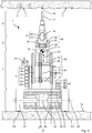
- the exemplary elevator 7 is based on a linear rail guide 38 .
- Two parallel rails 39 are mounted on the chassis 8 .
- the two profiled rails 39 define the lifting axis 25 .
- a runner 40 engages in the two profile rails 39 a.
- the rotor 40 is displaceable on the profile rails 39 along the lifting axis 25 .
- An electric motor 41 and a spindle 42 form the propulsion 24 for the rotor 40th
- the spindle 42 is rotatably supported between the two profile rails 39 .
- the rotor 40 has a spindle 42 engaging in the threaded 43rd
- the electric motor 41 rotates the spindle 42 about its longitudinal axis; the thread 43 converts the rotational movement into a movement along the lifting axis 25 .
- the exemplary elevator 7 in addition to the power lift 7 include a manually telekopierbare platform 44 .
- the platform 44 can be constructed comparatively compact.
- the power driven section can be brought to a basic height by means of the platform.
- the platform 44 may be single or multi-level.
- the example platform 44 is based on a rail guide.
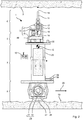
- An exemplary holder 5 has a trough-shaped shell 45 with a strap 46 .
- the handle 16 may be positioned in the shell 45 to be fixed with the tensioning belt 46 in the shell 45th With a second strap 47 , the housing of the power tool 6 can be lashed to the bracket 5 .
- the holder 5 is preferably displaceable perpendicular to the lifting axis 25 .
- the holder 5 can be displaceable, for example, on a dovetail guide 48 .
- the user can position the work axis 18 vertically to the wheel axle 28 .
- the bracket 5 may include an angular adjustment that allows for precise alignment of the working axis 18 parallel to the lifting axis 25 .
- the angle adjustment includes, for example, a joint and a set screw.
- the elevator 7 is preferably equipped with a sensor 49 for determining the contact pressure on the ceiling 3 .
- a sensor 49 for determining the contact pressure on the ceiling 3 .
- the holder 5 in the vertical direction 26 a spring 50 supported.
- the contact force presses the spring 50 together.
- a displacement sensor 51 for example a sliding potentiometer. determines the distance by which the spring 50 is compressed.
- With known spring constant of the sensor 49 determines the contact pressure.
- Other sensors for determining the contact force can be based on piezoelectric effects, stretch marks, etc.
- Other embodiments indirectly determine the contact pressure.
- the sensor 49 includes an evaluation of the power consumption, eg the current consumption, of the propulsion 24 .
- a correlation of the power consumption and a measure of the contact pressure are stored in a table in the sensor.
- the tool guide 1 may suspend dynamic balancing when the tool 11 contacts the blanket 3 . With the touch point on the ceiling 3 , the tool guide 1 can stand statically. The tool guide 1 can change to a stop mode S5 , in which the wheels 27 are blocked by a brake 53 ( Fig. 9 ). The balancing and the associated slight pendulum movement stops.
- the controller 9 immediately activates the balancing by means of the steering 20.
- the steering 20 aligns the elevator 7 vertically.
- the controller 9 may iteratively repeat the process described in the paragraph until the elevator 7 is vertically aligned. Subsequently, the controller 9 raises the elevator 7 at least preferably so far until a contact signal is applied.
- the tool guide 1 is now aligned vertically.
- the chassis 8 preferably has a brake 53.
- the brake 53 is preferably activated as soon as the tool guide 1 is aligned vertically and the contact signal is applied.
- the brake 53 is a parking brake which permanently blocks the wheels 27 of the chassis 8 .
- the brake 53 is realized for example as an engine brake.
- the brake 53 generates an electromagnetic force that counteracts movement of the wheels 27 .
- the brake 53 may be passive.
- the electric motors 29 can generate an electric current in the stator 31 according to a regenerative principle when their rotor 30 is rotated. Examples of the electric motors 29 with the generator principle are DC motors, universal motors, etc ..
- the regeneratively generated power is short-circuited by the brake 53 via a load resistor.
- the retroactive magnetic field counteracts the rotational movement of the rotor 30 .
- a speed sensor or motion sensor can detect movement.
- the steering 20 detects a corresponding control signal to counter-steer the propulsion 24 of the movement.
- the brake 53 can also be realized by a mechanical brake in the chassis 8 , for example a disc brake, drum brake.
- the mechanical brake 53 may assist the engine brake.
- the stationary battery 32 is electrically connected to the other batteries 55 .
- a charge controller 56 charges the stationary battery 32 with the other batteries 55 .
- Charge control 56 preferably maintains a charge level of stationary battery 32 above a distress level. The user can remove the other batteries 55 without danger.
- the stationary battery 32 has due to the emergency value sufficient charge level to balance the chassis 8 for at least 10 minutes, preferably at least half an hour.
- the tool guide 1 falls into an (emergency) mode S9 when the state of charge of the batteries 32, 55 drops below the emergency level.
- the emergency mode ensures a secure position of the tool guide 1 .
- the chassis 8 and the steering 20 are powered.
- the user can drive the tool guide 1 to a charging station or another desired location.
- Other consumers are preferably deactivated, in particular the elevator 7 and the power tool 6 are deactivated.
- the control console 22 may be disabled for user input. The user can no longer lift the control station 22 .
- the hand tool 6 can be separated from the batteries by means of a switch.
- the elevator 7 can be retracted automatically in the emergency mode to the lowest height.
- the tool guide 1 can indicate the emergency mode visually or acoustically in the emergency mode.
Priority Applications (3)
| Application Number | Priority Date | Filing Date | Title |
|---|---|---|---|
| EP17203220.3A EP3488976A1 (fr) | 2017-11-23 | 2017-11-23 | Guide d'outil à alignement automatique |
| EP18789776.4A EP3713715B1 (fr) | 2017-11-23 | 2018-10-31 | Guide d'outil à alignement automatique |
| PCT/EP2018/079801 WO2019101483A1 (fr) | 2017-11-23 | 2018-10-31 | Guide d'outil à autoalignement |
Applications Claiming Priority (1)
| Application Number | Priority Date | Filing Date | Title |
|---|---|---|---|
| EP17203220.3A EP3488976A1 (fr) | 2017-11-23 | 2017-11-23 | Guide d'outil à alignement automatique |
Publications (1)
| Publication Number | Publication Date |
|---|---|
| EP3488976A1 true EP3488976A1 (fr) | 2019-05-29 |
Family
ID=60450552
Family Applications (2)
| Application Number | Title | Priority Date | Filing Date |
|---|---|---|---|
| EP17203220.3A Withdrawn EP3488976A1 (fr) | 2017-11-23 | 2017-11-23 | Guide d'outil à alignement automatique |
| EP18789776.4A Active EP3713715B1 (fr) | 2017-11-23 | 2018-10-31 | Guide d'outil à alignement automatique |
Family Applications After (1)
| Application Number | Title | Priority Date | Filing Date |
|---|---|---|---|
| EP18789776.4A Active EP3713715B1 (fr) | 2017-11-23 | 2018-10-31 | Guide d'outil à alignement automatique |
Country Status (2)
| Country | Link |
|---|---|
| EP (2) | EP3488976A1 (fr) |
| WO (1) | WO2019101483A1 (fr) |
Families Citing this family (1)
| Publication number | Priority date | Publication date | Assignee | Title |
|---|---|---|---|---|
| CN111251258B (zh) * | 2020-03-04 | 2023-02-17 | 浙江信普工贸有限公司 | 一种建筑电锤升降支架 |
Citations (10)
| Publication number | Priority date | Publication date | Assignee | Title |
|---|---|---|---|---|
| FR2446155A1 (fr) * | 1979-01-09 | 1980-08-08 | Villedary Jacques | Support mobile pour outil pneumatique tel que marteau piqueur |
| DE3328582A1 (de) | 1982-09-27 | 1984-03-29 | Siemens AG, 1000 Berlin und 8000 München | Fahrbares deckenbohr- und montagegeraet fuer schlagduebel |
| DE29709281U1 (de) * | 1996-05-03 | 1997-11-20 | Lindner Ag | Vorrichtung zum Anbringen von Aufhängeelementen |
| US5794721A (en) * | 1996-09-06 | 1998-08-18 | Long-Airdox Company | Drilling apparatus |
| US20040007425A1 (en) * | 1994-05-27 | 2004-01-15 | Kamen Dean L. | Self-balancing ladder and camera dolly |
| US20080147281A1 (en) * | 2006-11-15 | 2008-06-19 | Shinji Ishii | Travel device |
| DE102007000253A1 (de) * | 2007-05-03 | 2008-11-06 | Hilti Aktiengesellschaft | Transportabler teleskopierbarer Maschinenständer für eine Elektrohandwerkzeugmaschine |
| US20090055033A1 (en) * | 2007-08-23 | 2009-02-26 | Segway Inc. | Apparatus and methods for fault detection at vehicle startup |
| US20100174476A1 (en) * | 2007-04-25 | 2010-07-08 | Toshio Fuwa | Inverted wheel type moving body and method of controlling the same |
| CA2841506A1 (fr) * | 2014-02-04 | 2015-08-04 | Brandt Engineered Products Ltd. | Machine et appareil de boulonnage |
-
2017
- 2017-11-23 EP EP17203220.3A patent/EP3488976A1/fr not_active Withdrawn
-
2018
- 2018-10-31 EP EP18789776.4A patent/EP3713715B1/fr active Active
- 2018-10-31 WO PCT/EP2018/079801 patent/WO2019101483A1/fr unknown
Patent Citations (10)
| Publication number | Priority date | Publication date | Assignee | Title |
|---|---|---|---|---|
| FR2446155A1 (fr) * | 1979-01-09 | 1980-08-08 | Villedary Jacques | Support mobile pour outil pneumatique tel que marteau piqueur |
| DE3328582A1 (de) | 1982-09-27 | 1984-03-29 | Siemens AG, 1000 Berlin und 8000 München | Fahrbares deckenbohr- und montagegeraet fuer schlagduebel |
| US20040007425A1 (en) * | 1994-05-27 | 2004-01-15 | Kamen Dean L. | Self-balancing ladder and camera dolly |
| DE29709281U1 (de) * | 1996-05-03 | 1997-11-20 | Lindner Ag | Vorrichtung zum Anbringen von Aufhängeelementen |
| US5794721A (en) * | 1996-09-06 | 1998-08-18 | Long-Airdox Company | Drilling apparatus |
| US20080147281A1 (en) * | 2006-11-15 | 2008-06-19 | Shinji Ishii | Travel device |
| US20100174476A1 (en) * | 2007-04-25 | 2010-07-08 | Toshio Fuwa | Inverted wheel type moving body and method of controlling the same |
| DE102007000253A1 (de) * | 2007-05-03 | 2008-11-06 | Hilti Aktiengesellschaft | Transportabler teleskopierbarer Maschinenständer für eine Elektrohandwerkzeugmaschine |
| US20090055033A1 (en) * | 2007-08-23 | 2009-02-26 | Segway Inc. | Apparatus and methods for fault detection at vehicle startup |
| CA2841506A1 (fr) * | 2014-02-04 | 2015-08-04 | Brandt Engineered Products Ltd. | Machine et appareil de boulonnage |
Non-Patent Citations (1)
| Title |
|---|
| SEGWAY INC.: "User Manual - Segway Personal Transporter", 31 December 2014 (2014-12-31), pages 57,59, XP002780951, Retrieved from the Internet <URL:http://www.segway.com/media/1195/24010-00001_aa_se_um_en_usb_user-manual.pdf> [retrieved on 20180511] * |
Also Published As
| Publication number | Publication date |
|---|---|
| EP3713715A1 (fr) | 2020-09-30 |
| WO2019101483A1 (fr) | 2019-05-31 |
| EP3713715B1 (fr) | 2023-07-26 |
Similar Documents
| Publication | Publication Date | Title |
|---|---|---|
| WO2019101478A1 (fr) | Guide d'outil à autoalignement | |
| EP3947019B1 (fr) | Guidage d'outil auto-aligneur | |
| WO2019101481A1 (fr) | Guide d'outil à autoalignement | |
| EP3713718B1 (fr) | Guide d'outil à alignement automatique | |
| US10988191B2 (en) | Load transporting apparatus and methods of using same | |
| US20220379457A1 (en) | Improved Self-Balancing Tool Guide | |
| EP3713715B1 (fr) | Guide d'outil à alignement automatique | |
| WO2019101482A1 (fr) | Guide d'outil à autoalignement | |
| AT507338B1 (de) | Fahrbarer bohrlochpositionierer, insbesondere selbstfahrender, automatischer bohrroboter | |
| DE102020207437A1 (de) | Vorrichtung zur Gleisbearbeitung | |
| CN211573385U (zh) | Agv智能钻孔小车 | |
| DE19811220A1 (de) | Manipulator, insbesondere Spielzeugmanipulator und Verfahren zur Positionierung, Montage und/oder Demontage von Bausteinen mit einem Manipulator, insbesondere einem Spielzeugmanipulator | |
| CN110984855A (zh) | Agv智能钻孔小车及其对建筑物的钻孔方法 | |
| CN115717467A (zh) | 吊杆安装设备 | |
| CN108213516A (zh) | 一种汽车壳体定位打孔设备 | |
| DE19726613A1 (de) | Selbstfahrbare Werkzeugmaschine |
Legal Events
| Date | Code | Title | Description |
|---|---|---|---|
| PUAI | Public reference made under article 153(3) epc to a published international application that has entered the european phase |
Free format text: ORIGINAL CODE: 0009012 |
|
| AK | Designated contracting states |
Kind code of ref document: A1 Designated state(s): AL AT BE BG CH CY CZ DE DK EE ES FI FR GB GR HR HU IE IS IT LI LT LU LV MC MK MT NL NO PL PT RO RS SE SI SK SM TR |
|
| AX | Request for extension of the european patent |
Extension state: BA ME |
|
| STAA | Information on the status of an ep patent application or granted ep patent |
Free format text: STATUS: THE APPLICATION IS DEEMED TO BE WITHDRAWN |
|
| 18D | Application deemed to be withdrawn |
Effective date: 20191130 |