EP3488945A1 - Mold forming method - Google Patents
Mold forming method Download PDFInfo
- Publication number
- EP3488945A1 EP3488945A1 EP17830645.2A EP17830645A EP3488945A1 EP 3488945 A1 EP3488945 A1 EP 3488945A1 EP 17830645 A EP17830645 A EP 17830645A EP 3488945 A1 EP3488945 A1 EP 3488945A1
- Authority
- EP
- European Patent Office
- Prior art keywords
- squeeze
- pattern
- molding
- flask
- molding sand
- Prior art date
- Legal status (The legal status is an assumption and is not a legal conclusion. Google has not performed a legal analysis and makes no representation as to the accuracy of the status listed.)
- Granted
Links
Images


Classifications
-
- B—PERFORMING OPERATIONS; TRANSPORTING
- B22—CASTING; POWDER METALLURGY
- B22C—FOUNDRY MOULDING
- B22C15/00—Moulding machines characterised by the compacting mechanism; Accessories therefor
- B22C15/28—Compacting by different means acting simultaneously or successively, e.g. preliminary blowing and finally pressing
- B22C15/30—Compacting by different means acting simultaneously or successively, e.g. preliminary blowing and finally pressing by both pressing and jarring devices
-
- B—PERFORMING OPERATIONS; TRANSPORTING
- B22—CASTING; POWDER METALLURGY
- B22C—FOUNDRY MOULDING
- B22C15/00—Moulding machines characterised by the compacting mechanism; Accessories therefor
- B22C15/02—Compacting by pressing devices only
-
- B—PERFORMING OPERATIONS; TRANSPORTING
- B22—CASTING; POWDER METALLURGY
- B22C—FOUNDRY MOULDING
- B22C11/00—Moulding machines characterised by the relative arrangement of the parts of same
-
- B—PERFORMING OPERATIONS; TRANSPORTING
- B22—CASTING; POWDER METALLURGY
- B22C—FOUNDRY MOULDING
- B22C11/00—Moulding machines characterised by the relative arrangement of the parts of same
- B22C11/02—Machines in which the moulds are moved during a cycle of successive operations
- B22C11/08—Machines in which the moulds are moved during a cycle of successive operations by non-rotary conveying means, e.g. by travelling platforms
-
- B—PERFORMING OPERATIONS; TRANSPORTING
- B22—CASTING; POWDER METALLURGY
- B22C—FOUNDRY MOULDING
- B22C11/00—Moulding machines characterised by the relative arrangement of the parts of same
- B22C11/10—Moulding machines characterised by the relative arrangement of the parts of same with one or more flasks forming part of the machine, from which only the sand moulds made by compacting are removed
-
- B—PERFORMING OPERATIONS; TRANSPORTING
- B22—CASTING; POWDER METALLURGY
- B22C—FOUNDRY MOULDING
- B22C15/00—Moulding machines characterised by the compacting mechanism; Accessories therefor
- B22C15/23—Compacting by gas pressure or vacuum
- B22C15/24—Compacting by gas pressure or vacuum involving blowing devices in which the mould material is supplied in the form of loose particles
-
- B—PERFORMING OPERATIONS; TRANSPORTING
- B22—CASTING; POWDER METALLURGY
- B22C—FOUNDRY MOULDING
- B22C9/00—Moulds or cores; Moulding processes
- B22C9/02—Sand moulds or like moulds for shaped castings
Definitions
- the present invention relates to a method for molding by squeezing molding sand that has filled flasks.
- a molding space is formed as follows: in the portion of a pattern, which portion is high, squeeze feet are lowered to reduce the amount of the molding sand, and in the portion of a pattern, which portion is low, the squeeze feet remain to be lifted so that the amount of the molding sand to be squeezed is large.
- This process has been publicly known (for example, see Patent Literature 1).
- the present invention has been conceived to solve that problem. Its aim is to provide a method for molding by which the density of the sand in a mold at the portion of a pattern that is concave on the parting plane is caused to be high, so that the density of the sand in the mold is almost uniform.
- Patent Literature 1 Japanese Patent Application Publication No. 2001-38451
- a method for molding of the present invention is to form a mold by using molding sand wherein a flask and a pattern plate are used. It has a step of forming a molding space by using the flask, using an auxiliary flask that has a lower opening that is connectable to an upper opening of the flask, using a squeeze head that has a squeeze board that can enter and withdraw from the auxiliary flask and has a plurality of squeeze feet that pass through the squeeze board and vertically move in relation to the squeeze board, and using the pattern plate. It also has a step of filling the molding sand into the molding space, which molding sand has been stored in a hopper for filling the molding sand.
- It also has a step of squeezing the molding sand by lowering the squeeze head.
- the squeeze feet that face a concavity of a pattern that is formed in the pattern plate are lowered at the same time as the step of squeezing starts, or during the step of squeezing.
- a pressure for squeezing that is a pressure to squeeze the molding sand is measured. If the measured pressure for squeezing reaches a predetermined pressure, the squeeze feet that face the concavity of the pattern that is formed in the pattern plate start to be lowered.
- a downward distance of the squeeze head to squeeze the molding sand is measured. If the measured downward distance reaches a predetermined distance, the squeeze feet that face a concavity of the pattern that is formed in the pattern plate start to be lowered.
- the squeeze feet that face the convexity of the pattern that is formed in the pattern plate are lowered, and then the step of filling is carried out.
- the step of squeezing is carried out after the squeeze feet that face the convexity of the pattern that is formed in the pattern plate are lifted or while the squeeze feet are being lifted.
- a frame that encloses, and vertically slides on, the outer circumference of the pattern plate, is used.
- the molding space is partially formed by means of the frame.
- the method for molding is to form a mold by molding sand wherein a flask and a pattern plate are used, the method comprising the steps of 1) forming a molding space by using the flask, an auxiliary flask that has a lower opening that is connectable to an upper opening of the flask, a squeeze head that has a squeeze board that can enter and withdraw from the auxiliary flask and a plurality of squeeze feet that pass through the squeeze board and vertically move in relation to the squeeze board, and the pattern plate, 2) filling the molding sand that has been stored in a hopper for filling the molding sand into the molding space, and 3) squeezing the molding sand by lowering the squeeze head, wherein the squeeze feet that face a concavity of a pattern that is formed in the pattern plate are lowered at the same time as the step of squeezing starts or during the step of squeezing, various advantages can be achieved, such that the density of the sand in the mold
- Fig. 1 is a schematic sectional view of the embodiment to show a portion for filling the molding sand and a portion for squeezing the molding sand of the molding machine.
- the portions of the molding machine other than the portion for filling the molding sand and the portion for squeezing the molding sand of the molding machine are omitted.
- a pattern plate 2 for the upper flask is detachably attached to a carrier 1 for the pattern.
- the outer circumference of the pattern plate 2 is surrounded by the carrier 1 for the pattern.
- the flask 3 is mounted on the carrier 1 for the pattern (the pattern plate 2).
- the flask 3 is conveyed into and out of the molding machine by a conveyor for carrying the flask in and out, which is not shown.
- the flask 3 is vertically moved by a means for vertically moving the flask, which is also not shown.
- auxiliary flask 4 adheres to the flask 3 under a pushing force.
- the auxiliary flask 4 has a lower opening 4a that is connectable to an upper opening 3a of the flask 3.
- the auxiliary flask 4 is vertically moved by a means for vertically moving an auxiliary flask, which is not shown.
- the auxiliary flask 4 is equipped with an encoder, which is not shown, so that the vertical distance of the auxiliary flask 4 is measured by the encoder.
- Fig. 1 shows the status in which the upper opening 3a of the flask 3 is connected to the lower opening 4a of the auxiliary flask 4.
- the lower end of the hopper 5 for filling the molding sand that stores the molding sand S (green sand in this embodiment) is inserted into the auxiliary flask 4.
- a squeeze head 6 is attached to the lower end of the hopper 5 for filling the molding sand to be inserted into the auxiliary flask 4.
- the squeeze head 6 has a squeeze board 7 that vertically moves within the auxiliary flask 4 and has a plurality of segment-type squeeze feet 8 that pass through the squeeze board 7 and that vertically move in relation to the squeeze board 7.
- the plurality of squeeze feet 8 are driven by an oil cylinder.
- a port 10 for supplying the molding sand is formed at the top of the hopper 5 for filling the molding sand.
- the port 10 is closed by a sliding gate 9.
- a pipe 12 for supplying air which introduces air at a low pressure (e.g., 0.05 - 0.18 MPa), is connected to the upper portion of the hopper 5 for filling the molding sand through an on-off valve 11.
- the lower portion of the hopper 5 for filling the molding sand is formed by a bifurcated bifurcating chute 13.
- On the inner surface of the hopper 5 for filling the molding sand many apertures 14 for ejecting air are provided that connect to a source of compressed air, which is not shown, through an on-off valve, which is not shown.
- Air at a low pressure (e.g., 0.05 - 0.18 MPa) is ejected from the many apertures 14 for ejecting air into the hopper 5 for filling the molding sand to form the aeration by which the molding sand S is floated and fluidized.
- a port 15 for filling the molding sand is provided to downwardly feed the molding sand S in the chute 13.
- Nozzles 16 for filling the molding sand are formed at both sides of the squeeze feet 8 of the squeeze board 7 so as to feed the molding sand S to a molding space below the squeeze board 7.
- the nozzles 16 for filling the molding sand are connected to the respective ports 15 for filling the molding sand.
- the hopper 5 for filling the molding sand and the squeeze head 6, which is attached to the bottom of the hopper 5, are vertically moved by means for vertically moving the hopper for filling the molding sand (an oil cylinder in this embodiment), which is not shown.
- a convexity 2a of the pattern and a concavity 2b of the pattern are formed in the pattern plate 2.
- the convexity of the pattern is the part of the pattern that is higher than the level of the parting plane 2c of the pattern plate 2.
- the concavity of the pattern is the part of the pattern that is lower than the level of the parting plane 2c of the pattern plate 2.
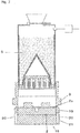
- Fig. 1 shows a state where a molding space is formed by means of the flask 3, the auxiliary flask 4, the squeeze head 6, and the pattern plate 2.
- the squeeze feet 8 that face the convexity 2a of the pattern formed in the pattern plate 2 are lowered to a predetermined position, to be in a state as in Fig. 2 .
- the amount of the molding sand S that is to be squeezed by the squeeze feet 8 that face the convexity 2a of the pattern is reduced.
- a preferable molding space is formed.
- air at a low pressure is ejected through the many apertures 14 for ejecting air to the hopper 5 for filling the molding sand.
- the aeration is carried out where the molding sand S in the hopper 5 for filling the molding sand is floated and fluidized. While the aeration is carried out, air at the low pressure is supplied from the pipe 12 for supplying air to the hopper 5 for filling the molding sand through the on-off valve 11.
- the molding sand S is filled by the aeration by means of the air at the low pressure in the molding space through the port 15 for filling the molding sand and the nozzle 16 for filling the molding sand, as in Fig. 3 .
- the air that is used for filling by the aeration is discharged through vent holes in the auxiliary flask 4, which vent holes are not shown.
- the squeeze feet 8 that face the convexity 2a of the pattern are lifted to the upper end.
- a vacant portion 17 which is a space where there is no molding sand S, is formed in the molding space.
- the hopper 5 for filling the molding sand and the squeeze head 6 are lowered by a means for vertically moving the hopper for filling the molding sand so that the molding sand S in the molding space is squeezed by means of the squeeze board 7 and the plurality of the squeeze feet 8.
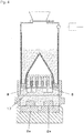
- the squeeze feet 8 that face the concavity 2b of the pattern that is formed in the pattern plate 2 are lowered, so that the molding sand S in the concavity 2b of the pattern is partially squeezed (see Fig. 5 ).
- the vacant portion 17 disappears as the squeeze feet 8 are lowered to squeeze.
- the hopper 5 for filling the molding sand and the squeeze head 6 are lifted by the means for vertically moving the hopper for filling the molding sand, so that the squeeze head 6 is separated from the flask 3 in which the mold is molded.
- the squeeze feet 8 that face the concavity 2b of the pattern are lifted as high as possible.
- the auxiliary flask 4 is lifted by the means for vertically moving the auxiliary flask, so that the auxiliary flask 4 is separated from the flask 3.
- the flask is lifted by the means for vertically moving the flask, so that the mold is drawn out of the flask.
- the flask 3 is separated from the pattern plate 2.
- the flask 3 in which the mold is molded is carried out by means of the conveyor for carrying the flask in and out. Then an empty flask 3 is conveyed.
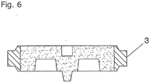
- the flask 3 in which the mold has been molded is shown in Fig. 6 .
- the pattern plate 2 and the carrier 1 for the pattern are carried out of the molding machine by means of a device for changing a pattern, which is not shown.
- a pattern plate for a lower flask, which is not shown, and the pattern carrier, are carried in the molding machine.
- the empty flask 3 is lowered by the means for vertically moving the flask to be placed on a pattern plate (a pattern carrier) for a lower flask.
- the auxiliary flask 4 is lowered by the means for vertically moving the auxiliary flask, to adhere to the flask 3 under a pushing force.
- the hopper 5 for filling the molding sand and the squeeze head 6 are lowered by the means for vertically moving the hopper for filling the molding sand, so that the squeeze head 6 is inserted into the auxiliary flask 4. In this way the molding space is again formed. The above-mentioned operation is repeated.
- the pressure to lower the squeeze feet 8 that face the concavity 2b of the pattern that is formed in the pattern plate 2 can be changed to a desired pressure, namely, it is adjustable.
- a desired pressure namely, it is adjustable.
- the pressure to lower these squeeze feet 8 is set to be a pressure that is lower than the designed pressure (for example, one-half of the designed pressure), so that the resistance in removing the concavity 2b of the pattern from the mold in a vertical direction is reduced.
- the designed pressure for example, one-half of the designed pressure
- the pressure for squeezing the molding sand S by lowering the squeeze head 6 is measured. If the measured pressure reaches the set pressure, the squeeze feet 8 that face the concavity 2b of the pattern that is formed in the pattern plate 2 start to be lowered.
- the molding sand S may not be sufficiently squeezed, depending on the shape of the pattern. If it were to be too late, the molding sand S would not have been squeezed by lowering the squeeze feet 8, since to some extent it had already been squeezed.
- the squeeze feet 8 that face the concavity 2b of the pattern can start to be lowered at an appropriate time. This is an advantage.
- the pressure for squeezing the molding sand S by lowering the squeeze head 6 acts as a pressure to lower the means for vertically moving the hopper for filling the molding sand in order to squeeze the molding sand S.
- the time for starting to lower the squeeze feet 8 that face the concavity 2b of the pattern is determined as above.
- the configuration is not limited to this one.
- the downward distance of the squeeze head 6 to squeeze the molding sand S is measured.
- the squeeze feet 8 that face the concavity 2b of the pattern that is formed in the pattern plate 2 may start to be lowered.
- an encoder which is not shown, is attached to the hopper 5 for filling the molding sand to measure the downward distance of the squeeze head 6.
- the squeeze feet 8 that face the convexity 2a of the pattern that is formed in the pattern plate 2 are lowered, and then the molding sand S fills the molding space.
- this step need not be carried out. Namely, it is not mandatory.
- the squeeze feet 8 that face the convexity 2a of the pattern are not lowered, no step of lifting them is carried out.
- the squeeze feet 8 that face the convexity 2a of the pattern that is formed in the pattern plate 2 is lifted, and then the squeeze head 6 is lowered to squeeze the molding sand S.
- a vacant portion 17 that is a part of the molding space where there is no molding sand S can be formed as in Fig. 4 .
- the amount of the molding sand S that is to be squeezed on the convexity 2a of the pattern is reduced.
- the squeeze feet 8 that face the concavity 2b of the pattern are lowered, the molding sand S on the concavity 2b of the pattern is easily squeezed. This is an advantage.
- the squeeze head 6 is lowered to squeeze the molding sand S.
- the configuration is not limited to this one.
- the squeeze head 6 may be lowered to squeeze the molding sand S.
- the carrier 1 for the pattern is not limited to the above-mentioned one. Now another embodiment of the carrier for the pattern is discussed.
- Fig. 7 shows that a molding space is formed by using another carrier 18 for the pattern.
- the carrier 18 for the pattern has a frame 19 that surrounds the outer circumference of the pattern plate 2 and vertically slides on it.
- Multiple guiding pins 20 are connected to the bottom of the frame 19.
- the guiding pins 20 are vertically and slidably inserted into the main frame 21.
- the frame 19 is vertically moved through the guiding pin 20 by means of a vertical cylinder, which is not shown.
- the upper surface of the frame 19 slightly projects (e.g., 30 mm) from the parting plane 2c of the pattern plate 2 when the vertical cylinder is extended to its maximum (see Fig. 7 ).
- the upper surface of the frame 19 is almost on the same plane as the parting plane 2c of the pattern plate 2 when the vertical cylinder is retracted.
- the carrier 18 for the pattern has the frame 19 that surrounds the outer circumference of the pattern plate 2 and vertically slides on it.
- the molding space is partially formed by the frame 19.
- the nozzles 16 for filling the molding sand are formed at both sides of the plurality of the squeeze feet 8 of the squeeze board 7.
- the configuration is not limited to this one.
- the nozzles 16 for filling the molding sand may be formed to pass though the sides of the auxiliary flask 4.
- the bifurcated chute 13, which is the lower part of the hopper 5 for filling the molding sand may be located outside of the auxiliary flask 4 and may be fixed to it.
- the port 15 for filling the molding sand that is provided at the bottom of the chute 13 can be connected to the nozzle 16 for filling the molding sand that is formed in the side of the auxiliary flask 4.
- the squeeze head 6 can be vertically moved by means of another actuator.
Abstract
Description
- The present invention relates to a method for molding by squeezing molding sand that has filled flasks.
- Conventionally, to make uniform the density of the sand in a mold, a molding space is formed as follows: in the portion of a pattern, which portion is high, squeeze feet are lowered to reduce the amount of the molding sand, and in the portion of a pattern, which portion is low, the squeeze feet remain to be lifted so that the amount of the molding sand to be squeezed is large. This process has been publicly known (for example, see Patent Literature 1).
- However, a problem has existed in that though the above process is effective for a pattern that has a convex shape on the parting plane it is less effective for a pattern that has a concave shape, such as a shape like a pocket, on the parting plane.
- The present invention has been conceived to solve that problem. Its aim is to provide a method for molding by which the density of the sand in a mold at the portion of a pattern that is concave on the parting plane is caused to be high, so that the density of the sand in the mold is almost uniform.
- [Patent Literature 1]
Japanese Patent Application Publication No.2001-38451 - To achieve the above-mentioned aim, a method for molding of the present invention is to form a mold by using molding sand wherein a flask and a pattern plate are used. It has a step of forming a molding space by using the flask, using an auxiliary flask that has a lower opening that is connectable to an upper opening of the flask, using a squeeze head that has a squeeze board that can enter and withdraw from the auxiliary flask and has a plurality of squeeze feet that pass through the squeeze board and vertically move in relation to the squeeze board, and using the pattern plate. It also has a step of filling the molding sand into the molding space, which molding sand has been stored in a hopper for filling the molding sand. It also has a step of squeezing the molding sand by lowering the squeeze head. The squeeze feet that face a concavity of a pattern that is formed in the pattern plate are lowered at the same time as the step of squeezing starts, or during the step of squeezing.
- By the method for molding of the present invention a pressure to lower the squeeze feet that face the concavity of the pattern that is formed in the pattern plate is adjusted.
- By the method for molding of the present invention, in the step of squeezing, a pressure for squeezing that is a pressure to squeeze the molding sand is measured. If the measured pressure for squeezing reaches a predetermined pressure, the squeeze feet that face the concavity of the pattern that is formed in the pattern plate start to be lowered.
- By the method for molding of the present invention, in the step of squeezing, a downward distance of the squeeze head to squeeze the molding sand is measured. If the measured downward distance reaches a predetermined distance, the squeeze feet that face a concavity of the pattern that is formed in the pattern plate start to be lowered.
- By the method for molding of the present invention, in the step of forming the molding space, the squeeze feet that face the convexity of the pattern that is formed in the pattern plate are lowered, and then the step of filling is carried out.
- By the method for molding of the present invention, after the step of filling, the step of squeezing is carried out after the squeeze feet that face the convexity of the pattern that is formed in the pattern plate are lifted or while the squeeze feet are being lifted.
- By the method for molding of the present invention a frame that encloses, and vertically slides on, the outer circumference of the pattern plate, is used. The molding space is partially formed by means of the frame.
- By the present invention, since the method for molding is to form a mold by molding sand wherein a flask and a pattern plate are used, the method comprising the steps of 1) forming a molding space by using the flask, an auxiliary flask that has a lower opening that is connectable to an upper opening of the flask, a squeeze head that has a squeeze board that can enter and withdraw from the auxiliary flask and a plurality of squeeze feet that pass through the squeeze board and vertically move in relation to the squeeze board, and the pattern plate, 2) filling the molding sand that has been stored in a hopper for filling the molding sand into the molding space, and 3) squeezing the molding sand by lowering the squeeze head, wherein the squeeze feet that face a concavity of a pattern that is formed in the pattern plate are lowered at the same time as the step of squeezing starts or during the step of squeezing, various advantages can be achieved, such that the density of the sand in the mold can be increased at a portion where the pattern is concave in relation to the parting plane so that the density of the sand in the mold can be made uniform.
- The basic Japanese patent application, No.
2016-142452, filed July 20, 2016 - The present invention will become more fully understood from the detailed description given below. However, that description and the specific embodiments are only illustrations of the desired embodiments of the present invention, and so are given only for an explanation. Various possible changes and modifications will be apparent to those of ordinary skill in the art on the basis of the detailed description.
- The applicant has no intention to dedicate to the public any disclosed embodiment. Among the disclosed changes and modifications, those which may not literally fall within the scope of the present claims constitute, therefore, under the doctrine of equivalents, a part of the present invention.
- The use of the articles "a," "an," and "the" and similar referents in the specification and claims are to be construed to cover both the singular and the plural form of a noun, unless otherwise indicated herein or clearly contradicted by the context. The use of any and all examples, or exemplary language (e.g., "such as") provided herein is intended merely to better illuminate the invention, and so does not limit the scope of the invention, unless otherwise stated.
-
-
Fig. 1 is a schematic sectional view of the configuration of the embodiment of the present invention when a molding space is formed. -
Fig. 2 is a schematic sectional view of the configuration of the embodiment of the present invention when the squeeze feet that face a convexity of the pattern are lowered to a predetermined position. -
Fig. 3 is a schematic sectional view of the configuration of the embodiment of the present invention when the molding sand is subject to aeration. -
Fig. 4 is a schematic sectional view of the configuration of the embodiment of the present invention when the squeeze feet that face the convexity of the pattern are lifted to an upper end. -
Fig. 5 is a schematic sectional view of the configuration of the embodiment of the present invention when squeezing the molding sand is completed. -
Fig. 6 is a sectional view of a flask in which a mold is formed. -
Fig. 7 is a schematic sectional view of the configuration of the embodiment of the present invention when a molding space is formed by using another pattern carrier. - Below, an embodiment of the present invention is discussed with reference to the drawings. The embodiment uses a tight flask molding machine as a molding machine, by which an upper mold and a lower mold are alternately molded in an upper flask and a lower flask, respectively.
Fig. 1 is a schematic sectional view of the embodiment to show a portion for filling the molding sand and a portion for squeezing the molding sand of the molding machine. Thus the portions of the molding machine other than the portion for filling the molding sand and the portion for squeezing the molding sand of the molding machine are omitted. - As in
Fig. 1 , apattern plate 2 for the upper flask is detachably attached to acarrier 1 for the pattern. The outer circumference of thepattern plate 2 is surrounded by thecarrier 1 for the pattern. Theflask 3 is mounted on thecarrier 1 for the pattern (the pattern plate 2). Theflask 3 is conveyed into and out of the molding machine by a conveyor for carrying the flask in and out, which is not shown. Theflask 3 is vertically moved by a means for vertically moving the flask, which is also not shown. - An
auxiliary flask 4 adheres to theflask 3 under a pushing force. Theauxiliary flask 4 has alower opening 4a that is connectable to an upper opening 3a of theflask 3. Theauxiliary flask 4 is vertically moved by a means for vertically moving an auxiliary flask, which is not shown. Theauxiliary flask 4 is equipped with an encoder, which is not shown, so that the vertical distance of theauxiliary flask 4 is measured by the encoder.Fig. 1 shows the status in which the upper opening 3a of theflask 3 is connected to thelower opening 4a of theauxiliary flask 4. - The lower end of the
hopper 5 for filling the molding sand that stores the molding sand S (green sand in this embodiment) is inserted into theauxiliary flask 4. Asqueeze head 6 is attached to the lower end of thehopper 5 for filling the molding sand to be inserted into theauxiliary flask 4. Thesqueeze head 6 has asqueeze board 7 that vertically moves within theauxiliary flask 4 and has a plurality of segment-type squeeze feet 8 that pass through thesqueeze board 7 and that vertically move in relation to thesqueeze board 7. In this embodiment the plurality ofsqueeze feet 8 are driven by an oil cylinder. - A
port 10 for supplying the molding sand is formed at the top of thehopper 5 for filling the molding sand. Theport 10 is closed by asliding gate 9. Apipe 12 for supplying air, which introduces air at a low pressure (e.g., 0.05 - 0.18 MPa), is connected to the upper portion of thehopper 5 for filling the molding sand through an on-offvalve 11. The lower portion of thehopper 5 for filling the molding sand is formed by a bifurcated bifurcatingchute 13. On the inner surface of thehopper 5 for filling the molding sandmany apertures 14 for ejecting air are provided that connect to a source of compressed air, which is not shown, through an on-off valve, which is not shown. - Air at a low pressure (e.g., 0.05 - 0.18 MPa) is ejected from the
many apertures 14 for ejecting air into thehopper 5 for filling the molding sand to form the aeration by which the molding sand S is floated and fluidized. At the bottom of thechute 13 of thehopper 5 for filling the molding sand aport 15 for filling the molding sand is provided to downwardly feed the molding sand S in thechute 13. -
Nozzles 16 for filling the molding sand are formed at both sides of thesqueeze feet 8 of thesqueeze board 7 so as to feed the molding sand S to a molding space below thesqueeze board 7. Thenozzles 16 for filling the molding sand are connected to therespective ports 15 for filling the molding sand. Thehopper 5 for filling the molding sand and thesqueeze head 6, which is attached to the bottom of thehopper 5, are vertically moved by means for vertically moving the hopper for filling the molding sand (an oil cylinder in this embodiment), which is not shown. - A
convexity 2a of the pattern and aconcavity 2b of the pattern are formed in thepattern plate 2. Here, the convexity of the pattern is the part of the pattern that is higher than the level of theparting plane 2c of thepattern plate 2. The concavity of the pattern is the part of the pattern that is lower than the level of theparting plane 2c of thepattern plate 2. - The operation of the device as configured above is now discussed.
Fig. 1 shows a state where a molding space is formed by means of theflask 3, theauxiliary flask 4, thesqueeze head 6, and thepattern plate 2. Next, thesqueeze feet 8 that face theconvexity 2a of the pattern formed in thepattern plate 2 are lowered to a predetermined position, to be in a state as inFig. 2 . Thus the amount of the molding sand S that is to be squeezed by thesqueeze feet 8 that face theconvexity 2a of the pattern is reduced. Thus a preferable molding space is formed. - Next, air at a low pressure is ejected through the
many apertures 14 for ejecting air to thehopper 5 for filling the molding sand. The aeration is carried out where the molding sand S in thehopper 5 for filling the molding sand is floated and fluidized. While the aeration is carried out, air at the low pressure is supplied from thepipe 12 for supplying air to thehopper 5 for filling the molding sand through the on-offvalve 11. The molding sand S is filled by the aeration by means of the air at the low pressure in the molding space through theport 15 for filling the molding sand and thenozzle 16 for filling the molding sand, as inFig. 3 . During this period the air that is used for filling by the aeration is discharged through vent holes in theauxiliary flask 4, which vent holes are not shown. - Next, the
squeeze feet 8 that face theconvexity 2a of the pattern are lifted to the upper end. As inFig. 4 , avacant portion 17, which is a space where there is no molding sand S, is formed in the molding space. Next, thehopper 5 for filling the molding sand and thesqueeze head 6 are lowered by a means for vertically moving the hopper for filling the molding sand so that the molding sand S in the molding space is squeezed by means of thesqueeze board 7 and the plurality of thesqueeze feet 8. At the same time as the step of squeezing starts, or during the step of squeezing, thesqueeze feet 8 that face theconcavity 2b of the pattern that is formed in thepattern plate 2 are lowered, so that the molding sand S in theconcavity 2b of the pattern is partially squeezed (seeFig. 5 ). Thevacant portion 17 disappears as thesqueeze feet 8 are lowered to squeeze. - Next, the
hopper 5 for filling the molding sand and thesqueeze head 6 are lifted by the means for vertically moving the hopper for filling the molding sand, so that thesqueeze head 6 is separated from theflask 3 in which the mold is molded. Thesqueeze feet 8 that face theconcavity 2b of the pattern are lifted as high as possible. Theauxiliary flask 4 is lifted by the means for vertically moving the auxiliary flask, so that theauxiliary flask 4 is separated from theflask 3. Next, the flask is lifted by the means for vertically moving the flask, so that the mold is drawn out of the flask. Theflask 3 is separated from thepattern plate 2. - Next, the
flask 3 in which the mold is molded is carried out by means of the conveyor for carrying the flask in and out. Then anempty flask 3 is conveyed. Theflask 3 in which the mold has been molded is shown inFig. 6 . Next, thepattern plate 2 and thecarrier 1 for the pattern are carried out of the molding machine by means of a device for changing a pattern, which is not shown. A pattern plate for a lower flask, which is not shown, and the pattern carrier, are carried in the molding machine. - Next, the
empty flask 3 is lowered by the means for vertically moving the flask to be placed on a pattern plate (a pattern carrier) for a lower flask. Next, theauxiliary flask 4 is lowered by the means for vertically moving the auxiliary flask, to adhere to theflask 3 under a pushing force. Thehopper 5 for filling the molding sand and thesqueeze head 6 are lowered by the means for vertically moving the hopper for filling the molding sand, so that thesqueeze head 6 is inserted into theauxiliary flask 4. In this way the molding space is again formed. The above-mentioned operation is repeated. - In this embodiment, the pressure to lower the
squeeze feet 8 that face theconcavity 2b of the pattern that is formed in thepattern plate 2 can be changed to a desired pressure, namely, it is adjustable. By this configuration, the pressure to lower thesesqueeze feet 8 can be set to be low in comparison with the normal pressure, so that any defect can be prevented when theconcavity 2b of the pattern is removed. This is an advantage. - If the molding sand S near the
concavity 2b of the pattern were to be excessively squeezed and the resistance in removing theconcavity 2b of the pattern in a vertical direction (on the inner surface) were to greatly increase, a defect would occur when theconcavity 2b of the pattern is removed. To avoid this, the pressure to lower thesesqueeze feet 8 is set to be a pressure that is lower than the designed pressure (for example, one-half of the designed pressure), so that the resistance in removing theconcavity 2b of the pattern from the mold in a vertical direction is reduced. Thus a defect can be prevented from occurring when theconcavity 2b of the pattern is removed. - In this embodiment, the pressure for squeezing the molding sand S by lowering the
squeeze head 6 is measured. If the measured pressure reaches the set pressure, thesqueeze feet 8 that face theconcavity 2b of the pattern that is formed in thepattern plate 2 start to be lowered. - If the time for starting to lower the
squeeze feet 8 that face theconcavity 2b of the pattern were to be too early, the molding sand S may not be sufficiently squeezed, depending on the shape of the pattern. If it were to be too late, the molding sand S would not have been squeezed by lowering thesqueeze feet 8, since to some extent it had already been squeezed. By the configuration of the present invention, these problems can be overcome. Thesqueeze feet 8 that face theconcavity 2b of the pattern can start to be lowered at an appropriate time. This is an advantage. Incidentally, the pressure for squeezing the molding sand S by lowering thesqueeze head 6 acts as a pressure to lower the means for vertically moving the hopper for filling the molding sand in order to squeeze the molding sand S. - By this embodiment, the time for starting to lower the
squeeze feet 8 that face theconcavity 2b of the pattern is determined as above. However, the configuration is not limited to this one. For example, the downward distance of thesqueeze head 6 to squeeze the molding sand S is measured. When the measured distance reaches the designed distance, thesqueeze feet 8 that face theconcavity 2b of the pattern that is formed in thepattern plate 2 may start to be lowered. - By this above configuration the problems that are discussed above can be overcome, and the
squeeze feet 8 that face theconcavity 2b of the pattern can start to be lowered at an appropriate time. This is an advantage. In this embodiment, an encoder, which is not shown, is attached to thehopper 5 for filling the molding sand to measure the downward distance of thesqueeze head 6. - By this embodiment, when the molding space is formed, the
squeeze feet 8 that face theconvexity 2a of the pattern that is formed in thepattern plate 2 are lowered, and then the molding sand S fills the molding space. However, based on the shape of the pattern, this step need not be carried out. Namely, it is not mandatory. When thesqueeze feet 8 that face theconvexity 2a of the pattern are not lowered, no step of lifting them is carried out. - By this embodiment, after the molding sand S fills the molding space, the
squeeze feet 8 that face theconvexity 2a of the pattern that is formed in thepattern plate 2 is lifted, and then thesqueeze head 6 is lowered to squeeze the molding sand S. By this configuration, avacant portion 17 that is a part of the molding space where there is no molding sand S can be formed as inFig. 4 . The amount of the molding sand S that is to be squeezed on theconvexity 2a of the pattern is reduced. Thus, when thesqueeze feet 8 that face theconcavity 2b of the pattern are lowered, the molding sand S on theconcavity 2b of the pattern is easily squeezed. This is an advantage. - By this embodiment, after the
squeeze feet 8 that face theconvexity 2a of the pattern are lifted, thesqueeze head 6 is lowered to squeeze the molding sand S. However, the configuration is not limited to this one. For example, while thesqueeze feet 8 that face theconvexity 2a of the pattern are being lifted, thesqueeze head 6 may be lowered to squeeze the molding sand S. By this configuration a cycle time can be shortened. This is an advantage. - The
carrier 1 for the pattern is not limited to the above-mentioned one. Now another embodiment of the carrier for the pattern is discussed.Fig. 7 shows that a molding space is formed by using anothercarrier 18 for the pattern. Thecarrier 18 for the pattern has aframe 19 that surrounds the outer circumference of thepattern plate 2 and vertically slides on it. Multiple guiding pins 20 are connected to the bottom of theframe 19. The guiding pins 20 are vertically and slidably inserted into themain frame 21. Theframe 19 is vertically moved through the guidingpin 20 by means of a vertical cylinder, which is not shown. The upper surface of theframe 19 slightly projects (e.g., 30 mm) from theparting plane 2c of thepattern plate 2 when the vertical cylinder is extended to its maximum (seeFig. 7 ). The upper surface of theframe 19 is almost on the same plane as theparting plane 2c of thepattern plate 2 when the vertical cylinder is retracted. - In the embodiment, as in
Fig. 7 thecarrier 18 for the pattern has theframe 19 that surrounds the outer circumference of thepattern plate 2 and vertically slides on it. The molding space is partially formed by theframe 19. By this configuration, when the molding sand S in the molding space is squeezed, it is squeezed from the side by theframe 19 that is being lowered. This is an advantage. When theframe 19 is lifted, the mold that has been molded is lifted a little bit together with theflask 3. Thus the degree of the accuracy in removing the mold becomes high. This is an advantage. - By this embodiment, the
nozzles 16 for filling the molding sand are formed at both sides of the plurality of thesqueeze feet 8 of thesqueeze board 7. However, the configuration is not limited to this one. For example, thenozzles 16 for filling the molding sand may be formed to pass though the sides of theauxiliary flask 4. In this case, thebifurcated chute 13, which is the lower part of thehopper 5 for filling the molding sand, may be located outside of theauxiliary flask 4 and may be fixed to it. Theport 15 for filling the molding sand that is provided at the bottom of thechute 13 can be connected to thenozzle 16 for filling the molding sand that is formed in the side of theauxiliary flask 4. Thesqueeze head 6 can be vertically moved by means of another actuator. By this configuration, since nonozzle 16 for filling the molding sand is formed in thesqueeze board 7, thesqueeze feet 8 can be freely arranged in thesqueeze board 7. This is an advantage. - In this embodiment, if, when the squeezing operation is over the distance K1 from the bottom surface of the
squeeze board 7 to theparting plane 2c of thepattern plate 2 is close to the distance K2 from the bottom surface of thesqueeze feet 8 that face theconcavity 2b of the pattern to the bottom surface of theconcavity 2b of the pattern, the density of the molding sand in the mold becomes uniform. Thus this is preferable. - Below, the main reference numerals and symbols that are used in the detailed description and drawings are listed.
- 2 the pattern plate
- 2a the convexity of the pattern
- 2b the concavity of the pattern
- 3 the flasks
- 3a the upper opening
- 4 the auxiliary flask
- 4a the lower opening
- 5 the hopper for filling the molding sand
- 6 the squeeze head
- 7 the squeeze board
- 8 the squeeze feet
- 19 the frame
- S the molding sand
Claims (7)
- A method for molding by using molding sand wherein a flask and a pattern plate are used, the method comprising the steps of:forming a molding space by using the flask, using an auxiliary flask that has a lower opening that is connectable to an upper opening of the flask, using a squeeze head that has a squeeze board that can enter and withdraw from the auxiliary flask and has a plurality of squeeze feet that pass through the squeeze board and vertically move in relation to the squeeze board, and using the pattern plate;filling the molding sand into the molding space, which molding sand has been stored in a hopper for filling the molding sand; andsqueezing the molding sand by lowering the squeeze head;wherein the squeeze feet that face a concavity of a pattern that is formed in the pattern plate are lowered at the same time as the step of squeezing starts or during the step of squeezing.
- The method for molding of claim 1, wherein a pressure to lower the squeeze feet that face the concavity of the pattern that is formed in the pattern plate is adjusted.
- The method for molding of claim 1 or 2, wherein, in the step of squeezing, a pressure for squeezing that is a pressure to squeeze the molding sand is measured, and
wherein if the measured pressure for squeezing reaches a predetermined pressure, the squeeze feet that face the concavity of the pattern that is formed in the pattern plate start to be lowered. - The method for molding of claim 1 or 2, wherein, in the step of squeezing, a downward distance of the squeeze head to squeeze the molding sand is measured, and
wherein, if the measured downward distance reaches a predetermined distance, the squeeze feet that face a concavity of the pattern that is formed in the pattern plate start to be lowered. - The method for molding of claim 1 or 2, wherein, in the step of forming the molding space, the squeeze feet that face the convexity of the pattern that is formed in the pattern plate are lowered, and then the step of filling is carried out.
- The method for molding of claim 5, wherein after the step of filling, the step of squeezing is carried out after the squeeze feet that face the convexity of the pattern that is formed in the pattern plate are lifted or while the squeeze feet are being lifted.
- The method for molding of claim 1 or 2, wherein a frame that encloses, and vertically slides on, the outer circumference of the pattern plate, is used, and
wherein the molding space is partially formed by means of the frame.
Applications Claiming Priority (2)
| Application Number | Priority Date | Filing Date | Title |
|---|---|---|---|
| JP2016142452 | 2016-07-20 | ||
| PCT/JP2017/010595 WO2018016123A1 (en) | 2016-07-20 | 2017-03-16 | Mold forming method |
Publications (3)
| Publication Number | Publication Date |
|---|---|
| EP3488945A1 true EP3488945A1 (en) | 2019-05-29 |
| EP3488945A4 EP3488945A4 (en) | 2019-12-04 |
| EP3488945B1 EP3488945B1 (en) | 2020-08-19 |
Family
ID=60993294
Family Applications (1)
| Application Number | Title | Priority Date | Filing Date |
|---|---|---|---|
| EP17830645.2A Active EP3488945B1 (en) | 2016-07-20 | 2017-03-16 | Mold forming method |
Country Status (8)
| Country | Link |
|---|---|
| US (1) | US20190111474A1 (en) |
| EP (1) | EP3488945B1 (en) |
| JP (1) | JP6665935B2 (en) |
| KR (1) | KR20190027777A (en) |
| CN (1) | CN109195729B (en) |
| BR (1) | BR112018074860A2 (en) |
| MX (1) | MX2018014692A (en) |
| WO (1) | WO2018016123A1 (en) |
Families Citing this family (1)
| Publication number | Priority date | Publication date | Assignee | Title |
|---|---|---|---|---|
| CN110756747B (en) * | 2019-11-29 | 2020-11-17 | 安庆海威尔机械有限公司 | Piston ring sand mold forming method |
Family Cites Families (12)
| Publication number | Priority date | Publication date | Assignee | Title |
|---|---|---|---|---|
| JPH0422535A (en) * | 1990-05-15 | 1992-01-27 | Mazda Motor Corp | Method for molding mold |
| JP3083042B2 (en) * | 1994-05-12 | 2000-09-04 | 新東工業株式会社 | Mold making method |
| JP3252632B2 (en) * | 1994-12-28 | 2002-02-04 | 日産自動車株式会社 | Method and apparatus for molding sand mold for casting |
| JP2001038451A (en) | 1999-07-28 | 2001-02-13 | Sintokogio Ltd | Method and device for charging casting sand and, method and device for molding main die |
| JP3413798B2 (en) * | 2000-01-14 | 2003-06-09 | 新東工業株式会社 | Molding method and molding system for molding machine with frame |
| DE60217205T2 (en) * | 2001-03-16 | 2007-10-04 | Sintokogio, Ltd., Nagoya | Method and device for compacting foundry sand |
| JP3802358B2 (en) * | 2001-03-16 | 2006-07-26 | 新東工業株式会社 | Casting sand compression method and casting sand molding method |
| JP3595320B2 (en) * | 2002-07-22 | 2004-12-02 | メタルエンジニアリング株式会社 | Mold molding method and apparatus and method of using the same |
| JP2005152938A (en) * | 2003-11-25 | 2005-06-16 | Aisin Takaoka Ltd | Molding machine for mold |
| JP4379795B2 (en) * | 2004-04-21 | 2009-12-09 | 新東工業株式会社 | Casting sand filling method |
| DE602005023142D1 (en) * | 2004-04-21 | 2010-10-07 | Sintokogio Ltd | METHOD FOR PRODUCING A SAND FORM |
| CN201677006U (en) * | 2009-12-04 | 2010-12-22 | 新东工业株式会社 | Casting molder |
-
2017
- 2017-03-16 BR BR112018074860-9A patent/BR112018074860A2/en not_active Application Discontinuation
- 2017-03-16 KR KR1020187032614A patent/KR20190027777A/en unknown
- 2017-03-16 MX MX2018014692A patent/MX2018014692A/en unknown
- 2017-03-16 WO PCT/JP2017/010595 patent/WO2018016123A1/en unknown
- 2017-03-16 CN CN201780033315.8A patent/CN109195729B/en active Active
- 2017-03-16 JP JP2018528397A patent/JP6665935B2/en active Active
- 2017-03-16 US US16/087,289 patent/US20190111474A1/en not_active Abandoned
- 2017-03-16 EP EP17830645.2A patent/EP3488945B1/en active Active
Also Published As
| Publication number | Publication date |
|---|---|
| WO2018016123A1 (en) | 2018-01-25 |
| CN109195729B (en) | 2021-03-12 |
| EP3488945A4 (en) | 2019-12-04 |
| KR20190027777A (en) | 2019-03-15 |
| CN109195729A (en) | 2019-01-11 |
| BR112018074860A2 (en) | 2019-03-06 |
| MX2018014692A (en) | 2019-02-28 |
| JPWO2018016123A1 (en) | 2019-05-09 |
| US20190111474A1 (en) | 2019-04-18 |
| JP6665935B2 (en) | 2020-03-13 |
| EP3488945B1 (en) | 2020-08-19 |
Similar Documents
| Publication | Publication Date | Title |
|---|---|---|
| KR101600981B1 (en) | Simultaneous molding method, and ejection molding device | |
| EP1738847B1 (en) | Method for manufacturing sandmold | |
| TW555600B (en) | Die molding machine and pattern carrier | |
| KR100721633B1 (en) | Molding machine and method for producing sand mold | |
| EP1240957A2 (en) | Method and apparatus for compacting molding sand | |
| US7654302B2 (en) | Method and apparatus for molding an upper and a lower mold having no flask, and a method for replacing a match plate used therefor | |
| JP6601508B2 (en) | Mold making machine, sand filling compression unit and mold making method | |
| EP3488945A1 (en) | Mold forming method | |
| KR20020022702A (en) | Compressing method for casting sand and device therefor | |
| TWI682818B (en) | Molding machine | |
| JP4292582B2 (en) | Mold making method | |
| EP1964626A1 (en) | Method and device for producing tight-flask molds | |
| JPH1177242A (en) | Molding device for mold | |
| JP4078640B2 (en) | Method of pouring mold with cast frame | |
| CN100534666C (en) | Method and device for forming flaskless cope and drag, and method of replacing matchplate | |
| JP3441065B2 (en) | Mold molding method and molding apparatus | |
| JP4352364B2 (en) | Molding equipment for sand mold with frame | |
| RU2324568C2 (en) | Method and device for forming upper and lower parts of boxless mould and method of replacement used by double-sided modeling board for that purpose | |
| JP2001321889A (en) | Molding apparatus for sand mold with flask, and pattern carrier | |
| JPH11267892A (en) | Discharging method for green compact |
Legal Events
| Date | Code | Title | Description |
|---|---|---|---|
| STAA | Information on the status of an ep patent application or granted ep patent |
Free format text: STATUS: THE INTERNATIONAL PUBLICATION HAS BEEN MADE |
|
| PUAI | Public reference made under article 153(3) epc to a published international application that has entered the european phase |
Free format text: ORIGINAL CODE: 0009012 |
|
| STAA | Information on the status of an ep patent application or granted ep patent |
Free format text: STATUS: REQUEST FOR EXAMINATION WAS MADE |
|
| 17P | Request for examination filed |
Effective date: 20180906 |
|
| AK | Designated contracting states |
Kind code of ref document: A1 Designated state(s): AL AT BE BG CH CY CZ DE DK EE ES FI FR GB GR HR HU IE IS IT LI LT LU LV MC MK MT NL NO PL PT RO RS SE SI SK SM TR |
|
| AX | Request for extension of the european patent |
Extension state: BA ME |
|
| DAV | Request for validation of the european patent (deleted) | ||
| DAX | Request for extension of the european patent (deleted) | ||
| A4 | Supplementary search report drawn up and despatched |
Effective date: 20191031 |
|
| RIC1 | Information provided on ipc code assigned before grant |
Ipc: B22C 11/08 20060101ALI20191025BHEP Ipc: B22C 11/00 20060101ALI20191025BHEP Ipc: B22C 15/02 20060101AFI20191025BHEP Ipc: B22C 11/10 20060101ALI20191025BHEP Ipc: B22C 15/24 20060101ALI20191025BHEP |
|
| GRAP | Despatch of communication of intention to grant a patent |
Free format text: ORIGINAL CODE: EPIDOSNIGR1 |
|
| STAA | Information on the status of an ep patent application or granted ep patent |
Free format text: STATUS: GRANT OF PATENT IS INTENDED |
|
| RIC1 | Information provided on ipc code assigned before grant |
Ipc: B22C 11/08 20060101ALI20200214BHEP Ipc: B22C 15/02 20060101AFI20200214BHEP Ipc: B22C 11/10 20060101ALI20200214BHEP Ipc: B22C 15/24 20060101ALI20200214BHEP Ipc: B22C 11/00 20060101ALI20200214BHEP |
|
| INTG | Intention to grant announced |
Effective date: 20200312 |
|
| GRAS | Grant fee paid |
Free format text: ORIGINAL CODE: EPIDOSNIGR3 |
|
| GRAA | (expected) grant |
Free format text: ORIGINAL CODE: 0009210 |
|
| STAA | Information on the status of an ep patent application or granted ep patent |
Free format text: STATUS: THE PATENT HAS BEEN GRANTED |
|
| REG | Reference to a national code |
Ref country code: DE Ref legal event code: R082 Ref document number: 602017022160 Country of ref document: DE Representative=s name: WUESTHOFF & WUESTHOFF, PATENTANWAELTE PARTG MB, DE |
|
| AK | Designated contracting states |
Kind code of ref document: B1 Designated state(s): AL AT BE BG CH CY CZ DE DK EE ES FI FR GB GR HR HU IE IS IT LI LT LU LV MC MK MT NL NO PL PT RO RS SE SI SK SM TR |
|
| REG | Reference to a national code |
Ref country code: CH Ref legal event code: EP |
|
| REG | Reference to a national code |
Ref country code: DE Ref legal event code: R096 Ref document number: 602017022160 Country of ref document: DE |
|
| REG | Reference to a national code |
Ref country code: AT Ref legal event code: REF Ref document number: 1303366 Country of ref document: AT Kind code of ref document: T Effective date: 20200915 |
|
| REG | Reference to a national code |
Ref country code: IE Ref legal event code: FG4D |
|
| REG | Reference to a national code |
Ref country code: LT Ref legal event code: MG4D |
|
| REG | Reference to a national code |
Ref country code: NL Ref legal event code: MP Effective date: 20200819 |
|
| PG25 | Lapsed in a contracting state [announced via postgrant information from national office to epo] |
Ref country code: PT Free format text: LAPSE BECAUSE OF FAILURE TO SUBMIT A TRANSLATION OF THE DESCRIPTION OR TO PAY THE FEE WITHIN THE PRESCRIBED TIME-LIMIT Effective date: 20201221 Ref country code: HR Free format text: LAPSE BECAUSE OF FAILURE TO SUBMIT A TRANSLATION OF THE DESCRIPTION OR TO PAY THE FEE WITHIN THE PRESCRIBED TIME-LIMIT Effective date: 20200819 Ref country code: SE Free format text: LAPSE BECAUSE OF FAILURE TO SUBMIT A TRANSLATION OF THE DESCRIPTION OR TO PAY THE FEE WITHIN THE PRESCRIBED TIME-LIMIT Effective date: 20200819 Ref country code: NO Free format text: LAPSE BECAUSE OF FAILURE TO SUBMIT A TRANSLATION OF THE DESCRIPTION OR TO PAY THE FEE WITHIN THE PRESCRIBED TIME-LIMIT Effective date: 20201119 Ref country code: FI Free format text: LAPSE BECAUSE OF FAILURE TO SUBMIT A TRANSLATION OF THE DESCRIPTION OR TO PAY THE FEE WITHIN THE PRESCRIBED TIME-LIMIT Effective date: 20200819 Ref country code: BG Free format text: LAPSE BECAUSE OF FAILURE TO SUBMIT A TRANSLATION OF THE DESCRIPTION OR TO PAY THE FEE WITHIN THE PRESCRIBED TIME-LIMIT Effective date: 20201119 Ref country code: LT Free format text: LAPSE BECAUSE OF FAILURE TO SUBMIT A TRANSLATION OF THE DESCRIPTION OR TO PAY THE FEE WITHIN THE PRESCRIBED TIME-LIMIT Effective date: 20200819 Ref country code: GR Free format text: LAPSE BECAUSE OF FAILURE TO SUBMIT A TRANSLATION OF THE DESCRIPTION OR TO PAY THE FEE WITHIN THE PRESCRIBED TIME-LIMIT Effective date: 20201120 |
|
| REG | Reference to a national code |
Ref country code: AT Ref legal event code: MK05 Ref document number: 1303366 Country of ref document: AT Kind code of ref document: T Effective date: 20200819 |
|
| PG25 | Lapsed in a contracting state [announced via postgrant information from national office to epo] |
Ref country code: PL Free format text: LAPSE BECAUSE OF FAILURE TO SUBMIT A TRANSLATION OF THE DESCRIPTION OR TO PAY THE FEE WITHIN THE PRESCRIBED TIME-LIMIT Effective date: 20200819 Ref country code: RS Free format text: LAPSE BECAUSE OF FAILURE TO SUBMIT A TRANSLATION OF THE DESCRIPTION OR TO PAY THE FEE WITHIN THE PRESCRIBED TIME-LIMIT Effective date: 20200819 Ref country code: NL Free format text: LAPSE BECAUSE OF FAILURE TO SUBMIT A TRANSLATION OF THE DESCRIPTION OR TO PAY THE FEE WITHIN THE PRESCRIBED TIME-LIMIT Effective date: 20200819 Ref country code: LV Free format text: LAPSE BECAUSE OF FAILURE TO SUBMIT A TRANSLATION OF THE DESCRIPTION OR TO PAY THE FEE WITHIN THE PRESCRIBED TIME-LIMIT Effective date: 20200819 Ref country code: IS Free format text: LAPSE BECAUSE OF FAILURE TO SUBMIT A TRANSLATION OF THE DESCRIPTION OR TO PAY THE FEE WITHIN THE PRESCRIBED TIME-LIMIT Effective date: 20201219 |
|
| PG25 | Lapsed in a contracting state [announced via postgrant information from national office to epo] |
Ref country code: EE Free format text: LAPSE BECAUSE OF FAILURE TO SUBMIT A TRANSLATION OF THE DESCRIPTION OR TO PAY THE FEE WITHIN THE PRESCRIBED TIME-LIMIT Effective date: 20200819 Ref country code: RO Free format text: LAPSE BECAUSE OF FAILURE TO SUBMIT A TRANSLATION OF THE DESCRIPTION OR TO PAY THE FEE WITHIN THE PRESCRIBED TIME-LIMIT Effective date: 20200819 Ref country code: CZ Free format text: LAPSE BECAUSE OF FAILURE TO SUBMIT A TRANSLATION OF THE DESCRIPTION OR TO PAY THE FEE WITHIN THE PRESCRIBED TIME-LIMIT Effective date: 20200819 Ref country code: DK Free format text: LAPSE BECAUSE OF FAILURE TO SUBMIT A TRANSLATION OF THE DESCRIPTION OR TO PAY THE FEE WITHIN THE PRESCRIBED TIME-LIMIT Effective date: 20200819 Ref country code: SM Free format text: LAPSE BECAUSE OF FAILURE TO SUBMIT A TRANSLATION OF THE DESCRIPTION OR TO PAY THE FEE WITHIN THE PRESCRIBED TIME-LIMIT Effective date: 20200819 |
|
| REG | Reference to a national code |
Ref country code: DE Ref legal event code: R097 Ref document number: 602017022160 Country of ref document: DE |
|
| PG25 | Lapsed in a contracting state [announced via postgrant information from national office to epo] |
Ref country code: AT Free format text: LAPSE BECAUSE OF FAILURE TO SUBMIT A TRANSLATION OF THE DESCRIPTION OR TO PAY THE FEE WITHIN THE PRESCRIBED TIME-LIMIT Effective date: 20200819 Ref country code: AL Free format text: LAPSE BECAUSE OF FAILURE TO SUBMIT A TRANSLATION OF THE DESCRIPTION OR TO PAY THE FEE WITHIN THE PRESCRIBED TIME-LIMIT Effective date: 20200819 Ref country code: ES Free format text: LAPSE BECAUSE OF FAILURE TO SUBMIT A TRANSLATION OF THE DESCRIPTION OR TO PAY THE FEE WITHIN THE PRESCRIBED TIME-LIMIT Effective date: 20200819 |
|
| PLBE | No opposition filed within time limit |
Free format text: ORIGINAL CODE: 0009261 |
|
| STAA | Information on the status of an ep patent application or granted ep patent |
Free format text: STATUS: NO OPPOSITION FILED WITHIN TIME LIMIT |
|
| PG25 | Lapsed in a contracting state [announced via postgrant information from national office to epo] |
Ref country code: SK Free format text: LAPSE BECAUSE OF FAILURE TO SUBMIT A TRANSLATION OF THE DESCRIPTION OR TO PAY THE FEE WITHIN THE PRESCRIBED TIME-LIMIT Effective date: 20200819 |
|
| 26N | No opposition filed |
Effective date: 20210520 |
|
| PG25 | Lapsed in a contracting state [announced via postgrant information from national office to epo] |
Ref country code: IT Free format text: LAPSE BECAUSE OF FAILURE TO SUBMIT A TRANSLATION OF THE DESCRIPTION OR TO PAY THE FEE WITHIN THE PRESCRIBED TIME-LIMIT Effective date: 20200819 |
|
| PG25 | Lapsed in a contracting state [announced via postgrant information from national office to epo] |
Ref country code: SI Free format text: LAPSE BECAUSE OF FAILURE TO SUBMIT A TRANSLATION OF THE DESCRIPTION OR TO PAY THE FEE WITHIN THE PRESCRIBED TIME-LIMIT Effective date: 20200819 |
|
| PG25 | Lapsed in a contracting state [announced via postgrant information from national office to epo] |
Ref country code: MC Free format text: LAPSE BECAUSE OF FAILURE TO SUBMIT A TRANSLATION OF THE DESCRIPTION OR TO PAY THE FEE WITHIN THE PRESCRIBED TIME-LIMIT Effective date: 20200819 |
|
| REG | Reference to a national code |
Ref country code: CH Ref legal event code: PL |
|
| GBPC | Gb: european patent ceased through non-payment of renewal fee |
Effective date: 20210316 |
|
| REG | Reference to a national code |
Ref country code: BE Ref legal event code: MM Effective date: 20210331 |
|
| PG25 | Lapsed in a contracting state [announced via postgrant information from national office to epo] |
Ref country code: CH Free format text: LAPSE BECAUSE OF NON-PAYMENT OF DUE FEES Effective date: 20210331 Ref country code: FR Free format text: LAPSE BECAUSE OF NON-PAYMENT OF DUE FEES Effective date: 20210331 Ref country code: IE Free format text: LAPSE BECAUSE OF NON-PAYMENT OF DUE FEES Effective date: 20210316 Ref country code: GB Free format text: LAPSE BECAUSE OF NON-PAYMENT OF DUE FEES Effective date: 20210316 Ref country code: LU Free format text: LAPSE BECAUSE OF NON-PAYMENT OF DUE FEES Effective date: 20210316 Ref country code: LI Free format text: LAPSE BECAUSE OF NON-PAYMENT OF DUE FEES Effective date: 20210331 |
|
| PG25 | Lapsed in a contracting state [announced via postgrant information from national office to epo] |
Ref country code: BE Free format text: LAPSE BECAUSE OF NON-PAYMENT OF DUE FEES Effective date: 20210331 |
|
| PGFP | Annual fee paid to national office [announced via postgrant information from national office to epo] |
Ref country code: DE Payment date: 20230321 Year of fee payment: 7 |
|
| PG25 | Lapsed in a contracting state [announced via postgrant information from national office to epo] |
Ref country code: CY Free format text: LAPSE BECAUSE OF FAILURE TO SUBMIT A TRANSLATION OF THE DESCRIPTION OR TO PAY THE FEE WITHIN THE PRESCRIBED TIME-LIMIT Effective date: 20200819 |
|
| PG25 | Lapsed in a contracting state [announced via postgrant information from national office to epo] |
Ref country code: HU Free format text: LAPSE BECAUSE OF FAILURE TO SUBMIT A TRANSLATION OF THE DESCRIPTION OR TO PAY THE FEE WITHIN THE PRESCRIBED TIME-LIMIT; INVALID AB INITIO Effective date: 20170316 |