EP3487635B1 - Pistolet à colle - Google Patents
Pistolet à colle Download PDFInfo
- Publication number
- EP3487635B1 EP3487635B1 EP17740614.7A EP17740614A EP3487635B1 EP 3487635 B1 EP3487635 B1 EP 3487635B1 EP 17740614 A EP17740614 A EP 17740614A EP 3487635 B1 EP3487635 B1 EP 3487635B1
- Authority
- EP
- European Patent Office
- Prior art keywords
- strand
- unit
- glue gun
- pultrusion
- extrusion
- Prior art date
- Legal status (The legal status is an assumption and is not a legal conclusion. Google has not performed a legal analysis and makes no representation as to the accuracy of the status listed.)
- Active
Links
Images
Classifications
-
- B—PERFORMING OPERATIONS; TRANSPORTING
- B05—SPRAYING OR ATOMISING IN GENERAL; APPLYING FLUENT MATERIALS TO SURFACES, IN GENERAL
- B05C—APPARATUS FOR APPLYING FLUENT MATERIALS TO SURFACES, IN GENERAL
- B05C17/00—Hand tools or apparatus using hand held tools, for applying liquids or other fluent materials to, for spreading applied liquids or other fluent materials on, or for partially removing applied liquids or other fluent materials from, surfaces
- B05C17/005—Hand tools or apparatus using hand held tools, for applying liquids or other fluent materials to, for spreading applied liquids or other fluent materials on, or for partially removing applied liquids or other fluent materials from, surfaces for discharging material from a reservoir or container located in or on the hand tool through an outlet orifice by pressure without using surface contacting members like pads or brushes
- B05C17/00523—Hand tools or apparatus using hand held tools, for applying liquids or other fluent materials to, for spreading applied liquids or other fluent materials on, or for partially removing applied liquids or other fluent materials from, surfaces for discharging material from a reservoir or container located in or on the hand tool through an outlet orifice by pressure without using surface contacting members like pads or brushes provided with means to heat the material
- B05C17/00526—Hand tools or apparatus using hand held tools, for applying liquids or other fluent materials to, for spreading applied liquids or other fluent materials on, or for partially removing applied liquids or other fluent materials from, surfaces for discharging material from a reservoir or container located in or on the hand tool through an outlet orifice by pressure without using surface contacting members like pads or brushes provided with means to heat the material the material being supplied to the apparatus in a solid state, e.g. rod, and melted before application
- B05C17/0053—Hand tools or apparatus using hand held tools, for applying liquids or other fluent materials to, for spreading applied liquids or other fluent materials on, or for partially removing applied liquids or other fluent materials from, surfaces for discharging material from a reservoir or container located in or on the hand tool through an outlet orifice by pressure without using surface contacting members like pads or brushes provided with means to heat the material the material being supplied to the apparatus in a solid state, e.g. rod, and melted before application the driving means for the material being manual, mechanical or electrical
-
- B—PERFORMING OPERATIONS; TRANSPORTING
- B05—SPRAYING OR ATOMISING IN GENERAL; APPLYING FLUENT MATERIALS TO SURFACES, IN GENERAL
- B05C—APPARATUS FOR APPLYING FLUENT MATERIALS TO SURFACES, IN GENERAL
- B05C17/00—Hand tools or apparatus using hand held tools, for applying liquids or other fluent materials to, for spreading applied liquids or other fluent materials on, or for partially removing applied liquids or other fluent materials from, surfaces
-
- B—PERFORMING OPERATIONS; TRANSPORTING
- B05—SPRAYING OR ATOMISING IN GENERAL; APPLYING FLUENT MATERIALS TO SURFACES, IN GENERAL
- B05C—APPARATUS FOR APPLYING FLUENT MATERIALS TO SURFACES, IN GENERAL
- B05C17/00—Hand tools or apparatus using hand held tools, for applying liquids or other fluent materials to, for spreading applied liquids or other fluent materials on, or for partially removing applied liquids or other fluent materials from, surfaces
- B05C17/005—Hand tools or apparatus using hand held tools, for applying liquids or other fluent materials to, for spreading applied liquids or other fluent materials on, or for partially removing applied liquids or other fluent materials from, surfaces for discharging material from a reservoir or container located in or on the hand tool through an outlet orifice by pressure without using surface contacting members like pads or brushes
- B05C17/00523—Hand tools or apparatus using hand held tools, for applying liquids or other fluent materials to, for spreading applied liquids or other fluent materials on, or for partially removing applied liquids or other fluent materials from, surfaces for discharging material from a reservoir or container located in or on the hand tool through an outlet orifice by pressure without using surface contacting members like pads or brushes provided with means to heat the material
-
- B—PERFORMING OPERATIONS; TRANSPORTING
- B29—WORKING OF PLASTICS; WORKING OF SUBSTANCES IN A PLASTIC STATE IN GENERAL
- B29C—SHAPING OR JOINING OF PLASTICS; SHAPING OF MATERIAL IN A PLASTIC STATE, NOT OTHERWISE PROVIDED FOR; AFTER-TREATMENT OF THE SHAPED PRODUCTS, e.g. REPAIRING
- B29C70/00—Shaping composites, i.e. plastics material comprising reinforcements, fillers or preformed parts, e.g. inserts
- B29C70/04—Shaping composites, i.e. plastics material comprising reinforcements, fillers or preformed parts, e.g. inserts comprising reinforcements only, e.g. self-reinforcing plastics
- B29C70/28—Shaping operations therefor
- B29C70/40—Shaping or impregnating by compression not applied
- B29C70/50—Shaping or impregnating by compression not applied for producing articles of indefinite length, e.g. prepregs, sheet moulding compounds [SMC] or cross moulding compounds [XMC]
- B29C70/52—Pultrusion, i.e. forming and compressing by continuously pulling through a die
-
- B—PERFORMING OPERATIONS; TRANSPORTING
- B05—SPRAYING OR ATOMISING IN GENERAL; APPLYING FLUENT MATERIALS TO SURFACES, IN GENERAL
- B05C—APPARATUS FOR APPLYING FLUENT MATERIALS TO SURFACES, IN GENERAL
- B05C17/00—Hand tools or apparatus using hand held tools, for applying liquids or other fluent materials to, for spreading applied liquids or other fluent materials on, or for partially removing applied liquids or other fluent materials from, surfaces
- B05C17/005—Hand tools or apparatus using hand held tools, for applying liquids or other fluent materials to, for spreading applied liquids or other fluent materials on, or for partially removing applied liquids or other fluent materials from, surfaces for discharging material from a reservoir or container located in or on the hand tool through an outlet orifice by pressure without using surface contacting members like pads or brushes
- B05C17/00523—Hand tools or apparatus using hand held tools, for applying liquids or other fluent materials to, for spreading applied liquids or other fluent materials on, or for partially removing applied liquids or other fluent materials from, surfaces for discharging material from a reservoir or container located in or on the hand tool through an outlet orifice by pressure without using surface contacting members like pads or brushes provided with means to heat the material
- B05C17/00526—Hand tools or apparatus using hand held tools, for applying liquids or other fluent materials to, for spreading applied liquids or other fluent materials on, or for partially removing applied liquids or other fluent materials from, surfaces for discharging material from a reservoir or container located in or on the hand tool through an outlet orifice by pressure without using surface contacting members like pads or brushes provided with means to heat the material the material being supplied to the apparatus in a solid state, e.g. rod, and melted before application
-
- B—PERFORMING OPERATIONS; TRANSPORTING
- B05—SPRAYING OR ATOMISING IN GENERAL; APPLYING FLUENT MATERIALS TO SURFACES, IN GENERAL
- B05C—APPARATUS FOR APPLYING FLUENT MATERIALS TO SURFACES, IN GENERAL
- B05C17/00—Hand tools or apparatus using hand held tools, for applying liquids or other fluent materials to, for spreading applied liquids or other fluent materials on, or for partially removing applied liquids or other fluent materials from, surfaces
- B05C17/005—Hand tools or apparatus using hand held tools, for applying liquids or other fluent materials to, for spreading applied liquids or other fluent materials on, or for partially removing applied liquids or other fluent materials from, surfaces for discharging material from a reservoir or container located in or on the hand tool through an outlet orifice by pressure without using surface contacting members like pads or brushes
- B05C17/00523—Hand tools or apparatus using hand held tools, for applying liquids or other fluent materials to, for spreading applied liquids or other fluent materials on, or for partially removing applied liquids or other fluent materials from, surfaces for discharging material from a reservoir or container located in or on the hand tool through an outlet orifice by pressure without using surface contacting members like pads or brushes provided with means to heat the material
- B05C17/00526—Hand tools or apparatus using hand held tools, for applying liquids or other fluent materials to, for spreading applied liquids or other fluent materials on, or for partially removing applied liquids or other fluent materials from, surfaces for discharging material from a reservoir or container located in or on the hand tool through an outlet orifice by pressure without using surface contacting members like pads or brushes provided with means to heat the material the material being supplied to the apparatus in a solid state, e.g. rod, and melted before application
- B05C17/0053—Hand tools or apparatus using hand held tools, for applying liquids or other fluent materials to, for spreading applied liquids or other fluent materials on, or for partially removing applied liquids or other fluent materials from, surfaces for discharging material from a reservoir or container located in or on the hand tool through an outlet orifice by pressure without using surface contacting members like pads or brushes provided with means to heat the material the material being supplied to the apparatus in a solid state, e.g. rod, and melted before application the driving means for the material being manual, mechanical or electrical
- B05C17/00536—Hand tools or apparatus using hand held tools, for applying liquids or other fluent materials to, for spreading applied liquids or other fluent materials on, or for partially removing applied liquids or other fluent materials from, surfaces for discharging material from a reservoir or container located in or on the hand tool through an outlet orifice by pressure without using surface contacting members like pads or brushes provided with means to heat the material the material being supplied to the apparatus in a solid state, e.g. rod, and melted before application the driving means for the material being manual, mechanical or electrical the driving means comprising one or more rollers
-
- B—PERFORMING OPERATIONS; TRANSPORTING
- B05—SPRAYING OR ATOMISING IN GENERAL; APPLYING FLUENT MATERIALS TO SURFACES, IN GENERAL
- B05C—APPARATUS FOR APPLYING FLUENT MATERIALS TO SURFACES, IN GENERAL
- B05C17/00—Hand tools or apparatus using hand held tools, for applying liquids or other fluent materials to, for spreading applied liquids or other fluent materials on, or for partially removing applied liquids or other fluent materials from, surfaces
- B05C17/005—Hand tools or apparatus using hand held tools, for applying liquids or other fluent materials to, for spreading applied liquids or other fluent materials on, or for partially removing applied liquids or other fluent materials from, surfaces for discharging material from a reservoir or container located in or on the hand tool through an outlet orifice by pressure without using surface contacting members like pads or brushes
- B05C17/00553—Hand tools or apparatus using hand held tools, for applying liquids or other fluent materials to, for spreading applied liquids or other fluent materials on, or for partially removing applied liquids or other fluent materials from, surfaces for discharging material from a reservoir or container located in or on the hand tool through an outlet orifice by pressure without using surface contacting members like pads or brushes with means allowing the stock of material to consist of at least two different components
Definitions
- the present invention relates to a glue gun according to the preamble of claim 1 and a method for operating a glue gun.
- Glue guns are used in a wide variety of technical applications in order to connect parts to one another as an adhesive connection by means of a material connection to be produced.
- Glue guns have a storage means for storing thermoplastic material as an adhesive.
- the storage means is designed, for example, to store stick-shaped thermoplastic adhesive on the glue gun.
- the thermoplastic adhesive is heated by means of a heating device and then fed out of the glue gun through an outlet nozzle, so that a strand of the heated thermoplastic adhesive can be applied to parts to be bonded to one another. After the thermoplastic adhesive has cooled and hardened, two parts are thereby connected to one another by means of the adhesive connection.
- the storage means can only hold one or a small number of sticks, it is necessary to frequently refill the sticks at the glue gun.
- the glue gun is not practicable to use, because the stick of thermoplastic adhesive has to be constantly refilled manually during longer-lasting gluing processes.
- the strand of thermoplastic adhesive emerging from the outlet nozzle can only absorb low tensile forces, so that an adhesive connection between two parts, which requires high tensile forces, cannot be produced as a result.
- a method for producing a two-dimensional or three-dimensional framework (1) is known, with rods (2), which are connected at nodes to at least one other rod (2) and/or another component, from a composite material with fibers and a matrix the steps: producing the rods (2) from the composite material, connecting the rods (2) at the nodes to at least one other rod (2) and/or the other component.
- the Where 2010 / 046 305 A2 relates to a method for producing at least one fiber-reinforced plastic profile (10) by pultrusion based on a thermoplastic matrix (12) with fibers (14) impregnated in the matrix (12). It is proposed that the matrix (12) is at least partially foamed after the pultrusion process has been carried out.
- the U.S. 5,091,036 A describes an apparatus for pultruding thermoplastic resin-impregnated fibrous substructures which heats the substructures to a temperature just below the melt temperature of the resin. The heated substructures are then simultaneously drawn through a channel to conform them to a desired cross-section. At least part of the circumference of this passage is formed by a waveguide.
- the waveguide is vibrated at an ultrasonic frequency in a predetermined direction to direct the ultrasonic vibration into the substructures within the passageway.
- the DE 20 2013 007 889 U1 shows a hot-melt glue gun with an angular housing, with a first leg - nozzle leg - which accommodates a heating device for hot-melt adhesive and at one end of which an outlet nozzle for the hot-melt adhesive is arranged, with a second leg forming a handle - grip leg -, with a Manually operable operating part mounted on the housing, with which a feed device can be actuated, which in particular feeds strand-shaped hot-melt adhesive to the heating device, which heats the hot-melt adhesive so that a liquefied part of the hot-melt adhesive can emerge from the outlet nozzle after heating, and with a stand for placing the Hot glue gun on a separate storage area during breaks in use, with the stand being arranged on the control panel.
- the EP 0 423 388 A1 shows a glue gun with a guide channel for thermoplastic material, a nozzle for discharging the liquefied plastic and an electrical resistance heating element for melting the plastic, the heating element being arranged directly in the guide channel and in the area of the nozzle.
- the object of the present invention is therefore to provide a glue gun and a method for operating a glue gun, in which adhesive can also be stored in large quantities on the glue gun and parts with a strand of fiber-reinforced plastic can be connected to one another with adhesive connections , so that the adhesive connections can withstand even large forces.
- a glue gun comprising: a housing, at least one storage means for storing plastic, preferably thermoplastic or duroplastic, a heating device, an outlet nozzle for discharging the heated plastic from the glue gun, an extrusion unit for shaping a strand to be extruded with plastic, a conveyor for conveying of the preferably thermoplastic or thermoset plastic from the storage means to the heating device and through the outlet nozzle, the glue gun comprising a pultrusion unit for the consolidation of fibers and, preferably thermoplastic or thermoset, plastic.
- fiber-reinforced, preferably thermoplastic or duroplastic, plastic can also be heated as an adhesive on the glue gun and discharged through the outlet nozzle.
- the preferably thermoplastic or duroplastic, fiber-reinforced plastic discharged at the outlet nozzle has high resilience in terms of absorbing tensile forces.
- two parts or components can also be connected to one another in a materially bonded manner such that the extruded strand made of the fiber-reinforced plastic can absorb large forces.
- the consolidation in the pultrusion unit is the cohesive connection of the fibers with the plastic.
- the consolidation also has the effect that the plastic is no longer bendable after consolidation in the pultrusion unit, ie heating the plastic in the pultrusion unit and subsequent complete cooling after exiting the glue gun, because optionally the unheated plastic before insertion can be bent into the pultrusion unit.
- the initiation of the hardening process in the case of thermosetting plastic is preferably carried out by heating the plastic in the pultrusion unit and/or extrusion unit above a thermal activation temperature, so that after the thermosetting plastic has exited and completely cooled from the glue gun, the thermosetting plastic irreversibly hardens.
- thermoset plastic between the pultrusion unit and the extrusion unit is carried out in such a way that the thermoset plastic can still be deformed in the extrusion unit, for example due to a slight cooling of the thermoset plastic between the pultrusion unit and the extrusion unit above the thermal activation temperature and/or the short time which the thermosetting plastic after cooling between the pultrusion unit and the extrusion unit and until it is discharged from the extrusion unit, so that the duroplastic plastic hardens only slightly before it is discharged from the extrusion unit and can still be deformed.
- the strand to be extruded is shaped in the extrusion unit.
- the pultrusion unit and then the extrusion unit are formed first in the conveying direction of the plastic.
- the outlet nozzle is formed on the extrusion unit.
- the pultrusion unit expediently comprises a first heating device and the extrusion unit comprises a second heating device.
- the strand can partially cool down in the free space and harden slightly, so that the strand can also be conveyed accordingly by a conveyor device, for example.
- the conveying device is arranged between the pultrusion unit and the extrusion unit, in particular in the free space between the pultrusion unit and the extrusion unit.
- the conveyor device is designed as at least one conveyor roller.
- the conveyor device comprises two conveyor rollers for arranging a strand of plastic between the two conveyor rollers, in particular the distance between the conveying surfaces of the two conveyor rollers for resting on the strand of plastic essentially corresponds to the diameter of the pultrusion channel at one end of the pultrusion channel in the conveying direction of the thermoplastic material and/or corresponds to the diameter of the extrusion channel at a beginning of the extrusion channel in the conveying direction of the plastic.
- the distance between the conveying surfaces ie the radial outer sides of the two conveying rollers or the two conveying wheels, is preferably slightly smaller than the diameter of the strand, so that the conveying surfaces of the conveying rollers rest on the strand with a compressive force.
- the promotion of the strand can also be carried out without a correspondingly large deformation of the strand, since the strand has already partially hardened due to the partial cooling on the conveyor rollers, but is then in the Extrusion unit deformation possible because, for example, only in the extrusion unit of the thermoset plastic is heated to the thermal activation temperature for the start of the irreversible hardening of the thermoset plastic.
- the storage means is used for storing strand-shaped, preferably thermoplastic or duroplastic, plastic that is wound up on a spool.
- the storage means for example in the form of a storage rod, can thus be used to store a coil.
- a large quantity of a yarn, in particular a hybrid yarn, can be stored on the spool, so that large quantities or lengths of the strand can also be discharged from the outlet nozzle without the glue gun having to be refilled with plastic.
- the plastic on the spool which is preferably wound on the spool in the form of fibers, can be bent.
- the glue gun expediently comprises a spool with a wound strand of unconsolidated, preferably thermoplastic or duroplastic, plastic.
- the strand-like, preferably thermoplastic or duroplastic, plastic is designed as a hybrid yarn with fibers, in particular glass fibers, carbon fibers and/or aramid fibers, and the preferably thermoplastic or duroplastic plastic.
- the hybrid yarn comprises fibers and the preferably thermoplastic or duroplastic plastic.
- Fibers and plastic are thus formed in the hybrid yarn, and the plastic is preferably in the form of strands or fibers in the hybrid yarn, together with the fibers as reinforcing fibers made of a material other than plastic for absorbing large tensile forces.
- the hybrid yarn can have one strand or one fiber or also several strands or several fibers made of plastic.
- the diameter of the at least one plastic strand in the hybrid yarn is preferably smaller than the diameter of the fiber-reinforced plastic strand to be extruded.
- the glue gun includes a cutting unit for cutting through a strand of preferably fiber-reinforced plastic.
- the cutting unit is automatically controlled by a control and/or regulation unit, like the conveying device.
- the glue gun can be switched on and off by means of an activation device. When the activation element is switched on or an activation element is actuated, the conveying device is operated and after the activation element has been deactivated or switched off the conveyor device is automatically switched off first and then the strand is severed by means of the cutting unit.
- control and/or regulating unit automatically first heats the extrusion channel and the pultrusion channel to a correspondingly necessary temperature by activating the heating devices and only then does the activation of the conveyor.
- the glue gun includes an activation element for switching the glue gun, in particular the first and second heating device and/or the conveying device, on and off.
- the glue gun comprises a cooling device for cooling the strand before the strand is introduced into the extrusion unit.
- the cooling device is preferably formed on the pultrusion unit, in particular on an end region of the pultrusion unit in the conveying direction.
- the cooling device includes a conveyor, in particular a blower, a fan or a pump, for conveying a cooling fluid, in particular air or liquid.
- the cooling fluid can, for example, be conducted through a cooling channel and in the cooling channel heat is transferred from the strand to the cooling fluid and then heat is dissipated from the cooling fluid to the environment, in particular with a heat exchanger.
- air can be conveyed to the strand in the free space with a blower for cooling the strand between the pultrusion unit and the extrusion unit.
- the cooling device is preferably arranged within an interior space delimited by the housing.
- Method according to the invention for operating a device described in particular in this patent application Glue gun with the steps: feeding hybrid yarn with fibers and, preferably thermoplastic or duroplastic, plastic to a pultrusion unit, heating the hybrid yarn in a pultrusion unit, so that the fibers and the, preferably thermoplastic or duroplastic, plastic are bonded to one another and the, preferably thermoplastic or duroplastic, plastic is consolidated, cooling the strand of fibers and plastic after heating in the pultrusion unit, feeding the cooled strand of fibers and plastic into an extrusion unit, heating the cooled strand of fibers and plastic in the extrusion unit, shaping the cross-sectional shape the strand of fibers and plastic in the extrusion unit and discharging the strand of fibers and plastic at an outlet nozzle of the extrusion unit.
- the strand of fibers and plastic is expediently cooled in a free space between the pultrusion unit and the extrusion unit and/or is cooled with a cooling device.
- the first heating device and/or the second heating device is an electrical resistance heater.
- the pultrusion channel and/or a tube for delimiting the pultrusion channel can preferably be heated with the first heating device.
- the extrusion channel and/or a tube for delimiting the extrusion channel can preferably be heated with the second heating device.
- the glue gun comprises at least one heating device.
- the conveying device is driven by a motor, in particular an electric motor.
- the glue gun preferably includes a motor, in particular an electric motor, for driving the conveying device.
- the bearing means is expediently a rod for bearing a coil.
- the cutting unit is designed as a cutting nozzle.
- the cutting unit can be moved by means of a drive element, in particular an electric motor or electromagnet.
- the glue gun comprises a vibration motor for setting the cutting unit in a vibration or shaking movement.
- the glue gun comprises an actuator for controlling and/or regulating the feed speed of the strand in the pultrusion unit and/or extrusion unit; in particular, the conveyor device can be controlled and/or regulated with the actuator.
- the glue gun includes an energy supply unit, in particular a battery or a fuel cell.
- the glue gun comprises a control and/or regulation unit for controlling and/or regulating the glue gun.
- the outlet nozzle is detachably attached to the rest of the glue gun, in particular the extrusion unit, preferably with a positive and/or non-positive connection, in particular a clip or latch connection, so that outlet nozzles with different cross-sectional shapes can be attached to the glue gun.
- the different cross-sectional shapes are, for example, a circle, a triangle, a rectangle, in particular a square. Glue strands with these cross-sectional shapes can thus be extruded from the glue gun.
- the glue gun comprises several storage means. This means that several coils can be stored on the glue gun.
- the at least one bearing means in particular all the bearing means, are arranged within an interior space delimited by the housing.
- the at least one coil in particular all coils, are preferably arranged within an interior space delimited by the housing.
- the first heating device and the second heating device are formed at a distance from one another, in particular the distance is at least 0.5 cm, 1 cm, 2 cm, 3 cm or 5 cm.
- the glue gun can be used to carry out a method for operating the glue gun that is described in this patent application.
- the glue gun in particular the housing of the glue gun, has any desired shape.
- the shape of the glue gun can therefore also be a different shape than that of a pistol.
- the glue gun preferably has a holding section for manually holding or gripping the glue gun.
- the first step for producing the strand is pultrusion and the second step is extrusion, so that the pultruded strand partially produced in the first step is reworked in the second step with extrusion.
- Hybrid yarns with fibers and plastic as a matrix are expediently conveyed to the pultrusion unit.
- the strand is made so that the plastic is located between the fibers as the matrix.
- the fibers are firmly bonded to one another by means of the matrix, since the matrix hardens after exiting the glue gun.
- the fibers are preferably also arranged on the outside of the extruded strand, so that the fibers are visible or tangible on the outside of the strand.
- the fibers are therefore not arranged in an inner region of the strand and the matrix in an outer sheath. Rather, the fibers and the plastic are distributed over the cross-sectional shape as the matrix and the matrix is also arranged between the fibers.
- a strand preferably comprises, for example, at least two, three, five or ten fibers.
- the fibers are bonded to one another in the pultrusion unit during the pultrusion by means of the matrix, in particular by the matrix being heated and/or hardened and/or the matrix being cooled and/or hardened during conveying from the pultrusion unit to the extrusion unit , so that the fibers are thereby cohesively connected to one another and/or the fibers and the matrix are conveyed by means of the conveying device, for example two conveying rollers, in particular in that the conveying device acts on the fibers with the matrix during the conveying of the fibers with the matrix from the pultrusion unit to the extrusion unit acts on the fibers with the matrix and/or the fibers and the matrix are first bonded to one another by means of pultrusion, in particular by means of heating and/or hardening of the matrix, and then during extrusion in the extrusion unit the cross-sectional shape of the strand is anges formed and / or the strand is extruded with a maximum diameter between 1
- the fibers with plastic are first heated in the pultrusion unit, while the conveying of the fibers with the plastic from the pultrusion unit to the extrusion unit Fibers and the plastic cool and are heated again in the extrusion unit of the fibers with the plastic.
- fibers made of a material other than plastic and plastic are bonded to one another in the pultrusion unit.
- the strand is made so that the mass fraction or volume fraction of the fibers is at least 30%, 40%, 60% or 80% and/or the strand is made so that the mass fraction or volume fraction of the plastic is less than 70% , 60%, 40% or 20% and/or the strand is made such that the strand is formed solely of the fibers and matrix.
- the strand is produced in such a way that the length of the fibers, in particular of all the fibers, in each strand essentially corresponds to the length of the strand. Essentially means that the length of the strand corresponds to the length of the fibers in the respective strand with a deviation of less than 30%, 20%, 10% or 5%.
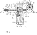
- the glue gun 1 comprises a housing 2 made of metal and/or plastic and the housing 2 delimits an interior space 5.
- the housing 5 also forms a handle 4 as a holding section 3.
- a battery 35 as a power supply unit 34 supplies electric power to the glue gun.
- An electronic control and/or regulation unit 33 controls and/or regulates the operation of the glue gun 1.
- a pultrusion unit 8 and an extrusion unit 9 are arranged inside the inner space 5 .
- a pultrusion channel 13 is formed in the pultrusion unit 8 and extends in a direction from right to left as shown in FIG 1 the pultrusion channel 13 first has a conically tapering section (not shown) and then a section with a constant diameter.
- a first heating device 12 and then a cooling device 14 are arranged from right to left as well as in a conveying direction of hybrid yarns 25 or the strand 36 to be produced 15, is passed through to cool the partially produced strand 36.
- the glue gun 1 can also be designed without the cooling device 14 and the cooling of the strand 36 takes place within a free space 23 between the pultrusion unit 8 and the extrusion unit 9.
- the extrusion unit 9 comprises an extrusion channel 21 and the extrusion channel 21 comprises a first conically tapering section (not shown) and a second section with a constant diameter.
- a second heating device 22 is formed on the second section of the extrusion channel 21 with the constant diameter.
- the first and second heating device 12, 22 is preferably designed as an electrical resistance heater 11.
- the conically tapering section of the extrusion channel 21 is formed first and then the section of the extrusion channel 21 with the constant diameter.
- a conveyor device 17 is formed in the free space 23 between the pultrusion unit 8 and the extrusion unit 9 .
- the conveyor device 17 comprises a first conveyor roller 19 and a second conveyor roller 20 which are driven by an electric motor 18 .
- the partially produced strand 36 is arranged between the two conveyor rollers 19, 20 so that the partially produced strand 36 is pulled out of the pultrusion unit 8 with the conveying device 17 and is pushed into the extrusion unit 9 with the conveying device 17 .
- the pultrusion unit 8 and the extrusion unit 9 are connected to one another with a connecting part, for example the housing 2 .
- Bearing means 6 are fixed as a bearing rod 7 on the housing 2 .
- a bobbin 24 is mounted on the bearing rod 7 or bearing stub 7 and a hybrid yarn 25 is wound or rolled up on the bobbin 24 .
- the hybrid yarn 25 consists of fibers as glass fibers and also has the matrix made of an unconsolidated thermoplastic material.
- the matrix as the thermoplastic material is arranged in the hybrid yarn 25 as a preferably fibrous or strand-like matrix or as a matrix fiber or matrix strand.
- the hybrid yarn 25 is flexible and can thus be unwound from the spool 24 .
- a cutting unit 26 serves to cut off the strand 36 extruded on the extrusion unit 9 .
- the cutting unit 26 comprises a moveable, bendable cutting socket 27 and the cutting socket 27 is mounted in a bearing channel or bearing tube and is moved by an electric motor 29 as a drive element 28 for the cutting unit 26 within the bearing channel.
- the storage channel is also partially curved and there is a crossing between the storage channel and the extrusion channel 21, so that the cutting connector 27 can also be inserted into the extrusion channel 21 to cut through the strand 36.
- a vibration motor 30 moves the cutting unit 26 during the cutting through of the Strand 36 in a vibrating or shaking motion, thereby improving the process of cutting. Deviating from this, the cutting unit 26 can also be formed on an outlet nozzle 10 (not shown).
- the Composite material as shown in 1 conveyed first through the pultrusion unit 8 and then through the extrusion unit 9 by means of the conveying device 17, however, due to the length of the strand 36 and the distance between the pultrusion unit 8 and the extrusion unit 9, both processes take place altogether simultaneously, but with respect to a fictitious point on the strand 36 sequentially in time.
- the hybrid yarn 25 is unwound from the spool 24 and introduced into the conically tapering section of the pultrusion channel 13 .
- the hybrid yarn 25 is heated with the first heating device 12, so that the thermoplastic material as the matrix on the hybrid yarn 25 melts and the glass fibers are thereby bonded to one another by means of the matrix made of the thermoplastic material as a pultrusion process.
- the composite material with the fibers and the thermoplastic material is then conveyed or moved to the section of the pultrusion channel 13 with the cooling device 14, so that the composite material with the glass fibers and the thermoplastic material is thereby cooled and thereby partially hardened.
- the composite material from the already partially produced strand 36 is conveyed or guided into the extrusion unit 9 by the conveying device 17 . Due to the cooling of the composite material with the fibers in the cooling device 14, the composite material can be conveyed by the conveyor device 17.
- the composite material with the fibers and the thermoplastic material is again slightly heated by the second heating device 22 in the section of the extrusion channel 21 with the constant diameter so that at the end area in the conveying direction of the extrusion channel 21 or the outlet nozzle 10 the final shaping of the cross-sectional shape of the strand 36 to be produced is formed.
- the left end of the extrusion channel 21 or the outlet nozzle 10 has a circular cross-sectional shape, so that thereby producing a strand 36 having a circular cross-section. After cooling, this strand 36 can no longer be bent because the thermoplastic material has consolidated. Due to the temperature of the strand 36 after exiting the outlet nozzle 10, the thermoplastic material acts as an adhesive, ie a material bond can easily be produced between the extruded strand 36, which is still at a high temperature, and a component in the area.
- the activation element 31 is connected to the control and/or regulating unit 33 by means of data lines (not shown).
- the control and/or regulating unit 33 controls the conveying device 17, the first heating device 12 and the second heating device 22 as well as the cooling device 14 automatically.
- the temperature in the pultrusion channel 13 and the extrusion channel 21 can be detected by means of temperature sensors (not shown).
- the control and/or regulation unit 33 first checks whether the temperature in the pultrusion channel 13 and the extrusion channel 21 is sufficient for melting the thermoplastic material.
- the pultrusion channel 13 and the extrusion channel 21 are first heated to the required temperature by means of the first heating device 12 and the second heating device 22 and only then is the conveying device 17 activated. If the temperature at the pultrusion channel 13 and the extrusion channel 21 is sufficient for melting the thermoplastic material, the conveyor device 17 is activated immediately after the activation element 31 is actuated. After the activation element 31 is released or deactivated, the conveyor device 17 is switched off and the Cutting unit 26 activated and also preferably the vibration motor 30 activated.
- An actuator 32 is additionally formed on the housing 2 . The conveying speed of the strand 36 can be controlled and/or regulated by the conveying device 17 by means of the actuator 32 .
- thermoplastic material can be stored on the glue gun 1 on the spool 24 since the hybrid yarn 25 is wound up on the spool 24 in a space-saving manner. Due to the use of the hybrid yarn 25 with fibers, in particular glass fibers, and the thermoplastic material as a thermoplastic adhesive, the strand 36 can be extruded from the composite material from the outlet nozzle 10 . Due to the arrangement of the fibers between the thermoplastic, this composite material has a very high tensile strength.
- components can also be cohesively connected to one another in an advantageous manner by means of the strand 36, for which it is necessary for the adhesive connection formed by the strand 36 to also be able to absorb high tensile forces.
- the strand 36 can thus be used not only for the simple production of an adhesive connection between two components, but also to be able to produce adhesive connections with a high tensile strength.
- corresponding reinforcement structures can also be formed on components that are already present by means of the strand 36 .
- the use of the glue gun 1 is thus significantly improved in terms of handling and also makes it possible to expand the field of application of the glue gun 1 to additional applications for the requirement of large tensile forces on the glued connection by means of the strand 36.
Landscapes
- Engineering & Computer Science (AREA)
- Mechanical Engineering (AREA)
- Chemical & Material Sciences (AREA)
- Composite Materials (AREA)
- Moulding By Coating Moulds (AREA)
- Extrusion Moulding Of Plastics Or The Like (AREA)
Claims (15)
- Pistolet à colle (1) pour un brin (36) comprenant de préférence une matière thermoplastique présentant une température de fusion, comprenant :- un boîtier (2),- au moins un moyen de stockage (6) pour le stockage du brin,- un dispositif de chauffage (12, 22),- une unité de pultrusion (8) avec un canal de pultrusion pour la consolidation du brin,- une unité d'extrusion (9) avec un canal d'extrusion pour la mise en forme et l'extrusion du brin (36),- un dispositif de transport (17) configuré pour transporter le brin à travers l'unité de pultrusion et à travers l'unité d'extrusion,- une buse de sortie (10) pour évacuer le brin chauffé du pistolet à colle, caractérisé en ce que le pistolet à colle comprend en outre :dans lequel l'unité de commande est configurée pour activer le dispositif de transport lorsqu'une première température dans le canal de pultrusion et une seconde température dans le canal d'extrusion sont suffisantes pour faire fondre la matière thermoplastique.- un capteur de température du canal de pultrusion,- un capteur de température de canal d'extrusion, et- une unité d'activation (31) connectée à une unité de commande (33), l'unité de commande étant configurée pour commander le dispositif de chauffage et le dispositif de transport et pour recevoir des entrées provenant du capteur de température du canal de pultrusion et du capteur de température du canal d'extrusion,
- Pistolet à colle selon la revendication 1,
caractérisé en ce que,
dans le sens de transport du brin, l'unité de pultrusion (8) est située avant l'unité d'extrusion (9). - Pistolet à colle selon la revendication 1 ou 2,
caractérisé en ce que
la buse de sortie (10) est située sur l'unité d'extrusion (9). - Pistolet à colle selon l'une ou plusieurs des revendications précédentes,
caractérisé en ce que
l'unité de pultrusion (8) comprend un premier dispositif de chauffage et l'unité d'extrusion comprend un deuxième dispositif de chauffage. - Pistolet à colle selon l'une ou plusieurs des revendications précédentes,
caractérisé en ce que
un espace libre (23) est présent entre l'unité de pultrusion (8) et l'unité d'extrusion (9), de sorte que le brin est disposé à l'intérieur de l'espace libre (23) après être sorti d'un canal de pultrusion (13) de l'unité de pultrusion (8) et avant d'être introduit dans un canal d'extrusion (21) de l'unité d'extrusion (9). - Pistolet à colle selon l'une ou plusieurs des revendications précédentes,
caractérisé en ce que
le dispositif de transport (17) est disposé entre l'unité de pultrusion (8) et l'unité d'extrusion (9), en particulier dans l'espace libre (23) entre l'unité de pultrusion (8) et l'unité d'extrusion (9). - Pistolet à colle selon l'une ou plusieurs des revendications précédentes,
caractérisé en ce que
le dispositif de transport (17) comprend au moins un rouleau de transport (19, 20). - Pistolet à colle selon la revendication 7,
caractérisé en ce que
le dispositif de convoyage (17) comprend deux rouleaux de convoyage (19, 20) pour disposer le brin (36) entre les deux rouleaux de convoyage (19, 20), en particulier la distance entre les surfaces de convoyage des deux rouleaux de convoyage (19, 20) pour l'appui sur le brin (36) correspond sensiblement au diamètre du canal de pultrusion (13) à une terminaison du canal de pultrusion (13) dans la direction de convoyage du brin et/ou correspond au diamètre du canal d'extrusion (21) à un début du canal d'extrusion (21) dans la direction de convoyage du brin. - Pistolet à colle selon l'une ou plusieurs des revendications précédentes,
caractérisé en ce que
le moyen de stockage (6) sert à stocker le brin enroulé sur une bobine (24). - Pistolet à colle selon l'une ou plusieurs des revendications précédentes,
caractérisé en ce que
le pistolet à colle comprend une bobine (24) sur laquelle est enroulé un brin de matière plastique non consolidée, de préférence thermoplastique ou thermodurcissable. - Pistolet à colle selon la revendication 10,
caractérisé en ce que
la matière plastique en forme de brin, de préférence thermoplastique ou thermodurcissable, est conçue comme un fil hybride (25) avec des fibres, en particulier des fibres de verre, des fibres de carbone et/ou des fibres d'aramide, et de la matière plastique, de préférence thermoplastique ou thermodurcissable. - Pistolet à colle selon l'une ou plusieurs des revendications précédentes,
caractérisé en ce que
le pistolet à colle (1) comprend une unité de coupe (26) pour couper le brin (36) de matière plastique, de préférence renforcée par des fibres. - Pistolet à colle selon l'une ou plusieurs des revendications précédentes,
caractérisé en ce que
le pistolet à colle (1) comprend un organe d'activation (31) pour mettre en marche et arrêter le pistolet à colle (1), en particulier les premier et deuxième dispositifs de chauffage (11, 12) et/ou le dispositif de transport (17). - Procédé de mise en oeuvre d'un pistolet à colle (1) selon l'une ou plusieurs des revendications précédentes, comprenant les étapes suivantes :- alimentation d'une unité de pultrusion (9) en fil hybride (25) comprenant des fibres et de la matière plastique, de préférence thermoplastique ou thermodurcissable,- chauffage du fil hybride (25) dans une unité de pultrusion (8), de sorte que les fibres et la matière plastique, de préférence thermoplastique ou thermodurcissable, soient liées entre elles par liaison de matière,- refroidissement du brin (36) de fibres et de matière plastique après chauffage dans l'unité de pultrusion (8),- fourniture du brin refroidi (36) de fibres et de matière plastique dans une unité d'extrusion (9),- chauffage du brin refroidi (36) de fibres et de matière plastique dans l'unité d'extrusion (9),- mise en forme de la forme de la section transversale du brin (36) de fibres et de matière plastique dans l'unité d'extrusion (9) et évacuation du brin (36) de fibres et de matière plastique au niveau d'une buse de sortie (10) de l'unité d'extrusion (9).
- Procédé selon la revendication 14, caractérisé en ce que le brin (36) de fibres et de matière plastique est refroidi dans un espace libre entre l'unité de pultrusion (8) et l'unité d'extrusion (9) et/ou est refroidi par un dispositif de refroidissement (14).
Applications Claiming Priority (2)
| Application Number | Priority Date | Filing Date | Title |
|---|---|---|---|
| DE102016008847.8A DE102016008847A1 (de) | 2016-07-23 | 2016-07-23 | Klebepistole |
| PCT/EP2017/000693 WO2018019398A1 (fr) | 2016-07-23 | 2017-06-14 | Pistolet à colle |
Publications (2)
| Publication Number | Publication Date |
|---|---|
| EP3487635A1 EP3487635A1 (fr) | 2019-05-29 |
| EP3487635B1 true EP3487635B1 (fr) | 2022-11-30 |
Family
ID=59366360
Family Applications (1)
| Application Number | Title | Priority Date | Filing Date |
|---|---|---|---|
| EP17740614.7A Active EP3487635B1 (fr) | 2016-07-23 | 2017-06-14 | Pistolet à colle |
Country Status (4)
| Country | Link |
|---|---|
| US (1) | US11141756B2 (fr) |
| EP (1) | EP3487635B1 (fr) |
| DE (1) | DE102016008847A1 (fr) |
| WO (1) | WO2018019398A1 (fr) |
Families Citing this family (3)
| Publication number | Priority date | Publication date | Assignee | Title |
|---|---|---|---|---|
| CN107159530A (zh) * | 2017-06-16 | 2017-09-15 | 奉化市威优特电器有限公司 | 一种热熔胶枪的加热装置 |
| EP3655219A4 (fr) * | 2017-07-17 | 2021-06-30 | Oceaneering International, Inc. | Appareil à adhésif thermofusible et procédé d'utilisation |
| US10413931B1 (en) | 2019-01-11 | 2019-09-17 | ACCO Brands Corporation | Glue gun with sequential stick feed |
Family Cites Families (11)
| Publication number | Priority date | Publication date | Assignee | Title |
|---|---|---|---|---|
| US5091036A (en) * | 1989-10-05 | 1992-02-25 | Taylor Scott R | Apparatus for pultruding thermoplastic structures at below melt temperatures |
| EP0423388A1 (fr) | 1989-10-18 | 1991-04-24 | STEINEL Entwicklungs-GmbH für Elektrotechnik und Elektronik | Pistolet à colle chauffé électriquement |
| US5026188A (en) * | 1989-12-11 | 1991-06-25 | Lockheed Corporation | Resin dispenser with combined cooling and heating tube |
| US6558059B1 (en) * | 2002-02-20 | 2003-05-06 | George Hillinger | Glue gun with pinch rollers |
| US7520408B1 (en) | 2005-10-13 | 2009-04-21 | Anthony Smith | Dripless hot glue gun |
| DE102007008722A1 (de) | 2007-02-22 | 2008-08-28 | Eschenbach, Wolfgang | Schnellklebepistole mit veränderbarer Geschwindigkeit |
| DE102008043031A1 (de) * | 2008-10-22 | 2010-04-29 | BSH Bosch und Siemens Hausgeräte GmbH | Verfahren zur Herstellung eines faserverstärkten Kunststoffprofiles |
| US9102098B2 (en) | 2012-12-05 | 2015-08-11 | Wobbleworks, Inc. | Hand-held three-dimensional drawing device |
| DE202013007889U1 (de) | 2013-09-06 | 2014-10-07 | Bühnen GmbH & Co. KG | Klebepistole |
| DE102014006706A1 (de) | 2014-05-09 | 2014-09-11 | Florian Eichenhofer | Verfahren zur Herstellung eines Fachwerkes |
| US9586229B1 (en) | 2015-09-22 | 2017-03-07 | Homeease Industrial Co., Ltd. | Hot melt glue gun with an automatic glue stick feeding structure |
-
2016
- 2016-07-23 DE DE102016008847.8A patent/DE102016008847A1/de not_active Withdrawn
-
2017
- 2017-06-14 US US16/317,960 patent/US11141756B2/en not_active Expired - Fee Related
- 2017-06-14 EP EP17740614.7A patent/EP3487635B1/fr active Active
- 2017-06-14 WO PCT/EP2017/000693 patent/WO2018019398A1/fr not_active Ceased
Also Published As
| Publication number | Publication date |
|---|---|
| WO2018019398A1 (fr) | 2018-02-01 |
| EP3487635A1 (fr) | 2019-05-29 |
| US20190224710A1 (en) | 2019-07-25 |
| US11141756B2 (en) | 2021-10-12 |
| DE102016008847A1 (de) | 2018-01-25 |
Similar Documents
| Publication | Publication Date | Title |
|---|---|---|
| EP3212388B1 (fr) | Production de plusieurs éléments composites fibreux différents en grandes séries dans un procédé continu | |
| EP3676075B1 (fr) | Procédé de pliage et dispositif de pliage pour plier une tige composite | |
| EP3487635B1 (fr) | Pistolet à colle | |
| EP3140108B1 (fr) | Procédé de fabrication d'un treillis | |
| EP2176059A1 (fr) | Procédé et dispositif de fabrication d'un produit composite renforcé | |
| EP3368259A1 (fr) | Système machine pour la fabrication d'une pièce hybride | |
| DE102016210040A1 (de) | Verfahren zum Herstellen eines zumindest bereichsweise profilierten, faserverstärkten Kunststoffprofils, ein profiliertes, faserverstärktes Kunststoffprofil und seine Verwendung | |
| WO2019185194A1 (fr) | Procédé et dispositif destinés à découper un extrudat | |
| DE102014006681B4 (de) | Vorrichtung zum Fügen flächiger Körper | |
| WO2011045172A1 (fr) | Tête d'amenée en dépôt, et procédé de dépôt contrôlé de faisceaux de fibres mis à longueur | |
| EP3424690A1 (fr) | Procédé et dispositif de fabrication d'une grille d'armature | |
| WO2021008896A1 (fr) | Procédé de production d'une pièce pliée et machine de pliage destinée à mettre en œuvre le procédé | |
| DE202014003925U1 (de) | Thermoplastischer flächiger Körperverbund und Einrichtung zum Fügen flächiger Körper | |
| EP3015255A1 (fr) | Fabrication d'éléments composites en fibres renforcés à certains endroits pour la production en grande série dans un processus continu et profilé creux rempli de mousse | |
| EP3808547B1 (fr) | Procédé et agencement d'outil permettant de fabriquer une structure de profilé composite fibre-matrice et structure de profilé composite fibre-matrice | |
| DE102018203704A1 (de) | Verfahren zum Herstellen eines Bauteils und Vorrichtung zum Herstellen eines Bauteils | |
| DE102005056123B4 (de) | Vorrichtung und Verfahren zur Montage einer Sprosse an einem Abstandhalter | |
| DE102016205531A1 (de) | Generatorkopf zur Erzeugung von stabförmigen Strukturelementen, Generator und Verfahren zur Erzeugung von stabförmigen Strukturelementen | |
| DE10146253C2 (de) | Verfahren zur Herstellung faserverstärkter Rohre | |
| EP4112274A1 (fr) | Structure de tête d'impression pour la fabrication additive au moyen de fibres sans fin et matériaux matriciels thermoplastiques permettant de couper dans la zone chaude de la tête d'impression au moyen d'un mouvement axial ou rotatif | |
| DE102016000703B4 (de) | Verfahren und Vorrichtung zur Herstellung eines Faserkunststoffverbund-Profils mit integrierten Lasteinleitungselementen | |
| DE102016117799A1 (de) | System und verfahren zur herstellung eines faserverbundhalbzeugs sowie ein verfahren zur herstellung eines faserverbundbauteils | |
| DE102017111230A1 (de) | Formkörper und Verfahren zur Herstellung eines Formkörpers | |
| DE102024105662A1 (de) | Verfahren und Anordnung für die Herstellung von Profilen aus faserverstärkten Kunststoffen | |
| DE102018121852A1 (de) | Verfahren zum Herstellen von Blattfedern in Faserverbundbauweise und Strangziehvorrichtung |
Legal Events
| Date | Code | Title | Description |
|---|---|---|---|
| STAA | Information on the status of an ep patent application or granted ep patent |
Free format text: STATUS: UNKNOWN |
|
| STAA | Information on the status of an ep patent application or granted ep patent |
Free format text: STATUS: THE INTERNATIONAL PUBLICATION HAS BEEN MADE |
|
| PUAI | Public reference made under article 153(3) epc to a published international application that has entered the european phase |
Free format text: ORIGINAL CODE: 0009012 |
|
| STAA | Information on the status of an ep patent application or granted ep patent |
Free format text: STATUS: REQUEST FOR EXAMINATION WAS MADE |
|
| 17P | Request for examination filed |
Effective date: 20190115 |
|
| AK | Designated contracting states |
Kind code of ref document: A1 Designated state(s): AL AT BE BG CH CY CZ DE DK EE ES FI FR GB GR HR HU IE IS IT LI LT LU LV MC MK MT NL NO PL PT RO RS SE SI SK SM TR |
|
| AX | Request for extension of the european patent |
Extension state: BA ME |
|
| DAV | Request for validation of the european patent (deleted) | ||
| DAX | Request for extension of the european patent (deleted) | ||
| RAP1 | Party data changed (applicant data changed or rights of an application transferred) |
Owner name: 9T LABS AG |
|
| STAA | Information on the status of an ep patent application or granted ep patent |
Free format text: STATUS: EXAMINATION IS IN PROGRESS |
|
| 17Q | First examination report despatched |
Effective date: 20211209 |
|
| GRAP | Despatch of communication of intention to grant a patent |
Free format text: ORIGINAL CODE: EPIDOSNIGR1 |
|
| STAA | Information on the status of an ep patent application or granted ep patent |
Free format text: STATUS: GRANT OF PATENT IS INTENDED |
|
| INTG | Intention to grant announced |
Effective date: 20220825 |
|
| GRAS | Grant fee paid |
Free format text: ORIGINAL CODE: EPIDOSNIGR3 |
|
| GRAA | (expected) grant |
Free format text: ORIGINAL CODE: 0009210 |
|
| STAA | Information on the status of an ep patent application or granted ep patent |
Free format text: STATUS: THE PATENT HAS BEEN GRANTED |
|
| AK | Designated contracting states |
Kind code of ref document: B1 Designated state(s): AL AT BE BG CH CY CZ DE DK EE ES FI FR GB GR HR HU IE IS IT LI LT LU LV MC MK MT NL NO PL PT RO RS SE SI SK SM TR |
|
| REG | Reference to a national code |
Ref country code: CH Ref legal event code: EP Ref country code: GB Ref legal event code: FG4D Free format text: NOT ENGLISH |
|
| REG | Reference to a national code |
Ref country code: AT Ref legal event code: REF Ref document number: 1534273 Country of ref document: AT Kind code of ref document: T Effective date: 20221215 |
|
| REG | Reference to a national code |
Ref country code: IE Ref legal event code: FG4D Free format text: LANGUAGE OF EP DOCUMENT: GERMAN |
|
| REG | Reference to a national code |
Ref country code: DE Ref legal event code: R096 Ref document number: 502017014159 Country of ref document: DE |
|
| REG | Reference to a national code |
Ref country code: LT Ref legal event code: MG9D |
|
| REG | Reference to a national code |
Ref country code: NL Ref legal event code: MP Effective date: 20221130 |
|
| PG25 | Lapsed in a contracting state [announced via postgrant information from national office to epo] |
Ref country code: SE Free format text: LAPSE BECAUSE OF FAILURE TO SUBMIT A TRANSLATION OF THE DESCRIPTION OR TO PAY THE FEE WITHIN THE PRESCRIBED TIME-LIMIT Effective date: 20221130 Ref country code: PT Free format text: LAPSE BECAUSE OF FAILURE TO SUBMIT A TRANSLATION OF THE DESCRIPTION OR TO PAY THE FEE WITHIN THE PRESCRIBED TIME-LIMIT Effective date: 20230331 Ref country code: NO Free format text: LAPSE BECAUSE OF FAILURE TO SUBMIT A TRANSLATION OF THE DESCRIPTION OR TO PAY THE FEE WITHIN THE PRESCRIBED TIME-LIMIT Effective date: 20230228 Ref country code: LT Free format text: LAPSE BECAUSE OF FAILURE TO SUBMIT A TRANSLATION OF THE DESCRIPTION OR TO PAY THE FEE WITHIN THE PRESCRIBED TIME-LIMIT Effective date: 20221130 Ref country code: FI Free format text: LAPSE BECAUSE OF FAILURE TO SUBMIT A TRANSLATION OF THE DESCRIPTION OR TO PAY THE FEE WITHIN THE PRESCRIBED TIME-LIMIT Effective date: 20221130 Ref country code: ES Free format text: LAPSE BECAUSE OF FAILURE TO SUBMIT A TRANSLATION OF THE DESCRIPTION OR TO PAY THE FEE WITHIN THE PRESCRIBED TIME-LIMIT Effective date: 20221130 |
|
| PG25 | Lapsed in a contracting state [announced via postgrant information from national office to epo] |
Ref country code: RS Free format text: LAPSE BECAUSE OF FAILURE TO SUBMIT A TRANSLATION OF THE DESCRIPTION OR TO PAY THE FEE WITHIN THE PRESCRIBED TIME-LIMIT Effective date: 20221130 Ref country code: PL Free format text: LAPSE BECAUSE OF FAILURE TO SUBMIT A TRANSLATION OF THE DESCRIPTION OR TO PAY THE FEE WITHIN THE PRESCRIBED TIME-LIMIT Effective date: 20221130 Ref country code: LV Free format text: LAPSE BECAUSE OF FAILURE TO SUBMIT A TRANSLATION OF THE DESCRIPTION OR TO PAY THE FEE WITHIN THE PRESCRIBED TIME-LIMIT Effective date: 20221130 Ref country code: IS Free format text: LAPSE BECAUSE OF FAILURE TO SUBMIT A TRANSLATION OF THE DESCRIPTION OR TO PAY THE FEE WITHIN THE PRESCRIBED TIME-LIMIT Effective date: 20230330 Ref country code: HR Free format text: LAPSE BECAUSE OF FAILURE TO SUBMIT A TRANSLATION OF THE DESCRIPTION OR TO PAY THE FEE WITHIN THE PRESCRIBED TIME-LIMIT Effective date: 20221130 Ref country code: GR Free format text: LAPSE BECAUSE OF FAILURE TO SUBMIT A TRANSLATION OF THE DESCRIPTION OR TO PAY THE FEE WITHIN THE PRESCRIBED TIME-LIMIT Effective date: 20230301 |
|
| PG25 | Lapsed in a contracting state [announced via postgrant information from national office to epo] |
Ref country code: NL Free format text: LAPSE BECAUSE OF FAILURE TO SUBMIT A TRANSLATION OF THE DESCRIPTION OR TO PAY THE FEE WITHIN THE PRESCRIBED TIME-LIMIT Effective date: 20221130 |
|
| PG25 | Lapsed in a contracting state [announced via postgrant information from national office to epo] |
Ref country code: SM Free format text: LAPSE BECAUSE OF FAILURE TO SUBMIT A TRANSLATION OF THE DESCRIPTION OR TO PAY THE FEE WITHIN THE PRESCRIBED TIME-LIMIT Effective date: 20221130 Ref country code: RO Free format text: LAPSE BECAUSE OF FAILURE TO SUBMIT A TRANSLATION OF THE DESCRIPTION OR TO PAY THE FEE WITHIN THE PRESCRIBED TIME-LIMIT Effective date: 20221130 Ref country code: EE Free format text: LAPSE BECAUSE OF FAILURE TO SUBMIT A TRANSLATION OF THE DESCRIPTION OR TO PAY THE FEE WITHIN THE PRESCRIBED TIME-LIMIT Effective date: 20221130 Ref country code: DK Free format text: LAPSE BECAUSE OF FAILURE TO SUBMIT A TRANSLATION OF THE DESCRIPTION OR TO PAY THE FEE WITHIN THE PRESCRIBED TIME-LIMIT Effective date: 20221130 Ref country code: CZ Free format text: LAPSE BECAUSE OF FAILURE TO SUBMIT A TRANSLATION OF THE DESCRIPTION OR TO PAY THE FEE WITHIN THE PRESCRIBED TIME-LIMIT Effective date: 20221130 |
|
| PG25 | Lapsed in a contracting state [announced via postgrant information from national office to epo] |
Ref country code: SK Free format text: LAPSE BECAUSE OF FAILURE TO SUBMIT A TRANSLATION OF THE DESCRIPTION OR TO PAY THE FEE WITHIN THE PRESCRIBED TIME-LIMIT Effective date: 20221130 Ref country code: AL Free format text: LAPSE BECAUSE OF FAILURE TO SUBMIT A TRANSLATION OF THE DESCRIPTION OR TO PAY THE FEE WITHIN THE PRESCRIBED TIME-LIMIT Effective date: 20221130 |
|
| REG | Reference to a national code |
Ref country code: DE Ref legal event code: R097 Ref document number: 502017014159 Country of ref document: DE |
|
| PLBE | No opposition filed within time limit |
Free format text: ORIGINAL CODE: 0009261 |
|
| STAA | Information on the status of an ep patent application or granted ep patent |
Free format text: STATUS: NO OPPOSITION FILED WITHIN TIME LIMIT |
|
| 26N | No opposition filed |
Effective date: 20230831 |
|
| PG25 | Lapsed in a contracting state [announced via postgrant information from national office to epo] |
Ref country code: SI Free format text: LAPSE BECAUSE OF FAILURE TO SUBMIT A TRANSLATION OF THE DESCRIPTION OR TO PAY THE FEE WITHIN THE PRESCRIBED TIME-LIMIT Effective date: 20221130 |
|
| PG25 | Lapsed in a contracting state [announced via postgrant information from national office to epo] |
Ref country code: MC Free format text: LAPSE BECAUSE OF FAILURE TO SUBMIT A TRANSLATION OF THE DESCRIPTION OR TO PAY THE FEE WITHIN THE PRESCRIBED TIME-LIMIT Effective date: 20221130 |
|
| PG25 | Lapsed in a contracting state [announced via postgrant information from national office to epo] |
Ref country code: MC Free format text: LAPSE BECAUSE OF FAILURE TO SUBMIT A TRANSLATION OF THE DESCRIPTION OR TO PAY THE FEE WITHIN THE PRESCRIBED TIME-LIMIT Effective date: 20221130 |
|
| REG | Reference to a national code |
Ref country code: BE Ref legal event code: MM Effective date: 20230630 |
|
| PG25 | Lapsed in a contracting state [announced via postgrant information from national office to epo] |
Ref country code: LU Free format text: LAPSE BECAUSE OF NON-PAYMENT OF DUE FEES Effective date: 20230614 |
|
| REG | Reference to a national code |
Ref country code: IE Ref legal event code: MM4A |
|
| PG25 | Lapsed in a contracting state [announced via postgrant information from national office to epo] |
Ref country code: LU Free format text: LAPSE BECAUSE OF NON-PAYMENT OF DUE FEES Effective date: 20230614 |
|
| PG25 | Lapsed in a contracting state [announced via postgrant information from national office to epo] |
Ref country code: IE Free format text: LAPSE BECAUSE OF NON-PAYMENT OF DUE FEES Effective date: 20230614 |
|
| PG25 | Lapsed in a contracting state [announced via postgrant information from national office to epo] |
Ref country code: IE Free format text: LAPSE BECAUSE OF NON-PAYMENT OF DUE FEES Effective date: 20230614 |
|
| PG25 | Lapsed in a contracting state [announced via postgrant information from national office to epo] |
Ref country code: IT Free format text: LAPSE BECAUSE OF FAILURE TO SUBMIT A TRANSLATION OF THE DESCRIPTION OR TO PAY THE FEE WITHIN THE PRESCRIBED TIME-LIMIT Effective date: 20221130 Ref country code: BE Free format text: LAPSE BECAUSE OF NON-PAYMENT OF DUE FEES Effective date: 20230630 |
|
| PGFP | Annual fee paid to national office [announced via postgrant information from national office to epo] |
Ref country code: GB Payment date: 20240620 Year of fee payment: 8 |
|
| PGFP | Annual fee paid to national office [announced via postgrant information from national office to epo] |
Ref country code: DE Payment date: 20240617 Year of fee payment: 8 |
|
| PGFP | Annual fee paid to national office [announced via postgrant information from national office to epo] |
Ref country code: FR Payment date: 20240621 Year of fee payment: 8 |
|
| REG | Reference to a national code |
Ref country code: AT Ref legal event code: MM01 Ref document number: 1534273 Country of ref document: AT Kind code of ref document: T Effective date: 20230614 |
|
| PGFP | Annual fee paid to national office [announced via postgrant information from national office to epo] |
Ref country code: CH Payment date: 20240701 Year of fee payment: 8 |
|
| PG25 | Lapsed in a contracting state [announced via postgrant information from national office to epo] |
Ref country code: AT Free format text: LAPSE BECAUSE OF NON-PAYMENT OF DUE FEES Effective date: 20230614 |
|
| PG25 | Lapsed in a contracting state [announced via postgrant information from national office to epo] |
Ref country code: AT Free format text: LAPSE BECAUSE OF NON-PAYMENT OF DUE FEES Effective date: 20230614 |
|
| PG25 | Lapsed in a contracting state [announced via postgrant information from national office to epo] |
Ref country code: BG Free format text: LAPSE BECAUSE OF FAILURE TO SUBMIT A TRANSLATION OF THE DESCRIPTION OR TO PAY THE FEE WITHIN THE PRESCRIBED TIME-LIMIT Effective date: 20221130 |
|
| PG25 | Lapsed in a contracting state [announced via postgrant information from national office to epo] |
Ref country code: BG Free format text: LAPSE BECAUSE OF FAILURE TO SUBMIT A TRANSLATION OF THE DESCRIPTION OR TO PAY THE FEE WITHIN THE PRESCRIBED TIME-LIMIT Effective date: 20221130 |
|
| PG25 | Lapsed in a contracting state [announced via postgrant information from national office to epo] |
Ref country code: CY Free format text: LAPSE BECAUSE OF FAILURE TO SUBMIT A TRANSLATION OF THE DESCRIPTION OR TO PAY THE FEE WITHIN THE PRESCRIBED TIME-LIMIT; INVALID AB INITIO Effective date: 20170614 |
|
| PG25 | Lapsed in a contracting state [announced via postgrant information from national office to epo] |
Ref country code: HU Free format text: LAPSE BECAUSE OF FAILURE TO SUBMIT A TRANSLATION OF THE DESCRIPTION OR TO PAY THE FEE WITHIN THE PRESCRIBED TIME-LIMIT; INVALID AB INITIO Effective date: 20170614 |
|
| PG25 | Lapsed in a contracting state [announced via postgrant information from national office to epo] |
Ref country code: TR Free format text: LAPSE BECAUSE OF FAILURE TO SUBMIT A TRANSLATION OF THE DESCRIPTION OR TO PAY THE FEE WITHIN THE PRESCRIBED TIME-LIMIT Effective date: 20221130 |
|
| REG | Reference to a national code |
Ref country code: DE Ref legal event code: R119 Ref document number: 502017014159 Country of ref document: DE |
|
| REG | Reference to a national code |
Ref country code: CH Ref legal event code: H13 Free format text: ST27 STATUS EVENT CODE: U-0-0-H10-H13 (AS PROVIDED BY THE NATIONAL OFFICE) Effective date: 20260127 |
|
| GBPC | Gb: european patent ceased through non-payment of renewal fee |
Effective date: 20250614 |
|
| PG25 | Lapsed in a contracting state [announced via postgrant information from national office to epo] |
Ref country code: GB Free format text: LAPSE BECAUSE OF NON-PAYMENT OF DUE FEES Effective date: 20250614 |
|
| PG25 | Lapsed in a contracting state [announced via postgrant information from national office to epo] |
Ref country code: DE Free format text: LAPSE BECAUSE OF NON-PAYMENT OF DUE FEES Effective date: 20260101 |
|
| PG25 | Lapsed in a contracting state [announced via postgrant information from national office to epo] |
Ref country code: FR Free format text: LAPSE BECAUSE OF NON-PAYMENT OF DUE FEES Effective date: 20250630 |
|
| PG25 | Lapsed in a contracting state [announced via postgrant information from national office to epo] |
Ref country code: CH Free format text: LAPSE BECAUSE OF NON-PAYMENT OF DUE FEES Effective date: 20250630 |