EP3486644B1 - Electrochemical cell comprising thin planar secondary wick - Google Patents
Electrochemical cell comprising thin planar secondary wick Download PDFInfo
- Publication number
- EP3486644B1 EP3486644B1 EP18213183.9A EP18213183A EP3486644B1 EP 3486644 B1 EP3486644 B1 EP 3486644B1 EP 18213183 A EP18213183 A EP 18213183A EP 3486644 B1 EP3486644 B1 EP 3486644B1
- Authority
- EP
- European Patent Office
- Prior art keywords
- wick
- cell
- gas
- electrolyte
- electrode
- Prior art date
- Legal status (The legal status is an assumption and is not a legal conclusion. Google has not performed a legal analysis and makes no representation as to the accuracy of the status listed.)
- Active
Links
- 239000003792 electrolyte Substances 0.000 claims description 91
- 238000004891 communication Methods 0.000 claims description 11
- 239000012530 fluid Substances 0.000 claims description 11
- 210000004027 cell Anatomy 0.000 description 174
- 239000007789 gas Substances 0.000 description 162
- 239000001301 oxygen Substances 0.000 description 45
- 229910052760 oxygen Inorganic materials 0.000 description 45
- QVGXLLKOCUKJST-UHFFFAOYSA-N atomic oxygen Chemical compound [O] QVGXLLKOCUKJST-UHFFFAOYSA-N 0.000 description 42
- 239000012528 membrane Substances 0.000 description 26
- 229910002091 carbon monoxide Inorganic materials 0.000 description 23
- UGFAIRIUMAVXCW-UHFFFAOYSA-N Carbon monoxide Chemical compound [O+]#[C-] UGFAIRIUMAVXCW-UHFFFAOYSA-N 0.000 description 22
- 239000003054 catalyst Substances 0.000 description 12
- 239000002253 acid Substances 0.000 description 10
- 238000009792 diffusion process Methods 0.000 description 10
- 230000000694 effects Effects 0.000 description 10
- 239000000758 substrate Substances 0.000 description 9
- 230000036571 hydration Effects 0.000 description 8
- 238000006703 hydration reaction Methods 0.000 description 8
- 239000000463 material Substances 0.000 description 8
- 239000000376 reactant Substances 0.000 description 8
- RAHZWNYVWXNFOC-UHFFFAOYSA-N Sulphur dioxide Chemical compound O=S=O RAHZWNYVWXNFOC-UHFFFAOYSA-N 0.000 description 6
- 238000006243 chemical reaction Methods 0.000 description 6
- 235000003642 hunger Nutrition 0.000 description 6
- LELOWRISYMNNSU-UHFFFAOYSA-N hydrogen cyanide Chemical compound N#C LELOWRISYMNNSU-UHFFFAOYSA-N 0.000 description 6
- 230000037351 starvation Effects 0.000 description 6
- XLYOFNOQVPJJNP-UHFFFAOYSA-N water Substances O XLYOFNOQVPJJNP-UHFFFAOYSA-N 0.000 description 6
- 230000008859 change Effects 0.000 description 5
- 238000001514 detection method Methods 0.000 description 5
- QGZKDVFQNNGYKY-UHFFFAOYSA-N Ammonia Chemical compound N QGZKDVFQNNGYKY-UHFFFAOYSA-N 0.000 description 4
- OKTJSMMVPCPJKN-UHFFFAOYSA-N Carbon Chemical compound [C] OKTJSMMVPCPJKN-UHFFFAOYSA-N 0.000 description 4
- OAKJQQAXSVQMHS-UHFFFAOYSA-N Hydrazine Chemical compound NN OAKJQQAXSVQMHS-UHFFFAOYSA-N 0.000 description 4
- MWUXSHHQAYIFBG-UHFFFAOYSA-N Nitric oxide Chemical compound O=[N] MWUXSHHQAYIFBG-UHFFFAOYSA-N 0.000 description 4
- 210000005056 cell body Anatomy 0.000 description 4
- 230000007423 decrease Effects 0.000 description 4
- 238000013461 design Methods 0.000 description 4
- 239000001257 hydrogen Substances 0.000 description 4
- 229910052739 hydrogen Inorganic materials 0.000 description 4
- 239000007788 liquid Substances 0.000 description 4
- 229910052751 metal Inorganic materials 0.000 description 4
- 239000002184 metal Substances 0.000 description 4
- 239000000203 mixture Substances 0.000 description 4
- 239000007787 solid Substances 0.000 description 4
- RWSOTUBLDIXVET-UHFFFAOYSA-N Dihydrogen sulfide Chemical compound S RWSOTUBLDIXVET-UHFFFAOYSA-N 0.000 description 3
- MYMOFIZGZYHOMD-UHFFFAOYSA-N Dioxygen Chemical compound O=O MYMOFIZGZYHOMD-UHFFFAOYSA-N 0.000 description 3
- VEXZGXHMUGYJMC-UHFFFAOYSA-N Hydrochloric acid Chemical compound Cl VEXZGXHMUGYJMC-UHFFFAOYSA-N 0.000 description 3
- CPELXLSAUQHCOX-UHFFFAOYSA-N Hydrogen bromide Chemical compound Br CPELXLSAUQHCOX-UHFFFAOYSA-N 0.000 description 3
- XYFCBTPGUUZFHI-UHFFFAOYSA-N Phosphine Chemical compound P XYFCBTPGUUZFHI-UHFFFAOYSA-N 0.000 description 3
- XECAHXYUAAWDEL-UHFFFAOYSA-N acrylonitrile butadiene styrene Chemical compound C=CC=C.C=CC#N.C=CC1=CC=CC=C1 XECAHXYUAAWDEL-UHFFFAOYSA-N 0.000 description 3
- 229920000122 acrylonitrile butadiene styrene Polymers 0.000 description 3
- 239000004676 acrylonitrile butadiene styrene Substances 0.000 description 3
- RBFQJDQYXXHULB-UHFFFAOYSA-N arsane Chemical compound [AsH3] RBFQJDQYXXHULB-UHFFFAOYSA-N 0.000 description 3
- 229910001882 dioxygen Inorganic materials 0.000 description 3
- 229910000041 hydrogen chloride Inorganic materials 0.000 description 3
- IXCSERBJSXMMFS-UHFFFAOYSA-N hydrogen chloride Substances Cl.Cl IXCSERBJSXMMFS-UHFFFAOYSA-N 0.000 description 3
- -1 hydrogen ions Chemical class 0.000 description 3
- 239000011244 liquid electrolyte Substances 0.000 description 3
- 238000005259 measurement Methods 0.000 description 3
- 150000002926 oxygen Chemical class 0.000 description 3
- 239000012466 permeate Substances 0.000 description 3
- 229910000065 phosphene Inorganic materials 0.000 description 3
- 239000004810 polytetrafluoroethylene Substances 0.000 description 3
- 229920001343 polytetrafluoroethylene Polymers 0.000 description 3
- 238000007789 sealing Methods 0.000 description 3
- 239000004291 sulphur dioxide Substances 0.000 description 3
- 238000012360 testing method Methods 0.000 description 3
- ZAMOUSCENKQFHK-UHFFFAOYSA-N Chlorine atom Chemical compound [Cl] ZAMOUSCENKQFHK-UHFFFAOYSA-N 0.000 description 2
- KRHYYFGTRYWZRS-UHFFFAOYSA-N Fluorane Chemical compound F KRHYYFGTRYWZRS-UHFFFAOYSA-N 0.000 description 2
- PXGOKWXKJXAPGV-UHFFFAOYSA-N Fluorine Chemical compound FF PXGOKWXKJXAPGV-UHFFFAOYSA-N 0.000 description 2
- LSDPWZHWYPCBBB-UHFFFAOYSA-N Methanethiol Chemical compound SC LSDPWZHWYPCBBB-UHFFFAOYSA-N 0.000 description 2
- YGYAWVDWMABLBF-UHFFFAOYSA-N Phosgene Chemical compound ClC(Cl)=O YGYAWVDWMABLBF-UHFFFAOYSA-N 0.000 description 2
- 206010034962 Photopsia Diseases 0.000 description 2
- BLRPTPMANUNPDV-UHFFFAOYSA-N Silane Chemical compound [SiH4] BLRPTPMANUNPDV-UHFFFAOYSA-N 0.000 description 2
- QAOWNCQODCNURD-UHFFFAOYSA-N Sulfuric acid Chemical compound OS(O)(=O)=O QAOWNCQODCNURD-UHFFFAOYSA-N 0.000 description 2
- 238000010521 absorption reaction Methods 0.000 description 2
- 229910021529 ammonia Inorganic materials 0.000 description 2
- 239000002041 carbon nanotube Substances 0.000 description 2
- 229910021393 carbon nanotube Inorganic materials 0.000 description 2
- 239000000460 chlorine Substances 0.000 description 2
- 229910052801 chlorine Inorganic materials 0.000 description 2
- 239000004020 conductor Substances 0.000 description 2
- 230000001419 dependent effect Effects 0.000 description 2
- OSVXSBDYLRYLIG-UHFFFAOYSA-N dioxidochlorine(.) Chemical compound O=Cl=O OSVXSBDYLRYLIG-UHFFFAOYSA-N 0.000 description 2
- 230000007613 environmental effect Effects 0.000 description 2
- 239000011737 fluorine Substances 0.000 description 2
- 229910052731 fluorine Inorganic materials 0.000 description 2
- XLYOFNOQVPJJNP-ZSJDYOACSA-N heavy water Substances [2H]O[2H] XLYOFNOQVPJJNP-ZSJDYOACSA-N 0.000 description 2
- 150000002431 hydrogen Chemical class 0.000 description 2
- 229910000040 hydrogen fluoride Inorganic materials 0.000 description 2
- AMXOYNBUYSYVKV-UHFFFAOYSA-M lithium bromide Chemical compound [Li+].[Br-] AMXOYNBUYSYVKV-UHFFFAOYSA-M 0.000 description 2
- BASFCYQUMIYNBI-UHFFFAOYSA-N platinum Chemical compound [Pt] BASFCYQUMIYNBI-UHFFFAOYSA-N 0.000 description 2
- SPVXKVOXSXTJOY-UHFFFAOYSA-N selane Chemical compound [SeH2] SPVXKVOXSXTJOY-UHFFFAOYSA-N 0.000 description 2
- 229910000058 selane Inorganic materials 0.000 description 2
- 229910000077 silane Inorganic materials 0.000 description 2
- 235000010269 sulphur dioxide Nutrition 0.000 description 2
- 235000011149 sulphuric acid Nutrition 0.000 description 2
- 239000001117 sulphuric acid Substances 0.000 description 2
- MGWGWNFMUOTEHG-UHFFFAOYSA-N 4-(3,5-dimethylphenyl)-1,3-thiazol-2-amine Chemical compound CC1=CC(C)=CC(C=2N=C(N)SC=2)=C1 MGWGWNFMUOTEHG-UHFFFAOYSA-N 0.000 description 1
- KZBUYRJDOAKODT-UHFFFAOYSA-N Chlorine Chemical compound ClCl KZBUYRJDOAKODT-UHFFFAOYSA-N 0.000 description 1
- 239000004155 Chlorine dioxide Substances 0.000 description 1
- IAYPIBMASNFSPL-UHFFFAOYSA-N Ethylene oxide Chemical compound C1CO1 IAYPIBMASNFSPL-UHFFFAOYSA-N 0.000 description 1
- UFHFLCQGNIYNRP-UHFFFAOYSA-N Hydrogen Chemical compound [H][H] UFHFLCQGNIYNRP-UHFFFAOYSA-N 0.000 description 1
- CBENFWSGALASAD-UHFFFAOYSA-N Ozone Chemical compound [O-][O+]=O CBENFWSGALASAD-UHFFFAOYSA-N 0.000 description 1
- 238000004026 adhesive bonding Methods 0.000 description 1
- 239000007864 aqueous solution Substances 0.000 description 1
- 229910000070 arsenic hydride Inorganic materials 0.000 description 1
- 230000009286 beneficial effect Effects 0.000 description 1
- 239000003990 capacitor Substances 0.000 description 1
- 229910052799 carbon Inorganic materials 0.000 description 1
- 230000003197 catalytic effect Effects 0.000 description 1
- 210000003850 cellular structure Anatomy 0.000 description 1
- 235000019398 chlorine dioxide Nutrition 0.000 description 1
- 239000000470 constituent Substances 0.000 description 1
- 230000003247 decreasing effect Effects 0.000 description 1
- 230000018044 dehydration Effects 0.000 description 1
- 238000006297 dehydration reaction Methods 0.000 description 1
- 238000003795 desorption Methods 0.000 description 1
- 238000011161 development Methods 0.000 description 1
- 230000002900 effect on cell Effects 0.000 description 1
- 238000001914 filtration Methods 0.000 description 1
- 239000008246 gaseous mixture Substances 0.000 description 1
- 239000003365 glass fiber Substances 0.000 description 1
- 229910002804 graphite Inorganic materials 0.000 description 1
- 239000010439 graphite Substances 0.000 description 1
- 229910000042 hydrogen bromide Inorganic materials 0.000 description 1
- 230000006872 improvement Effects 0.000 description 1
- 238000009434 installation Methods 0.000 description 1
- 239000002608 ionic liquid Substances 0.000 description 1
- 150000002500 ions Chemical class 0.000 description 1
- 230000001788 irregular Effects 0.000 description 1
- 238000004519 manufacturing process Methods 0.000 description 1
- 230000007246 mechanism Effects 0.000 description 1
- 238000000034 method Methods 0.000 description 1
- 230000004048 modification Effects 0.000 description 1
- 238000012986 modification Methods 0.000 description 1
- 230000007935 neutral effect Effects 0.000 description 1
- JCXJVPUVTGWSNB-UHFFFAOYSA-N nitrogen dioxide Inorganic materials O=[N]=O JCXJVPUVTGWSNB-UHFFFAOYSA-N 0.000 description 1
- 239000011255 nonaqueous electrolyte Substances 0.000 description 1
- 230000036284 oxygen consumption Effects 0.000 description 1
- 239000004033 plastic Substances 0.000 description 1
- 229920003023 plastic Polymers 0.000 description 1
- 229910052697 platinum Inorganic materials 0.000 description 1
- 231100000614 poison Toxicity 0.000 description 1
- 230000007096 poisonous effect Effects 0.000 description 1
- 230000008707 rearrangement Effects 0.000 description 1
- 230000009467 reduction Effects 0.000 description 1
- 239000000126 substance Substances 0.000 description 1
- 230000002277 temperature effect Effects 0.000 description 1
- 238000003466 welding Methods 0.000 description 1
Images


Classifications
-
- G—PHYSICS
- G01—MEASURING; TESTING
- G01N—INVESTIGATING OR ANALYSING MATERIALS BY DETERMINING THEIR CHEMICAL OR PHYSICAL PROPERTIES
- G01N27/00—Investigating or analysing materials by the use of electric, electrochemical, or magnetic means
- G01N27/26—Investigating or analysing materials by the use of electric, electrochemical, or magnetic means by investigating electrochemical variables; by using electrolysis or electrophoresis
- G01N27/403—Cells and electrode assemblies
- G01N27/404—Cells with anode, cathode and cell electrolyte on the same side of a permeable membrane which separates them from the sample fluid, e.g. Clark-type oxygen sensors
- G01N27/4045—Cells with anode, cathode and cell electrolyte on the same side of a permeable membrane which separates them from the sample fluid, e.g. Clark-type oxygen sensors for gases other than oxygen
-
- G—PHYSICS
- G01—MEASURING; TESTING
- G01N—INVESTIGATING OR ANALYSING MATERIALS BY DETERMINING THEIR CHEMICAL OR PHYSICAL PROPERTIES
- G01N27/00—Investigating or analysing materials by the use of electric, electrochemical, or magnetic means
- G01N27/26—Investigating or analysing materials by the use of electric, electrochemical, or magnetic means by investigating electrochemical variables; by using electrolysis or electrophoresis
- G01N27/403—Cells and electrode assemblies
- G01N27/413—Concentration cells using liquid electrolytes measuring currents or voltages in voltaic cells
-
- G—PHYSICS
- G01—MEASURING; TESTING
- G01N—INVESTIGATING OR ANALYSING MATERIALS BY DETERMINING THEIR CHEMICAL OR PHYSICAL PROPERTIES
- G01N33/00—Investigating or analysing materials by specific methods not covered by groups G01N1/00 - G01N31/00
- G01N33/0004—Gaseous mixtures, e.g. polluted air
- G01N33/0009—General constructional details of gas analysers, e.g. portable test equipment
- G01N33/0027—General constructional details of gas analysers, e.g. portable test equipment concerning the detector
- G01N33/0036—Specially adapted to detect a particular component
- G01N33/004—Specially adapted to detect a particular component for CO, CO2
Definitions
- the present invention relates to an electrochemical cell for use in a gas detector as defined in claim 1. Details of the electrochemical cell are defined in dependent claims 2-10 and a gas detector comprising the electrochemical cell is defined in claim 11.
- Amperometric electrochemical cells have found widespread use for the detection of various gases in the environment, including use for the detection of carbon monoxide in the domestic environment.
- a typical cell 10 comprises two or three gas electrodes - a working or sensing electrode 12, a counter electrode 14 and, optionally, a reference electrode (not shown).
- the reference electrode is often omitted and the counter electrode serves as a combined counter/reference electrode. All three (two) of these electrodes comprise a very high surface area catalytic metal (or other conductive material) 12, 14 supported on a gas permeable membrane or substrate 18, 20.
- An electrolyte 16, for example an acid, is typically completely contained within a wick 17 at a condition of lowest humidity. The wick 17 acts to hold and supply electrolyte to the sensing electrode 12 such that the chemical reaction discussed below can occur.
- the cell 10 comprises a housing that defines a reservoir 11 for the electrolyte 16, in which is provided a diffusion hole 22 through which target gas can enter.
- the basic principle of operation is that gas enters the cell 10 via the diffusion hole 22.
- the gas passes through the gas permeable membrane 18 of the sensing electrode 12 and contacts the catalyst 12.
- a reaction occurs at the interface of the catalyst 12 and the acid electrolyte 16 (i.e. at the intersection of gas, liquid and solid). This reaction releases or consumes a number of electrons (the precise number depending on the gas being sensed) that are supplied via an external circuit 24.
- the gas is oxidised at the surface of the sensing electrode 12 to produce positive hydrogen ions (H + ) and negative electrons (e - ): 2CO + 2H 2 O• 2CO 2 + 4H + + 4e -
- the working electrode 12 is arranged such that gas from the environment enters the cell 10 and permeates through the substrate 18 where the 'target gas' present in the environmental gas (i.e. the gas that is to be sensed) reacts completely.
- Each gas molecule that reacts at the substrate 18 produces a fixed number of electrons (the number depending on the gas reacting) and the measurement of the current produced can then be related to the number of molecules of gas that has entered the cell and this is directly proportional to the concentration of the target gas in the environment.
- An ammeter, voltmeter or other circuit 24 can be used to measure/derive the current produced.
- the counter and reference electrodes are, however, different.
- the counter/reference electrode 14 is generally configured to react with oxygen. This oxygen needs to contact the metal catalyst 14 at the interface of gas, liquid (electrolyte) and solid (catalyst). In theory, this oxygen could come from one of two places: either from air inside the cell 10 or from oxygen gas dissolved in the electrolyte 16. However, the solubility of oxygen in the electrolyte 16 is very low and the concentration of oxygen in air inside the cell 10 is relatively high and therefore oxygen from inside the cell 10 is consumed at the counter/reference electrode 14. This oxygen has to reach the metal/electrolyte interface 14, 20 by permeating through the permeable membrane 20 in order to reach the solid/liquid interface as previously described.
- a degree of oxygen starvation can occur at the counter electrode 14 resulting in a decrease of the electrochemical efficiency due to the development of bias voltages. This results in a reduction of the current expected for a known concentration of the target gas, in turn resulting in an erroneous (low) reading of the gas concentration.
- These conditions include the orientation of the cell, the degree of hydration of the electrolyte 16 and high concentrations of the target gas for long exposure times.
- combinations of these conditions can increase the tendency for non-ideal performance, which is undesirable as it can lead to erroneous gas concentration measurements.
- Acid electrolyte is generally hygroscopic in nature. That is, it will absorb or desorb water from the environment until the strength of the acid 16 is in equilibrium with the external atmospheric humidity. This absorption or desorption of water is accompanied with a change in the volume of the acid electrolyte 16.
- sulphuric acid the volume change from the typical lower operating humidity (15%) to the typical upper operating humidity (90%) can be as much as a factor of four.
- the design of the electrochemical cell has to be such that, at the highest operating humidity, the cell 10 is not so full that it leaks or bursts whilst, at the lowest humidity, the volume has to be large enough to ensure that the surfaces of both electrodes are fully wetted and that there is a continuous fluid path between the two electrodes (via the wick material).
- Known cells all effectively comprise an axial reservoir, located either between or below the electrodes to accommodate the expansion in the electrolyte volume.
- this large reservoir can produce a high internal resistance between the electrodes 12, 14 at lower humidities where the acid electrolyte is more dehydrated (and hence has a small volume) due to the relatively large distance between the electrodes and lower ionic conductivity.
- the need for the axial reservoir imposes a certain physical structure on the cell and determines the height of the cell as approximately a minimum of 20mm. For domestic carbon monoxide detectors, this height constricts the possible design options available for the detector. Aspects and embodiments of the present invention have been designed with one or more of the foregoing in mind.
- WO 2005/085824A1 discloses an electrochemical gas sensor comprising: a working electrode comprising a gas porous membrane and a catalyst layer formed on one side of the membrane; a counter electrode comprising a catalyst; electrolyte in contact with the catalyst both of the working electrode and of the counter electrode; and a support that is in contact with, and presses down on, the side of the working electrode remote from the electrolyte and that compresses the electrodes and the electrolyte together.
- WO 2010/063626A1 discloses an electrochemical gas sensor including an ionic liquid as electrolyte.
- US5372696A discloses an electrochemical sensor for fluid media with at least two electrodes, which are in contact with one another via an electrolyte and are accommodated in a housing.
- US 2011/290671A1 discloses an electrochemical gas sensor for detecting hydrocyanic acid in a gas sample has a measuring electrode formed of carbon nanotubes (CNT) and a counterelectrode in an electrolyte, which contains lithium bromide in an aqueous solution.
- CNT carbon nanotubes
- WO 2004/031758A1 discloses an electrochemical oxygen sensor comprises a sensing electrode and a consumable counter electrode, a porous separator between the electrodes, and liquid electrolyte absorbed in the separator, all mounted in a housing.
- US7077938B1 discloses an electrochemical gas sensor.
- US4824551A discloses a method for measuring the amount of an electroactive gas in a gaseous mixture using an electrochemical cell.
- WO2015124276A1 discloses an electrochemical gas sensor.
- the electrochemical cell can, in principle, be used for detecting any gas, e.g. oxidisable and reducible gases.
- the electrochemical cell is most likely to be utilized in a location of standard environmental conditions, i.e. for sensing a target gas in air in the vicinity of the cell.
- the electrochemical cell of embodiments of the present invention is particularly suited to detecting oxidisable gases, which will then require the source of reactant gas adjacent to the counter or counter/reference electrode to be a source of oxygen.
- the source of reactant gas adjacent to the counter or counter/reference electrode may thus be or closely resemble air.
- the reactant gas e.g. oxygen may be replenished by diffusion from the main cell body when the cell is idle (i.e. not detecting).
- the source of reactant gas is a gas cavity provided adjacent the counter electrode.
- the gas cavity may be dimensioned so as to at least partially or totally cover the counter electrode.
- the gas cavity is preferably dimensioned so as to provide at least a sufficient source of reactant gas to the counter electrode.
- the gas cavity is sealed from the gas atmosphere outside the cell. This is because, for the reference electrode to perform well, none of the target gas must reach the reference/counter electrode.
- the volume of gas provided within the gas cavity may be predetermined.
- the sensing electrode, counter electrode and gas cavity may be provided in a housing.
- the housing is impermeable to and/or sealed from the gas atmosphere outside of the cell, apart from an inlet provided for detecting the target gas.
- the gas cavity is provided between the counter electrode and the housing.
- the gas cavity may be fixed to the housing and/or sealed to the counter electrode.
- the gas cavity may be a flexible structure.
- the gas cavity may be formed by the use of a gas permeable or semi-permeable membrane that is in fluid communication with the interior of the cell.
- the counter electrode is mounted on a membrane or substrate. This may be the same gas permeable or semi-permeable membrane, or may be an additional membrane.
- the gas cavity communicates gas from within the cavity with gas inside the cell.
- the gas cavity is preferably impermeable to the electrolyte and permeable to gases.
- the electrochemical cell further comprises a wick.
- the sensing electrode, wick, counter electrode and gas cavity are preferably axially aligned with respect to each other.
- the sensing electrode, wick, counter electrode and gas cavity may form a stack.
- the counter electrode may act as a combined counter/reference electrode.
- the electrochemical cell may further comprise one or more additional electrodes.
- a third or reference electrode is provided.
- a fourth electrode that is a second sensing or working electrode may be provided.
- An effect of utilizing the gas source or cavity in examples is that the "free" surface of the counter electrode, i.e. that distal from the wick, is kept free from electrolyte. This enables an increased supply of oxygen to the counter electrode than would otherwise be possible. Examples thus advantageously avoid oxygen starvation at the counter electrode and thus maximise the electrochemical efficiency of the cell. In such embodiments, performance is maintained irrespective of the orientation of the cell, leading to the cell being able to be used in a wider variety of installations and places.
- an electrochemical cell as defined in claim 1.
- the electrochemical cell can, advantageously, be used for detecting any gas, e.g. oxidisable and reducible gases.
- the reservoir of the present invention surrounds the wick and does not extend above or below the wick in an axial direction.
- the majority of the electrolyte in the reservoir is provided around the wick, peripherally, laterally, radially or circumferentially. This advantageously aids absorption of electrolyte by the wick, and thus transport of electrolyte to the electrodes.
- the reservoir extends primarily in a direction transverse to the wick. More preferably, the reservoir is an annular reservoir that surrounds the wick.
- the sensing electrode, wick and counter electrode are arranged axially with respect to each other to form a stack.
- the reservoir extends primarily in a direction transverse to the stack.
- the reservoir preferably surrounds or at least partially surrounds the stack.
- a secondary wick is also provided, which extends transversely to the wick.
- the secondary wick comprises a thin planar element.
- the secondary wick may be annular.
- the sensing electrode, counter electrode and wick are preferably provided in a housing, the housing forming the reservoir. Alternatively, a separate reservoir may be provided inside the housing.
- the counter electrode may act as a combined counter/reference electrode.
- the electrochemical cell may further comprise one or more additional electrodes.
- the electrochemical cell may comprise a third or reference electrode.
- the cell further comprises one or more additional second sensing or working electrodes.
- Embodiments of the invention avoid the need to place a reservoir between electrodes, which advantageously avoids the high internal resistance which can otherwise occur between the electrodes.
- the provision of a reservoir and thus the electrolyte substantially transverse to the axially arranged electrodes advantageously enables the distance between the two electrodes to be kept to a minimum which, in turn reduces the overall height of the cell, which clearly increases the utility of cells of embodiments of the invention.
- the arrangement of the reservoir transversely around the wick means that electrolyte can enter the wick from all sides, advantageously increasing the effective electrolyte communication path between the reservoir and the wick. This arrangement also means that the cell is completely immune from orientation effects.
- the gas detector may be configured for detecting one or more oxidisable or reducible gases.
- the gas detector is configured for detecting one or more oxidisable gases.
- the gas detector may particularly be configured for detecting one or more of: ammonia, carbon monoxide, chlorine, diborane, fluorine, hydrazine, hydrogen, hydrogen cyanide, hydrogen fluoride, hydrogen selenide, hydrogen sulphide, hydrogen chloride, hydrogen bromide, arsine, mercaptan, nitric oxide, phosgene, phosphene, silane, or sulphur dioxide.
- gases are provided by way of example only, and embodiments of the invention are not limited to the detection of these gases.
- embodiments of the invention can also be utilised to detect a reducible gas.
- the reactant gas may be or contain hydrogen.
- an electrochemical cell may comprise the features of both of the related aspect and the first aspect, and optionally any or all of the claims dependent thereon.
- Such a cell may be utilised in a gas detector according to embodiments of the invention.
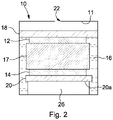
- FIGS. 2 to 4 show an exemplary basic structure of an electrochemical cell. Features in common with the conventional arrangement described above are depicted using like reference numerals. It can be seen that an electrochemical cell 10 comprises a sensing electrode 12, and a counter or counter/reference electrode 14. Although not shown, a separate reference electrode may be provided whereby the electrode 14 then acts purely as a counter electrode.
- Each electrode 12, 14 preferably comprises a very high surface area catalyst 12, 14 supported on a respective gas permeable membrane 18, 20.
- the membrane 18, 20 may be porous PTFE.
- the catalyst 12, 14 may be a metal, such as a finely divided platinum catalyst, or other conductive material e.g. graphite.
- a small amount of PTFE bonding material may be utilized to bond the catalyst 12, 14 to the membrane 18, 20.
- the electrodes 12, 14 are in contact with a liquid electrolyte 16.
- the electrolyte 16 may be an acid, e.g. sulphuric acid.
- the electrolyte may be alkaline or neutral.
- a water electrolyte may be used and even non-aqueous electrolytes can be used in certain cells.
- the electrolyte 16 is typically largely contained within a wick 17 at a condition of lowest humidity.
- the purpose of the wick 17 is to ensure fluid communication between the electrolyte 16 and the electrodes 12, 14.
- the wick 17 may be formed of a glass fibre material. Typically, therefore, the cell components are "stacked".
- On the counter electrode substrate 20 is provided the conductive layer 14, with the wick 17 adjacent thereto.
- the conductive sensing electrode 12 is provided adjacent the wick 17, and on the opposite surface of which is the sensing electrode substrate 18.
- the orientation shown in Figures 2 to 4 is not limitative, and examples can be used in other orientations.
- the examples described above and shown in Figures 2 and 3 comprise two electrodes 12, 14, although a third, reference electrode (not shown) could also be included.
- the counter electrode 14 need not then be used as a combined counter/reference electrode.
- the cell 10 may include more electrodes.
- the cell 10 could comprise four electrodes: two working/sensing electrodes, a counter electrode and a reference electrode. Such cells can be used for the detection of two gases simultaneously.
- the cell 10 comprises a housing in which is provided a diffusion hole 22 through which target gas can enter.
- the housing 10 may be formed of a plastics material, e.g. ABS (acrylonitrile butadiene styrene), carbon-filled ABS, or any other material that is resistant and impermeable to the electrolyte 16.
- the housing forms a reservoir 11 for the electrolyte 16.
- a separate reservoir enclosure may be provided within the housing 10.
- one or more additional sealing and/or filter means 27 (as shown in Figure 3 ) may be provided in or in the vicinity of the diffusion hole 22.
- the filter 27 can filter out any unwanted gases that are not desired to reach the electrode 12 or to permit a gas to be sensed to enter the chamber 11.
- the filter 27 or a sealing member can further assist in containing the electrolyte 16 within the housing/reservoir 11.
- the sensing electrode 12 can also be sealed to the cell body such that electrolyte 16 cannot encroach above the electrode 12.
- the cell 10 and the components thereof may take a variety of forms.
- the PTFE membranes of the electrode substrates 18, 20 may have a thickness of about 140-250 microns.
- Each electrode 12, 14 may be approximately 3mm to 25mm in diameter. In one embodiment, the diameter is approximately 5mm.
- the height of the catalyst layer 12, 14 may typically be between about 10 to 100 • m.
- the thickness of the wick 17 may be between about 0.25mm to 20mm. The thickness is approximately 5mm.
- the electrodes 12, 14, substrates 18, 20, reservoir 11/housing 10 and wick 17 are preferably round/cylindrical (as shown in Figures 3 and 4 ) but may be differently configured.
- a gas source e.g. a cavity 26 is also provided.
- the gas cavity 26 is in fluid communication with the gas inside the cell 10.
- the gas inside the gas cavity 26 will typically be air or comprise constituents similar to air.
- the sensing electrode 12 of the cell 10 will be configured to react with an oxidisable gas, and the counter electrode 14 will be configured to react with oxygen.
- Reference from hereon will thus primarily be directed to examples where the cell 10 is utilised in standard conditions, but it should be appreciated that protection is not limited thereto.
- the gas source/cavity 26 is in fluid communication with the counter electrode 14 and preferably positioned adjacent, e.g. behind or below the counter electrode 14. Electrolyte 16 cannot enter the air cavity 26, although the gas permeable membrane 20 permits oxygen (and other gases) to enter the cavity 26.
- An additional gas permeable/semi-permeable membrane or layer may also be provided to seal the cavity 26, e.g. to allow the electrode 14, 20 and cavity 26 to be constructed separately.
- the cavity 26 therefore prevents the electrolyte 16 in the cell 10 from covering the rear of the counter electrode 14. This prevents oxygen starvation at the counter electrode 14, which could otherwise occur if the electrolyte were to completely cover the rear of the electrode 14 and therefore prevent gas access.
- the sealed nature of the cavity 14 means that the cell 10 is immune to orientation and hydration issues, as will be discussed in greater detail below.
- the gas cavity 26 does not need to cover the whole of the rear 20a of the counter electrode 14, but does need to provide enough "open area” to ensure that oxygen starvation cannot occur. It is preferable to ensure as large an area is provided as possible. In the example of Figure 2 or 3 , the gas cavity 26 covers the majority of the rear 20a of the counter electrode 14, but could alternatively cover the entire rear 20a of the counter electrode 14.
- the volume of the cavity 26 can be chosen so as to provide the amount of oxygen required to ensure the cell 10 continues to operate within expected performance characteristics under extreme conditions.
- the area of the counter electrode surface 20a that the cavity 26 needs to cover depends on the amount of target gas the cell 10 is likely to be required to detect.
- the typical alarm time at 400ppm is 3 minutes.
- the cavity 26 volume/dimensions may also be chosen depending on the desired size and configuration of the cell 10. For example, if the overall height of the cell 10 is desired to be kept to a minimum, a wider, shorter cavity 26 may be provided.
- the cavity 26 is a sealed area between the rear 20a of the counter electrode 14 and the base of the cell housing 10.
- the cavity 26 may be or comprise a hollow, e.g. tubular member or may be a container that is open across one surface thereof.
- the electrode 14, 20 is secured to the cavity 26. If needed, the cavity 26 can be secured to the interior of the housing. Securing of the cavity 26 may be achieved by a number of different means, e.g. by clamping, sealing, welding, gluing or fixing with a gasket.
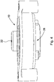
- the cavity 26 does not need to be fixed to the base of the cell body 10, but could be sealed to the rear 20a of the counter electrode 14 as a free standing structure within the cell body 10, as shown in Figure 5 .
- the gas cavity 26 could be formed completely from a gas permeable membrane and therefore be a completely flexible structure.
- the cavity 26 can be formed by an elongate strip of flexible gas permeable material, curved round such that the two free ends thereof meet or are joined together (using any suitable means) to form an annular/tubular structure defining the cavity 26 therein.
- the circumferential surface area can provide a good fluid communication path for replenishing the cavity 26 with oxygen from elsewhere inside the cell 10 after it has been reacted at the counter electrode 14, as discussed further below.
- oxygen gas needs to enter the counter electrode 14 by passing through the permeable membrane 20. For this to occur, at least a portion of the rear surface 20a of the counter electrode 14 needs to be "dry", i.e. free from electrolyte. Otherwise, the electrolyte 16 would prevent oxygen gas passing into the membrane 14 and to the counter electrode 14.
- Dryness of at least part of the rear surface 20a of the counter electrode 14 is achieved through the provision of the adjacent gas source or cavity 26 providing a necessary source of oxygen.
- the gas cavity 26 must be replenished with oxygen in order for the cell 10 to continue to operate effectively.
- the cavity 26 is sealed from the environment outside of the cell 10, and so the oxygen can only be replenished from inside the cell 10. Since it is undesirable for electrolyte 16 to enter the cavity 26, the cavity 26 may be or comprise a semi-permeable membrane, as previously mentioned. In most practical embodiments, the gas outside of the cell 10 is air.
- the cavity/membrane 26 is in fluid contact with the gas that is inside the cell 10, and the cell 10 is in fluid contact with air external to the cell 10 via the diffusion hole 22.
- the gas inside the cavity 26 will also be air (or a gas that is related to/ resembles air, since the semi-permeable membrane may cause a slight difference in the actual composition of gases within the cell).
- a potential problem can arise if there is any free electrolyte 16 in the cell 10 (i.e. not contained within the wick) because, depending on the orientation of the cell, this free acid 16 could cover the rear 20a of the counter electrode 14 if there was no sealed cavity 26 in place. In the arrangement of Figure 2 or 3 , this could occur when the cell 10 is oriented with the diffusion hole 22 upwards. Other configurations are known, but these also suffer from the same effects. For example, cells are known in which the working and counter electrodes are provided on a single planar substrate. Cells of this kind suffer the same fate if the cell is oriented with the diffusion hole downwards. In addition, if the electrode 14, 20 is placed directly against a solid surface, e.g. the cell housing 10, this could also prevent gas entering the rear of the electrode 20, so it is beneficial for the electrode 14, 20 to be spaced from the cell housing 10.
- orientation can have a dramatic effect on cell performance under certain circumstances.
- orientation of any detector cannot be guaranteed, then this represents a performance risk for these cells.
- Figure 6 which demonstrates the issues that arise for a known cell that does not include a cavity 26 adjacent the counter electrode 14.
- Figure 6(a) shows the "fully hydrated" situation, where electrolyte 16 fully covers the rear of the counter electrode 14. Although there will be a small amount of air/oxygen dissolved in the electrolyte, this is unlikely to be a sufficient oxygen source for the counter electrode under a "high use” where a large amount of target gas is being sensed. The electrolyte 16, therefore, prevents air that would otherwise be able to reach the counter electrode 14 from doing so.
- the known cell comprises an additional wick 17' that still provides a path for electrolyte 16 to the sensing electrode 12 even in a minimum hydration condition such as that shown in Figure 6(b) .
- the additional wick 17' comprises a portion that sits between the main wick 17 and the counter electrode 14.
- Embodiments of the present invention could also be provided with an additional wick.
- Figure 6(b) illustrates the situation where there is minimum hydration in the cell 10.
- the rear 20a of the electrode 14 is dry and a maximum volume of air/oxygen is available to feed to the counter electrode 15 as air/oxygen is readily available within the cell and at the counter electrode 14.
- Figure 6(c) illustrates the scenario where the cell 10 is inverted, as may well be required in some sensing locations. Even though there is a low volume of electrolyte 16 (as in Figure 6(b) , it still covers the rear 20a of the counter electrode 14 and thus prevents oxygen access through the semi-permeable membrane 20.
- the electrolyte 16 in the cell 10 is in dynamic equilibrium with the environment and will typically be hygroscopic. This means that the electrolyte 16 will absorb or lose water (slowly) depending on the external atmospheric humidity via the diffusion hole 22 in the cell 10. Under high humidity conditions, the electrolyte 16 will absorb water and, as a result, the volume of the electrolyte 16 will increase. For example, for a cell 10 designed to operate between 15% and 90% rH (relative humidity), this can equate to a change in electrolyte volume of over 400% between these extreme conditions. Therefore, when the cell 10 is placed in a high humidity environment for a long period of time, the chance of the electrolyte 16 covering the rear 20a of the counter electrode 14, and therefore preventing oxygen reaching the electrode 14, increases dramatically.
- an air cavity 26 adjacent the rear 20a of the counter electrode 14 prevents the electrolyte 16 from covering the rear 20a of the counter electrode 14, and thus prevents a drop in performance that may otherwise occur.
- a further factor that can affect cell performance is long exposure of the cell 10 to high concentrations of the target gas.
- the quantity of oxygen reaching the counter electrode 14 is sufficient to ensure that the cell 10 is producing a current that is directly related to the concentration of gas reaching the working electrode 12.
- the amount of oxygen required at the counter electrode 14 exceeds the amount of oxygen that can reach the counter electrode 14 through the counter membrane 20.
- the current output from the cell 10 decreases.
- the cell 10 recovers. This can, however, take a finite time depending on how long it takes for the oxygen environment around the counter electrode 14 to return to its ambient conditions.
- an air cavity 26 on the rear 20a of the counter electrode 14 provides a larger source of oxygen for the counter electrode 14 such that a situation of oxygen starvation is only reached under very extreme conditions.
- the cell 10 is thus able to operate with good, consistent performance over a wider range of conditions than a cell that does not have an air cavity.
- the counter electrode 14 can be completely covered with electrolyte 16 and thence oxygen starvation can occur even under normal operating conditions.
- the electrolyte 16 is in equilibrium with gas outside the cell, excluding any oxidisable gases that will be consumed at the sensing electrode. Hence, as mentioned previously, air will be dissolved (in small amounts) in electrolyte 16.
- the cavity 26 is an impermeable structure fixed to the rear 20a of the counter electrode 14. Since the electrode membrane 20 is semi-permeable, liquid cannot permeate therethrough into the cavity 26, but gas such as gases including oxygen can. Gas, e.g. oxygen, enters the cavity 26 having permeated through the semi-permeable membrane 20, and is therefore in equilibrium with gas/oxygen in the liquid electrolyte 16. Since the electrolyte 16 has air/oxygen dissolved in it, this air/oxygen will pass into the cavity 26 until an equilibrium position is achieved.
- air and a target gas enters the cell 10 through the diffusion hole 22.
- the sensing electrode 12 reacts with any oxidisable gases and converts them to a fully oxidised form (e.g. CO ⁇ CO2). Air with any oxidised gases will dissolve in small amounts in the electrolyte 16 and also enter any areas inside the cell 10 that is not full of electrolyte 16. Any gases dissolved in the electrolyte 16 will slowly permeate through the semi-permeable membrane 20 and the gas composition in the cavity 26 will equalise with the external gas composition, minus any oxidisable gases.
- the air cavity 26 will always provide a ready source of oxygen for the reaction that occurs at the counter electrode 14. Under conditions of high use (e.g. 400ppm for 4 hours), the gas cavity 26 provides a large source of oxygen - far higher than could be provided from the electrolyte 16 alone.
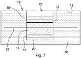
- the reservoir 11 of electrolyte 16 extends primarily around the main wick 17 and not above or below it.
- the reservoir 11 does not extend above or below the (upper and lower) ends of the main wick 17 and the majority of the electrolyte 16 is located transversely around the axial wick 17.
- the reservoir 11 extends primarily around the stack formed by the electrodes 12, 14 and main wick 17, rather than above or below the stack 12, 14, 17. That is to say, the majority of the electrolyte 16 and reservoir 11 is provided peripherally, laterally, radially or circumferentially around the wick 17 or the stack.
- the majority of the electrolyte 16 is thus provided around the wick 17 or the stack 12, 14, 17, encircling it. This is in contrast to known prior art arrangements, in which the electrolyte/reservoir is provided between or below the electrodes. NB.
- the electrolyte 16 cannot surround the working/sensing electrode 12 completely since gas could not then access the electrode 12 and the cell 10 would not be workable.
- the electrolyte 16 may, however, partially surround or extend peripherally around the sensing electrode 12.
- the example of Figure 7 is shown with the reservoir 11 surrounding the entire stack, but with the area above the sensing electrode 12 devoid of electrolyte 16. Alternatively, this area could be increased or decreased, or the electrolyte 16 could surround less of the stack, e.g.
- the electrolyte 16 may only partially surround the counter electrode 14.
- the cell 10 further comprises an additional or secondary wick 28, to ensure electrolyte 16 in the reservoir 11 is available to the main wick 17 and thus to the electrodes 12, 14.
- the additional wick 28 extends transversely to the direction of the stack 12, 14, 17.
- the additional wick is annular.
- the additional wick (28) sits around the main wick 17.
- the additional wick 28 could be differently shaped, e.g. be square, rectangular, or oval etc. in shape, and have a regular or irregular form.
- a circumferential reservoir 11 advantageously enables the main wick 17 to remain short.
- This arrangement allows the distance between the two electrodes 12, 14 to be kept relatively small, which overcomes the issue of high internal resistance described above, whilst achieving an effective electrolyte communication path between the reservoir and the wick 17.
- this arrangement permits a relatively large reservoir to be created for only a relatively small increase in radius.
- the arrangement of the reservoir 11 surrounding the wick 17 means that electrolyte 16 can enter the wick 17 from all sides therefore making exchange of electrolyte 16 to the wick 17 from the reservoir 11 more effective.
- the reservoir 11 being an annulus around the wick 17, means that the cell 10 is completely immune from orientation effects, as opposed to the other known designs where certain orientations mean that communication of electrolyte from the reservoir into the wick is more difficult.
- the cell 10 of aspects and embodiments of the present invention may be operated in amperometric mode using a high impedance op-amp circuit, as is known in the art, and as will be discussed in relation to Figure 8 below.
- the electrochemical cells 10 of embodiments of the invention described above can be utilised, inter alia, in gas detectors.
- a wide range of target gases can be detected including, oxidisable gases such as, but not limited to, ammonia, carbon monoxide (CO), diborane, fluorine, hydrazine, hydrogen (H 2 ), hydrogen cyanide, hydrogen fluoride, hydrogen selenide, hydrogen sulphide (H 2 S), hydrogen chloride (HCI), hydrogen bromide (HBr), arsine (AsH 3 ), mercaptan, nitric oxide, phosgene, phosphene (PH 3 ), silane, sulphur dioxide (SO 2 ), or chlorine (Cl 2 ).
- reducible gases such as chlorine dioxide, ethylene oxide, nitrogen dioxide, oxygen, and ozone.
- CO detectors are designed to measure CO levels over time and raise an alarm before a predetermined level is reached. Detectors of this kind are particularly useful since CO is either difficult or impossible to detect without specialised detection equipment and is potentially dangerous, sometimes fatal, to humans. From a practical point of view as discussed above, embodiments of the invention can be incorporated into any cell that works on the principle of oxygen consumption at the counter electrode.
- An electrochemical cell 10 can be utilised in a gas detector, e.g. a CO detector. During operation, the current produced by the cell 10 is related to the concentration of CO (or other gas) in the atmosphere.
- electrochemical cells 10 of embodiments of the present invention can be incorporated into gas (e.g. CO) detectors in place of existing electrochemical cells in a conventional way without any modifications.
- the cell 10 can be configured to be matched to the target concentration of gas to be detected.
- the cell 10 may comprise a chemical filter 27 (visible in Figure 3 ), for filtering out unwanted gases. This enables a specifically located cell 10 to reliably detect the target gas.
- Embodiments of aspects of the present invention are capable of, and designed to be exposed to, any concentration of gases, including those that are higher than normally experienced.
- the cell may be configured to detect less than 10,000ppm of the target gas, and preferably lower than 1,000ppm, which is the level at which CO becomes poisonous to humans for short exposure times, but is not limited to this.
- Figure 8 shows an exemplary control circuit 30 that may be employed in a CO detector incorporating the two- (or three-) electrode cell 10.
- the circuit 30 is a simple potentiostat circuit for driving the cell 10, as would be understood by those skilled in the art.
- the cell 10 is shown on the left hand side of Figure 8 , from which it can be seen that the working (sensing) and counter electrodes 12, 14 are connected to the circuit 30.
- the electrochemical cell 10 will produce a current when exposed to the target gas, and this current is directly related to the concentration of gas the cell is exposed to.
- This current flows through a resistor 32, generating a small voltage difference across the cell 10.
- An operational amplifier (op-amp) 34 is provided to regulate the electrode 12, 14 potentials and ensure the sensor 30 can operate at maximum efficiency. Any op-amp having low input offset voltages meaning the cell electrodes are not biased can be utilized.
- the op-amp 34 provides a feedback voltage to the working electrode to balance the small voltage generated across the cell 10. The voltage generated, V out , is therefore directly related to the current flowing through the cell 10 and therefore directly related to the concentration of target gas the cell 10 is exposed to.
- Two resistors 36, 38 control the gain of the op-amp 34.
- a thermistor 40 can optionally be provided to compensate for temperature effects in the cell 10 and circuit 30.
- Capacitors 42, 44 are provided for reducing noise in the circuit 30.
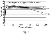
- Figure 9 illustrates the effect that the provision of a gas cavity 26 has on performance of the cell 10.
- the graph shows results of placing cells in a test chamber and exposing them to 400ppm CO (400 parts per million of Carbon Monoxide) for four hours.
- the graph shows the current output in microamps on the vertical axis and the elapsed time in minutes on the horizontal axis.
- the current generated is directly proportional to the gas concentration.
- the current output for an ideal detector would thus be a horizontal line on the graph of Figure 9 .
- Plot A is a control result showing the output from a cell with no gas cavity 26.
- the five plots labelled B are results from cells according to the present invention with gas cavities 26 of different sizes, ranging from 1mm to 4mm.
- the gas in the cavity 26 initially was air although, as explained above, the composition of the gas within the cavity 26 can change slightly over time. It should be noted that the cells providing the results for the 'B' plots were designed to provide an alarm at 400ppm CO within 3 minutes.
- the size of the cell used did not have a significant effect on the performance of the cell.
- the provision of a gas cavity e.g. an air gap of any size vastly improved the performance of the cell over cells having no gas cavity or air gap.
- a gas detector can comprise an electrochemical cell having such a combination of features.
Description
- The present invention relates to an electrochemical cell for use in a gas detector as defined in
claim 1. Details of the electrochemical cell are defined in dependent claims 2-10 and a gas detector comprising the electrochemical cell is defined inclaim 11. - Amperometric electrochemical cells have found widespread use for the detection of various gases in the environment, including use for the detection of carbon monoxide in the domestic environment.
- As shown in
Figure 1 , atypical cell 10 comprises two or three gas electrodes - a working or sensingelectrode 12, acounter electrode 14 and, optionally, a reference electrode (not shown). In lower cost cells, the reference electrode is often omitted and the counter electrode serves as a combined counter/reference electrode. All three (two) of these electrodes comprise a very high surface area catalytic metal (or other conductive material) 12, 14 supported on a gas permeable membrane orsubstrate electrolyte 16, for example an acid, is typically completely contained within awick 17 at a condition of lowest humidity. Thewick 17 acts to hold and supply electrolyte to thesensing electrode 12 such that the chemical reaction discussed below can occur. Thecell 10 comprises a housing that defines areservoir 11 for theelectrolyte 16, in which is provided adiffusion hole 22 through which target gas can enter. - The basic principle of operation is that gas enters the
cell 10 via thediffusion hole 22. The gas passes through the gaspermeable membrane 18 of thesensing electrode 12 and contacts thecatalyst 12. A reaction occurs at the interface of thecatalyst 12 and the acid electrolyte 16 (i.e. at the intersection of gas, liquid and solid). This reaction releases or consumes a number of electrons (the precise number depending on the gas being sensed) that are supplied via anexternal circuit 24. - For example, in a cell configured to sense carbon monoxide (CO), the gas is oxidised at the surface of the
sensing electrode 12 to produce positive hydrogen ions (H+) and negative electrons (e-):
2CO + 2H2O• 2CO2 + 4H+ + 4e-
- The positive ions travel through the
electrolyte 16 to thecounter electrode 14, and the negatively charged electrons travel to thecounter electrode 14 via thecircuit 24. The reaction is completed at the counter electrode 14:
4H+ + 4e- + O2• 2H2O
- The overall reaction is:
2CO + O2 • 2CO2
- The working
electrode 12 is arranged such that gas from the environment enters thecell 10 and permeates through thesubstrate 18 where the 'target gas' present in the environmental gas (i.e. the gas that is to be sensed) reacts completely. Each gas molecule that reacts at thesubstrate 18 produces a fixed number of electrons (the number depending on the gas reacting) and the measurement of the current produced can then be related to the number of molecules of gas that has entered the cell and this is directly proportional to the concentration of the target gas in the environment. An ammeter, voltmeter orother circuit 24 can be used to measure/derive the current produced. - The counter and reference electrodes are, however, different. For measurement of a target gas in air, the counter/
reference electrode 14 is generally configured to react with oxygen. This oxygen needs to contact themetal catalyst 14 at the interface of gas, liquid (electrolyte) and solid (catalyst). In theory, this oxygen could come from one of two places: either from air inside thecell 10 or from oxygen gas dissolved in theelectrolyte 16. However, the solubility of oxygen in theelectrolyte 16 is very low and the concentration of oxygen in air inside thecell 10 is relatively high and therefore oxygen from inside thecell 10 is consumed at the counter/reference electrode 14. This oxygen has to reach the metal/electrolyte interface permeable membrane 20 in order to reach the solid/liquid interface as previously described. - There are various factors that affect the efficient and reliable working and performance of an electrochemical cell.
- Under certain conditions, or combinations of conditions, a degree of oxygen starvation can occur at the
counter electrode 14 resulting in a decrease of the electrochemical efficiency due to the development of bias voltages. This results in a reduction of the current expected for a known concentration of the target gas, in turn resulting in an erroneous (low) reading of the gas concentration. These conditions include the orientation of the cell, the degree of hydration of theelectrolyte 16 and high concentrations of the target gas for long exposure times. Furthermore, combinations of these conditions can increase the tendency for non-ideal performance, which is undesirable as it can lead to erroneous gas concentration measurements. - Acid electrolyte is generally hygroscopic in nature. That is, it will absorb or desorb water from the environment until the strength of the
acid 16 is in equilibrium with the external atmospheric humidity. This absorption or desorption of water is accompanied with a change in the volume of theacid electrolyte 16. For the typical acid electrolyte used in these cells, sulphuric acid, the volume change from the typical lower operating humidity (15%) to the typical upper operating humidity (90%) can be as much as a factor of four. Therefore the design of the electrochemical cell has to be such that, at the highest operating humidity, thecell 10 is not so full that it leaks or bursts whilst, at the lowest humidity, the volume has to be large enough to ensure that the surfaces of both electrodes are fully wetted and that there is a continuous fluid path between the two electrodes (via the wick material). - Known cells all effectively comprise an axial reservoir, located either between or below the electrodes to accommodate the expansion in the electrolyte volume.
- For reservoirs that are between the
electrodes electrodes - For reservoirs that are below the
lower electrode 14, there is sometimes the need for an additional thin piece of wick (or other wicking mechanism) to ensure that free acid is transferred into the 'main'wick 17. However, this wicking does not always occur effectively and can result in issues with repeated hydration/dehydration cycles. This is amplified by the fact that this thin piece of wick needs to be relatively long. Furthermore, positioning of this material during manufacture is complex and not easily amenable to automation. - In addition, the need for the axial reservoir imposes a certain physical structure on the cell and determines the height of the cell as approximately a minimum of 20mm. For domestic carbon monoxide detectors, this height constricts the possible design options available for the detector. Aspects and embodiments of the present invention have been designed with one or more of the foregoing in mind.
-
WO 2005/085824A1 discloses an electrochemical gas sensor comprising: a working electrode comprising a gas porous membrane and a catalyst layer formed on one side of the membrane; a counter electrode comprising a catalyst; electrolyte in contact with the catalyst both of the working electrode and of the counter electrode; and a support that is in contact with, and presses down on, the side of the working electrode remote from the electrolyte and that compresses the electrodes and the electrolyte together. -
WO 2010/063626A1 discloses an electrochemical gas sensor including an ionic liquid as electrolyte. -
US5372696A discloses an electrochemical sensor for fluid media with at least two electrodes, which are in contact with one another via an electrolyte and are accommodated in a housing.US 2011/290671A1 discloses an electrochemical gas sensor for detecting hydrocyanic acid in a gas sample has a measuring electrode formed of carbon nanotubes (CNT) and a counterelectrode in an electrolyte, which contains lithium bromide in an aqueous solution. -
WO 2004/031758A1 discloses an electrochemical oxygen sensor comprises a sensing electrode and a consumable counter electrode, a porous separator between the electrodes, and liquid electrolyte absorbed in the separator, all mounted in a housing. -
US7077938B1 discloses an electrochemical gas sensor. -
US4824551A discloses a method for measuring the amount of an electroactive gas in a gaseous mixture using an electrochemical cell. -
WO2015124276A1 discloses an electrochemical gas sensor. - There is provided an electrochemical cell according to
claim 1 and a gas detector according toclaim 11. - The electrochemical cell can, in principle, be used for detecting any gas, e.g. oxidisable and reducible gases. However, the electrochemical cell is most likely to be utilized in a location of standard environmental conditions, i.e. for sensing a target gas in air in the vicinity of the cell. As such, the electrochemical cell of embodiments of the present invention is particularly suited to detecting oxidisable gases, which will then require the source of reactant gas adjacent to the counter or counter/reference electrode to be a source of oxygen. The source of reactant gas adjacent to the counter or counter/reference electrode may thus be or closely resemble air. The reactant gas e.g. oxygen may be replenished by diffusion from the main cell body when the cell is idle (i.e. not detecting).
- Preferably, the source of reactant gas is a gas cavity provided adjacent the counter electrode. The gas cavity may be dimensioned so as to at least partially or totally cover the counter electrode. The gas cavity is preferably dimensioned so as to provide at least a sufficient source of reactant gas to the counter electrode. Preferably, the gas cavity is sealed from the gas atmosphere outside the cell. This is because, for the reference electrode to perform well, none of the target gas must reach the reference/counter electrode. The volume of gas provided within the gas cavity may be predetermined.
- The sensing electrode, counter electrode and gas cavity may be provided in a housing. Preferably, the housing is impermeable to and/or sealed from the gas atmosphere outside of the cell, apart from an inlet provided for detecting the target gas. In an example, the gas cavity is provided between the counter electrode and the housing. The gas cavity may be fixed to the housing and/or sealed to the counter electrode. The gas cavity may be a flexible structure. The gas cavity may be formed by the use of a gas permeable or semi-permeable membrane that is in fluid communication with the interior of the cell. Typically, the counter electrode is mounted on a membrane or substrate. This may be the same gas permeable or semi-permeable membrane, or may be an additional membrane. In an example, the gas cavity communicates gas from within the cavity with gas inside the cell. The gas cavity is preferably impermeable to the electrolyte and permeable to gases.
- The electrochemical cell further comprises a wick. The sensing electrode, wick, counter electrode and gas cavity are preferably axially aligned with respect to each other. The sensing electrode, wick, counter electrode and gas cavity may form a stack.
- The counter electrode may act as a combined counter/reference electrode. The electrochemical cell may further comprise one or more additional electrodes. In an embodiment, a third or reference electrode is provided. In other embodiments, a fourth electrode that is a second sensing or working electrode may be provided.
- An effect of utilizing the gas source or cavity in examples is that the "free" surface of the counter electrode, i.e. that distal from the wick, is kept free from electrolyte. This enables an increased supply of oxygen to the counter electrode than would otherwise be possible. Examples thus advantageously avoid oxygen starvation at the counter electrode and thus maximise the electrochemical efficiency of the cell. In such embodiments, performance is maintained irrespective of the orientation of the cell, leading to the cell being able to be used in a wider variety of installations and places.
- According to the present invention, there is provided an electrochemical cell as defined in
claim 1. The electrochemical cell can, advantageously, be used for detecting any gas, e.g. oxidisable and reducible gases. - In contrast to known prior art arrangements, where the cell comprises an axial reservoir, located either between or below the electrodes, the reservoir of the present invention surrounds the wick and does not extend above or below the wick in an axial direction. In such an arrangement, the majority of the electrolyte in the reservoir is provided around the wick, peripherally, laterally, radially or circumferentially. This advantageously aids absorption of electrolyte by the wick, and thus transport of electrolyte to the electrodes.
- The reservoir extends primarily in a direction transverse to the wick. More preferably, the reservoir is an annular reservoir that surrounds the wick.
- Preferably, the sensing electrode, wick and counter electrode are arranged axially with respect to each other to form a stack. The reservoir extends primarily in a direction transverse to the stack. The reservoir preferably surrounds or at least partially surrounds the stack.
- A secondary wick is also provided, which extends transversely to the wick. The secondary wick comprises a thin planar element. The secondary wick may be annular.
- The sensing electrode, counter electrode and wick are preferably provided in a housing, the housing forming the reservoir. Alternatively, a separate reservoir may be provided inside the housing.
- The counter electrode may act as a combined counter/reference electrode. The electrochemical cell may further comprise one or more additional electrodes. The electrochemical cell may comprise a third or reference electrode. In an embodiment, the cell further comprises one or more additional second sensing or working electrodes.
- Embodiments of the invention avoid the need to place a reservoir between electrodes, which advantageously avoids the high internal resistance which can otherwise occur between the electrodes. The provision of a reservoir and thus the electrolyte substantially transverse to the axially arranged electrodes advantageously enables the distance between the two electrodes to be kept to a minimum which, in turn reduces the overall height of the cell, which clearly increases the utility of cells of embodiments of the invention. The arrangement of the reservoir transversely around the wick means that electrolyte can enter the wick from all sides, advantageously increasing the effective electrolyte communication path between the reservoir and the wick. This arrangement also means that the cell is completely immune from orientation effects.
- In principle, the gas detector may be configured for detecting one or more oxidisable or reducible gases. In a preferred embodiment, the gas detector is configured for detecting one or more oxidisable gases. The gas detector may particularly be configured for detecting one or more of: ammonia, carbon monoxide, chlorine, diborane, fluorine, hydrazine, hydrogen, hydrogen cyanide, hydrogen fluoride, hydrogen selenide, hydrogen sulphide, hydrogen chloride, hydrogen bromide, arsine, mercaptan, nitric oxide, phosgene, phosphene, silane, or sulphur dioxide. These gases are provided by way of example only, and embodiments of the invention are not limited to the detection of these gases.
- As mentioned above, in principle, embodiments of the invention can also be utilised to detect a reducible gas. In such embodiments, the reactant gas may be or contain hydrogen. In such embodiments it may be difficult to replenish the reactant gas from gas inside the cell and it may then necessary to provide an additional reactant gas replenishing source.
- The embodiments of the invention described above may be utilised in any combination within the same electrochemical cell and/or gas detector. For example, an electrochemical cell may comprise the features of both of the related aspect and the first aspect, and optionally any or all of the claims dependent thereon. Such a cell may be utilised in a gas detector according to embodiments of the invention.
- Embodiments of the invention will now be described with reference to the following drawings, in which:
-
Figure 2 is a schematic cross sectional view of an electrochemical cell according to an example useful for understanding the invention; -
Figure 3 is a perspective cross sectional view of an electrochemical cell; -
Figure 4 is a front perspective view of an electrochemical cell; -
Figure 5 is a schematic cross sectional view of an electrochemical cell according to an example useful for understanding the invention; -
Figures 6(a) to (c) are schematic cross sectional views illustrating a known electrochemical cell in various hydration and orientation conditions that is useful for understanding the invention; -
Figure 7 is a schematic cross sectional view of an electrochemical cell; -
Figure 8 is an exemplary control circuit for a carbon monoxide detector incorporating an electrochemical cell; and -
Figure 9 illustrates performance results obtained using cells of embodiments of the invention compared with a reference. -
Figures 2 to 4 show an exemplary basic structure of an electrochemical cell. Features in common with the conventional arrangement described above are depicted using like reference numerals. It can be seen that anelectrochemical cell 10 comprises asensing electrode 12, and a counter or counter/reference electrode 14. Although not shown, a separate reference electrode may be provided whereby theelectrode 14 then acts purely as a counter electrode. - Each
electrode surface area catalyst permeable membrane membrane catalyst catalyst membrane - The
electrodes liquid electrolyte 16. Theelectrolyte 16 may be an acid, e.g. sulphuric acid. The electrolyte may be alkaline or neutral. A water electrolyte may be used and even non-aqueous electrolytes can be used in certain cells. Theelectrolyte 16 is typically largely contained within awick 17 at a condition of lowest humidity. The purpose of thewick 17 is to ensure fluid communication between theelectrolyte 16 and theelectrodes wick 17 may be formed of a glass fibre material. Typically, therefore, the cell components are "stacked". On thecounter electrode substrate 20 is provided theconductive layer 14, with thewick 17 adjacent thereto. Theconductive sensing electrode 12 is provided adjacent thewick 17, and on the opposite surface of which is thesensing electrode substrate 18. The orientation shown inFigures 2 to 4 , with the components arranged vertically and with thecounter electrode 14 lowermost, is not limitative, and examples can be used in other orientations. - The examples described above and shown in
Figures 2 and3 comprise twoelectrodes counter electrode 14 need not then be used as a combined counter/reference electrode. In other examples, also not shown in the Figures, thecell 10 may include more electrodes. For example, thecell 10 could comprise four electrodes: two working/sensing electrodes, a counter electrode and a reference electrode. Such cells can be used for the detection of two gases simultaneously. - The
cell 10 comprises a housing in which is provided adiffusion hole 22 through which target gas can enter. Thehousing 10 may be formed of a plastics material, e.g. ABS (acrylonitrile butadiene styrene), carbon-filled ABS, or any other material that is resistant and impermeable to theelectrolyte 16. The housing forms areservoir 11 for theelectrolyte 16. Alternatively, a separate reservoir enclosure may be provided within thehousing 10. In either case, one or more additional sealing and/or filter means 27 (as shown inFigure 3 ) may be provided in or in the vicinity of thediffusion hole 22. The filter 27 can filter out any unwanted gases that are not desired to reach theelectrode 12 or to permit a gas to be sensed to enter thechamber 11. The filter 27 or a sealing member can further assist in containing theelectrolyte 16 within the housing/reservoir 11. Thesensing electrode 12 can also be sealed to the cell body such thatelectrolyte 16 cannot encroach above theelectrode 12. - The
cell 10 and the components thereof may take a variety of forms. The PTFE membranes of theelectrode substrates electrode catalyst layer wick 17 may be between about 0.25mm to 20mm. The thickness is approximately 5mm. - The
electrodes substrates reservoir 11/housing 10 andwick 17 are preferably round/cylindrical (as shown inFigures 3 and4 ) but may be differently configured. - In the examples of
Figures 2-5 a gas source, e.g. acavity 26 is also provided. In the example shown thegas cavity 26 is in fluid communication with the gas inside thecell 10. Examples may most usefully be employed in standard atmospheric conditions, i.e. where thecell 10 is surrounded by air. As such, the gas inside thegas cavity 26 will typically be air or comprise constituents similar to air. When used in such standard conditions, thesensing electrode 12 of thecell 10 will be configured to react with an oxidisable gas, and thecounter electrode 14 will be configured to react with oxygen. Reference from hereon will thus primarily be directed to examples where thecell 10 is utilised in standard conditions, but it should be appreciated that protection is not limited thereto. - The gas source/
cavity 26 is in fluid communication with thecounter electrode 14 and preferably positioned adjacent, e.g. behind or below thecounter electrode 14.Electrolyte 16 cannot enter theair cavity 26, although the gaspermeable membrane 20 permits oxygen (and other gases) to enter thecavity 26. An additional gas permeable/semi-permeable membrane or layer (not shown) may also be provided to seal thecavity 26, e.g. to allow theelectrode cavity 26 to be constructed separately. Thecavity 26 therefore prevents theelectrolyte 16 in thecell 10 from covering the rear of thecounter electrode 14. This prevents oxygen starvation at thecounter electrode 14, which could otherwise occur if the electrolyte were to completely cover the rear of theelectrode 14 and therefore prevent gas access. The sealed nature of thecavity 14 means that thecell 10 is immune to orientation and hydration issues, as will be discussed in greater detail below. - The
gas cavity 26 does not need to cover the whole of the rear 20a of thecounter electrode 14, but does need to provide enough "open area" to ensure that oxygen starvation cannot occur. It is preferable to ensure as large an area is provided as possible. In the example ofFigure 2 or3 , thegas cavity 26 covers the majority of the rear 20a of thecounter electrode 14, but could alternatively cover the entire rear 20a of thecounter electrode 14. The volume of thecavity 26 can be chosen so as to provide the amount of oxygen required to ensure thecell 10 continues to operate within expected performance characteristics under extreme conditions. The area of thecounter electrode surface 20a that thecavity 26 needs to cover depends on the amount of target gas thecell 10 is likely to be required to detect. By way of an example, for aCO cell 10 in a domestic environment, the typical alarm time at 400ppm (parts per million) is 3 minutes. Acavity 26 having a depth of about 1mm, but covering the majority of the electrode area, ensures that at 400ppm for 4 hours, less than 10% of the available oxygen in thecavity 26 is consumed. Thecavity 26 volume/dimensions may also be chosen depending on the desired size and configuration of thecell 10. For example, if the overall height of thecell 10 is desired to be kept to a minimum, a wider,shorter cavity 26 may be provided. - In the example of
Figure 2 or3 , thecavity 26 is a sealed area between the rear 20a of thecounter electrode 14 and the base of thecell housing 10. Thecavity 26 may be or comprise a hollow, e.g. tubular member or may be a container that is open across one surface thereof. Theelectrode cavity 26. If needed, thecavity 26 can be secured to the interior of the housing. Securing of thecavity 26 may be achieved by a number of different means, e.g. by clamping, sealing, welding, gluing or fixing with a gasket. Thecavity 26 does not need to be fixed to the base of thecell body 10, but could be sealed to the rear 20a of thecounter electrode 14 as a free standing structure within thecell body 10, as shown inFigure 5 . Alternatively, although not shown in the Figures, thegas cavity 26 could be formed completely from a gas permeable membrane and therefore be a completely flexible structure. In an example, thecavity 26 can be formed by an elongate strip of flexible gas permeable material, curved round such that the two free ends thereof meet or are joined together (using any suitable means) to form an annular/tubular structure defining thecavity 26 therein. The circumferential surface area can provide a good fluid communication path for replenishing thecavity 26 with oxygen from elsewhere inside thecell 10 after it has been reacted at thecounter electrode 14, as discussed further below. - In order for the
counter electrode 14 to operate effectively, oxygen gas needs to enter thecounter electrode 14 by passing through thepermeable membrane 20. For this to occur, at least a portion of therear surface 20a of thecounter electrode 14 needs to be "dry", i.e. free from electrolyte. Otherwise, theelectrolyte 16 would prevent oxygen gas passing into themembrane 14 and to thecounter electrode 14. - Dryness of at least part of the
rear surface 20a of thecounter electrode 14 is achieved through the provision of the adjacent gas source orcavity 26 providing a necessary source of oxygen. As oxygen in thecavity 26 is consumed when thecell 10 is detecting gas, as described above, thegas cavity 26 must be replenished with oxygen in order for thecell 10 to continue to operate effectively. Thecavity 26 is sealed from the environment outside of thecell 10, and so the oxygen can only be replenished from inside thecell 10. Since it is undesirable forelectrolyte 16 to enter thecavity 26, thecavity 26 may be or comprise a semi-permeable membrane, as previously mentioned. In most practical embodiments, the gas outside of thecell 10 is air. The cavity/membrane 26 is in fluid contact with the gas that is inside thecell 10, and thecell 10 is in fluid contact with air external to thecell 10 via thediffusion hole 22. As such, the gas inside thecavity 26 will also be air (or a gas that is related to/ resembles air, since the semi-permeable membrane may cause a slight difference in the actual composition of gases within the cell). - A potential problem can arise if there is any
free electrolyte 16 in the cell 10 (i.e. not contained within the wick) because, depending on the orientation of the cell, thisfree acid 16 could cover the rear 20a of thecounter electrode 14 if there was no sealedcavity 26 in place. In the arrangement ofFigure 2 or3 , this could occur when thecell 10 is oriented with thediffusion hole 22 upwards. Other configurations are known, but these also suffer from the same effects. For example, cells are known in which the working and counter electrodes are provided on a single planar substrate. Cells of this kind suffer the same fate if the cell is oriented with the diffusion hole downwards. In addition, if theelectrode cell housing 10, this could also prevent gas entering the rear of theelectrode 20, so it is beneficial for theelectrode cell housing 10. - Therefore, for electrochemical cells, orientation can have a dramatic effect on cell performance under certain circumstances. However, as the orientation of any detector (containing a cell) cannot be guaranteed, then this represents a performance risk for these cells.
- This is illustrated in
Figure 6 , which demonstrates the issues that arise for a known cell that does not include acavity 26 adjacent thecounter electrode 14.Figure 6(a) shows the "fully hydrated" situation, whereelectrolyte 16 fully covers the rear of thecounter electrode 14. Although there will be a small amount of air/oxygen dissolved in the electrolyte, this is unlikely to be a sufficient oxygen source for the counter electrode under a "high use" where a large amount of target gas is being sensed. Theelectrolyte 16, therefore, prevents air that would otherwise be able to reach thecounter electrode 14 from doing so. The known cell comprises an additional wick 17' that still provides a path forelectrolyte 16 to thesensing electrode 12 even in a minimum hydration condition such as that shown inFigure 6(b) . The additional wick 17' comprises a portion that sits between themain wick 17 and thecounter electrode 14. Embodiments of the present invention could also be provided with an additional wick. -
Figure 6(b) illustrates the situation where there is minimum hydration in thecell 10. Here, the rear 20a of theelectrode 14 is dry and a maximum volume of air/oxygen is available to feed to the counter electrode 15 as air/oxygen is readily available within the cell and at thecounter electrode 14. -
Figure 6(c) illustrates the scenario where thecell 10 is inverted, as may well be required in some sensing locations. Even though there is a low volume of electrolyte 16 (as inFigure 6(b) , it still covers the rear 20a of thecounter electrode 14 and thus prevents oxygen access through thesemi-permeable membrane 20. - Another factor that can affect the performance of a cell is the degree of electrolyte hydration. The
electrolyte 16 in thecell 10 is in dynamic equilibrium with the environment and will typically be hygroscopic. This means that theelectrolyte 16 will absorb or lose water (slowly) depending on the external atmospheric humidity via thediffusion hole 22 in thecell 10. Under high humidity conditions, theelectrolyte 16 will absorb water and, as a result, the volume of theelectrolyte 16 will increase. For example, for acell 10 designed to operate between 15% and 90% rH (relative humidity), this can equate to a change in electrolyte volume of over 400% between these extreme conditions. Therefore, when thecell 10 is placed in a high humidity environment for a long period of time, the chance of theelectrolyte 16 covering the rear 20a of thecounter electrode 14, and therefore preventing oxygen reaching theelectrode 14, increases dramatically. - The provision of an
air cavity 26 adjacent the rear 20a of thecounter electrode 14 prevents theelectrolyte 16 from covering the rear 20a of thecounter electrode 14, and thus prevents a drop in performance that may otherwise occur. - A further factor that can affect cell performance is long exposure of the
cell 10 to high concentrations of the target gas. - Under normal working conditions for any gas sensor, the quantity of oxygen reaching the
counter electrode 14 is sufficient to ensure that thecell 10 is producing a current that is directly related to the concentration of gas reaching the workingelectrode 12. However under more exceptional conditions - e.g. a high concentration of the target gas for an extended period of time - the amount of oxygen required at thecounter electrode 14 exceeds the amount of oxygen that can reach thecounter electrode 14 through thecounter membrane 20. When this occurs, the current output from thecell 10 decreases. Once thecell 10 is returned to a clean environment (i.e. with no target gas present), then thecell 10 recovers. This can, however, take a finite time depending on how long it takes for the oxygen environment around thecounter electrode 14 to return to its ambient conditions. - The provision of an
air cavity 26 on the rear 20a of thecounter electrode 14, however, provides a larger source of oxygen for thecounter electrode 14 such that a situation of oxygen starvation is only reached under very extreme conditions. Thecell 10 is thus able to operate with good, consistent performance over a wider range of conditions than a cell that does not have an air cavity. - The effect of these different issues can be compounded when one of more of these conditions occur simultaneously. For example, in high humidity conditions and "bad" orientation, the
counter electrode 14 can be completely covered withelectrolyte 16 and thence oxygen starvation can occur even under normal operating conditions. - Referring again to
Figure 5 , under the conditions illustrated, theelectrolyte 16 is in equilibrium with gas outside the cell, excluding any oxidisable gases that will be consumed at the sensing electrode. Hence, as mentioned previously, air will be dissolved (in small amounts) inelectrolyte 16. Thecavity 26 is an impermeable structure fixed to the rear 20a of thecounter electrode 14. Since theelectrode membrane 20 is semi-permeable, liquid cannot permeate therethrough into thecavity 26, but gas such as gases including oxygen can. Gas, e.g. oxygen, enters thecavity 26 having permeated through thesemi-permeable membrane 20, and is therefore in equilibrium with gas/oxygen in theliquid electrolyte 16. Since theelectrolyte 16 has air/oxygen dissolved in it, this air/oxygen will pass into thecavity 26 until an equilibrium position is achieved. - So, during operation of the
cell 10, air and a target gas (if present) enters thecell 10 through thediffusion hole 22. Thesensing electrode 12 reacts with any oxidisable gases and converts them to a fully oxidised form (e.g. CO → CO2). Air with any oxidised gases will dissolve in small amounts in theelectrolyte 16 and also enter any areas inside thecell 10 that is not full ofelectrolyte 16. Any gases dissolved in theelectrolyte 16 will slowly permeate through thesemi-permeable membrane 20 and the gas composition in thecavity 26 will equalise with the external gas composition, minus any oxidisable gases. - Irrespective of the hydration or orientation conditions, the
air cavity 26 will always provide a ready source of oxygen for the reaction that occurs at thecounter electrode 14. Under conditions of high use (e.g. 400ppm for 4 hours), thegas cavity 26 provides a large source of oxygen - far higher than could be provided from theelectrolyte 16 alone. - According to the present invention, for example as shown in
Figures 3 ,4 and7 thereservoir 11 ofelectrolyte 16 extends primarily around themain wick 17 and not above or below it. Thereservoir 11 does not extend above or below the (upper and lower) ends of themain wick 17 and the majority of theelectrolyte 16 is located transversely around theaxial wick 17. In some embodiments, thereservoir 11 extends primarily around the stack formed by theelectrodes main wick 17, rather than above or below thestack electrolyte 16 andreservoir 11 is provided peripherally, laterally, radially or circumferentially around thewick 17 or the stack. - The majority of the
electrolyte 16 is thus provided around thewick 17 or thestack electrolyte 16 cannot surround the working/sensing electrode 12 completely since gas could not then access theelectrode 12 and thecell 10 would not be workable. Theelectrolyte 16 may, however, partially surround or extend peripherally around thesensing electrode 12. The example ofFigure 7 is shown with thereservoir 11 surrounding the entire stack, but with the area above thesensing electrode 12 devoid ofelectrolyte 16. Alternatively, this area could be increased or decreased, or theelectrolyte 16 could surround less of the stack, e.g. as in the embodiment ofFigure 3 , depending upon requirements. It is, however, permissible for theelectrolyte 16 to effectively completely surround thecounter electrode 14, e.g. as shown inFigure 1 (i.e. to the maximum extent possible given the adjacent components). Alternatively, theelectrolyte 16 may only partially surround thecounter electrode 14. - The
cell 10 further comprises an additional orsecondary wick 28, to ensureelectrolyte 16 in thereservoir 11 is available to themain wick 17 and thus to theelectrodes reservoir 11, theadditional wick 28 extends transversely to the direction of thestack main wick 17. In alternative embodiments, theadditional wick 28 could be differently shaped, e.g. be square, rectangular, or oval etc. in shape, and have a regular or irregular form. - The simple re-arrangement of the position of the
reservoir 11 from below the electrode 14 (or between theelectrodes 12, 14) to around thewick 17 or theelectrode stack - The use of a
circumferential reservoir 11 advantageously enables themain wick 17 to remain short. This arrangement allows the distance between the twoelectrodes wick 17. Furthermore, as the volume of an annulus increases with the square of the radius, this arrangement permits a relatively large reservoir to be created for only a relatively small increase in radius. - In known electrochemical cells having a reservoir below the lower electrode, it is known to utilise an additional thin piece of wick comprising a planar portion and two portions extending perpendicularly therefrom downwardly into the reservoir. A disadvantage of such arrangements is that the overall height of the cell is, inevitably, quite high, which will not be suitable for use in some situations. By contrast, embodiments of the present invention utilise a short length of
thin wick material 28, ensuring that similar issues known to be associate with the long thin wick of other structures is eliminated. Theradial reservoir 11 thus enables cells to be made that are substantially shorter than any cells that are currently available. This permits a wider range of design options for the detector into which the cell is to be fitted. - Importantly, the arrangement of the
reservoir 11 surrounding the wick 17 (e.g. in an annular reservoir 11) means thatelectrolyte 16 can enter thewick 17 from all sides therefore making exchange ofelectrolyte 16 to thewick 17 from thereservoir 11 more effective. - In addition, the
reservoir 11, being an annulus around thewick 17, means that thecell 10 is completely immune from orientation effects, as opposed to the other known designs where certain orientations mean that communication of electrolyte from the reservoir into the wick is more difficult. - The issue of water uptake or loss to equilibrate with the ambient humidity occurs for all hygroscopic electrolyte cells and, as such, cells according to embodiments of the present invention will be subjected to effects of this kind irrespective of where and how they are used. In some ways, the constraints of the domestic environment means that cells according to embodiments of the present invention may be in a more controlled environment than those used in other applications. There is, therefore, scope for embodiments of the invention to have greater application outside of the domestic environment. These more severe conditions include areas including, for example, industrial applications where detectors will other be taken into environments that have 100% rH (relative humidity).
- The
cell 10 of aspects and embodiments of the present invention may be operated in amperometric mode using a high impedance op-amp circuit, as is known in the art, and as will be discussed in relation toFigure 8 below. Theelectrochemical cells 10 of embodiments of the invention described above can be utilised, inter alia, in gas detectors. A wide range of target gases can be detected including, oxidisable gases such as, but not limited to, ammonia, carbon monoxide (CO), diborane, fluorine, hydrazine, hydrogen (H2), hydrogen cyanide, hydrogen fluoride, hydrogen selenide, hydrogen sulphide (H2S), hydrogen chloride (HCI), hydrogen bromide (HBr), arsine (AsH3), mercaptan, nitric oxide, phosgene, phosphene (PH3), silane, sulphur dioxide (SO2), or chlorine (Cl2). As mentioned above, it is also possible that embodiments of the invention could be utilised for detecting reducible gases such as chlorine dioxide, ethylene oxide, nitrogen dioxide, oxygen, and ozone. - Of particular interest in both the domestic and commercial market are carbon monoxide (CO) detectors. CO detectors are designed to measure CO levels over time and raise an alarm before a predetermined level is reached. Detectors of this kind are particularly useful since CO is either difficult or impossible to detect without specialised detection equipment and is potentially dangerous, sometimes fatal, to humans. From a practical point of view as discussed above, embodiments of the invention can be incorporated into any cell that works on the principle of oxygen consumption at the counter electrode.
- An
electrochemical cell 10 according to aspects of the present invention can be utilised in a gas detector, e.g. a CO detector. During operation, the current produced by thecell 10 is related to the concentration of CO (or other gas) in the atmosphere. Advantageously,electrochemical cells 10 of embodiments of the present invention can be incorporated into gas (e.g. CO) detectors in place of existing electrochemical cells in a conventional way without any modifications. - The
cell 10 can be configured to be matched to the target concentration of gas to be detected. Thecell 10 may comprise a chemical filter 27 (visible inFigure 3 ), for filtering out unwanted gases. This enables a specifically locatedcell 10 to reliably detect the target gas. Embodiments of aspects of the present invention are capable of, and designed to be exposed to, any concentration of gases, including those that are higher than normally experienced. The cell may be configured to detect less than 10,000ppm of the target gas, and preferably lower than 1,000ppm, which is the level at which CO becomes poisonous to humans for short exposure times, but is not limited to this. - For aspects/embodiments of the invention comprising a
reservoir 11 surrounding thewick 17 or the electrode stack, this has been found advantageously to provide cells that work at least to the same performance level as known cells that are twice the height. There may be locations in which a cell is desired to be placed that cannot easily accommodate a taller cell, or where the cell may be more likely to be damaged due to the larger protrusion. Thus, the change in geometry from an axial to a surrounding reservoir has clear advantages. -
Figure 8 shows anexemplary control circuit 30 that may be employed in a CO detector incorporating the two- (or three-)electrode cell 10. Thecircuit 30 is a simple potentiostat circuit for driving thecell 10, as would be understood by those skilled in the art. Thecell 10 is shown on the left hand side ofFigure 8 , from which it can be seen that the working (sensing) andcounter electrodes circuit 30. - In operation, the
electrochemical cell 10 will produce a current when exposed to the target gas, and this current is directly related to the concentration of gas the cell is exposed to. This current flows through aresistor 32, generating a small voltage difference across thecell 10. An operational amplifier (op-amp) 34 is provided to regulate theelectrode sensor 30 can operate at maximum efficiency. Any op-amp having low input offset voltages meaning the cell electrodes are not biased can be utilized. The op-amp 34 provides a feedback voltage to the working electrode to balance the small voltage generated across thecell 10. The voltage generated, Vout, is therefore directly related to the current flowing through thecell 10 and therefore directly related to the concentration of target gas thecell 10 is exposed to. - Two
resistors amp 34. Athermistor 40 can optionally be provided to compensate for temperature effects in thecell 10 andcircuit 30.Capacitors circuit 30. -
Figure 9 illustrates the effect that the provision of agas cavity 26 has on performance of thecell 10. The graph shows results of placing cells in a test chamber and exposing them to 400ppm CO (400 parts per million of Carbon Monoxide) for four hours. The graph shows the current output in microamps on the vertical axis and the elapsed time in minutes on the horizontal axis. For an ideal sensor, the current generated is directly proportional to the gas concentration. The current output for an ideal detector would thus be a horizontal line on the graph ofFigure 9 . - Plot A is a control result showing the output from a cell with no
gas cavity 26. The five plots labelled B are results from cells according to the present invention withgas cavities 26 of different sizes, ranging from 1mm to 4mm. The gas in thecavity 26 initially was air although, as explained above, the composition of the gas within thecavity 26 can change slightly over time. It should be noted that the cells providing the results for the 'B' plots were designed to provide an alarm at 400ppm CO within 3 minutes. - The graph of
Figure 9 clearly shows that the current output of the cell that provided the result for plot A decreases significantly over time, whereas the results for the cells having an air cavity show a current output that is much more stable and which does not decrease significantly over time. Clearly, since a constant gas concentration is being applied in this test, there is a slight deviation of the 'B' plots away from the horizontal, but the results clearly show an improvement on known cell structures. I.e., by having a sealedcavity 26, thecell 10 does not suffer from the effects of electrolyte volume (due to high humidity) or flooding (due to orientation effects). The 'B' plots also show that, within the confines of this test, there is little difference between the four results. That is to say, the size of the cell used did not have a significant effect on the performance of the cell. Generally speaking, the provision of a gas cavity e.g. an air gap of any size vastly improved the performance of the cell over cells having no gas cavity or air gap. - For the avoidance of doubt, the various aspects and embodiments, and features and components relating thereto, herein described can be utilised in any combination. A gas detector can comprise an electrochemical cell having such a combination of features.
Claims (11)
- An electrochemical cell (10) for detecting a gas, comprising:a reservoir (11) containing an electrolyte (16);a sensing electrode (12) in fluid communication with said electrolyte (16) and said gas to be detected, when present;a counter electrode (14) in fluid communication with said electrolyte (16); anda main wick (17) extending between the sensing electrode (12) and the counter electrode (14) in an axial direction to provide a communication path for the electrolyte (16) therebetween, wherein the majority of the electrolyte (16) is located transversely around the axial wick (17), and wherein the reservoir (11) surrounds the wick (17) and extends primarily in a direction transverse to the wick (17) for provision of the electrolyte (16) to the main wick (17), the reservoir (11) not extending above or below the main wick (17) in the axial direction; andfurther wherein the electrochemical cell further comprises a secondary wick (28) extending transversely to the main wick (17), the secondary wick (28) comprising a thin planar element, the secondary wick (28) sitting around the main wick (17), the secondary wick (28) configured to ensure that the electrolyte (16) in the reservoir (11) is available to the main wick (17) and the electrodes (12, 14).
- The electrochemical cell of claim 1, wherein the reservoir (11) is an annular reservoir that surrounds the wick (17).
- The electrochemical cell of any one of the preceding claims, wherein the sensing electrode (12), wick (17) and counter electrode (14) are arranged axially with respect to each other to form a stack.
- The electrochemical cell of claim 3 wherein the reservoir (11) surrounds or partially surrounds the stack.
- The electrochemical cell of claim 1, wherein the secondary wick is an annular wick.
- The electrochemical cell of any one of the preceding claims, wherein the sensing electrode (12), counter electrode (14) main wick (17), and secondary wick (26) are provided in a housing, the housing forming the reservoir (11).
- The electrochemical cell of any one of the preceding claims, further comprising one or more additional electrodes.
- The electrochemical cell of any one of claims 1 to 6, further comprising a third or reference electrode.
- The electrochemical cell of claim 8, further comprising one or more additional sensing or working electrodes.
- The electrochemical cell of any one of claims 1 to 7 or 9, wherein the counter electrode is a combined counter and reference electrode.
- A gas detector comprising the electrochemical cell (10) of any preceding claim and means configured to measure the current flowing between the sensing electrode (12) and the counter electrode (14), the measured current being indicative of the concentration of the gas detected.
Applications Claiming Priority (3)
| Application Number | Priority Date | Filing Date | Title |
|---|---|---|---|
| GB1407058.5A GB2525393A (en) | 2014-04-22 | 2014-04-22 | Electrochemical cell |
| EP15719817.7A EP3134724B8 (en) | 2014-04-22 | 2015-04-22 | Electrochemical cell |
| PCT/GB2015/051185 WO2015162418A1 (en) | 2014-04-22 | 2015-04-22 | Electrochemical cell |
Related Parent Applications (2)
| Application Number | Title | Priority Date | Filing Date |
|---|---|---|---|
| EP15719817.7A Division EP3134724B8 (en) | 2014-04-22 | 2015-04-22 | Electrochemical cell |
| EP15719817.7A Division-Into EP3134724B8 (en) | 2014-04-22 | 2015-04-22 | Electrochemical cell |
Publications (2)
| Publication Number | Publication Date |
|---|---|
| EP3486644A1 EP3486644A1 (en) | 2019-05-22 |
| EP3486644B1 true EP3486644B1 (en) | 2022-06-08 |
Family
ID=50929013
Family Applications (2)
| Application Number | Title | Priority Date | Filing Date |
|---|---|---|---|
| EP15719817.7A Active EP3134724B8 (en) | 2014-04-22 | 2015-04-22 | Electrochemical cell |
| EP18213183.9A Active EP3486644B1 (en) | 2014-04-22 | 2015-04-22 | Electrochemical cell comprising thin planar secondary wick |
Family Applications Before (1)
| Application Number | Title | Priority Date | Filing Date |
|---|---|---|---|
| EP15719817.7A Active EP3134724B8 (en) | 2014-04-22 | 2015-04-22 | Electrochemical cell |
Country Status (9)
| Country | Link |
|---|---|
| US (1) | US10648942B2 (en) |
| EP (2) | EP3134724B8 (en) |
| JP (1) | JP6596444B2 (en) |
| KR (1) | KR20160147881A (en) |
| CN (1) | CN106461597B (en) |
| CA (1) | CA2946448C (en) |
| GB (1) | GB2525393A (en) |
| PL (1) | PL3134724T3 (en) |
| WO (1) | WO2015162418A1 (en) |
Families Citing this family (10)
| Publication number | Priority date | Publication date | Assignee | Title |
|---|---|---|---|---|
| GB2525393A (en) | 2014-04-22 | 2015-10-28 | Sprue Safety Products Ltd | Electrochemical cell |
| CN110487879B (en) * | 2019-09-05 | 2022-06-21 | 宁夏诺克银丰智能科技有限公司 | Gas alarm detection device |
| US11813926B2 (en) | 2020-08-20 | 2023-11-14 | Denso International America, Inc. | Binding agent and olfaction sensor |
| US11760169B2 (en) | 2020-08-20 | 2023-09-19 | Denso International America, Inc. | Particulate control systems and methods for olfaction sensors |
| US11881093B2 (en) | 2020-08-20 | 2024-01-23 | Denso International America, Inc. | Systems and methods for identifying smoking in vehicles |
| US11828210B2 (en) | 2020-08-20 | 2023-11-28 | Denso International America, Inc. | Diagnostic systems and methods of vehicles using olfaction |
| US11932080B2 (en) | 2020-08-20 | 2024-03-19 | Denso International America, Inc. | Diagnostic and recirculation control systems and methods |
| US11636870B2 (en) | 2020-08-20 | 2023-04-25 | Denso International America, Inc. | Smoking cessation systems and methods |
| US11760170B2 (en) | 2020-08-20 | 2023-09-19 | Denso International America, Inc. | Olfaction sensor preservation systems and methods |
| CN112378979B (en) * | 2020-09-15 | 2023-03-21 | 郑州磨料磨具磨削研究所有限公司 | Device and method for detecting abrasive particle sharpness degree of surface of grinding tool |
Citations (3)
| Publication number | Priority date | Publication date | Assignee | Title |
|---|---|---|---|---|
| US4824551A (en) * | 1985-06-11 | 1989-04-25 | Gas Research Institute | Cell for measuring gas levels |
| US7077938B1 (en) * | 1999-10-26 | 2006-07-18 | Invensys Controls Uk Limited | Electrochemical gas sensor |
| WO2015124276A1 (en) * | 2014-02-21 | 2015-08-27 | Dräger Safety AG & Co. KGaA | Electrochemical gas sensor |
Family Cites Families (31)
| Publication number | Priority date | Publication date | Assignee | Title |
|---|---|---|---|---|
| US3719529A (en) * | 1971-09-30 | 1973-03-06 | Gen Motors Corp | Voltaic cell and method using dilute fuel gases for generate electrical power |
| US3852169A (en) * | 1972-11-01 | 1974-12-03 | Du Pont | Measurement of carbon monoxide in gas mixtures |
| US3966579A (en) * | 1974-03-20 | 1976-06-29 | Kuo Wei Chang | Apparatus for measuring alcohol concentrations |
| US4051006A (en) * | 1976-03-22 | 1977-09-27 | Beckman Instruments, Inc. | Portable electrochemical cell structure |
| US4201634A (en) * | 1978-06-16 | 1980-05-06 | Energetics Science, Inc. | Method for the detection of hydrazine |
| DE3033796A1 (en) * | 1980-09-09 | 1982-04-22 | Bayer Ag, 5090 Leverkusen | ELECTROCHEMICAL SENSOR FOR DETECTING REDUCING GASES, ESPECIALLY CARBON MONOXIDE, HYDRAZINE AND HYDROGEN IN AIR |
| GB8330268D0 (en) * | 1983-11-12 | 1983-12-21 | Lion Lab Ltd | Discriminant analysis of gas constituents |
| JPS6371649A (en) | 1986-09-16 | 1988-04-01 | Fujitsu Ltd | Gas sensor |
| EP0379480A1 (en) * | 1987-03-02 | 1990-08-01 | Westinghouse Electric Corporation | Coprecipitated hydrogels in pressure tolerant gas diffusion electrodes |
| US5344546A (en) * | 1989-04-29 | 1994-09-06 | Dragerwerk Aktiengesellschaft | Electrical measuring cell for determinging ammonia, amines, hydrazine amines, hydrazine and hydrazine derivatives |
| DE4230602C2 (en) * | 1992-09-12 | 1995-04-20 | Draegerwerk Ag | Electrochemical sensor with a modular structure |
| GB2287791A (en) * | 1994-03-18 | 1995-09-27 | Gastec Corp | Constant potential electrochemical gas sensor |
| GB9708786D0 (en) * | 1997-05-01 | 1997-06-25 | Central Research Lab Ltd | Elecrochemical sensing circuits |
| CA2255472C (en) * | 1998-12-10 | 2005-02-22 | Senco Sensors Inc. | Electrochemical gas sensor with gas communication means |
| US6248224B1 (en) * | 1999-05-12 | 2001-06-19 | Mst Analytics Inc. | Toxic sensor and method of manufacture |
| KR20010021013A (en) * | 1999-06-22 | 2001-03-15 | 오카무라 가네오 | Solid electrolyte containing insulating ceramic grains for gas sensor, and method for fabricating same |
| JP3865114B2 (en) | 2000-08-01 | 2007-01-10 | 理研計器株式会社 | Electrochemical gas sensor |
| GB2374419B (en) * | 2001-03-09 | 2004-12-29 | Zellweger Analytics Ltd | Electrochemical gas sensor |
| US6666963B1 (en) * | 2002-08-14 | 2003-12-23 | Industrial Scientific Corporation | Oxygen sensor |
| GB0223202D0 (en) * | 2002-10-07 | 2002-11-13 | City Tech | Electrochemical oxygen sensor |
| JP3856775B2 (en) | 2003-09-10 | 2006-12-13 | 光明理化学工業株式会社 | Gas sensor |
| TW200538723A (en) * | 2004-03-03 | 2005-12-01 | Zellweger Analytics Agch | Electrochemical gas sensor |
| WO2005108953A2 (en) * | 2004-04-30 | 2005-11-17 | Zellweger Analytics, Ag | Gas monitor using electrochemical cell and metod of operating |
| US7582196B2 (en) * | 2004-08-16 | 2009-09-01 | General Electric Company | Laminated membranes for diffusion limited gas sensors resistant to pressure variations |
| US20070187241A1 (en) * | 2006-02-16 | 2007-08-16 | Herbert Andrew G | Electrochemical gas sensor with reduced wake-up time |
| DE102008044240B4 (en) | 2008-12-01 | 2013-12-05 | Msa Auer Gmbh | Electrochemical gas sensor with an ionic liquid as the electrolyte, which contains at least one mono-, di- or trialkylammonium cation |
| JP5337058B2 (en) | 2010-01-06 | 2013-11-06 | 大阪瓦斯株式会社 | CO sensor sensitivity improvement method and CO sensor |
| DE102010021975B4 (en) * | 2010-05-28 | 2020-01-16 | Dräger Safety AG & Co. KGaA | Electrochemical gas sensor and use of an electrochemical gas sensor for the detection of hydrocyanic acid |
| US9377435B2 (en) * | 2011-10-11 | 2016-06-28 | Honeywell International Inc. | Auxiliary gas diffusion electrodes for diagnostics of electrochemical gas sensors |
| JP2014081348A (en) * | 2012-09-25 | 2014-05-08 | Figaro Eng Inc | Electrochemical gas sensor and mounting structure of the same |
| GB2525393A (en) | 2014-04-22 | 2015-10-28 | Sprue Safety Products Ltd | Electrochemical cell |
-
2014
- 2014-04-22 GB GB1407058.5A patent/GB2525393A/en not_active Withdrawn
-
2015
- 2015-04-22 JP JP2016564012A patent/JP6596444B2/en active Active
- 2015-04-22 CA CA2946448A patent/CA2946448C/en active Active
- 2015-04-22 KR KR1020167032537A patent/KR20160147881A/en unknown
- 2015-04-22 EP EP15719817.7A patent/EP3134724B8/en active Active
- 2015-04-22 CN CN201580031344.1A patent/CN106461597B/en active Active
- 2015-04-22 WO PCT/GB2015/051185 patent/WO2015162418A1/en active Application Filing
- 2015-04-22 PL PL15719817T patent/PL3134724T3/en unknown
- 2015-04-22 US US15/306,228 patent/US10648942B2/en active Active
- 2015-04-22 EP EP18213183.9A patent/EP3486644B1/en active Active
Patent Citations (3)
| Publication number | Priority date | Publication date | Assignee | Title |
|---|---|---|---|---|
| US4824551A (en) * | 1985-06-11 | 1989-04-25 | Gas Research Institute | Cell for measuring gas levels |
| US7077938B1 (en) * | 1999-10-26 | 2006-07-18 | Invensys Controls Uk Limited | Electrochemical gas sensor |
| WO2015124276A1 (en) * | 2014-02-21 | 2015-08-27 | Dräger Safety AG & Co. KGaA | Electrochemical gas sensor |
Also Published As
| Publication number | Publication date |
|---|---|
| GB2525393A (en) | 2015-10-28 |
| PL3134724T3 (en) | 2019-06-28 |
| CA2946448A1 (en) | 2015-10-29 |
| KR20160147881A (en) | 2016-12-23 |
| CN106461597A (en) | 2017-02-22 |
| JP2017514135A (en) | 2017-06-01 |
| US20170045472A1 (en) | 2017-02-16 |
| EP3486644A1 (en) | 2019-05-22 |
| EP3134724A1 (en) | 2017-03-01 |
| WO2015162418A1 (en) | 2015-10-29 |
| GB201407058D0 (en) | 2014-06-04 |
| US10648942B2 (en) | 2020-05-12 |
| CN106461597B (en) | 2019-08-02 |
| CA2946448C (en) | 2022-07-19 |
| EP3134724B1 (en) | 2018-12-26 |
| EP3134724B8 (en) | 2019-03-06 |
| JP6596444B2 (en) | 2019-10-23 |
Similar Documents
| Publication | Publication Date | Title |
|---|---|---|
| EP3486644B1 (en) | Electrochemical cell comprising thin planar secondary wick | |
| US10641728B2 (en) | Printed gas sensor | |
| US4025412A (en) | Electrically biased two electrode, electrochemical gas sensor with a H.sub.2 | |
| TWI283942B (en) | Electrochemical cells, and gas sensor and fuel cell devices comprising same | |
| CN1350640A (en) | Electrochemical toxic component sensor | |
| US6746587B2 (en) | Electrochemical gas sensor | |
| EP0886776A1 (en) | Electrochemical sensor | |
| US20110290672A1 (en) | Electrochemical gas sensor | |
| EP1212610B1 (en) | Carbon monoxide sensor | |
| WO2015200755A1 (en) | Printed gas sensor | |
| WO2015060328A1 (en) | Potentiostatic electrolytic gas sensor | |
| CN113899793A (en) | Electrochemical sulfur dioxide sensor and preparation method of high-stability counter electrode | |
| JP7141962B2 (en) | Constant potential electrolytic gas sensor | |
| JP4594487B2 (en) | Constant potential electrolytic gas sensor | |
| JP4205725B2 (en) | Gas sensor | |
| JP4516195B2 (en) | Constant potential electrolytic gas sensor | |
| JP7474682B2 (en) | Potential electrolysis gas sensor | |
| JP2954174B1 (en) | Constant potential electrolytic gas sensor | |
| JP4101641B2 (en) | Constant-potential electrolysis gas sensor | |
| JP2004333164A (en) | Constant-potential electrolytic gas sensor | |
| JP4269200B2 (en) | Constant potential electrolytic gas sensor | |
| JP2022080743A (en) | Constant potential electrolytic gas sensor | |
| JP2015083926A (en) | Constant potential electrolysis type oxygen gas sensor | |
| JP2000146898A (en) | Electrochemical sensor |
Legal Events
| Date | Code | Title | Description |
|---|---|---|---|
| PUAI | Public reference made under article 153(3) epc to a published international application that has entered the european phase |
Free format text: ORIGINAL CODE: 0009012 |
|
| STAA | Information on the status of an ep patent application or granted ep patent |
Free format text: STATUS: THE APPLICATION HAS BEEN PUBLISHED |
|
| AC | Divisional application: reference to earlier application |
Ref document number: 3134724 Country of ref document: EP Kind code of ref document: P |
|
| AK | Designated contracting states |
Kind code of ref document: A1 Designated state(s): AL AT BE BG CH CY CZ DE DK EE ES FI FR GB GR HR HU IE IS IT LI LT LU LV MC MK MT NL NO PL PT RO RS SE SI SK SM TR |
|
| STAA | Information on the status of an ep patent application or granted ep patent |
Free format text: STATUS: REQUEST FOR EXAMINATION WAS MADE |
|
| 17P | Request for examination filed |
Effective date: 20191122 |
|
| RBV | Designated contracting states (corrected) |
Designated state(s): AL AT BE BG CH CY CZ DE DK EE ES FI FR GB GR HR HU IE IS IT LI LT LU LV MC MK MT NL NO PL PT RO RS SE SI SK SM TR |
|
| STAA | Information on the status of an ep patent application or granted ep patent |
Free format text: STATUS: EXAMINATION IS IN PROGRESS |
|
| 17Q | First examination report despatched |
Effective date: 20200330 |
|
| STAA | Information on the status of an ep patent application or granted ep patent |
Free format text: STATUS: EXAMINATION IS IN PROGRESS |
|
| GRAP | Despatch of communication of intention to grant a patent |
Free format text: ORIGINAL CODE: EPIDOSNIGR1 |
|
| STAA | Information on the status of an ep patent application or granted ep patent |
Free format text: STATUS: GRANT OF PATENT IS INTENDED |
|
| INTG | Intention to grant announced |
Effective date: 20220217 |
|
| GRAS | Grant fee paid |
Free format text: ORIGINAL CODE: EPIDOSNIGR3 |
|
| GRAA | (expected) grant |
Free format text: ORIGINAL CODE: 0009210 |
|
| STAA | Information on the status of an ep patent application or granted ep patent |
Free format text: STATUS: THE PATENT HAS BEEN GRANTED |
|
| AC | Divisional application: reference to earlier application |
Ref document number: 3134724 Country of ref document: EP Kind code of ref document: P |
|
| AK | Designated contracting states |
Kind code of ref document: B1 Designated state(s): AL AT BE BG CH CY CZ DE DK EE ES FI FR GB GR HR HU IE IS IT LI LT LU LV MC MK MT NL NO PL PT RO RS SE SI SK SM TR |
|
| REG | Reference to a national code |
Ref country code: AT Ref legal event code: REF Ref document number: 1497266 Country of ref document: AT Kind code of ref document: T Effective date: 20220615 Ref country code: CH Ref legal event code: EP |
|
| REG | Reference to a national code |
Ref country code: DE Ref legal event code: R096 Ref document number: 602015079419 Country of ref document: DE |
|
| REG | Reference to a national code |
Ref country code: IE Ref legal event code: FG4D |
|
| REG | Reference to a national code |
Ref country code: NL Ref legal event code: FP |
|
| REG | Reference to a national code |
Ref country code: LT Ref legal event code: MG9D |
|
| PG25 | Lapsed in a contracting state [announced via postgrant information from national office to epo] |
Ref country code: SE Free format text: LAPSE BECAUSE OF FAILURE TO SUBMIT A TRANSLATION OF THE DESCRIPTION OR TO PAY THE FEE WITHIN THE PRESCRIBED TIME-LIMIT Effective date: 20220608 Ref country code: NO Free format text: LAPSE BECAUSE OF FAILURE TO SUBMIT A TRANSLATION OF THE DESCRIPTION OR TO PAY THE FEE WITHIN THE PRESCRIBED TIME-LIMIT Effective date: 20220908 Ref country code: LT Free format text: LAPSE BECAUSE OF FAILURE TO SUBMIT A TRANSLATION OF THE DESCRIPTION OR TO PAY THE FEE WITHIN THE PRESCRIBED TIME-LIMIT Effective date: 20220608 Ref country code: HR Free format text: LAPSE BECAUSE OF FAILURE TO SUBMIT A TRANSLATION OF THE DESCRIPTION OR TO PAY THE FEE WITHIN THE PRESCRIBED TIME-LIMIT Effective date: 20220608 Ref country code: GR Free format text: LAPSE BECAUSE OF FAILURE TO SUBMIT A TRANSLATION OF THE DESCRIPTION OR TO PAY THE FEE WITHIN THE PRESCRIBED TIME-LIMIT Effective date: 20220909 Ref country code: FI Free format text: LAPSE BECAUSE OF FAILURE TO SUBMIT A TRANSLATION OF THE DESCRIPTION OR TO PAY THE FEE WITHIN THE PRESCRIBED TIME-LIMIT Effective date: 20220608 Ref country code: ES Free format text: LAPSE BECAUSE OF FAILURE TO SUBMIT A TRANSLATION OF THE DESCRIPTION OR TO PAY THE FEE WITHIN THE PRESCRIBED TIME-LIMIT Effective date: 20220608 Ref country code: BG Free format text: LAPSE BECAUSE OF FAILURE TO SUBMIT A TRANSLATION OF THE DESCRIPTION OR TO PAY THE FEE WITHIN THE PRESCRIBED TIME-LIMIT Effective date: 20220908 |
|
| REG | Reference to a national code |
Ref country code: AT Ref legal event code: MK05 Ref document number: 1497266 Country of ref document: AT Kind code of ref document: T Effective date: 20220608 |
|
| PG25 | Lapsed in a contracting state [announced via postgrant information from national office to epo] |
Ref country code: RS Free format text: LAPSE BECAUSE OF FAILURE TO SUBMIT A TRANSLATION OF THE DESCRIPTION OR TO PAY THE FEE WITHIN THE PRESCRIBED TIME-LIMIT Effective date: 20220608 Ref country code: LV Free format text: LAPSE BECAUSE OF FAILURE TO SUBMIT A TRANSLATION OF THE DESCRIPTION OR TO PAY THE FEE WITHIN THE PRESCRIBED TIME-LIMIT Effective date: 20220608 |
|
| PG25 | Lapsed in a contracting state [announced via postgrant information from national office to epo] |
Ref country code: SM Free format text: LAPSE BECAUSE OF FAILURE TO SUBMIT A TRANSLATION OF THE DESCRIPTION OR TO PAY THE FEE WITHIN THE PRESCRIBED TIME-LIMIT Effective date: 20220608 Ref country code: SK Free format text: LAPSE BECAUSE OF FAILURE TO SUBMIT A TRANSLATION OF THE DESCRIPTION OR TO PAY THE FEE WITHIN THE PRESCRIBED TIME-LIMIT Effective date: 20220608 Ref country code: RO Free format text: LAPSE BECAUSE OF FAILURE TO SUBMIT A TRANSLATION OF THE DESCRIPTION OR TO PAY THE FEE WITHIN THE PRESCRIBED TIME-LIMIT Effective date: 20220608 Ref country code: PT Free format text: LAPSE BECAUSE OF FAILURE TO SUBMIT A TRANSLATION OF THE DESCRIPTION OR TO PAY THE FEE WITHIN THE PRESCRIBED TIME-LIMIT Effective date: 20221010 Ref country code: EE Free format text: LAPSE BECAUSE OF FAILURE TO SUBMIT A TRANSLATION OF THE DESCRIPTION OR TO PAY THE FEE WITHIN THE PRESCRIBED TIME-LIMIT Effective date: 20220608 Ref country code: CZ Free format text: LAPSE BECAUSE OF FAILURE TO SUBMIT A TRANSLATION OF THE DESCRIPTION OR TO PAY THE FEE WITHIN THE PRESCRIBED TIME-LIMIT Effective date: 20220608 Ref country code: AT Free format text: LAPSE BECAUSE OF FAILURE TO SUBMIT A TRANSLATION OF THE DESCRIPTION OR TO PAY THE FEE WITHIN THE PRESCRIBED TIME-LIMIT Effective date: 20220608 |
|
| PG25 | Lapsed in a contracting state [announced via postgrant information from national office to epo] |
Ref country code: PL Free format text: LAPSE BECAUSE OF FAILURE TO SUBMIT A TRANSLATION OF THE DESCRIPTION OR TO PAY THE FEE WITHIN THE PRESCRIBED TIME-LIMIT Effective date: 20220608 Ref country code: IS Free format text: LAPSE BECAUSE OF FAILURE TO SUBMIT A TRANSLATION OF THE DESCRIPTION OR TO PAY THE FEE WITHIN THE PRESCRIBED TIME-LIMIT Effective date: 20221008 |
|
| REG | Reference to a national code |
Ref country code: DE Ref legal event code: R097 Ref document number: 602015079419 Country of ref document: DE |
|
| PG25 | Lapsed in a contracting state [announced via postgrant information from national office to epo] |
Ref country code: AL Free format text: LAPSE BECAUSE OF FAILURE TO SUBMIT A TRANSLATION OF THE DESCRIPTION OR TO PAY THE FEE WITHIN THE PRESCRIBED TIME-LIMIT Effective date: 20220608 |
|
| PLBE | No opposition filed within time limit |
Free format text: ORIGINAL CODE: 0009261 |
|
| STAA | Information on the status of an ep patent application or granted ep patent |
Free format text: STATUS: NO OPPOSITION FILED WITHIN TIME LIMIT |
|
| PG25 | Lapsed in a contracting state [announced via postgrant information from national office to epo] |
Ref country code: DK Free format text: LAPSE BECAUSE OF FAILURE TO SUBMIT A TRANSLATION OF THE DESCRIPTION OR TO PAY THE FEE WITHIN THE PRESCRIBED TIME-LIMIT Effective date: 20220608 |
|
| PGFP | Annual fee paid to national office [announced via postgrant information from national office to epo] |
Ref country code: IE Payment date: 20230327 Year of fee payment: 9 Ref country code: FR Payment date: 20230330 Year of fee payment: 9 |
|
| 26N | No opposition filed |
Effective date: 20230310 |
|
| PG25 | Lapsed in a contracting state [announced via postgrant information from national office to epo] |
Ref country code: SI Free format text: LAPSE BECAUSE OF FAILURE TO SUBMIT A TRANSLATION OF THE DESCRIPTION OR TO PAY THE FEE WITHIN THE PRESCRIBED TIME-LIMIT Effective date: 20220608 |
|
| PGFP | Annual fee paid to national office [announced via postgrant information from national office to epo] |
Ref country code: GB Payment date: 20230329 Year of fee payment: 9 |
|
| PGFP | Annual fee paid to national office [announced via postgrant information from national office to epo] |
Ref country code: NL Payment date: 20230327 Year of fee payment: 9 |
|
| P01 | Opt-out of the competence of the unified patent court (upc) registered |
Effective date: 20230530 |
|
| PGFP | Annual fee paid to national office [announced via postgrant information from national office to epo] |
Ref country code: DE Payment date: 20230327 Year of fee payment: 9 |
|
| REG | Reference to a national code |
Ref country code: CH Ref legal event code: PL |
|
| PG25 | Lapsed in a contracting state [announced via postgrant information from national office to epo] |
Ref country code: LU Free format text: LAPSE BECAUSE OF NON-PAYMENT OF DUE FEES Effective date: 20230422 |
|
| REG | Reference to a national code |
Ref country code: BE Ref legal event code: MM Effective date: 20230430 |
|
| PG25 | Lapsed in a contracting state [announced via postgrant information from national office to epo] |
Ref country code: MC Free format text: LAPSE BECAUSE OF FAILURE TO SUBMIT A TRANSLATION OF THE DESCRIPTION OR TO PAY THE FEE WITHIN THE PRESCRIBED TIME-LIMIT Effective date: 20220608 |
|
| PG25 | Lapsed in a contracting state [announced via postgrant information from national office to epo] |
Ref country code: MC Free format text: LAPSE BECAUSE OF FAILURE TO SUBMIT A TRANSLATION OF THE DESCRIPTION OR TO PAY THE FEE WITHIN THE PRESCRIBED TIME-LIMIT Effective date: 20220608 Ref country code: LI Free format text: LAPSE BECAUSE OF NON-PAYMENT OF DUE FEES Effective date: 20230430 Ref country code: IT Free format text: LAPSE BECAUSE OF FAILURE TO SUBMIT A TRANSLATION OF THE DESCRIPTION OR TO PAY THE FEE WITHIN THE PRESCRIBED TIME-LIMIT Effective date: 20220608 Ref country code: CH Free format text: LAPSE BECAUSE OF NON-PAYMENT OF DUE FEES Effective date: 20230430 |
|
| PG25 | Lapsed in a contracting state [announced via postgrant information from national office to epo] |
Ref country code: BE Free format text: LAPSE BECAUSE OF NON-PAYMENT OF DUE FEES Effective date: 20230430 |
|
| PGFP | Annual fee paid to national office [announced via postgrant information from national office to epo] |
Ref country code: IE Payment date: 20240305 Year of fee payment: 10 Ref country code: NL Payment date: 20240305 Year of fee payment: 10 |