EP3486580B1 - An improved refrigeration circuit - Google Patents
An improved refrigeration circuit Download PDFInfo
- Publication number
- EP3486580B1 EP3486580B1 EP18206266.1A EP18206266A EP3486580B1 EP 3486580 B1 EP3486580 B1 EP 3486580B1 EP 18206266 A EP18206266 A EP 18206266A EP 3486580 B1 EP3486580 B1 EP 3486580B1
- Authority
- EP
- European Patent Office
- Prior art keywords
- evaporator
- tank
- fluid
- temperature
- pressure
- Prior art date
- Legal status (The legal status is an assumption and is not a legal conclusion. Google has not performed a legal analysis and makes no representation as to the accuracy of the status listed.)
- Active
Links
Images


Classifications
-
- F—MECHANICAL ENGINEERING; LIGHTING; HEATING; WEAPONS; BLASTING
- F25—REFRIGERATION OR COOLING; COMBINED HEATING AND REFRIGERATION SYSTEMS; HEAT PUMP SYSTEMS; MANUFACTURE OR STORAGE OF ICE; LIQUEFACTION SOLIDIFICATION OF GASES
- F25B—REFRIGERATION MACHINES, PLANTS OR SYSTEMS; COMBINED HEATING AND REFRIGERATION SYSTEMS; HEAT PUMP SYSTEMS
- F25B41/00—Fluid-circulation arrangements
-
- F—MECHANICAL ENGINEERING; LIGHTING; HEATING; WEAPONS; BLASTING
- F25—REFRIGERATION OR COOLING; COMBINED HEATING AND REFRIGERATION SYSTEMS; HEAT PUMP SYSTEMS; MANUFACTURE OR STORAGE OF ICE; LIQUEFACTION SOLIDIFICATION OF GASES
- F25B—REFRIGERATION MACHINES, PLANTS OR SYSTEMS; COMBINED HEATING AND REFRIGERATION SYSTEMS; HEAT PUMP SYSTEMS
- F25B25/00—Machines, plants or systems, using a combination of modes of operation covered by two or more of the groups F25B1/00 - F25B23/00
- F25B25/005—Machines, plants or systems, using a combination of modes of operation covered by two or more of the groups F25B1/00 - F25B23/00 using primary and secondary systems
-
- F—MECHANICAL ENGINEERING; LIGHTING; HEATING; WEAPONS; BLASTING
- F25—REFRIGERATION OR COOLING; COMBINED HEATING AND REFRIGERATION SYSTEMS; HEAT PUMP SYSTEMS; MANUFACTURE OR STORAGE OF ICE; LIQUEFACTION SOLIDIFICATION OF GASES
- F25B—REFRIGERATION MACHINES, PLANTS OR SYSTEMS; COMBINED HEATING AND REFRIGERATION SYSTEMS; HEAT PUMP SYSTEMS
- F25B5/00—Compression machines, plants or systems, with several evaporator circuits, e.g. for varying refrigerating capacity
- F25B5/02—Compression machines, plants or systems, with several evaporator circuits, e.g. for varying refrigerating capacity arranged in parallel
-
- F—MECHANICAL ENGINEERING; LIGHTING; HEATING; WEAPONS; BLASTING
- F25—REFRIGERATION OR COOLING; COMBINED HEATING AND REFRIGERATION SYSTEMS; HEAT PUMP SYSTEMS; MANUFACTURE OR STORAGE OF ICE; LIQUEFACTION SOLIDIFICATION OF GASES
- F25B—REFRIGERATION MACHINES, PLANTS OR SYSTEMS; COMBINED HEATING AND REFRIGERATION SYSTEMS; HEAT PUMP SYSTEMS
- F25B9/00—Compression machines, plants or systems, in which the refrigerant is air or other gas of low boiling point
- F25B9/002—Compression machines, plants or systems, in which the refrigerant is air or other gas of low boiling point characterised by the refrigerant
- F25B9/008—Compression machines, plants or systems, in which the refrigerant is air or other gas of low boiling point characterised by the refrigerant the refrigerant being carbon dioxide
-
- F—MECHANICAL ENGINEERING; LIGHTING; HEATING; WEAPONS; BLASTING
- F25—REFRIGERATION OR COOLING; COMBINED HEATING AND REFRIGERATION SYSTEMS; HEAT PUMP SYSTEMS; MANUFACTURE OR STORAGE OF ICE; LIQUEFACTION SOLIDIFICATION OF GASES
- F25B—REFRIGERATION MACHINES, PLANTS OR SYSTEMS; COMBINED HEATING AND REFRIGERATION SYSTEMS; HEAT PUMP SYSTEMS
- F25B2341/00—Details of ejectors not being used as compression device; Details of flow restrictors or expansion valves
- F25B2341/001—Ejectors not being used as compression device
- F25B2341/0012—Ejectors with the cooled primary flow at high pressure
-
- F—MECHANICAL ENGINEERING; LIGHTING; HEATING; WEAPONS; BLASTING
- F25—REFRIGERATION OR COOLING; COMBINED HEATING AND REFRIGERATION SYSTEMS; HEAT PUMP SYSTEMS; MANUFACTURE OR STORAGE OF ICE; LIQUEFACTION SOLIDIFICATION OF GASES
- F25B—REFRIGERATION MACHINES, PLANTS OR SYSTEMS; COMBINED HEATING AND REFRIGERATION SYSTEMS; HEAT PUMP SYSTEMS
- F25B2341/00—Details of ejectors not being used as compression device; Details of flow restrictors or expansion valves
- F25B2341/001—Ejectors not being used as compression device
- F25B2341/0015—Ejectors not being used as compression device using two or more ejectors
Definitions
- the present invention relates to an improved refrigeration circuit.
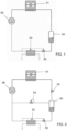
- the distribution of the cooling fluid to the evaporator or evaporators 52 occurs in most cases from a liquid tank 50 placed downstream of a high-pressure exchanger (condenser) 51 (see Fig.1 ).
- the tank 50 is kept at the condensation pressure which is indirectly controlled by the thermal capacity of the cooling fluid (air or water) flow and by the geometric characteristics of the high-pressure exchanger 51.
- a lamination valve 53 is interposed between the high-pressure exchanger 51 and the tank 50, while the pressure in said tank is limited by expansion of the flash vapor at low pressure through a pressure regulating valve 54 provided downstream of said tank 50 (see Figure 2 ).
- the distribution of refrigerating fluid to the evaporator or to the evaporators 52 occurs by means of a thermostatic expansion valve 55, of the mechanical or electronic type, which regulates overheating.
- the dry vapor coming out from the evaporators 52 passes through the compressor 56 which increases its pressure and then is sent to the high-pressure exchanger 51 to be cooled and brought back to the liquid state, to be finally returned to the liquid tank 50.
- WO2012/092685 describes a refrigeration circuit which is provided with an ejector and a single evaporator, which is connected via a fluidic circuit at the inlet with the tank and at the outlet with the inlet of an ejector module provided for the fluidized bed flow.
- the object of the invention is to propose refrigerating circuit which overcomes the drawbacks of traditional solutions and which, regardless of the used refrigerant, has a high efficiency.
- Another object of the invention is to propose a circuit which exhibits high efficiency even by using carbon dioxide as refrigerant.
- Another object of the invention is to propose a circuit which has a high efficiency even in the presence of a high external environmental temperature, for example during the summer period.
- Another object of the invention is to propose a circuit which can be used in all operating conditions.
- Another object of the invention is to propose a flexible circuit which can be readily and correctly adapted to, even significant, variations in its operating use condition.
- Another object of the invention is to propose a circuit which can be produced in a simple, easy and low-cost manner.
- Another object of the invention is to propose a circuit which has an alternative and/or improved characterization, both in constructive and functional terms, with respect to the traditional ones.
- the refrigeration circuit according to the invention comprises at least one compressor 1 which is installed so as to suck refrigerating fluid in the vapor state 7 from a tank 4 through a pipe 3 which connects the upper part of said tank 4 with the suction port of said compressor 1.
- the tank 4 contains refrigerating fluid in both the liquid state 5 and the vapor state 7.
- the circuit 20 comprises a plurality of compressors 1 in parallel with each other and configured to suck the refrigerating fluid in the vapor state 7 from the tank 4.
- the discharge port of the compressor 1 is connected to the inlet of a high-pressure heat exchanger 2.
- the heat exchanger 2 comprises a condenser, in which the refrigerating fluid in the vapor state 7 and at high-pressure - as compressed by the compressor 1 - is cooled and brought to the liquid state or dense gas.
- the cooling fluid is cooled by exchanging heat with the external environment or with another fluid.
- the high-pressure exchanger 2 provides that the cooling fluid exchanges heat with a fluid to be heated (for example water) which enters the high-pressure exchanger 2 from an inlet 27 and - after passing through said high-pressure exchanger 2 in order to exchange heat with the refrigerating fluid compressed by the compressor 1 - leaves the high-pressure exchanger 2 from an outlet 29.
- a fluid to be heated for example water
- the circuit 20 further comprises a pipe 9 which connects the outlet of the high-pressure exchanger 2 with the input 8 M of an ejector module 8 (unit).
- the ejector module 8 comprises:
- the ejector module 8 comprises at least one ejector 8' provided with a convergent nozzle 60 which is associated with the input 8 M for the motor fluid and communicates at the outlet with a suction chamber 62; in particular, said suction chamber 62 is defined inside the same ejector 8' and communicates with the input 8 T for the entrained flow.
- the ejector 8' comprises a mixing chamber 64 which terminates and is connected downstream with a diffuser 69.
- the mixing chamber 64 is connected upstream with the suction chamber 62, while the diffuser 69 is connected downstream with the output 8 OUT .
- the ejector module 8 may comprise a single variable geometry ejector (not shown).
- this ejector comprises a convergent nozzle 60 in which the outlet section is appropriately adjusted, for example by means of a pin, according to the pressure value measured downstream of the compressor 1.
- the ejector module 8 can be of fixed geometry and comprise a plurality of ejectors 8' in parallel (multi-ejector), of the same or variable size (or a suitable combination thereof), which are activated/controlled based on the pressure value measured downstream from the compressor 1.
- the ejector module 8 comprises a plurality of shut-off valves 11, preferably of the on-off type, controlled in parallel and positioned at the input of the nozzle 62 of each ejector 8'.
- connection 12 is provided to divide the flow coming from the pipe 9 into a plurality of ducts, each of which is provided with its own shut-off valve 71 and it enters at the input 8 M of an ejector 8'.
- the outputs 8 OUT of each ejector 8' are connected to a manifold 13 communicating, through the duct 14, with the tank 4.
- control/command unit 91 of the ejector module 8 and in particular of the pin, in the case of a single variable geometry ejector, or of shut-off valves 11, in the configuration with a plurality of parallel ejectors 8'.
- control/command unit 91 is configured to control the ejector module 8, according to known algorithms, on the basis of the detected (by means of appropriate sensors 93) temperature and pressure values in any area of the outlet pipe 9, that is, in any zone positioned between the outlet of the high-pressure exchanger 2 and the input of the ejector module itself.
- the ejector module 8 controls/regulates the pressure of the refrigerating fluid at the input 8 M , on the basis of the temperature and pressure values measured in any area of the outlet pipe 9, according to a traditional efficiency optimization curve of a transcritical CO 2 cycle.
- the circuit 20 also comprises a first evaporator 24 which, suitably, is gravity fed from the liquid tank 4 via a portion 50 and which at the outlet is connected directly to the tank by a recirculation circuit 21.
- the first evaporator 24 is placed at a lower geodetic level with respect to the tank 4 so as to allow gravity feeding of said first evaporator 24 with the refrigerating liquid 5 present in the tank itself.
- the outlet of the first evaporator 24 is connected to the liquid tank 4 by means of a recirculation circuit 21 in which the circulation of the refrigerating fluid occurs by density difference between the saturated liquid entering the first evaporator 24 and the liquid/vapor mixture or the vapor coming out of the latter, which, being lighter, enters the recirculation circuit 21.
- the circuit 20 also comprises a second evaporator 30 which is connected at the inlet with the tank 4 and at the outlet with the input 8 T of the ejector module 8.
- the second evaporator 30 is supplied with liquid refrigerating fluid 5, present in the liquid tank 4, by means of a portion 51 provided with an expansion valve 32 which is controlled by a control/command unit (not shown), preferably but not exclusively, based on the temperature (overheating) and/or pressure of the refrigerating fluid that is present, preferably in the vapor state, in correspondence of the pipe 10 positioned at the outlet of the second evaporator 30.
- the outlet of the second evaporator 30 is connected by the pipe 10 to the input 8 T of the ejector module 8.
- a connection portion 15 is provided for dividing the entrained flow of the pipe 10 into a plurality of suction ducts 16, each of which communicates with the entrained input (suction port) 8 T of one of the ejectors 8' of the module 8.
- a valve 17, preferably a non-return valve, is provided at each suction duct 16.
- P 1 corresponds to the pressure of the refrigerating fluid in the pipe 10 connected to the input 8 T ; while P 2 corresponds to the pressure of the two-phase refrigerating fluid in the tank 4, the fraction thereof in the vapor state 7 is sucked by the compressor 1.
- compressor 1 sucks from the tank 4 the refrigerating fluid in the vapor state 7 at a higher pressure P 2
- the ejector module 8 sucks/drags the refrigerating fluid through the input 8 T at a lower pressure level P 1 .
- the path 40 of the fluid to be cooled is configured in such a way as to pass in sequence the two evaporators 24 and 30 which, advantageously, are connected to each other in series, preferably on the side in which the fluid to be cooled flows.
- the path 40 of the fluid to be cooled comprises in sequence firstly the crossing of a first portion 41 provided on the primary side of the first gravity fed evaporator 24, which can be connected following or against the current, and subsequently comprises the crossing of a second portion 42 defined on the primary side of the second evaporator 30, the one fed through the expansion valve 32 and whose outlet is connected to the input 8 T of the ejector module 8.
- the second portion 42 of the second evaporator 30 is fluidically connected in series and downstream of the first portion 41 of the first evaporator 24.
- the circuit 20 of fig. 3 also comprises a further suitable control unit (not shown) for the temperature of the fluid to be cooled, for example water or other liquid, inside the path 40.
- said further control unit is configured to act on the suction pressure of the refrigerating fluid from the tank 4, in particular by acting on the suction capacity of the compressor 1 - and therefore on the saturation temperature of the refrigerating fluid in said tank 4 - so that the temperature of the cooled fluid detected downstream of said second evaporator 30 follows a determined reference temperature (set-point).
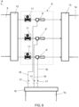
- the path 40 of the fluid to be cooled for example air or other gas, comprises at least one duct 45 in which they are inserted/housed in sequence (i.e. one after the other according to the crossing direction of said channel) the two evaporators 24 and 30.
- a fan 46 can be provided for the circulation of the air which passes through said ducting.
- the path 40 of the air to be cooled inside the duct 45 comprises in sequence: first the crossing of the secondary side of the first evaporator 24 fed by gravity, and subsequently the crossing of the secondary side of the second evaporator 30, that is fed by the expansion valve 32 and which output is connected to the input 8 T of the ejector module 8.
- a control/command unit 91 of the ejector module 8 is provided, and in particular for the control of the pin in the case of a single variable geometry ejector or of the shut-off valves 11 in the case of a configuration with a plurality of parallel ejectors 8'.
- said control/command unit 91 is configured to control the ejector module 8, according to known algorithms, on the basis of the temperature and pressure values detected (by appropriate sensors 93) in any area of the outlet pipe 9, i.e. in any area positioned between the outlet of the high-pressure exchanger 2 and the input 8 M of the ejector module 8 itself.
- the second evaporator 30 is supplied with refrigerating fluid 5 in the liquid state, which is present in the liquid tank 4, through a portion 51 provided with an expansion valve 32 which is controlled by the command/control unit 91, preferably but not exclusively, on the basis of the temperature T 1 and/or pressure P 1 of the refrigerating fluid which is present, preferably in the vapor state, in correspondence of the pipe 10 positioned at the outlet of the second evaporator 30.
- the circuit 20 also comprises a further capacity control unit (not shown) which is configured to act on the suction pressure of the refrigerating fluid from the tank 4, in particular by acting on the suction capacity of the compressor 1 - and therefore on the temperature saturation of the refrigerating fluid in said tank 4 - so that the temperature T out of the fluid (for example water) at the outlet 29 of the high-pressure exchanger 2 follows a determined reference temperature (set-point).
- the temperature T out of the fluid corresponds to the temperature that the fluid presents after it has exchanged heat with the refrigerating fluid compressed by the compressor 1 inside the high-pressure exchanger 2.
- the overheat is defined by the temperature difference ⁇ T between T SAT1 and T 1 (i.e.
- T SAT1 the saturation temperature corresponding to the pressure P 1 of the refrigerating fluid in the pipe 10 connected to the input 8 T while T 1 is the corresponding temperature of the refrigerating fluid in the pipe 10 connected to the input 8 T .
- control units of the circuit 20 can be implemented by separate processors or, alternatively, can be implemented inside the same processor.
- circuit 20 The operation of the circuit 20 according to the invention is as follows.
- the fluid to be cooled which enters in the path 40 at a temperature T 1 , for example of about 12°C, first passes through the first evaporator 24 where it passes to a temperature T 2 , for example about 9°C (see section 81 of the temperature profile 80 of the fluid to be cooled which passes through the first evaporator 24).
- T 1 to T 2 of the fluid to be cooled is obtained, inside the first evaporator 24, by heat exchange with the refrigerating fluid which evaporates at a temperature of, for example, about 8°C (see section 85 of the temperature profile 83 of the refrigerating fluid passing through the first evaporator 24).
- the heat that passes from the fluid to be cooled to the refrigerating fluid causes the latter to pass from the liquid state to the state of a two-phase liquid/vapor or vapor mixture which, in view of its lower density and through the recirculation circuit 21, returns in the tank 4 in the form of a two-phase mixture or vapor having a temperature of about 8°C for example.
- T 3 a temperature
- this further decrease in temperature from T 2 to T 3 of the fluid to be cooled is obtained, inside the second evaporator 30, by the heat exchange with the refrigerating fluid which is in the liquid state and at the temperature of about 4°C (see section 84 of the temperature profile 83 of the refrigerating fluid passing through the second evaporator 30).
- the temperature of the refrigerating fluid entering the second evaporator 30 passes from a temperature of, for example, about 8°C (corresponding to the temperature of the refrigerating fluid inside the tank 4) at the aforementioned temperature of about 4°C.
- the reduction (fall) of pressure that occurs inside the ejector module 8 causes a lowering of the pressure and therefore of the temperature, for example from 8°C to 4°C, of the refrigerating fluid entering the second evaporator 30 and circulating in the pipe 10 associated with the input 8 T .
- the heat that passes from the fluid to be cooled to the refrigerating fluid causes the latter to pass from the liquid state to the vapor state which is then sucked through the pipe 10 and the input 8 T inside the ejector 8.
- the refrigerating fluid is at a temperature of, for example, about 8°C, both in the liquid state 5 and in the vapor state 7.
- the compressor 1 sucks from the tank 4 the refrigerating fluid in the vapor state 7 - which is for example at a pressure of about 42 bar and at a temperature of about 8°C - and, after compressing it, increasing its pressure up to about 90 bar (at a temperature of about 100° -120°C), sends it to the high-pressure exchanger 2 where it is cooled - if the air or the cooling fluid is at about 32-33°C - for example, to reach a temperature of about 35°C (with pressure remaining around 90 bar), and brought to a liquid or dense gas state.
- the refrigerating liquid or dense gas which is at high pressure (i.e. at about 90bar) and at the temperature of 35°C, which exits the high-pressure exchanger 2, is sent to the input 8 M of the ejector module 8.
- the high-pressure refrigerating liquid which enters through the input 8 M (see section 70 of the pressure profile shown in Fig. 4 ), is passed through the convergent nozzle 60 so as to convert the pressure into velocity and create a sudden reduction in pressure inside the suction chamber 62 of the ejector module (see the second section 72 of the pressure profile shown in Fig. 4 ).
- the aforementioned pressure reduction causes the suction/aspiration, inside the suction chamber 62 and through the input 8 T , of the refrigerating fluid which flows from the tank 4 through the second evaporator 30.
- the vapor present in the pipe 10 at the outlet of the second evaporator 30 (see section 74 of the pressure profile shown in Fig. 4 ) is sucked/aspirated inside the suction chamber 62 of the ejector module 8.
- the mixing chamber (diffuser) 64 which is provided in the ejector module 8 immediately downstream of the suction chamber, the refrigerating liquid or dense gas, which has entered through the input 8 M , mixes with the sucked/aspirated one in the vapor state that enters through the input 8 T (see section 76 of the pressure profile shown in Fig. 4 ).
- the mixture so obtained is compressed in the diffuser 69 (see section 78 of the pressure profile shown in Fig.
- the diffuser 69 downstream of the mixing chamber 64 is suitably shaped as a divergent duct and defines the chamber pressure recovery.
- the pressure reduction which is carried out, in a controlled manner, at the input 8 M causes, through the input 8 T , the circulation of the refrigerating fluid through the second evaporator 30, thus allowing a further lowering of the temperature of the fluid to be cooled.
- the ejector module 8 reduces, before the injection in the tank 4 connected to the compressor 1, the pressure (and therefore the temperature) of the refrigerating fluid coming out from the high-pressure exchanger 2 and this allows the recovery of the expansion energy and at the same time, it increases efficiency, particularly in summer conditions, i.e. when the outside air is hot and does not allow a suitable cooling of the refrigerating fluid that passes through the high-pressure exchanger 2.
- the ejector module 8 also allows to increase the pressure (and therefore the temperature) of the refrigerating fluid coming out from the second evaporator 30 before placing it in tank 4 connected to the compressor 1. Therefore, the compressor 1 sucks, from the tank 4, the refrigerating fluid in the vapor state 7 which is at a pressure higher than the outlet pressure from the second evaporator 30, and therefore the energy required for its compression is lower.
- the ratio (called “Entrainment Ratio ”) between the flow rate through the input 8 T and the flow rate through the input 8 M of the ejector module 8 depends on the temperature and pressure of the refrigerating fluid at the input 8 M .
- the above ratio is higher in summer conditions - that is when the cooling fluid (the outside air) is warmer - and therefore it is possible to recover a greater amount of energy suitable to generate a pressure difference that would induce circulation, through the second evaporator 30, of a greater refrigerating fluid flow that evaporates at a temperature lower than the saturation temperature corresponding to the suction pressure of the compressor 1.
- circuit according to the invention can be used for cooling water or other liquids in conditioning or environmental comfort systems, in refrigeration systems and/or in industrial processes.
- the operation of the circuit according to the invention in its embodiment of fig. 7 substantially corresponds to that described above, wherein the fluid to be cooled is air, which enters the path 40 defined by the duct 45, in order to first cross the first evaporator 24 (where there is a lowering of temperature from T 1 to T 2 ) and, subsequently, it passes through the second evaporator 30 (where a temperature drop from T 2 to T 3 occurs).
- the circuit according to the invention is particularly advantageous because:
- the invention is particularly suitable for use with natural refrigerating fluids, such as in particular carbon dioxide (CO2 or R744), but it can also be used also with synthetic refrigerants.
- natural refrigerating fluids such as in particular carbon dioxide (CO2 or R744)
- CO2 or R744 carbon dioxide
Landscapes
- Engineering & Computer Science (AREA)
- Physics & Mathematics (AREA)
- Mechanical Engineering (AREA)
- Thermal Sciences (AREA)
- General Engineering & Computer Science (AREA)
- Chemical & Material Sciences (AREA)
- Chemical Kinetics & Catalysis (AREA)
- Jet Pumps And Other Pumps (AREA)
Applications Claiming Priority (1)
| Application Number | Priority Date | Filing Date | Title |
|---|---|---|---|
| IT201700130508 | 2017-11-15 |
Publications (3)
| Publication Number | Publication Date |
|---|---|
| EP3486580A1 EP3486580A1 (en) | 2019-05-22 |
| EP3486580C0 EP3486580C0 (en) | 2024-07-17 |
| EP3486580B1 true EP3486580B1 (en) | 2024-07-17 |
Family
ID=61527280
Family Applications (1)
| Application Number | Title | Priority Date | Filing Date |
|---|---|---|---|
| EP18206266.1A Active EP3486580B1 (en) | 2017-11-15 | 2018-11-14 | An improved refrigeration circuit |
Country Status (3)
| Country | Link |
|---|---|
| EP (1) | EP3486580B1 (pl) |
| ES (1) | ES2988440T3 (pl) |
| PL (1) | PL3486580T3 (pl) |
Families Citing this family (3)
| Publication number | Priority date | Publication date | Assignee | Title |
|---|---|---|---|---|
| IT201900010572A1 (it) * | 2019-07-01 | 2021-01-01 | Enex S R L | Impianto di refrigerazione perfezionato |
| AU2020395172B9 (en) * | 2019-12-04 | 2022-07-21 | Bechtel Energy Technologies & Solutions, Inc. | Systems and methods for implementing ejector refrigeration cycles with cascaded evaporation stages |
| DE102023211619A1 (de) * | 2023-11-22 | 2025-06-05 | Volkswagen Aktiengesellschaft | Klimatisierungsanordnung mit parallel angeordneten Ejektoren |
Family Cites Families (4)
| Publication number | Priority date | Publication date | Assignee | Title |
|---|---|---|---|---|
| US2617264A (en) * | 1950-03-20 | 1952-11-11 | Mojonnier Bros Co | Evaporator structure in refrigerating apparatus |
| DE102006024211A1 (de) * | 2005-05-24 | 2007-01-25 | Denso Corp., Kariya | Ejektorpumpe und Ejektorpumpenkreisvorrichtung |
| WO2012092685A1 (en) | 2011-01-04 | 2012-07-12 | Carrier Corporation | Ejector |
| US9683762B2 (en) * | 2012-10-10 | 2017-06-20 | Panasonic Intellectual Property Management Co., Ltd. | Heat exchanging device and heat pump |
-
2018
- 2018-11-14 PL PL18206266.1T patent/PL3486580T3/pl unknown
- 2018-11-14 EP EP18206266.1A patent/EP3486580B1/en active Active
- 2018-11-14 ES ES18206266T patent/ES2988440T3/es active Active
Also Published As
| Publication number | Publication date |
|---|---|
| EP3486580C0 (en) | 2024-07-17 |
| ES2988440T3 (es) | 2024-11-20 |
| EP3486580A1 (en) | 2019-05-22 |
| PL3486580T3 (pl) | 2024-11-25 |
Similar Documents
| Publication | Publication Date | Title |
|---|---|---|
| US10823461B2 (en) | Ejector refrigeration circuit | |
| EP3543628B1 (en) | Ejector cycle | |
| EP3102891B1 (en) | Ejector cycle heat recovery refrigerant separator | |
| JP4358832B2 (ja) | 冷凍空調装置 | |
| US10544971B2 (en) | Method for controlling a vapour compression system with an ejector | |
| EP2504640B1 (en) | High efficiency ejector cycle | |
| JP4984453B2 (ja) | エジェクタ式冷凍サイクル | |
| EP2596303B1 (en) | High efficiency ejector cycle | |
| ES2934690T3 (es) | Circuito de refrigeración de eyector | |
| CN115234993B (zh) | 空调装置 | |
| EP3486580B1 (en) | An improved refrigeration circuit | |
| CN101512248A (zh) | 空调装置 | |
| JP2008224189A (ja) | 冷凍サイクル装置 | |
| JP2009133624A (ja) | 冷凍空調装置 | |
| CN105240962A (zh) | 一种风温范围宽泛的水冷调温除湿机 | |
| KR102184235B1 (ko) | 액체 온조 장치 및 온도 제어 시스템 | |
| CN101910762A (zh) | 使用可调整膨胀阀来控制去湿 | |
| WO2016188777A1 (en) | A vapour compression system with an ejector and a non-return valve | |
| WO2017037771A1 (ja) | 冷凍サイクル装置 | |
| EP3999791B1 (en) | Chiller system with multiple compressors | |
| EP3217120A1 (en) | Outdoor unit for air conditioner | |
| US20190032985A1 (en) | Refrigeration device comprising multiple storage chambers | |
| EP3805663A1 (en) | Supercritical steam compression-type refrigeration cycle and liquid heating device | |
| JP5641004B2 (ja) | 冷凍サイクル装置 | |
| JP2015143597A (ja) | 給湯装置 |
Legal Events
| Date | Code | Title | Description |
|---|---|---|---|
| PUAI | Public reference made under article 153(3) epc to a published international application that has entered the european phase |
Free format text: ORIGINAL CODE: 0009012 |
|
| STAA | Information on the status of an ep patent application or granted ep patent |
Free format text: STATUS: THE APPLICATION HAS BEEN PUBLISHED |
|
| AK | Designated contracting states |
Kind code of ref document: A1 Designated state(s): AL AT BE BG CH CY CZ DE DK EE ES FI FR GB GR HR HU IE IS IT LI LT LU LV MC MK MT NL NO PL PT RO RS SE SI SK SM TR |
|
| AX | Request for extension of the european patent |
Extension state: BA ME |
|
| STAA | Information on the status of an ep patent application or granted ep patent |
Free format text: STATUS: REQUEST FOR EXAMINATION WAS MADE |
|
| 17P | Request for examination filed |
Effective date: 20191118 |
|
| RBV | Designated contracting states (corrected) |
Designated state(s): AL AT BE BG CH CY CZ DE DK EE ES FI FR GB GR HR HU IE IS IT LI LT LU LV MC MK MT NL NO PL PT RO RS SE SI SK SM TR |
|
| RAP1 | Party data changed (applicant data changed or rights of an application transferred) |
Owner name: ENEX S.R.L. |
|
| RIN1 | Information on inventor provided before grant (corrected) |
Inventor name: GIROTTO SERGIO |
|
| RIN1 | Information on inventor provided before grant (corrected) |
Inventor name: GIROTTO SERGIO |
|
| STAA | Information on the status of an ep patent application or granted ep patent |
Free format text: STATUS: EXAMINATION IS IN PROGRESS |
|
| 17Q | First examination report despatched |
Effective date: 20210907 |
|
| P01 | Opt-out of the competence of the unified patent court (upc) registered |
Effective date: 20230518 |
|
| RAP3 | Party data changed (applicant data changed or rights of an application transferred) |
Owner name: ENEX S.R.L. |
|
| GRAP | Despatch of communication of intention to grant a patent |
Free format text: ORIGINAL CODE: EPIDOSNIGR1 |
|
| STAA | Information on the status of an ep patent application or granted ep patent |
Free format text: STATUS: GRANT OF PATENT IS INTENDED |
|
| INTG | Intention to grant announced |
Effective date: 20240424 |
|
| RIN1 | Information on inventor provided before grant (corrected) |
Inventor name: GIROTTO SERGIO |
|
| GRAS | Grant fee paid |
Free format text: ORIGINAL CODE: EPIDOSNIGR3 |
|
| GRAA | (expected) grant |
Free format text: ORIGINAL CODE: 0009210 |
|
| STAA | Information on the status of an ep patent application or granted ep patent |
Free format text: STATUS: THE PATENT HAS BEEN GRANTED |
|
| AK | Designated contracting states |
Kind code of ref document: B1 Designated state(s): AL AT BE BG CH CY CZ DE DK EE ES FI FR GB GR HR HU IE IS IT LI LT LU LV MC MK MT NL NO PL PT RO RS SE SI SK SM TR |
|
| REG | Reference to a national code |
Ref country code: CH Ref legal event code: EP |
|
| REG | Reference to a national code |
Ref country code: DE Ref legal event code: R096 Ref document number: 602018071809 Country of ref document: DE |
|
| REG | Reference to a national code |
Ref country code: IE Ref legal event code: FG4D |
|
| U01 | Request for unitary effect filed |
Effective date: 20240801 |
|
| P04 | Withdrawal of opt-out of the competence of the unified patent court (upc) registered |
Free format text: CASE NUMBER: APP_48688/2024 Effective date: 20240826 |
|
| U07 | Unitary effect registered |
Designated state(s): AT BE BG DE DK EE FI FR IT LT LU LV MT NL PT RO SE SI Effective date: 20240902 |
|
| U20 | Renewal fee for the european patent with unitary effect paid |
Year of fee payment: 7 Effective date: 20241010 |
|
| REG | Reference to a national code |
Ref country code: ES Ref legal event code: FG2A Ref document number: 2988440 Country of ref document: ES Kind code of ref document: T3 Effective date: 20241120 |
|
| P05 | Withdrawal of opt-out of the competence of the unified patent court (upc) changed |
Free format text: CASE NUMBER: APP_48688/2024 Effective date: 20240902 |
|
| PG25 | Lapsed in a contracting state [announced via postgrant information from national office to epo] |
Ref country code: GR Free format text: LAPSE BECAUSE OF FAILURE TO SUBMIT A TRANSLATION OF THE DESCRIPTION OR TO PAY THE FEE WITHIN THE PRESCRIBED TIME-LIMIT Effective date: 20241018 |
|
| PGFP | Annual fee paid to national office [announced via postgrant information from national office to epo] |
Ref country code: PL Payment date: 20241011 Year of fee payment: 7 |
|
| PG25 | Lapsed in a contracting state [announced via postgrant information from national office to epo] |
Ref country code: IS Free format text: LAPSE BECAUSE OF FAILURE TO SUBMIT A TRANSLATION OF THE DESCRIPTION OR TO PAY THE FEE WITHIN THE PRESCRIBED TIME-LIMIT Effective date: 20241117 |
|
| PG25 | Lapsed in a contracting state [announced via postgrant information from national office to epo] |
Ref country code: HR Free format text: LAPSE BECAUSE OF FAILURE TO SUBMIT A TRANSLATION OF THE DESCRIPTION OR TO PAY THE FEE WITHIN THE PRESCRIBED TIME-LIMIT Effective date: 20240717 |
|
| PGFP | Annual fee paid to national office [announced via postgrant information from national office to epo] |
Ref country code: IE Payment date: 20241010 Year of fee payment: 7 |
|
| PG25 | Lapsed in a contracting state [announced via postgrant information from national office to epo] |
Ref country code: RS Free format text: LAPSE BECAUSE OF FAILURE TO SUBMIT A TRANSLATION OF THE DESCRIPTION OR TO PAY THE FEE WITHIN THE PRESCRIBED TIME-LIMIT Effective date: 20241017 |
|
| PGFP | Annual fee paid to national office [announced via postgrant information from national office to epo] |
Ref country code: ES Payment date: 20241212 Year of fee payment: 7 |
|
| PG25 | Lapsed in a contracting state [announced via postgrant information from national office to epo] |
Ref country code: RS Free format text: LAPSE BECAUSE OF FAILURE TO SUBMIT A TRANSLATION OF THE DESCRIPTION OR TO PAY THE FEE WITHIN THE PRESCRIBED TIME-LIMIT Effective date: 20241017 Ref country code: IS Free format text: LAPSE BECAUSE OF FAILURE TO SUBMIT A TRANSLATION OF THE DESCRIPTION OR TO PAY THE FEE WITHIN THE PRESCRIBED TIME-LIMIT Effective date: 20241117 Ref country code: HR Free format text: LAPSE BECAUSE OF FAILURE TO SUBMIT A TRANSLATION OF THE DESCRIPTION OR TO PAY THE FEE WITHIN THE PRESCRIBED TIME-LIMIT Effective date: 20240717 Ref country code: GR Free format text: LAPSE BECAUSE OF FAILURE TO SUBMIT A TRANSLATION OF THE DESCRIPTION OR TO PAY THE FEE WITHIN THE PRESCRIBED TIME-LIMIT Effective date: 20241018 |
|
| PGFP | Annual fee paid to national office [announced via postgrant information from national office to epo] |
Ref country code: CH Payment date: 20241201 Year of fee payment: 7 |
|
| PG25 | Lapsed in a contracting state [announced via postgrant information from national office to epo] |
Ref country code: SM Free format text: LAPSE BECAUSE OF FAILURE TO SUBMIT A TRANSLATION OF THE DESCRIPTION OR TO PAY THE FEE WITHIN THE PRESCRIBED TIME-LIMIT Effective date: 20240717 |
|
| PG25 | Lapsed in a contracting state [announced via postgrant information from national office to epo] |
Ref country code: CZ Free format text: LAPSE BECAUSE OF FAILURE TO SUBMIT A TRANSLATION OF THE DESCRIPTION OR TO PAY THE FEE WITHIN THE PRESCRIBED TIME-LIMIT Effective date: 20240717 |
|
| PG25 | Lapsed in a contracting state [announced via postgrant information from national office to epo] |
Ref country code: SK Free format text: LAPSE BECAUSE OF FAILURE TO SUBMIT A TRANSLATION OF THE DESCRIPTION OR TO PAY THE FEE WITHIN THE PRESCRIBED TIME-LIMIT Effective date: 20240717 |
|
| PLBE | No opposition filed within time limit |
Free format text: ORIGINAL CODE: 0009261 |
|
| STAA | Information on the status of an ep patent application or granted ep patent |
Free format text: STATUS: NO OPPOSITION FILED WITHIN TIME LIMIT |
|
| 26N | No opposition filed |
Effective date: 20250422 |
|
| PG25 | Lapsed in a contracting state [announced via postgrant information from national office to epo] |
Ref country code: MC Free format text: LAPSE BECAUSE OF FAILURE TO SUBMIT A TRANSLATION OF THE DESCRIPTION OR TO PAY THE FEE WITHIN THE PRESCRIBED TIME-LIMIT Effective date: 20240717 |
|
| U20 | Renewal fee for the european patent with unitary effect paid |
Year of fee payment: 8 Effective date: 20251016 |
|
| REG | Reference to a national code |
Ref country code: CH Ref legal event code: U11 Free format text: ST27 STATUS EVENT CODE: U-0-0-U10-U11 (AS PROVIDED BY THE NATIONAL OFFICE) Effective date: 20251201 |
|
| PGFP | Annual fee paid to national office [announced via postgrant information from national office to epo] |
Ref country code: GB Payment date: 20251016 Year of fee payment: 8 |
|
| PGFP | Annual fee paid to national office [announced via postgrant information from national office to epo] |
Ref country code: NO Payment date: 20251020 Year of fee payment: 8 |