EP3486443A1 - Piston cooling jets - Google Patents
Piston cooling jets Download PDFInfo
- Publication number
- EP3486443A1 EP3486443A1 EP18205959.2A EP18205959A EP3486443A1 EP 3486443 A1 EP3486443 A1 EP 3486443A1 EP 18205959 A EP18205959 A EP 18205959A EP 3486443 A1 EP3486443 A1 EP 3486443A1
- Authority
- EP
- European Patent Office
- Prior art keywords
- nozzle
- oil
- supply line
- spray system
- oil spray
- Prior art date
- Legal status (The legal status is an assumption and is not a legal conclusion. Google has not performed a legal analysis and makes no representation as to the accuracy of the status listed.)
- Withdrawn
Links
Images


Classifications
-
- F—MECHANICAL ENGINEERING; LIGHTING; HEATING; WEAPONS; BLASTING
- F01—MACHINES OR ENGINES IN GENERAL; ENGINE PLANTS IN GENERAL; STEAM ENGINES
- F01M—LUBRICATING OF MACHINES OR ENGINES IN GENERAL; LUBRICATING INTERNAL COMBUSTION ENGINES; CRANKCASE VENTILATING
- F01M1/00—Pressure lubrication
- F01M1/08—Lubricating systems characterised by the provision therein of lubricant jetting means
-
- F—MECHANICAL ENGINEERING; LIGHTING; HEATING; WEAPONS; BLASTING
- F01—MACHINES OR ENGINES IN GENERAL; ENGINE PLANTS IN GENERAL; STEAM ENGINES
- F01M—LUBRICATING OF MACHINES OR ENGINES IN GENERAL; LUBRICATING INTERNAL COMBUSTION ENGINES; CRANKCASE VENTILATING
- F01M1/00—Pressure lubrication
- F01M1/16—Controlling lubricant pressure or quantity
-
- F—MECHANICAL ENGINEERING; LIGHTING; HEATING; WEAPONS; BLASTING
- F01—MACHINES OR ENGINES IN GENERAL; ENGINE PLANTS IN GENERAL; STEAM ENGINES
- F01P—COOLING OF MACHINES OR ENGINES IN GENERAL; COOLING OF INTERNAL-COMBUSTION ENGINES
- F01P3/00—Liquid cooling
- F01P3/02—Arrangements for cooling cylinders or cylinder heads
-
- F—MECHANICAL ENGINEERING; LIGHTING; HEATING; WEAPONS; BLASTING
- F01—MACHINES OR ENGINES IN GENERAL; ENGINE PLANTS IN GENERAL; STEAM ENGINES
- F01P—COOLING OF MACHINES OR ENGINES IN GENERAL; COOLING OF INTERNAL-COMBUSTION ENGINES
- F01P3/00—Liquid cooling
- F01P3/06—Arrangements for cooling pistons
- F01P3/08—Cooling of piston exterior only, e.g. by jets
-
- F—MECHANICAL ENGINEERING; LIGHTING; HEATING; WEAPONS; BLASTING
- F01—MACHINES OR ENGINES IN GENERAL; ENGINE PLANTS IN GENERAL; STEAM ENGINES
- F01P—COOLING OF MACHINES OR ENGINES IN GENERAL; COOLING OF INTERNAL-COMBUSTION ENGINES
- F01P5/00—Pumping cooling-air or liquid coolants
- F01P5/10—Pumping liquid coolant; Arrangements of coolant pumps
-
- F—MECHANICAL ENGINEERING; LIGHTING; HEATING; WEAPONS; BLASTING
- F01—MACHINES OR ENGINES IN GENERAL; ENGINE PLANTS IN GENERAL; STEAM ENGINES
- F01M—LUBRICATING OF MACHINES OR ENGINES IN GENERAL; LUBRICATING INTERNAL COMBUSTION ENGINES; CRANKCASE VENTILATING
- F01M1/00—Pressure lubrication
- F01M1/08—Lubricating systems characterised by the provision therein of lubricant jetting means
- F01M2001/083—Lubricating systems characterised by the provision therein of lubricant jetting means for lubricating cylinders
-
- F—MECHANICAL ENGINEERING; LIGHTING; HEATING; WEAPONS; BLASTING
- F01—MACHINES OR ENGINES IN GENERAL; ENGINE PLANTS IN GENERAL; STEAM ENGINES
- F01M—LUBRICATING OF MACHINES OR ENGINES IN GENERAL; LUBRICATING INTERNAL COMBUSTION ENGINES; CRANKCASE VENTILATING
- F01M1/00—Pressure lubrication
- F01M1/08—Lubricating systems characterised by the provision therein of lubricant jetting means
- F01M2001/086—Lubricating systems characterised by the provision therein of lubricant jetting means for lubricating gudgeon pins
-
- F—MECHANICAL ENGINEERING; LIGHTING; HEATING; WEAPONS; BLASTING
- F01—MACHINES OR ENGINES IN GENERAL; ENGINE PLANTS IN GENERAL; STEAM ENGINES
- F01P—COOLING OF MACHINES OR ENGINES IN GENERAL; COOLING OF INTERNAL-COMBUSTION ENGINES
- F01P3/00—Liquid cooling
- F01P3/02—Arrangements for cooling cylinders or cylinder heads
- F01P2003/021—Cooling cylinders
-
- F—MECHANICAL ENGINEERING; LIGHTING; HEATING; WEAPONS; BLASTING
- F16—ENGINEERING ELEMENTS AND UNITS; GENERAL MEASURES FOR PRODUCING AND MAINTAINING EFFECTIVE FUNCTIONING OF MACHINES OR INSTALLATIONS; THERMAL INSULATION IN GENERAL
- F16N—LUBRICATING
- F16N7/00—Arrangements for supplying oil or unspecified lubricant from a stationary reservoir or the equivalent in or on the machine or member to be lubricated
- F16N7/30—Arrangements for supplying oil or unspecified lubricant from a stationary reservoir or the equivalent in or on the machine or member to be lubricated the oil being fed or carried along by another fluid
- F16N7/32—Mist lubrication
- F16N7/34—Atomising devices for oil
Definitions
- the present disclosure relates to a piston cooling jets, and more particularly to selectively tunable (e.g., spray direction and patterns) oil jets for cooling engine pistons.
- a piston and cylinder oil squirter system uses one or more squirter rails having an inlet connected to an oil source and one or more outlets connected to at least one oil supply rail.
- the oil supply rail includes a manifold with integral oil squirter nozzles and attachment brackets.
- An oil flow control valve placed before the oil supply manifold controls oil flow to the oil rails and nozzles in response to engine requirements.
- One drawback to such a system is that the oil is squirted (supplied) to the piston and cylinder on a constant basis, regardless of the position of the piston in the cylinder.
- an oil supply is repeatedly activated only during a part of a cylinder cycle synchronous with a frequency of piston reciprocating motion.
- oil supply may be provided during a portion of the engine cycle and not in a continuous manner.
- the system uses a series of poppet valves to control the flow of oil to each piston in which a piston skirt contacts the poppet valve to open the valve. While such a system functions to supply or spray oil at a desired location and time in the engine cycle, there is nevertheless contact between the piston skirt and poppet valve.
- Still other systems show that a cooling and lubricating jet of oil can be supplied to individual piston/cylinder combinations using, for example, the position of the crankshaft to control the flowrate and timing of oil flow to the piston, and an oil flow controller than controls the flowrate of oil to the piston in response to engine temperature.
- a system that is a drop-in rail or manifold system that includes a rail or manifold with a series of individual cooling jets or nozzles that can be directed at specific desired locations of the piston, for example at an area of the piston near the exhaust port or valve.
- a control device such as a solenoid valve, check valve, thermostatic valve or the like to control the flow of oil to the cooling jets.
- the manifold is not tied to any other critical galleries of the engine and can be shut off without isolating the oil supply to any other parts of the engine.
- An oil spray system for use in an engine includes a supply line and at least one nozzle mounted to the supply line.
- the at least one nozzle has at least one outlet, and, if more than one outlet or nozzle is present, the nozzles or outlets may spray oil in converging or diverging directions or patterns.
- the oil spray can be directed onto a piston or cylinder wall.
- One example spray pattern is a fan-spray pattern which can be provided by a slot-shaped outlet.
- the system includes a control device mounted to the supply line that controls the flow of oil to the at least one nozzle.
- the supply line is a manifold having at least two nozzles mounted thereto. Each nozzle includes at least one outlet.
- the terms nozzle or nozzles and jet or jets may be used interchangeably.
- the control device can be positioned between an oil supply and a first of the nozzles.
- the nozzles can be elements separate from the supply line or attached to the supply line.
- a connecting portion between the supply line and each nozzle extends outwardly from the supply line. This permits positioning of the nozzles to direct the oil flow to specific areas of the engine, such as the pistons, for example at an area of the piston near the exhaust port or valve.
- each nozzle includes one or more outlets and, when more than one outlet is present, the outlets are formed in the nozzle at different distances from a juncture of the nozzle and the supply line.
- the control device can be, for example, a solenoid valve, a thermostatic valve or a check valve.
- An embodiment of the oil spray system includes a supply line, a plurality of nozzles mounted to the supply line, each nozzle having at least one outlet and a control device mounted to the supply line, the control device controlling a supply of oil to the supply line.
- the nozzles and/or outlets are configurable to provide a predetermined spray direction or pattern.
- the supply line can be a manifold and the control device can be positioned at an end of the manifold.
- the nozzles can be formed as a continuous flow channel.
- the continuous flow channel is circular and extends around a base of the cylinder.
- the oil spray system includes an accumulator.
- the accumulator can be positioned on the supply line, between the control device and a first nozzle.
- the accumulator allows for oil flow and piston cooling on-demand regardless of the oil output of the oil pump or oil flow within the engine, engine speed or the like.
- the accumulator also dampens the supply of oil and delivery of oil to the piston and dampens pulsations in the manifold
- the nozzles can be formed having a tapered channel.
- the taper provides a reduced flow area from a first outlet to a second outlet and can be used to balance the oil flow to selected locations of the piston.
- the taper can be a stepwise taper or reduction in flow area.
- FIG. 1 illustrates a known oil spray system 1 for an engine.
- the oil spray system 1 includes a nozzle 2 from which a single stream of oil 3 is discharged or sprayed onto a single location within an engine.
- the oil spray is a constant spray of oil regardless of the operating conditions of the engine.
- the spray of oil is delivered when the engine oil pressure exceeds the threshold of the check valve.
- FIGS 2A-2C and 2E there is illustrated one embodiment of an oil spray system or piston cooling jet system 10.
- the system 10 is a rail or manifold system and includes a rail or manifold 12 with one or a series of individual cooling jets 14 directed at specific desired locations of the piston P.
- the system 10 can be controlled by a solenoid valve 16 as illustrated, or can be controlled by other means, such as a check valve, a thermostatic valve (thus operating by engine temperature), or the like.
- the engine block is not shown; rather, the system is shown relative to the engine crankshaft C and pistons P.
- the manifold 12 is not tied to any other critical galleries of the engine and can be shut off (as by isolating the solenoid valve), without isolating the oil supply to any other parts of the engine.
- the use of a separate manifold 12 reduces engine block casting machining, thus reducing the costs of using/manufacturing the system and the engine overall.
- the jet(s) or nozzle(s) 14 can be separately attached to the manifold 12 to allow for outlet angle and target adjustment. Because the nozzles 14 can separate from the manifold 12, the nozzles 14 can have single or multiple outlets 18 which allow for targeting multiple and specific locations on the piston P, such as the area of the piston at or near the cylinder exhaust port/valve.
- the illustrated rail/manifold system 10 can be configured as a "drop-in" system which is capable of installation in existing engine programs without significant modification or redesign of the engine, due to the solenoid 16 and manifold 12 being an all-in-one, e.g., self-contained, system. Oil can be supplied to the rail/manifold 12 via the solenoid 16 through an existing engine block oil gallery or oil pump passage.
- FIG. 2D illustrates an embodiment of the system 10' in which the manifold 12' is fitted without a controller (without a control valve).
- the manifold 12' may connect, for example, directly to an oil pump, engine block oil gallery, or other source such that the inlet or inlets from the oil source provide the oil directly to the manifold 12'.
- a control valve e.g., solenoid, check valve or the like
- FIGS. 3A-3D illustrate an oil spray system 110 having a planar jet 114 configuration.
- the system 110 includes a manifold 112 and a series of planar jets 114 extending from the manifold 112.
- the system 110 can be controlled by a solenoid valve 116 as illustrated, or it can be controlled by other means, such as a check valve, a thermostatic valve or the like.
- each nozzle 114 can include multiple outlets 118 to direct the oil spray to specific desired areas of the piston, such as the areas of the piston at or near the cylinder exhaust port/valve and intake port/valve (see, for example, FIG. 3C which shows one desired angle/direction of the oil spray S).
- the manifold 112 can be offset to one or both sides of the engine connecting rods to permit easy adaptation into existing engine designs.
- the system 110 is a "drop-in" system so that it is capable of installation in existing engine programs without significant modification or redesign, as the solenoid 116 and manifold 112 are an all-in-one, e.g., self-contained, system.
- oil can be supplied to the rail/manifold 112 via the solenoid 116 through an existing engine block oil gallery or oil pump passage.
- FIGS. 4A and 4B illustrate an embodiment of the system 210 similar to that of FIGS. 3A-3D , that includes an oil or hydraulic accumulator 220 for the manifold 212/solenoid 216 (or other control scheme) assembly.
- the accumulator 220 allows for oil flow and piston cooling on-demand regardless of the oil output of the oil pump or oil flow within the engine, engine speed or the like.
- the accumulator 220 dampens or smooths the supply of oil and delivery of oil to the piston and dampens pulsations in the manifold 212.
- Use of an accumulator 220 can also reduce the burden on the oil pump, which may allow for the use of a smaller engine oil pump.
- FIG. 5A illustrates a planer nozzle 314 that can be used individually as mounted to the engine, and fed individually, rather than through a manifold.
- the planar jet includes a body 322, an inlet side 324 and multiple outlets 318.
- the nozzles 314 include three outlets 318, but more or less outlets are contemplated to provide for spray in desired locations.
- the outlets 318 can be configured so that they can be directed to specific desired areas of the piston, such as the areas of the piston at or near the cylinder exhaust port/valve and intake port/valve (see, for example, FIG. 3C which shows one desired angle/direction of the oil spray).
- the body 322 of the nozzle 314 can be straight or offset to provide the desired spray locations/pattern.
- the nozzles 314 can be secured to the engine by brackets 330.
- FIG. 6 a sectional view an embodiment of the nozzle 314 shows a tapered cavity 326 formed in the jet body 322 in which the oil flows to the outlets 318.
- a tapered cavity 326 can be used to balance the oil flow to selected locations of the piston.
- FIGS. 7A and 7B An alternate embodiment of a nozzle 414 is illustrated in FIGS. 7A and 7B , in which the nozzle 414 has a cylindrical body 422 (in contrast to the flat nozzle 314 shape). Such a cylindrical body 422 shape can provide the same directed oil spray.
- the cylindrical nozzle 414 can have a tapered or stepped cavity 426 to balance the oil flow to selected locations of the piston.
- the cavity 426 taper can be a smooth taper from the inlet of the nozzle 414 to the end of the nozzle 414.
- the nozzle 414 can include a weld sleeve or collar 428 so that the nozzle 414 can be welded or otherwise secured to the oil supply line/manifold 412.
- FIG. 7C illustrates yet another embodiment of the nozzle 450 in which the outlets 452 include an elongated slot-like shape to provide a fan spray pattern.
- the nozzle 450 can include a single outlet 452, or, as shown, multiple (three shown) outlets 452.
- the nozzle 450 can be tapered to balance the oil flow to selected locations of the piston.
- Other shapes of both the single and multiple outlet 452 configurations are contemplated to provide one or more directed oil sprays. It will be appreciated that a nozzle can include outlets having different shapes to effect different spray patterns or directions.
- jet or nozzle 414 diameter and number of nozzles 414 can be optimized to the targeted location for each outlet 418.
- outlets 418 directed to the hotter exhaust side of the piston can be larger or the nozzles 414 can have additional openings or outlets.
- the internal features, facilitate manufacturing/tooling as well as provide the desired the flow characteristics for the nozzle 414 and outlets 418.
- FIGS. 8A-8D illustrate a radial jet manifold system 510.
- the radial manifold system 510 includes a series of radial jets 514 connected to one another to form a manifold 512 such that oil flows from, for example, a solenoid 516 or other control device (e.g., check valve, thermostatic valve or the like), to each of the radial jets 514.
- a solenoid 516 or other control device e.g., check valve, thermostatic valve or the like
- Each jet 514 can be configured with a series of outlets 518 to spray oil at specific targeted locations on the piston P.
- the radial jets 514 are located at the base B of the cylinder in the engine block (see, FIGS. 8A and 8B ).
- FIGS. 9A and 9B illustrate a similar radial jet system 610, with the jets 614 formed as individual jets, rather than connected to a manifold in series.
- Each jet 614 is mounted to the engine block, for example at the base of the cylinder bore (as in FIG. 8B ).
- the jets 614 can be mounted by a bracket 630 and can include a valve 616 for control, such as a check valve, a thermostatic valve or the like.
- the oil spray paths S for the jets 618 for the embodiments of FIGS. 8 and 9 can be as shown in FIG. 9B .
- the individual jets 614 can be controlled separately by a solenoid 616, check valve, thermostatic valve or a like control device.
- the geometry of the individual radial jets 614 can be a full, e.g., continuous, or partial circle as required or dictated by engine design considerations.
- FIGS. 10A-10C embodiments of the oil spray or piston cooling jet system 10-410, can be incorporated into existing engine components.
- the system 10-410 can be incorporated into the windage tray T of the engine.
- FIG. 10A is a bottom view of the engine.
- Manifolds or supply lines, such as that illustrated at 712 for the systems can be incorporated onto the top side (not shown) of the tray T.
- FIGS. 10B and 10C illustrate such an arrangement in which the manifold or manifolds 712 can be incorporated into the tray T.
- Manifolds or supply lines can be molded directly into a one-piece windage tray, without the need for separate, attached components.
- the manifolds 712 are mounted on either side of the tray T and a single oil supply port 716 feeds the manifolds 712.
- a manifold or cross-over supply line 736 can be used to fluidly connect the two manifolds 712 (or the two portions of the system).
- the jets 714 can be positioned extending from the manifolds 712 with nozzles and outlets as described herein.
Landscapes
- Engineering & Computer Science (AREA)
- Mechanical Engineering (AREA)
- General Engineering & Computer Science (AREA)
- Chemical & Material Sciences (AREA)
- Combustion & Propulsion (AREA)
- Lubrication Of Internal Combustion Engines (AREA)
Abstract
An oil spray system for use in an engine for spraying directly onto a piston or cylinder wall, includes a supply line having at least one nozzle mounted to the supply line and at least one outlet on the nozzle. The system can include a control device. The control device can be mounted to the supply line. The nozzle and/or outlet is configurable to provide a predetermined spray direction or pattern.
Description
- This application claims the benefit of and priority to Provisional
US Patent Application Serial No. 62/586,371, filed November 15, 2017 - The present disclosure relates to a piston cooling jets, and more particularly to selectively tunable (e.g., spray direction and patterns) oil jets for cooling engine pistons.
- There are continuing efforts to develop new and improved ways in which to cool engine pistons and cylinders. As engines become more efficient, run at higher compression ratios and cylinder pressures (e.g., turbocharging and supercharging) and emitting lower emissions, the engines, and in particular the pistons and cylinders run hotter, e.g., at higher temperatures. Increased thermal loading of pistons can, however, cause problems such as, engine degradation and seizures.
- While it is desirable to effectively and efficiently cool and/or lubricate the pistons and cylinders, incorporating systems to avoid such degradation can involve higher-cost materials and manufacturing methods. One known system, a piston and cylinder oil squirter system, uses one or more squirter rails having an inlet connected to an oil source and one or more outlets connected to at least one oil supply rail. The oil supply rail includes a manifold with integral oil squirter nozzles and attachment brackets. An oil flow control valve placed before the oil supply manifold controls oil flow to the oil rails and nozzles in response to engine requirements. One drawback to such a system is that the oil is squirted (supplied) to the piston and cylinder on a constant basis, regardless of the position of the piston in the cylinder.
- In another system an oil supply is repeatedly activated only during a part of a cylinder cycle synchronous with a frequency of piston reciprocating motion. In this way, oil supply may be provided during a portion of the engine cycle and not in a continuous manner. Such a system resolves the issue of a proportion of the oil supply being sprayed without cooling the piston due to the reciprocating motion of the piston. However, the system uses a series of poppet valves to control the flow of oil to each piston in which a piston skirt contacts the poppet valve to open the valve. While such a system functions to supply or spray oil at a desired location and time in the engine cycle, there is nevertheless contact between the piston skirt and poppet valve.
- Still other systems show that a cooling and lubricating jet of oil can be supplied to individual piston/cylinder combinations using, for example, the position of the crankshaft to control the flowrate and timing of oil flow to the piston, and an oil flow controller than controls the flowrate of oil to the piston in response to engine temperature.
- While all of the above-noted systems function to supply oil to the piston to effect piston cooling they all require fairly complex system to carry out timing and/or actuation of the oil spray to effect piston cooling.
- Accordingly, there is a need for a system that is a drop-in rail or manifold system that includes a rail or manifold with a series of individual cooling jets or nozzles that can be directed at specific desired locations of the piston, for example at an area of the piston near the exhaust port or valve. Desirably, such a system includes a control device, such as a solenoid valve, check valve, thermostatic valve or the like to control the flow of oil to the cooling jets.
- More desirably, in such a system, the manifold is not tied to any other critical galleries of the engine and can be shut off without isolating the oil supply to any other parts of the engine.
- An oil spray system for use in an engine includes a supply line and at least one nozzle mounted to the supply line. The at least one nozzle has at least one outlet, and, if more than one outlet or nozzle is present, the nozzles or outlets may spray oil in converging or diverging directions or patterns. The oil spray can be directed onto a piston or cylinder wall. One example spray pattern is a fan-spray pattern which can be provided by a slot-shaped outlet. In embodiments, the system includes a control device mounted to the supply line that controls the flow of oil to the at least one nozzle. In an embodiment, the supply line is a manifold having at least two nozzles mounted thereto. Each nozzle includes at least one outlet. For purposes of the present disclosure, the terms nozzle or nozzles and jet or jets may be used interchangeably.
- The control device can be positioned between an oil supply and a first of the nozzles. The nozzles can be elements separate from the supply line or attached to the supply line. A connecting portion between the supply line and each nozzle extends outwardly from the supply line. This permits positioning of the nozzles to direct the oil flow to specific areas of the engine, such as the pistons, for example at an area of the piston near the exhaust port or valve.
- In an embodiment, each nozzle includes one or more outlets and, when more than one outlet is present, the outlets are formed in the nozzle at different distances from a juncture of the nozzle and the supply line.
- The control device can be, for example, a solenoid valve, a thermostatic valve or a check valve.
- An embodiment of the oil spray system includes a supply line, a plurality of nozzles mounted to the supply line, each nozzle having at least one outlet and a control device mounted to the supply line, the control device controlling a supply of oil to the supply line. The nozzles and/or outlets are configurable to provide a predetermined spray direction or pattern.
- The supply line can be a manifold and the control device can be positioned at an end of the manifold. The nozzles can be formed as a continuous flow channel. In an embodiment, the continuous flow channel is circular and extends around a base of the cylinder.
- In an embodiment, the oil spray system includes an accumulator. The accumulator can be positioned on the supply line, between the control device and a first nozzle. The accumulator allows for oil flow and piston cooling on-demand regardless of the oil output of the oil pump or oil flow within the engine, engine speed or the like. The accumulator also dampens the supply of oil and delivery of oil to the piston and dampens pulsations in the manifold
- The nozzles can be formed having a tapered channel. The taper provides a reduced flow area from a first outlet to a second outlet and can be used to balance the oil flow to selected locations of the piston. The taper can be a stepwise taper or reduction in flow area.
- These and other features and advantages of the present device will be apparent from the following description, taken in conjunction with the accompanying sheets of drawings, and in conjunction with the appended claims.
- The benefits and advantages of the present embodiments will become more readily apparent to those of ordinary skill in the relevant art after reviewing the following detailed description and accompanying drawings, wherein:
-
FIG. 1 is a rendering of a prior art piston oil spray; -
FIGS. 2A-2E are various views of embodiments of an oil spray system showing a rail and manifold system, in whichFIGS. 2A-2C illustrate an embodiment having a solenoid controller,FIG. 2D illustrates an embodiment without a controller, andFIG. 2E illustrates a nozzle or jet with multiple outlets; -
FIGS. 3A-3D are various views of an embodiment of an oil spray system showing a planar jet manifold system; -
FIGS. 4A and 4B are various views of an embodiment of an oil spray system showing a planar jet manifold system similar to that illustrated inFIGS. 3A-3D , and further incorporates an accumulator in the system; -
FIGS. 5A and 5B illustrate an embodiment of an offset planar jet having directed spray paths; -
FIGS. 6 is a sectional view of an embodiment of a planar jet showing a tapered jet cavity; -
FIGS. 7A, 7B, and 7C are illustrations (FIG. 7B being a sectional view of the nozzle ofFIG. 7A ) a rail/manifold jet showing , inFIG. 7B , an example of a tapered or stepped nozzle cavity, andFIG. 7C showing yet another embodiment of the tapered nozzle; -
FIGS. 8A-8D are illustrations of an embodiment of the oil spray system showing a radial jet manifold; -
FIGS. 9A-9C are illustrations of an embodiment of the oil spray system showing a radial jet system with individual radial jets; and -
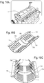
FIGS. 10A-10C are various views showing a mounting arrangement for an oil spray within an engine, in whichFIG. 10A is a bottom view of an engine showing a windage tray in place, andFIGS. 10B and 10C are view of a windage tray. - While the present disclosure is susceptible of embodiment in various forms, there is shown in the drawings and will hereinafter be described one or more embodiments with the understanding that the present disclosure is to be considered illustrative only and is not intended to limit the disclosure to any specific embodiment described or illustrated.
-
FIG. 1 illustrates a known oil spray system 1 for an engine. It will be appreciated that the oil spray system 1 includes anozzle 2 from which a single stream ofoil 3 is discharged or sprayed onto a single location within an engine. Although simplified, the oil spray is a constant spray of oil regardless of the operating conditions of the engine. In embodiments in which a check valve is used (as discussed further below), the spray of oil is delivered when the engine oil pressure exceeds the threshold of the check valve. - Referring now to
FIGS 2A-2C and2E , there is illustrated one embodiment of an oil spray system or pistoncooling jet system 10. Thesystem 10 is a rail or manifold system and includes a rail or manifold 12 with one or a series ofindividual cooling jets 14 directed at specific desired locations of the piston P. Thesystem 10 can be controlled by asolenoid valve 16 as illustrated, or can be controlled by other means, such as a check valve, a thermostatic valve (thus operating by engine temperature), or the like. InFIG. 2A , the engine block is not shown; rather, the system is shown relative to the engine crankshaft C and pistons P. In an embodiment, the manifold 12 is not tied to any other critical galleries of the engine and can be shut off (as by isolating the solenoid valve), without isolating the oil supply to any other parts of the engine. The use of aseparate manifold 12 reduces engine block casting machining, thus reducing the costs of using/manufacturing the system and the engine overall. - The jet(s) or nozzle(s) 14 can be separately attached to the manifold 12 to allow for outlet angle and target adjustment. Because the
nozzles 14 can separate from the manifold 12, thenozzles 14 can have single ormultiple outlets 18 which allow for targeting multiple and specific locations on the piston P, such as the area of the piston at or near the cylinder exhaust port/valve. The illustrated rail/manifold system 10 can be configured as a "drop-in" system which is capable of installation in existing engine programs without significant modification or redesign of the engine, due to thesolenoid 16 andmanifold 12 being an all-in-one, e.g., self-contained, system. Oil can be supplied to the rail/manifold 12 via thesolenoid 16 through an existing engine block oil gallery or oil pump passage.FIG. 2D illustrates an embodiment of the system 10' in which the manifold 12' is fitted without a controller (without a control valve). In such an embodiment, the manifold 12' may connect, for example, directly to an oil pump, engine block oil gallery, or other source such that the inlet or inlets from the oil source provide the oil directly to the manifold 12'. Such a system, without a control valve (e.g., solenoid, check valve or the like) may be used with any of the manifold, nozzle/jet and outlet configurations disclosed herein. -
FIGS. 3A-3D illustrate anoil spray system 110 having aplanar jet 114 configuration. Thesystem 110 includes a manifold 112 and a series ofplanar jets 114 extending from themanifold 112. As with the prior embodiment, in this embodiment, thesystem 110 can be controlled by asolenoid valve 116 as illustrated, or it can be controlled by other means, such as a check valve, a thermostatic valve or the like. As seen inFIGS. 3C and3D , eachnozzle 114 can includemultiple outlets 118 to direct the oil spray to specific desired areas of the piston, such as the areas of the piston at or near the cylinder exhaust port/valve and intake port/valve (see, for example,FIG. 3C which shows one desired angle/direction of the oil spray S). - In installation, the manifold 112 can be offset to one or both sides of the engine connecting rods to permit easy adaptation into existing engine designs.
- Also as with the prior embodiment, the
system 110 is a "drop-in" system so that it is capable of installation in existing engine programs without significant modification or redesign, as thesolenoid 116 andmanifold 112 are an all-in-one, e.g., self-contained, system. Again, oil can be supplied to the rail/manifold 112 via thesolenoid 116 through an existing engine block oil gallery or oil pump passage. -
FIGS. 4A and 4B illustrate an embodiment of thesystem 210 similar to that ofFIGS. 3A-3D , that includes an oil orhydraulic accumulator 220 for the manifold 212/solenoid 216 (or other control scheme) assembly. Theaccumulator 220 allows for oil flow and piston cooling on-demand regardless of the oil output of the oil pump or oil flow within the engine, engine speed or the like. In addition, theaccumulator 220 dampens or smooths the supply of oil and delivery of oil to the piston and dampens pulsations in themanifold 212. Use of anaccumulator 220 can also reduce the burden on the oil pump, which may allow for the use of a smaller engine oil pump. -
FIG. 5A illustrates aplaner nozzle 314 that can be used individually as mounted to the engine, and fed individually, rather than through a manifold. The planar jet includes abody 322, aninlet side 324 andmultiple outlets 318. In an embodiment, thenozzles 314 include threeoutlets 318, but more or less outlets are contemplated to provide for spray in desired locations. Theoutlets 318 can be configured so that they can be directed to specific desired areas of the piston, such as the areas of the piston at or near the cylinder exhaust port/valve and intake port/valve (see, for example,FIG. 3C which shows one desired angle/direction of the oil spray). Thebody 322 of thenozzle 314 can be straight or offset to provide the desired spray locations/pattern. Thenozzles 314 can be secured to the engine bybrackets 330. - Referring to
FIG. 6 , a sectional view an embodiment of thenozzle 314 shows atapered cavity 326 formed in thejet body 322 in which the oil flows to theoutlets 318. Such atapered cavity 326 can be used to balance the oil flow to selected locations of the piston. An alternate embodiment of anozzle 414 is illustrated inFIGS. 7A and 7B , in which thenozzle 414 has a cylindrical body 422 (in contrast to theflat nozzle 314 shape). Such acylindrical body 422 shape can provide the same directed oil spray. As illustrated, thecylindrical nozzle 414 can have a tapered or steppedcavity 426 to balance the oil flow to selected locations of the piston. It will be appreciated that thecavity 426 taper can be a smooth taper from the inlet of thenozzle 414 to the end of thenozzle 414. Thenozzle 414 can include a weld sleeve orcollar 428 so that thenozzle 414 can be welded or otherwise secured to the oil supply line/manifold 412. -
FIG. 7C illustrates yet another embodiment of thenozzle 450 in which theoutlets 452 include an elongated slot-like shape to provide a fan spray pattern. Thenozzle 450 can include asingle outlet 452, or, as shown, multiple (three shown)outlets 452. Here too, thenozzle 450 can be tapered to balance the oil flow to selected locations of the piston. Other shapes of both the single andmultiple outlet 452 configurations are contemplated to provide one or more directed oil sprays. It will be appreciated that a nozzle can include outlets having different shapes to effect different spray patterns or directions. - It will also be appreciated that the jet or
nozzle 414 diameter and number ofnozzles 414 can be optimized to the targeted location for eachoutlet 418. For example,outlets 418 directed to the hotter exhaust side of the piston can be larger or thenozzles 414 can have additional openings or outlets. In addition the internal features, (the tapered or steppedcavity 426, flow restrictors or the like), facilitate manufacturing/tooling as well as provide the desired the flow characteristics for thenozzle 414 andoutlets 418. -
FIGS. 8A-8D illustrate a radialjet manifold system 510. Theradial manifold system 510 includes a series ofradial jets 514 connected to one another to form a manifold 512 such that oil flows from, for example, asolenoid 516 or other control device (e.g., check valve, thermostatic valve or the like), to each of theradial jets 514. Eachjet 514 can be configured with a series ofoutlets 518 to spray oil at specific targeted locations on the piston P. In one configuration, theradial jets 514 are located at the base B of the cylinder in the engine block (see,FIGS. 8A and 8B ). The radialjet manifold system 510 shares the benefits of the previously discussed embodiments ofFIGS. 2-7 , but is positioned concentrically below the cylinder bore. The diameter and orientation of theoutlets 518 can optimized based on the area of the piston P that is being targeted.FIGS. 9A and 9B illustrate a similarradial jet system 610, with thejets 614 formed as individual jets, rather than connected to a manifold in series. Eachjet 614 is mounted to the engine block, for example at the base of the cylinder bore (as inFIG. 8B ). Thejets 614 can be mounted by abracket 630 and can include avalve 616 for control, such as a check valve, a thermostatic valve or the like. The oil spray paths S for thejets 618 for the embodiments ofFIGS. 8 and9 can be as shown inFIG. 9B . Theindividual jets 614 can be controlled separately by asolenoid 616, check valve, thermostatic valve or a like control device. The geometry of the individualradial jets 614 can be a full, e.g., continuous, or partial circle as required or dictated by engine design considerations. - Referring to
FIGS. 10A-10C , embodiments of the oil spray or piston cooling jet system 10-410, can be incorporated into existing engine components. For example, as shown inFIG. 10A , the system 10-410 can be incorporated into the windage tray T of the engine. It will be appreciated thatFIG. 10A is a bottom view of the engine. Manifolds or supply lines, such as that illustrated at 712 for the systems can be incorporated onto the top side (not shown) of the tray T.FIGS. 10B and 10C illustrate such an arrangement in which the manifold ormanifolds 712 can be incorporated into the tray T. Manifolds or supply lines can be molded directly into a one-piece windage tray, without the need for separate, attached components. - In
FIGS. 10B and 10C , themanifolds 712 are mounted on either side of the tray T and a singleoil supply port 716 feeds themanifolds 712. A manifold orcross-over supply line 736 can be used to fluidly connect the two manifolds 712 (or the two portions of the system). Thejets 714 can be positioned extending from themanifolds 712 with nozzles and outlets as described herein. - It will be understood that many of the features described in connection with one or the embodiments can be used with others of the embodiments also described. It will also be appreciated that although a 4 cylinder engine is shown in many of the figures, the present oil spray or piston cooling jet systems 10-710 can be used with engines having a variety of numbers of cylinders and with engines of different types for which discrete area cooling and/or lubrication may be desired and that all such configurations and uses are within the scope and spirit of the present disclosure.
- In the present disclosure, the words "a" or "an" are to be taken to include both the singular and the plural. Conversely, any reference to plural items shall, where appropriate, include the singular. It will also be appreciated by those skilled in the art that the relative directional terms such as upper, lower, rearward, forward and the like are for explanatory purposes only and are not intended to limit the scope of the disclosure.
- All patents or patent applications referred to herein, are hereby incorporated herein by reference, whether or not specifically done so within the text of this disclosure.
- From the foregoing it will be observed that numerous modification and variations can be effectuated without departing from the true spirit and scope of the novel concepts of the present disclosure. It is to be understood that no limitation with respect to the specific embodiments illustrated is intended or should be inferred. The disclosure is intended to cover by the appended claims all such modifications as fall within the scope of the claims.
Claims (15)
- An oil spray system for use in an engine, for spraying a stream of oil directly onto a piston or cylinder wall, comprising:- a supply line; and- at least one nozzle mounted to the supply line, the at least one nozzle having at least one outlet,wherein the at least one nozzle is configurable to provide at least one predetermined spray direction or pattern.
- The oil spray system of claim 1, including a control device mounted to the supply line.
- The oil spray system of claim 1 or 2,
wherein the supply line is a manifold having at least two nozzles mounted thereto. - The oil spray system of claim 3,
wherein the at least two nozzles are configured to provide converging and/or diverging spray patterns. - The oil spray system of one of the preceding claims,
wherein each nozzle includes at least two outlets,
wherein the at least two outlets are configured to provide converging and/or diverging spray patterns. - The oil spray system of one of the preceding claims,
wherein the control device is positioned between an oil supply and a first of the at least one nozzle. - The oil spray system of one of the preceding claims,
wherein each nozzle is an element separate from the supply line and is attached thereto. - The oil spray system of one of the preceding claims,
wherein a connecting portion between the supply line and each nozzle extends outwardly from the supply line,
wherein the nozzle includes at least two outlets, the outlets formed in the nozzle at different distances from a juncture of the nozzle and the supply line. - The oil spray system of claim 2,
wherein the control device is a solenoid valve, a thermostatic valve or a check valve. - The oil spray system of claim 1,
comprising a plurality of nozzles mounted to the supply line, each nozzle having a plurality of outlets, wherein the nozzles and/or the outlets are configurable to provide a predetermined spray direction or pattern. - The oil spray system of claim 10,
wherein the supply line is a manifold and wherein the control device is at an end of the manifold. - The oil spray system of claim 10 or 11,
wherein each nozzle is formed as a continuous flow channel. - The oil spray system of claim 12,
wherein each nozzle is circular. - The oil spray system of one of the preceding claims, including an accumulator,
wherein the accumulator is positioned on the supply line, between a control device and a first nozzle. - The oil spray system of one of the preceding claims,
wherein the at least one nozzle includes a tapered channel, tapering to a reduced flow area from a first outlet to a second outlet.
Applications Claiming Priority (2)
| Application Number | Priority Date | Filing Date | Title |
|---|---|---|---|
| US201762586371P | 2017-11-15 | 2017-11-15 | |
| US16/185,490 US10731540B2 (en) | 2017-11-15 | 2018-11-09 | Piston cooling jets |
Publications (1)
| Publication Number | Publication Date |
|---|---|
| EP3486443A1 true EP3486443A1 (en) | 2019-05-22 |
Family
ID=64316292
Family Applications (1)
| Application Number | Title | Priority Date | Filing Date |
|---|---|---|---|
| EP18205959.2A Withdrawn EP3486443A1 (en) | 2017-11-15 | 2018-11-13 | Piston cooling jets |
Country Status (2)
| Country | Link |
|---|---|
| US (1) | US10731540B2 (en) |
| EP (1) | EP3486443A1 (en) |
Cited By (3)
| Publication number | Priority date | Publication date | Assignee | Title |
|---|---|---|---|---|
| CN112855328A (en) * | 2019-11-27 | 2021-05-28 | 宝鸡吉利发动机有限公司 | Piston cooling nozzle arrangement system of engine and engine |
| EP4341586A1 (en) | 2021-05-19 | 2024-03-27 | Cummins, Inc. | Fluid sprayers for powertrains and manufacturing methods for the same |
| DE102022133104A1 (en) * | 2022-12-13 | 2024-06-13 | Ktm Ag | internal combustion engine |
Families Citing this family (3)
| Publication number | Priority date | Publication date | Assignee | Title |
|---|---|---|---|---|
| USD928201S1 (en) * | 2019-08-02 | 2021-08-17 | Transportation Ip Holdings, Llc | Piston cooling apparatus |
| USD921044S1 (en) * | 2019-08-02 | 2021-06-01 | Transportation Ip Holdings, Llc | Piston cooling apparatus |
| CN111006115A (en) * | 2019-12-05 | 2020-04-14 | 中国航发四川燃气涡轮研究院 | Guide shaft lubricating device of high-temperature plunger type regulating valve |
Citations (9)
| Publication number | Priority date | Publication date | Assignee | Title |
|---|---|---|---|---|
| US4408575A (en) * | 1981-01-23 | 1983-10-11 | Caterpillar Tractor Co. | Nozzle assembly for controlled spray |
| JPH0835425A (en) * | 1994-07-25 | 1996-02-06 | Hino Motors Ltd | Piston cooling nozzle |
| JP3106058B2 (en) * | 1994-05-20 | 2000-11-06 | 株式会社ユニシアジェックス | Lubrication and cooling equipment for internal combustion engines |
| US20040055545A1 (en) * | 2002-09-23 | 2004-03-25 | Baldwin Steven R. | Piston cooling oil system with windage tray |
| US20050081802A1 (en) * | 2003-09-16 | 2005-04-21 | Christophe Bontaz | Engine piston cooling system |
| US20050183677A1 (en) * | 2004-02-25 | 2005-08-25 | Patel Dipak R. | Piston and cylinder oil squirter rail and system |
| US7198020B1 (en) * | 2006-03-13 | 2007-04-03 | Steven G Beddick | Lubrication systems and methods for an internal combustion engine |
| US20140305392A1 (en) * | 2013-04-11 | 2014-10-16 | Bontaz Centre R&D | Compact Cooling Device for an Internal Combustion Engine and Method for Manufacturing Such a Device |
| US20150233279A1 (en) * | 2011-04-14 | 2015-08-20 | Patrick J. Derbin | Closed loop electronic control for the reduction of soot produced in diesel, gasoline and alternative-fueled engines |
Family Cites Families (7)
| Publication number | Priority date | Publication date | Assignee | Title |
|---|---|---|---|---|
| US5533472A (en) * | 1995-07-31 | 1996-07-09 | Chrysler Corporation | Oil jet nozzle for an internal combustion with reciprocating pistons |
| US6267147B1 (en) * | 2000-07-06 | 2001-07-31 | Pratt & Whitney Canada Corp. | Accumulator/oil tank for journal oil supply |
| JP3986348B2 (en) * | 2001-06-29 | 2007-10-03 | 三菱重工業株式会社 | Fuel supply nozzle of gas turbine combustor, gas turbine combustor, and gas turbine |
| US9334766B2 (en) | 2011-09-27 | 2016-05-10 | GM Global Technology Operations LLC | Method and apparatus for controlling oil flow in an internal combustion engine |
| US9556764B2 (en) * | 2014-05-13 | 2017-01-31 | GM Global Technology Operations LLC | Individual piston squirter switching with crankangle resolved control |
| JP6310879B2 (en) * | 2015-03-30 | 2018-04-11 | 本田技研工業株式会社 | Oil jet equipment |
| US9605620B2 (en) | 2015-04-16 | 2017-03-28 | Ford Global Technologies, Llc | Systems and methods for piston cooling |
-
2018
- 2018-11-09 US US16/185,490 patent/US10731540B2/en active Active
- 2018-11-13 EP EP18205959.2A patent/EP3486443A1/en not_active Withdrawn
Patent Citations (9)
| Publication number | Priority date | Publication date | Assignee | Title |
|---|---|---|---|---|
| US4408575A (en) * | 1981-01-23 | 1983-10-11 | Caterpillar Tractor Co. | Nozzle assembly for controlled spray |
| JP3106058B2 (en) * | 1994-05-20 | 2000-11-06 | 株式会社ユニシアジェックス | Lubrication and cooling equipment for internal combustion engines |
| JPH0835425A (en) * | 1994-07-25 | 1996-02-06 | Hino Motors Ltd | Piston cooling nozzle |
| US20040055545A1 (en) * | 2002-09-23 | 2004-03-25 | Baldwin Steven R. | Piston cooling oil system with windage tray |
| US20050081802A1 (en) * | 2003-09-16 | 2005-04-21 | Christophe Bontaz | Engine piston cooling system |
| US20050183677A1 (en) * | 2004-02-25 | 2005-08-25 | Patel Dipak R. | Piston and cylinder oil squirter rail and system |
| US7198020B1 (en) * | 2006-03-13 | 2007-04-03 | Steven G Beddick | Lubrication systems and methods for an internal combustion engine |
| US20150233279A1 (en) * | 2011-04-14 | 2015-08-20 | Patrick J. Derbin | Closed loop electronic control for the reduction of soot produced in diesel, gasoline and alternative-fueled engines |
| US20140305392A1 (en) * | 2013-04-11 | 2014-10-16 | Bontaz Centre R&D | Compact Cooling Device for an Internal Combustion Engine and Method for Manufacturing Such a Device |
Cited By (5)
| Publication number | Priority date | Publication date | Assignee | Title |
|---|---|---|---|---|
| CN112855328A (en) * | 2019-11-27 | 2021-05-28 | 宝鸡吉利发动机有限公司 | Piston cooling nozzle arrangement system of engine and engine |
| CN112855328B (en) * | 2019-11-27 | 2022-03-01 | 宝鸡吉利发动机有限公司 | An engine piston cooling nozzle arrangement system and engine |
| EP4341586A1 (en) | 2021-05-19 | 2024-03-27 | Cummins, Inc. | Fluid sprayers for powertrains and manufacturing methods for the same |
| EP4341586A4 (en) * | 2021-05-19 | 2025-04-09 | Cummins, Inc. | Fluid sprayers for powertrains and manufacturing methods for the same |
| DE102022133104A1 (en) * | 2022-12-13 | 2024-06-13 | Ktm Ag | internal combustion engine |
Also Published As
| Publication number | Publication date |
|---|---|
| US20190145301A1 (en) | 2019-05-16 |
| US10731540B2 (en) | 2020-08-04 |
Similar Documents
| Publication | Publication Date | Title |
|---|---|---|
| US10731540B2 (en) | Piston cooling jets | |
| EP1077322B1 (en) | Internal combustion engine piston pin lubrication | |
| CN104420927B (en) | Control valve for lubricant nozzle | |
| PL200399B1 (en) | Dosing system | |
| GB2431217A (en) | Piston oil spray cooling system with two nozzles | |
| US6955142B2 (en) | Piston and cylinder oil squirter rail and system | |
| US9556764B2 (en) | Individual piston squirter switching with crankangle resolved control | |
| JP3898083B2 (en) | Method for injecting lubricating oil into a cylinder of an internal combustion engine | |
| US8955474B1 (en) | Closed loop electronic control for the reduction of soot produced in diesel, gasoline and alternative-fueled engines | |
| CN101842560A (en) | Lubricating device and hydraulic piston for engine cylinder lubrication | |
| JP2017512937A (en) | Method and system for injecting lubricating oil into cylinder | |
| EP3150821B1 (en) | Internal combustion engine provided with a piston cooling system | |
| EP2378109B1 (en) | A fuel valve for large stroke diesel engines | |
| US8256388B2 (en) | Nozzle, lubrication system and internal combustion engine comprising such a nozzle or such a system | |
| US6866011B1 (en) | Block-mounted piston squirter | |
| US7377263B2 (en) | Internal combustion engine provided with an accumulator injection system | |
| US20220010718A1 (en) | Piston cooling jet | |
| US5503116A (en) | Arrangement for supplying liquids to a piston | |
| US20150192058A1 (en) | Selective internal distribution of engine motor oil | |
| EP4314510B1 (en) | Engine having cylinder block casting with oil spray jet gallery and oil admission valve for selective oil jet spraying to cylinders | |
| EP3724467B1 (en) | A large slow-running two-stroke engine and a method of lubricating it | |
| CS234514B1 (en) | Equipment for piston spraying by oil | |
| WO2019158302A1 (en) | Pumping unit for feeding fuel, preferably diesel fuel, to an internal combustion engine | |
| JP2021507167A (en) | Large low speed 2-stroke engines and methods of lubricating such engines, as well as injectors with electric pump systems for such engines and methods. | |
| JP4290598B2 (en) | Piston cooling system |
Legal Events
| Date | Code | Title | Description |
|---|---|---|---|
| PUAI | Public reference made under article 153(3) epc to a published international application that has entered the european phase |
Free format text: ORIGINAL CODE: 0009012 |
|
| STAA | Information on the status of an ep patent application or granted ep patent |
Free format text: STATUS: REQUEST FOR EXAMINATION WAS MADE |
|
| 17P | Request for examination filed |
Effective date: 20181113 |
|
| AK | Designated contracting states |
Kind code of ref document: A1 Designated state(s): AL AT BE BG CH CY CZ DE DK EE ES FI FR GB GR HR HU IE IS IT LI LT LU LV MC MK MT NL NO PL PT RO RS SE SI SK SM TR |
|
| AX | Request for extension of the european patent |
Extension state: BA ME |
|
| STAA | Information on the status of an ep patent application or granted ep patent |
Free format text: STATUS: THE APPLICATION IS DEEMED TO BE WITHDRAWN |
|
| 18D | Application deemed to be withdrawn |
Effective date: 20210601 |