EP3486189B1 - Reclosable bag - Google Patents
Reclosable bag Download PDFInfo
- Publication number
- EP3486189B1 EP3486189B1 EP18204896.7A EP18204896A EP3486189B1 EP 3486189 B1 EP3486189 B1 EP 3486189B1 EP 18204896 A EP18204896 A EP 18204896A EP 3486189 B1 EP3486189 B1 EP 3486189B1
- Authority
- EP
- European Patent Office
- Prior art keywords
- package
- planar
- planar portion
- rear wall
- front wall
- Prior art date
- Legal status (The legal status is an assumption and is not a legal conclusion. Google has not performed a legal analysis and makes no representation as to the accuracy of the status listed.)
- Active
Links
Images



Classifications
-
- B—PERFORMING OPERATIONS; TRANSPORTING
- B65—CONVEYING; PACKING; STORING; HANDLING THIN OR FILAMENTARY MATERIAL
- B65D—CONTAINERS FOR STORAGE OR TRANSPORT OF ARTICLES OR MATERIALS, e.g. BAGS, BARRELS, BOTTLES, BOXES, CANS, CARTONS, CRATES, DRUMS, JARS, TANKS, HOPPERS, FORWARDING CONTAINERS; ACCESSORIES, CLOSURES, OR FITTINGS THEREFOR; PACKAGING ELEMENTS; PACKAGES
- B65D33/00—Details of, or accessories for, sacks or bags
- B65D33/16—End- or aperture-closing arrangements or devices
- B65D33/24—End- or aperture-closing arrangements or devices using self-locking integral or attached closure elements, e.g. flaps
-
- B—PERFORMING OPERATIONS; TRANSPORTING
- B65—CONVEYING; PACKING; STORING; HANDLING THIN OR FILAMENTARY MATERIAL
- B65D—CONTAINERS FOR STORAGE OR TRANSPORT OF ARTICLES OR MATERIALS, e.g. BAGS, BARRELS, BOTTLES, BOXES, CANS, CARTONS, CRATES, DRUMS, JARS, TANKS, HOPPERS, FORWARDING CONTAINERS; ACCESSORIES, CLOSURES, OR FITTINGS THEREFOR; PACKAGING ELEMENTS; PACKAGES
- B65D31/00—Bags or like containers made of paper and having structural provision for thickness of contents
- B65D31/10—Bags or like containers made of paper and having structural provision for thickness of contents with gusseted sides
-
- B—PERFORMING OPERATIONS; TRANSPORTING
- B65—CONVEYING; PACKING; STORING; HANDLING THIN OR FILAMENTARY MATERIAL
- B65D—CONTAINERS FOR STORAGE OR TRANSPORT OF ARTICLES OR MATERIALS, e.g. BAGS, BARRELS, BOTTLES, BOXES, CANS, CARTONS, CRATES, DRUMS, JARS, TANKS, HOPPERS, FORWARDING CONTAINERS; ACCESSORIES, CLOSURES, OR FITTINGS THEREFOR; PACKAGING ELEMENTS; PACKAGES
- B65D33/00—Details of, or accessories for, sacks or bags
- B65D33/16—End- or aperture-closing arrangements or devices
-
- B—PERFORMING OPERATIONS; TRANSPORTING
- B65—CONVEYING; PACKING; STORING; HANDLING THIN OR FILAMENTARY MATERIAL
- B65D—CONTAINERS FOR STORAGE OR TRANSPORT OF ARTICLES OR MATERIALS, e.g. BAGS, BARRELS, BOTTLES, BOXES, CANS, CARTONS, CRATES, DRUMS, JARS, TANKS, HOPPERS, FORWARDING CONTAINERS; ACCESSORIES, CLOSURES, OR FITTINGS THEREFOR; PACKAGING ELEMENTS; PACKAGES
- B65D33/00—Details of, or accessories for, sacks or bags
- B65D33/16—End- or aperture-closing arrangements or devices
- B65D33/1691—End- or aperture-closing arrangements or devices using adhesive applied to attached closure elements
-
- B—PERFORMING OPERATIONS; TRANSPORTING
- B65—CONVEYING; PACKING; STORING; HANDLING THIN OR FILAMENTARY MATERIAL
- B65D—CONTAINERS FOR STORAGE OR TRANSPORT OF ARTICLES OR MATERIALS, e.g. BAGS, BARRELS, BOTTLES, BOXES, CANS, CARTONS, CRATES, DRUMS, JARS, TANKS, HOPPERS, FORWARDING CONTAINERS; ACCESSORIES, CLOSURES, OR FITTINGS THEREFOR; PACKAGING ELEMENTS; PACKAGES
- B65D77/00—Packages formed by enclosing articles or materials in preformed containers, e.g. boxes, cartons, sacks or bags
- B65D77/10—Container closures formed after filling
- B65D77/14—Container closures formed after filling by flattening and subsequently folding or rolling the mouth portion
-
- B—PERFORMING OPERATIONS; TRANSPORTING
- B65—CONVEYING; PACKING; STORING; HANDLING THIN OR FILAMENTARY MATERIAL
- B65D—CONTAINERS FOR STORAGE OR TRANSPORT OF ARTICLES OR MATERIALS, e.g. BAGS, BARRELS, BOTTLES, BOXES, CANS, CARTONS, CRATES, DRUMS, JARS, TANKS, HOPPERS, FORWARDING CONTAINERS; ACCESSORIES, CLOSURES, OR FITTINGS THEREFOR; PACKAGING ELEMENTS; PACKAGES
- B65D2313/00—Connecting or fastening means
-
- B—PERFORMING OPERATIONS; TRANSPORTING
- B65—CONVEYING; PACKING; STORING; HANDLING THIN OR FILAMENTARY MATERIAL
- B65D—CONTAINERS FOR STORAGE OR TRANSPORT OF ARTICLES OR MATERIALS, e.g. BAGS, BARRELS, BOTTLES, BOXES, CANS, CARTONS, CRATES, DRUMS, JARS, TANKS, HOPPERS, FORWARDING CONTAINERS; ACCESSORIES, CLOSURES, OR FITTINGS THEREFOR; PACKAGING ELEMENTS; PACKAGES
- B65D2401/00—Tamper-indicating means
- B65D2401/05—Tearable non-integral strips
Definitions
- the present invention relates, according to its more general aspect, to a flexible packaging of the bag type, in particular but not exclusively suitable for perishable food products, such as oven-baked products, in particular biscuits and the like.
- the invention may therefore have a useful application in the packaging sector, in particular in the food packaging sector.
- oven-baked food products such as shortbread biscuits and the like, which are generally packaged loose in bag-type packages and which are eaten gradually over time, along with the aforementioned requirement there is also the problem of ensuring a certain degree of protection for the product which remains following opening of the packaging.
- bag-type packages provided with structural devices or systems designed to allow temporary reclosing of the said package, following peeling, tearing or cutting of the top fin necessary for accessing the products, have been designed and made available.
- the main most widely used reclosing system is the self-adhesive label; it is used to fix a top part of the front and rear walls of the bag-type package which comprise the inlet mouth thereof in a condition folded over several times onto itself.
- a bag-type package provided with a self-adhesive reclosing label is described, for example, in European Patent EP 0 677 832 B1 in the name of the Applicant.
- Such fastener assembly can include any number of suitable re-sealing mechanisms, including, for example, a male strip intersecting with a female groove, slider tabs, hook-and-loop-type closure strips, a conventional zipper or a re-joinable adhesive release liner.
- suitable re-sealing mechanisms including, for example, a male strip intersecting with a female groove, slider tabs, hook-and-loop-type closure strips, a conventional zipper or a re-joinable adhesive release liner.
- the problem underlying the present invention is that of providing a flexible package of the bag type provided with a reclosing device which overcomes, in a simple and low-cost manner, all the drawbacks mentioned with respect to the prior art: in particular a bag in which the reclosing device guarantees always, i.e. on an indefinite number of occasions, the same efficient reclosing action, while ensuring low production costs.
- a flexible packaging of the bag type for loosely packaged perishable food products comprising: a front wall and a rear wall situated opposite each other, defining on the upper part a closing fin and laterally connected together by two gusset walls; and a reclosing device comprising a first planar portion and a second planar portion fixed to the front wall and to the rear wall respectively and equipped with means for mutual connection in at least one overlapped configuration; wherein, in a shelf configuration, said package has the closing fin folded over, along a main folding axis, on top of said rear wall, the first planar portion and the second planar portion of the reclosing device being arranged side-by-side and integrated in a planar insert which can be broken along a separation line between said first portion and said second portion.
- connection preferably of the mechanical type, comprising two oppositely arranged portions, without however having to produce and fix separately the two portions which define the said connection.
- the aforementioned closing fin which in the shelf configuration is sealed, preferably by means of heat-sealing, may be conveniently unsealed, or else cut, by the user so as to define an access mouth for access to the product.
- the user may than fold over the fin twice, along axes parallel to the main folding axis, on top of said rear wall, so as to close said access mouth and arrange said first and second planar portions in an overlapped configuration in which the mutual connection means form a releasable connection.
- the first planar portion is fixed to the front wall along the upper edge of the closing fin, or adjacent thereto, whereas the second planar portion is fixed to the rear wall in a position spaced from - preferably at a distance equal to twice the extension of the fold of the top fin in the shelf configuration - the upper edge of the closing fin.
- the aforementioned separation line is preferably a weakening line which facilitates the mutual detachment of the first and second planar portions by the user.
- the planar insert may be made of different materials, for example rigid cardboard, cellulose fiber pulp or a plastic such as polypropylene.
- the separation/weakening line may be conveniently formed as a partially pre-cut line, or two partially pre-cut parallel lines, for example with a conventional herringbone configuration.
- first planar portion and the second planar portion may be connected together, along the separation/weakening line, by a plurality of breakable bridges.
- the mutual connection means are mechanical interlocking means and counter-means, which are raised and inset respectively, or vice versa, with respect to a connection surface of the first planar portion and second planar portion respectively.
- said mechanical interlocking means may be formed as one or more buttons and said mechanical interlocking counter-means are formed as one or more holes adapted to received said buttons with an interference fit.
- both the buttons and the holes will consist of a plurality arranged linearly along an axis parallel to the main folding axis.
- the same also applies to mechanical interlocking means and counter-means which are an alternative to pairs of buttons/holes.
- connection means for example, it is possible to consider using other interlocking or engaging systems, for example a snap-engaging system or also Velcro® or totally or partially adhesive connection surfaces.
- the mutual connection means may have a plurality of different connecting configurations, corresponding to a plurality of positions of the first planar portion with respect to the rear wall, said positions being spaced from each other along a direction perpendicular to the main folding axis.
- buttons and holes a plurality of successive rows may be provided for the element arranged on the rear wall so as to be able to engage the other element with any one of these rows.
- mechanical interlocking means and counter-means which are an alternative to pairs of buttons/holes.
- the aforementioned plurality of connecting configurations allows the closure to be adapted to the filling level of the package, so that the package is compressed more as the product is gradually used and the package consequently becomes emptier.
- one of the said first planar portion and second planar portion comprises at least one engaging sub-portion, which is at least partially fixed to the underlying front wall or rear wall, while the other planar portion comprises at least one window which is open on the underlying front wall or rear wall.
- the at least one engaging sub-portion and the at least one window define here the mutual connection means.
- the planar portion which has the engaging portion also comprises a removable sub-portion, which is not directly fixed to the underlying front wall or rear wall and is separated from the engaging sub-portion(s) by a separation profile. The removal of this removable sub-portion releases the engaging sub-portion(s), leaving it/them raised with respect to the underlying front or rear wall.
- the male element of the connection means - namely the engaging sub-portion - forms advantageously part of a planar portion with a uniform thickness; owing to the operation of removal of the removable sub-portion, which connects in the shelf configuration the engaging sub-portion to the other planar portion comprising the oppositely arranged window, the element assumes a raised condition, allowing it to be used.
- the at least one engaging sub-portion may engage with the at least window by means of a simple form-fitting connection due to engagement by means of interference.
- the engaging sub-portion has at least one flap which is free with respect to the underlying front or rear wall and is adapted to be inserted into a corresponding slot defined by a planar portion area not fixed to the underlying front wall or rear wall along an edge of the respective window.
- the walls of the flexible package according to the present invention are preferably made of cardboard, but obviously the use of another material - for example plastic - is also possible provided that it has the flexibility needed to fold over the packaging during operation of the reclosing device described above.
- 1 denotes overall a flexible package of the bag type for perishable food products, in particular for oven-baked products such as shortbread biscuits and the like, which are packaged loosely.
- front or “rear” it is pointed out that these are used mainly for the sake of easier description and, although they suggest a preferred orientation of the package on the shelf of the distribution outlet, they must not be regarded as having a limiting meaning.
- side described here as “rear” it is possible for the side described here as “rear” to be printed or otherwise decorated with brand markings and/or pictures of the product such that it may be placed on display so as to face the consumers.
- the flexible package 1 which is referred to below simply as "package”, has a substantially parallelepiped form with a front wall 2 and rear wall 3, which are situated opposite to each other and are the same, and gusset walls 5 which laterally connect said front and rear walls.
- the front wall 2 and rear wall 3 are joined together at the top in the form of a closing fin 4 where the two top edge zones of these walls are heat-sealed or in any case sealed using a suitable technique.
- the package 1 has a support base 14 which may be defined by a bottom fin which is suitably folded over or in any other way known to the person skilled in the art.
- the walls 2, 3, 5 and the support base 14 are all made of paper-like material, i.e. paper, cardboard or other material which can be recycled together with paper.
- paper-like material i.e. paper, cardboard or other material which can be recycled together with paper.
- other materials for example plastic materials, may be used, provided obviously that they do not adversely affect the flexibility of the walls where required for the reclosing operations described below.
- the aforementioned closing fin 4 in a manner known per se, may be unsealed or in any case torn along the seal, so as to define an access mouth 9 for access to the products - in the preferred example oven-baked products such as biscuits - contained inside the package 1.
- the package 1 also comprises a device for reclosing the aforementioned access mouth 9, which may be used by the end user to close said mouth following initial opening of the package 1.
- This reclosing device is composed of a first planar portion 12 and a second planar portion 13 which are respectively fixed - by means of gluing or another system suitable for the prechosen material - to the front wall 2 and to the rear wall 3 of the package 1.
- the first planar portion 12 is fixed close to the upper rim of the front wall 2 - namely onto the outer edge zone of the access mouth 9 - while the second planar portion is fixed spaced from the upper rim of the respective rear wall 3.
- both the planar portions 12, 13 are arranged in a middle position, namely at the same distance from the two lateral gusset walls 5.
- the two planar portions 12, 13 in the preferred embodiment described below have the form of rectangular tabs of the same size, which adhere for the most part to the underlying front wall 2 or rear wall 3.
- the first planar portion 12 has a plurality of raised circular buttons 7 which are arranged in horizontal sequence on the exposed surface.
- the second planar portion 13 has a corresponding number of circular holes 8; said holes 8 are formed blind owing to the presence, underneath, of the respective rear wall 3 and are also arranged in horizontal sequence with the same interaxial spacing.
- the buttons 7 are designed to engage with an interference fit inside the holes 8 so as to releasably fix the first planar portion 12 to the second planar portion 13. In the embodiment described here the number of buttons 7 and holes 8 is two in each case.
- connection described above may obviously have numerous variants which may be easily envisaged by the person skilled in the art, for example in terms of the number, arrangement and shape of the buttons 7 and holes 8.
- a connection of a different type may also be envisaged whereby it is ensured that the exposed surfaces of the two planar portions 12, 13, when superimposed, may be connected together in a provisional manner.
- the package 1 In a shelf configuration, namely in the configuration following packaging and before opening by the end user, the package 1 has the form as shown in Figure 1 .
- the closing fin 4 - the upper seal of which is still intact - is folded over along a main folding axis "x" and is mounted so as to adhere to the rear wall 3.
- the first planar portion 12, which is fixed to the upper folded-over edge zone of the front wall 2, and the second planar portion 13, which is fixed to the rear wall 3 immediately below this folded-over edge zone, are combined in a single planar insert 10 which is designed to be divided along a middle separation line 11.
- the planar insert 10 is therefore fixed straddling the folded-over portion of the front wall 12 and the underlying rear wall 3, therefore fixing the closing fin 4 in a folded-over position.
- the aforementioned planar insert 10, in the embodiment shown here, is made of rigid cardboard or a similar paper-like material.
- the separation line 11 is suitably weakened by means of the formation of pre-cut herringbone pattern. Two patterns, instead of one, could be arranged in two parallel rows.
- planar insert 10 may be made by means of injection-molding of thermoplastic material, for example polypropylene, or recyclable material such as cellulose fiber pulp.
- thermoplastic material for example polypropylene
- recyclable material such as cellulose fiber pulp.
- thermoforming it is obviously possible to used other known methods such as thermoforming.
- the two planar portions 12, 13 may be connected together along the separation line 11 by breakable bridge-pieces, which may be formed during the course of the aforementioned injection-molding or thermoforming process.
- Figure 2 shows a first step during opening of the package by the end user.
- the user tears, cuts or in any case divides the planar insert 10 along the separation line 11, separating the first planar portion 12 from the second planar portion 13. Then, once this fastening has been released, the user lifts the folded-over edge zone so as to arrange the closing fin 4 in a raised position.
- Figure 3 shows a following step during which the closing fin 4 is unsealed in order to open the access mouth 9 and allow the user to reach the product.
- the configuration thus obtained is the open configuration of the package 1.
- Figure 4 shows a first step of the reclosing process, in which the closing fin 4 is folded over again along the main folding line "x" indicated above, so as to close the access mouth 9.
- Figure 5 shows a second step of the reclosing process, during which the closing fin 4 is folded over a second time along a secondary folding axis "y" parallel to the aforementioned main folding axis "x", so that the exposed faces of the first planar portion 12 and the second planar portion 13 are brought into contact with each other.
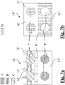
- the planar insert 10' according to the first variant has a uniform thickness and may be conveniently made from a sheet of rigid cardboard or other material suitable for the purpose which is pre-cut as indicated by the broken lines in Figure 7a and glued to the package 1 as indicated by the hatched pattern D shown in Figure 7b .
- the first portion 12' of the planar insert 10' consists in this case of two sub-portions: an engaging sub-portion 7', which is defined in the case in question by two cylindrical buttons and glued directly onto the underlying front wall 2; and a removable sub-portion 14' which is instead not glued to the package 1.
- the second portion 13' has instead two circular windows 8' which are shaped to match the aforementioned cylindrical buttons and which are formed in the underlying rear wall 3.
- the removable sub-portion 14' is joined together with the second portion 13' along the separation line 11'.
- this line is arranged in a zone straddling the front wall 2 and the rear wall 3; in particular, the first planar portion 12' is fixed close to the upper rim of the front wall 2, while the second planar portion 13' is fixed spaced from the upper rim of the respective rear wall 3.
- the removable sub-portion 14' is connected to the engaging sub-portion 7' by means of a separation profile 15' which is also defined, like the separation line 11', by a pre-cut line.
- the user may thus separate, as in the preceding embodiment, the first portion 12' from the second portion 13' along the separation line 11'; then the user may completely detach the removable sub-portion 15' from the engaging sub-portion 7' so as to isolate the two buttons and leave them raised with respect to the underlying front wall 2.
- the user may insert the two raised buttons 7' into the corresponding windows or holes 8', where they are received with an interference fit, thereby defining the releasable connection.
- the form of the engaging sub-portion(s) 7' and the window(s) 8' may be different, while maintaining the convenient solution of using, in an insert of uniform thickness, a removable sub-portion 15' able to free in the reclosing configuration a first element raised with respect to a wall of the package.
- planar insert 10" according to the second variant is similar to that of the first variant: it has in fact a uniform thickness and may be conveniently made from a sheet of rigid cardboard or other material suitable for the purpose, pre-cut as indicated by the broken lines in Figure 8a and glued to the package 1 as indicated by the hatched pattern D shown in Figure 8b .
- the first portion 12" of the planar insert 10" consists in this case also of two sub-portions: an engaging sub-portion 7", which is defined in the case in question by a parallelepiped with one of its long sides convex, glued directly onto the underlying front wall 2; and a removable sub-portion 14" which is instead not glued to the package 1.
- the second portion 13" instead has a window 8" which is formed in the underlying rear wall 3 as a parallelepiped with one of its long sides concave.
- the removable sub-portion 14" is joined together with the second portion 13'" along the separation line 11".
- this line is arranged in a zone straddling the front wall 2 and the rear wall 3; in particular, the first planar portion 12" is fixed close to the upper rim of the front wall 2, while the second planar portion 13" is fixed spaced from the upper rim of the respective rear wall 3.
- the removable sub-portion 14" is also joined here to the engaging sub-portion 7" by means of a separation profile 15" which also is defined by a pre-cut line.
- the engaging sub-portion 7" has a free flap 16" which is not glued and which in the case in question is represented by the convex curvature of the parallelepiped profile; the second portion 13" is instead not glued underneath the curvature which defines the concavity of the window 8", so as to define, between itself and the underlying rear wall 3, a slot 17".
- the user may thus separate, as in the preceding embodiment, the first portion 12" from the second portion 13" along the separation line 11"; then, the user may completely detach the removable sub-portion 15" from the engaging sub-portion 7" so as to leave the latter raised with respect to the underlying front wall 2.
- the user may insert the engaging sub-portion 7" inside the window 8", thus inserting the free flap 16" inside the aforementioned slot 17".
- the form of the engaging sub-portion 7" and the window 8" may be different, while maintaining the convenient solution of providing a free flap of the first element which can be introduced into a slot formed along the perimeter of the second element.
- connection means which are different from the buttons 7 and the holes 8 or the engaging sub-portions 7', 7" and the windows 8', 8" described here: for example successive rows of incisions or teeth designed to engage with correspondingly shaped elements formed on the first planar portion 12, 12', 12" may be provided.
- planar insert 10, 10', 10" which forms the reclosing device is preferably applied after formation, filling and closing of the package 1.
- These operations may therefore be advantageously performed using a conventional packaging line which must not be substantially modified, other than in order to integrate downstream, if required, further stations for folding the closing fin 4 and for applying the planar insert 10, 10', 10".
- the main advantage achieved by the package according to the present invention is that of allowing practical, rapid and efficient reclosing of the said package, which may be repeated a significantly greater number of times than that which is possible with the prior art, while ensuring relatively low production costs.
Landscapes
- Engineering & Computer Science (AREA)
- Mechanical Engineering (AREA)
- Packages (AREA)
- Cartons (AREA)
Priority Applications (4)
| Application Number | Priority Date | Filing Date | Title |
|---|---|---|---|
| PL18204896T PL3486189T3 (pl) | 2017-11-15 | 2018-11-07 | Woreczek do ponownego zamykania |
| RS20201073A RS60771B1 (sr) | 2017-11-15 | 2018-11-07 | Kesa koja se može ponovo zatvoriti |
| SI201830116T SI3486189T1 (sl) | 2017-11-15 | 2018-11-07 | Vreča, ki jo je moč ponovno zapreti |
| HRP20201447TT HRP20201447T1 (hr) | 2017-11-15 | 2020-09-10 | Vreća koja se može ponovo zatvoriti |
Applications Claiming Priority (1)
| Application Number | Priority Date | Filing Date | Title |
|---|---|---|---|
| IT201700130665 | 2017-11-15 |
Publications (2)
| Publication Number | Publication Date |
|---|---|
| EP3486189A1 EP3486189A1 (en) | 2019-05-22 |
| EP3486189B1 true EP3486189B1 (en) | 2020-06-17 |
Family
ID=61527291
Family Applications (1)
| Application Number | Title | Priority Date | Filing Date |
|---|---|---|---|
| EP18204896.7A Active EP3486189B1 (en) | 2017-11-15 | 2018-11-07 | Reclosable bag |
Country Status (12)
| Country | Link |
|---|---|
| US (1) | US10759568B2 (pl) |
| EP (1) | EP3486189B1 (pl) |
| DK (1) | DK3486189T3 (pl) |
| ES (1) | ES2819000T3 (pl) |
| HR (1) | HRP20201447T1 (pl) |
| HU (1) | HUE051770T2 (pl) |
| LT (1) | LT3486189T (pl) |
| PL (1) | PL3486189T3 (pl) |
| PT (1) | PT3486189T (pl) |
| RS (1) | RS60771B1 (pl) |
| RU (1) | RU2769265C2 (pl) |
| SI (1) | SI3486189T1 (pl) |
Family Cites Families (14)
| Publication number | Priority date | Publication date | Assignee | Title |
|---|---|---|---|---|
| IT233249Y1 (it) | 1994-04-13 | 2000-01-26 | Barilla Flli G & R | Etichetta autoadesiva per confezioni da richiudere |
| US6047883A (en) * | 1998-09-08 | 2000-04-11 | Westvaco Corporation | Bagless barrier paperboard container with a tamper evident reclosable fitment |
| EP1326782A2 (en) * | 2000-10-13 | 2003-07-16 | Velcro Industries B.V. | Roll top bag constructions |
| JP4351403B2 (ja) * | 2001-07-23 | 2009-10-28 | 株式会社細川洋行 | ジッパ袋及びその製造方法 |
| US6722784B2 (en) * | 2002-01-22 | 2004-04-20 | Gary L. Breil, Jr. | Snap on envelope |
| US20040223665A1 (en) * | 2003-05-07 | 2004-11-11 | Hudson-Sharp Machine Co. | Reclosable bag |
| US7462313B2 (en) * | 2005-10-12 | 2008-12-09 | Velcro Industries B.V. | Snap closures |
| US7819583B2 (en) * | 2005-11-04 | 2010-10-26 | Graphic Packaging International, Inc. | Bag structures and methods of assembling the same |
| US8641279B2 (en) * | 2006-03-20 | 2014-02-04 | Hosokawa Yoko Co., Ltd. | Packaging bag with fastener |
| US20080056622A1 (en) * | 2006-08-18 | 2008-03-06 | Andrew Austreng | Resealable package with tamper-evident structure and method for making same |
| US20100155279A1 (en) * | 2008-12-23 | 2010-06-24 | Econix Limited | Container constructed substantially from card |
| US20120052161A1 (en) * | 2010-09-01 | 2012-03-01 | Graphic Packaging International, Inc. | Bag With Refastenable Foldover Closure And Pour Spout |
| US9315297B2 (en) * | 2010-11-11 | 2016-04-19 | Ecolean Ab | Resealable opening device and package comprising such an opening device |
| US10562689B2 (en) * | 2012-02-13 | 2020-02-18 | Polytex Fibers Corporation | Woven plastic bags with features that reduce leakage, breakage and infestations |
-
2018
- 2018-11-07 PL PL18204896T patent/PL3486189T3/pl unknown
- 2018-11-07 RS RS20201073A patent/RS60771B1/sr unknown
- 2018-11-07 LT LTEP18204896.7T patent/LT3486189T/lt unknown
- 2018-11-07 RU RU2018139164A patent/RU2769265C2/ru active
- 2018-11-07 PT PT182048967T patent/PT3486189T/pt unknown
- 2018-11-07 DK DK18204896.7T patent/DK3486189T3/da active
- 2018-11-07 SI SI201830116T patent/SI3486189T1/sl unknown
- 2018-11-07 HU HUE18204896A patent/HUE051770T2/hu unknown
- 2018-11-07 EP EP18204896.7A patent/EP3486189B1/en active Active
- 2018-11-07 ES ES18204896T patent/ES2819000T3/es active Active
- 2018-11-12 US US16/186,754 patent/US10759568B2/en active Active
-
2020
- 2020-09-10 HR HRP20201447TT patent/HRP20201447T1/hr unknown
Non-Patent Citations (1)
| Title |
|---|
| None * |
Also Published As
| Publication number | Publication date |
|---|---|
| RU2018139164A3 (pl) | 2022-01-26 |
| RS60771B1 (sr) | 2020-10-30 |
| RU2769265C2 (ru) | 2022-03-29 |
| PL3486189T3 (pl) | 2020-12-14 |
| LT3486189T (lt) | 2020-10-12 |
| DK3486189T3 (da) | 2020-09-07 |
| US20190144167A1 (en) | 2019-05-16 |
| EP3486189A1 (en) | 2019-05-22 |
| ES2819000T3 (es) | 2021-04-14 |
| US10759568B2 (en) | 2020-09-01 |
| SI3486189T1 (sl) | 2020-10-30 |
| HRP20201447T1 (hr) | 2020-12-11 |
| RU2018139164A (ru) | 2020-05-12 |
| PT3486189T (pt) | 2020-08-24 |
| HUE051770T2 (hu) | 2021-03-29 |
Similar Documents
| Publication | Publication Date | Title |
|---|---|---|
| KR100699970B1 (ko) | 재밀폐가능한 용기 설비 | |
| US10611540B2 (en) | Packages having separable sealing features and methods of manufacturing | |
| RU2381969C2 (ru) | Гибкая упаковка с внутренним средством повторного закрывания | |
| US4949527A (en) | Method of forming a reclosable tray | |
| US4896775A (en) | Zippered thermal form tray system | |
| CN102770352B (zh) | 用于食品的可再密封的包装和制造方法 | |
| CN102770353B (zh) | 用于食品的可再密封的包装和制造方法 | |
| US6988828B2 (en) | Closure for containers and reclosable containers including the same | |
| JP2004522659A (ja) | 拡張ガセット付き再閉可能バッグ | |
| AU624488B2 (en) | Zippered closure for thermoformed package | |
| US10017310B2 (en) | Packages having separable sealing features and methods of manufacturing | |
| US20120052161A1 (en) | Bag With Refastenable Foldover Closure And Pour Spout | |
| EP3486190B1 (en) | Reclosable bag | |
| JPH04215954A (ja) | 容易に開放可能な既開封明示型の再閉鎖可能な包装体 | |
| AU2013265394A1 (en) | Package and method for producing the package | |
| US10759568B2 (en) | Flexible packaging of the bag type with reclosing device | |
| RU2781085C2 (ru) | Гибкая упаковка мешочного типа с устройством повторного закрытия | |
| ITMI20140371U1 (it) | Dispositivo di formazione di un'apertura di prelievo richiudibile nella pellicola di una confezione sigillata e confezione-dispensatore | |
| EP1338525A2 (en) | Reclosable packaging | |
| ITMI20131583A1 (it) | Dispositivo di formazione di un'apertura di prelievo richiudibile nella pellicola di una confezione sigillata e confezione-dispensatore |
Legal Events
| Date | Code | Title | Description |
|---|---|---|---|
| PUAI | Public reference made under article 153(3) epc to a published international application that has entered the european phase |
Free format text: ORIGINAL CODE: 0009012 |
|
| STAA | Information on the status of an ep patent application or granted ep patent |
Free format text: STATUS: THE APPLICATION HAS BEEN PUBLISHED |
|
| AK | Designated contracting states |
Kind code of ref document: A1 Designated state(s): AL AT BE BG CH CY CZ DE DK EE ES FI FR GB GR HR HU IE IS IT LI LT LU LV MC MK MT NL NO PL PT RO RS SE SI SK SM TR |
|
| AX | Request for extension of the european patent |
Extension state: BA ME |
|
| STAA | Information on the status of an ep patent application or granted ep patent |
Free format text: STATUS: REQUEST FOR EXAMINATION WAS MADE |
|
| 17P | Request for examination filed |
Effective date: 20191121 |
|
| RBV | Designated contracting states (corrected) |
Designated state(s): AL AT BE BG CH CY CZ DE DK EE ES FI FR GB GR HR HU IE IS IT LI LT LU LV MC MK MT NL NO PL PT RO RS SE SI SK SM TR |
|
| GRAP | Despatch of communication of intention to grant a patent |
Free format text: ORIGINAL CODE: EPIDOSNIGR1 |
|
| STAA | Information on the status of an ep patent application or granted ep patent |
Free format text: STATUS: GRANT OF PATENT IS INTENDED |
|
| RIC1 | Information provided on ipc code assigned before grant |
Ipc: B65D 33/16 20060101AFI20200116BHEP Ipc: B65D 77/14 20060101ALI20200116BHEP Ipc: B65D 33/24 20060101ALI20200116BHEP Ipc: B65D 30/20 20060101ALN20200116BHEP |
|
| INTG | Intention to grant announced |
Effective date: 20200211 |
|
| GRAS | Grant fee paid |
Free format text: ORIGINAL CODE: EPIDOSNIGR3 |
|
| GRAA | (expected) grant |
Free format text: ORIGINAL CODE: 0009210 |
|
| STAA | Information on the status of an ep patent application or granted ep patent |
Free format text: STATUS: THE PATENT HAS BEEN GRANTED |
|
| AK | Designated contracting states |
Kind code of ref document: B1 Designated state(s): AL AT BE BG CH CY CZ DE DK EE ES FI FR GB GR HR HU IE IS IT LI LT LU LV MC MK MT NL NO PL PT RO RS SE SI SK SM TR |
|
| REG | Reference to a national code |
Ref country code: GB Ref legal event code: FG4D |
|
| REG | Reference to a national code |
Ref country code: CH Ref legal event code: EP |
|
| REG | Reference to a national code |
Ref country code: IE Ref legal event code: FG4D |
|
| REG | Reference to a national code |
Ref country code: DE Ref legal event code: R096 Ref document number: 602018005382 Country of ref document: DE |
|
| REG | Reference to a national code |
Ref country code: AT Ref legal event code: REF Ref document number: 1281046 Country of ref document: AT Kind code of ref document: T Effective date: 20200715 |
|
| REG | Reference to a national code |
Ref country code: PT Ref legal event code: SC4A Ref document number: 3486189 Country of ref document: PT Date of ref document: 20200824 Kind code of ref document: T Free format text: AVAILABILITY OF NATIONAL TRANSLATION Effective date: 20200810 |
|
| REG | Reference to a national code |
Ref country code: FI Ref legal event code: FGE |
|
| REG | Reference to a national code |
Ref country code: NO Ref legal event code: T2 Effective date: 20200617 Ref country code: DK Ref legal event code: T3 Effective date: 20200902 |
|
| REG | Reference to a national code |
Ref country code: HR Ref legal event code: TUEP Ref document number: P20201447 Country of ref document: HR |
|
| REG | Reference to a national code |
Ref country code: SE Ref legal event code: TRGR Ref country code: CH Ref legal event code: NV Representative=s name: ING. MARCO ZARDI C/O M. ZARDI AND CO. S.A., CH |
|
| REG | Reference to a national code |
Ref country code: NL Ref legal event code: FP |
|
| REG | Reference to a national code |
Ref country code: EE Ref legal event code: FG4A Ref document number: E019572 Country of ref document: EE Effective date: 20200831 |
|
| REG | Reference to a national code |
Ref country code: GR Ref legal event code: EP Ref document number: 20200402560 Country of ref document: GR Effective date: 20201014 |
|
| REG | Reference to a national code |
Ref country code: HR Ref legal event code: ODRP Ref document number: P20201447 Country of ref document: HR Payment date: 20201023 Year of fee payment: 3 |
|
| REG | Reference to a national code |
Ref country code: SK Ref legal event code: T3 Ref document number: E 35405 Country of ref document: SK |
|
| REG | Reference to a national code |
Ref country code: HR Ref legal event code: T1PR Ref document number: P20201447 Country of ref document: HR |
|
| PG25 | Lapsed in a contracting state [announced via postgrant information from national office to epo] |
Ref country code: SM Free format text: LAPSE BECAUSE OF FAILURE TO SUBMIT A TRANSLATION OF THE DESCRIPTION OR TO PAY THE FEE WITHIN THE PRESCRIBED TIME-LIMIT Effective date: 20200617 |
|
| REG | Reference to a national code |
Ref country code: DE Ref legal event code: R097 Ref document number: 602018005382 Country of ref document: DE |
|
| REG | Reference to a national code |
Ref country code: HU Ref legal event code: AG4A Ref document number: E051770 Country of ref document: HU |
|
| REG | Reference to a national code |
Ref country code: ES Ref legal event code: FG2A Ref document number: 2819000 Country of ref document: ES Kind code of ref document: T3 Effective date: 20210414 |
|
| PLBE | No opposition filed within time limit |
Free format text: ORIGINAL CODE: 0009261 |
|
| STAA | Information on the status of an ep patent application or granted ep patent |
Free format text: STATUS: NO OPPOSITION FILED WITHIN TIME LIMIT |
|
| 26N | No opposition filed |
Effective date: 20210318 |
|
| PG25 | Lapsed in a contracting state [announced via postgrant information from national office to epo] |
Ref country code: MC Free format text: LAPSE BECAUSE OF FAILURE TO SUBMIT A TRANSLATION OF THE DESCRIPTION OR TO PAY THE FEE WITHIN THE PRESCRIBED TIME-LIMIT Effective date: 20200617 |
|
| REG | Reference to a national code |
Ref country code: HR Ref legal event code: ODRP Ref document number: P20201447 Country of ref document: HR Payment date: 20211105 Year of fee payment: 4 |
|
| PG25 | Lapsed in a contracting state [announced via postgrant information from national office to epo] |
Ref country code: CY Free format text: LAPSE BECAUSE OF FAILURE TO SUBMIT A TRANSLATION OF THE DESCRIPTION OR TO PAY THE FEE WITHIN THE PRESCRIBED TIME-LIMIT Effective date: 20200617 |
|
| REG | Reference to a national code |
Ref country code: AT Ref legal event code: UEP Ref document number: 1281046 Country of ref document: AT Kind code of ref document: T Effective date: 20200617 |
|
| REG | Reference to a national code |
Ref country code: HR Ref legal event code: ODRP Ref document number: P20201447 Country of ref document: HR Payment date: 20221104 Year of fee payment: 5 |
|
| P01 | Opt-out of the competence of the unified patent court (upc) registered |
Effective date: 20230520 |
|
| REG | Reference to a national code |
Ref country code: HR Ref legal event code: ODRP Ref document number: P20201447 Country of ref document: HR Payment date: 20231026 Year of fee payment: 6 |
|
| REG | Reference to a national code |
Ref country code: HR Ref legal event code: ODRP Ref document number: P20201447 Country of ref document: HR Payment date: 20241030 Year of fee payment: 7 |
|
| PGFP | Annual fee paid to national office [announced via postgrant information from national office to epo] |
Ref country code: LU Payment date: 20251022 Year of fee payment: 8 Ref country code: NL Payment date: 20251022 Year of fee payment: 8 |
|
| REG | Reference to a national code |
Ref country code: HR Ref legal event code: ODRP Ref document number: P20201447 Country of ref document: HR Payment date: 20251027 Year of fee payment: 8 |
|
| REG | Reference to a national code |
Ref country code: CH Ref legal event code: U11 Free format text: ST27 STATUS EVENT CODE: U-0-0-U10-U11 (AS PROVIDED BY THE NATIONAL OFFICE) Effective date: 20251201 |
|
| PGFP | Annual fee paid to national office [announced via postgrant information from national office to epo] |
Ref country code: PT Payment date: 20251024 Year of fee payment: 8 |
|
| PGFP | Annual fee paid to national office [announced via postgrant information from national office to epo] |
Ref country code: HU Payment date: 20251117 Year of fee payment: 8 |
|
| PGFP | Annual fee paid to national office [announced via postgrant information from national office to epo] |
Ref country code: IS Payment date: 20251107 Year of fee payment: 8 Ref country code: DE Payment date: 20251022 Year of fee payment: 8 |
|
| PGFP | Annual fee paid to national office [announced via postgrant information from national office to epo] |
Ref country code: LT Payment date: 20251022 Year of fee payment: 8 Ref country code: GB Payment date: 20251023 Year of fee payment: 8 |
|
| PGFP | Annual fee paid to national office [announced via postgrant information from national office to epo] |
Ref country code: NO Payment date: 20251024 Year of fee payment: 8 |
|
| PGFP | Annual fee paid to national office [announced via postgrant information from national office to epo] |
Ref country code: MK Payment date: 20251027 Year of fee payment: 8 Ref country code: AT Payment date: 20251024 Year of fee payment: 8 |
|
| PGFP | Annual fee paid to national office [announced via postgrant information from national office to epo] |
Ref country code: FI Payment date: 20251022 Year of fee payment: 8 Ref country code: DK Payment date: 20251022 Year of fee payment: 8 Ref country code: IT Payment date: 20251118 Year of fee payment: 8 |
|
| PGFP | Annual fee paid to national office [announced via postgrant information from national office to epo] |
Ref country code: HR Payment date: 20251027 Year of fee payment: 8 Ref country code: FR Payment date: 20251022 Year of fee payment: 8 |
|
| PGFP | Annual fee paid to national office [announced via postgrant information from national office to epo] |
Ref country code: AL Payment date: 20251121 Year of fee payment: 8 Ref country code: BE Payment date: 20251022 Year of fee payment: 8 Ref country code: GR Payment date: 20251024 Year of fee payment: 8 Ref country code: TR Payment date: 20251031 Year of fee payment: 8 |
|
| PGFP | Annual fee paid to national office [announced via postgrant information from national office to epo] |
Ref country code: CH Payment date: 20251201 Year of fee payment: 8 Ref country code: SE Payment date: 20251022 Year of fee payment: 8 |
|
| PGFP | Annual fee paid to national office [announced via postgrant information from national office to epo] |
Ref country code: IE Payment date: 20251024 Year of fee payment: 8 Ref country code: CZ Payment date: 20251030 Year of fee payment: 8 |
|
| PGFP | Annual fee paid to national office [announced via postgrant information from national office to epo] |
Ref country code: LV Payment date: 20251022 Year of fee payment: 8 Ref country code: MT Payment date: 20251029 Year of fee payment: 8 |
|
| PGFP | Annual fee paid to national office [announced via postgrant information from national office to epo] |
Ref country code: BG Payment date: 20251028 Year of fee payment: 8 Ref country code: PL Payment date: 20251023 Year of fee payment: 8 |
|
| PGFP | Annual fee paid to national office [announced via postgrant information from national office to epo] |
Ref country code: EE Payment date: 20251028 Year of fee payment: 8 |
|
| PGFP | Annual fee paid to national office [announced via postgrant information from national office to epo] |
Ref country code: SK Payment date: 20251029 Year of fee payment: 8 Ref country code: RO Payment date: 20251105 Year of fee payment: 8 |
|
| PGFP | Annual fee paid to national office [announced via postgrant information from national office to epo] |
Ref country code: RS Payment date: 20251028 Year of fee payment: 8 |
|
| PGFP | Annual fee paid to national office [announced via postgrant information from national office to epo] |
Ref country code: SI Payment date: 20251029 Year of fee payment: 8 Ref country code: ES Payment date: 20251201 Year of fee payment: 8 |