EP3486126B1 - Webbing adjustment device - Google Patents
Webbing adjustment device Download PDFInfo
- Publication number
- EP3486126B1 EP3486126B1 EP18196275.4A EP18196275A EP3486126B1 EP 3486126 B1 EP3486126 B1 EP 3486126B1 EP 18196275 A EP18196275 A EP 18196275A EP 3486126 B1 EP3486126 B1 EP 3486126B1
- Authority
- EP
- European Patent Office
- Prior art keywords
- webbing
- plate portion
- adjustment device
- cover
- guiding ring
- Prior art date
- Legal status (The legal status is an assumption and is not a legal conclusion. Google has not performed a legal analysis and makes no representation as to the accuracy of the status listed.)
- Active
Links
Images






Classifications
-
- B—PERFORMING OPERATIONS; TRANSPORTING
- B60—VEHICLES IN GENERAL
- B60R—VEHICLES, VEHICLE FITTINGS, OR VEHICLE PARTS, NOT OTHERWISE PROVIDED FOR
- B60R22/00—Safety belts or body harnesses in vehicles
- B60R22/18—Anchoring devices
- B60R22/26—Anchoring devices secured to the seat
-
- B—PERFORMING OPERATIONS; TRANSPORTING
- B60—VEHICLES IN GENERAL
- B60R—VEHICLES, VEHICLE FITTINGS, OR VEHICLE PARTS, NOT OTHERWISE PROVIDED FOR
- B60R22/00—Safety belts or body harnesses in vehicles
- B60R22/02—Semi-passive restraint systems, e.g. systems applied or removed automatically but not both ; Manual restraint systems
- B60R22/023—Three-point seat belt systems comprising two side lower and one side upper anchoring devices
- B60R22/024—Adaptations for use by small passengers, e.g. children
-
- A—HUMAN NECESSITIES
- A44—HABERDASHERY; JEWELLERY
- A44B—BUTTONS, PINS, BUCKLES, SLIDE FASTENERS, OR THE LIKE
- A44B11/00—Buckles; Similar fasteners for interconnecting straps or the like, e.g. for safety belts
- A44B11/25—Buckles; Similar fasteners for interconnecting straps or the like, e.g. for safety belts with two or more separable parts
- A44B11/2503—Safety buckles
- A44B11/2546—Details
- A44B11/2553—Attachment of buckle to strap
- A44B11/2557—Attachment of buckle to strap with strap length adjustment
-
- B—PERFORMING OPERATIONS; TRANSPORTING
- B60—VEHICLES IN GENERAL
- B60R—VEHICLES, VEHICLE FITTINGS, OR VEHICLE PARTS, NOT OTHERWISE PROVIDED FOR
- B60R22/00—Safety belts or body harnesses in vehicles
- B60R22/02—Semi-passive restraint systems, e.g. systems applied or removed automatically but not both ; Manual restraint systems
- B60R22/023—Three-point seat belt systems comprising two side lower and one side upper anchoring devices
-
- B—PERFORMING OPERATIONS; TRANSPORTING
- B60—VEHICLES IN GENERAL
- B60R—VEHICLES, VEHICLE FITTINGS, OR VEHICLE PARTS, NOT OTHERWISE PROVIDED FOR
- B60R22/00—Safety belts or body harnesses in vehicles
- B60R22/10—Safety belts or body harnesses in vehicles specially adapted for children or animals
- B60R22/105—Safety belts or body harnesses in vehicles specially adapted for children or animals for children
-
- B—PERFORMING OPERATIONS; TRANSPORTING
- B60—VEHICLES IN GENERAL
- B60R—VEHICLES, VEHICLE FITTINGS, OR VEHICLE PARTS, NOT OTHERWISE PROVIDED FOR
- B60R22/00—Safety belts or body harnesses in vehicles
- B60R22/18—Anchoring devices
- B60R22/19—Anchoring devices with means for reducing belt tension during use under normal conditions
-
- B—PERFORMING OPERATIONS; TRANSPORTING
- B60—VEHICLES IN GENERAL
- B60R—VEHICLES, VEHICLE FITTINGS, OR VEHICLE PARTS, NOT OTHERWISE PROVIDED FOR
- B60R22/00—Safety belts or body harnesses in vehicles
- B60R22/18—Anchoring devices
- B60R22/20—Anchoring devices adjustable in position, e.g. in height
-
- B—PERFORMING OPERATIONS; TRANSPORTING
- B60—VEHICLES IN GENERAL
- B60R—VEHICLES, VEHICLE FITTINGS, OR VEHICLE PARTS, NOT OTHERWISE PROVIDED FOR
- B60R22/00—Safety belts or body harnesses in vehicles
- B60R22/18—Anchoring devices
- B60R2022/1818—Belt guides
Definitions
- the present invention relates to a webbing adjustment device, and more particularly to a webbing adjustment device to adjust a height of an upper area of a three-point seat belt system of a vehicle.
- each vehicle has to install a seat belt system.
- a retractor of the seat belt system is disposed on a support pillar in the vehicle and is located beside a seat in the vehicle.
- a webbing of the seat belt system is pulled out from the retractor of the seat belt system.
- the webbing of the seat belt system is passed through a guiding ring of the seat belt system, and then the webbing is obliquely passed the front of the occupant's torso.
- a tongue mounted around the webbing is inserted into a buckle mounted on the seat of the vehicle.
- a section of the webbing passes through the tongue and extends to a side of the seat near the retractor to form a three-point seat belt system.
- the body of the occupant in the vehicle is restrained on the seat in the vehicle by the webbing.
- a conventional height adjustment device for the webbing of the seat belt system is adapted to a specific vehicle and has some defects, such as complex structure, short range of adjustment, multi-step adjustment, and complicated operation. Thus, it is necessary to invent a simplified, convenient, and useful height adjustment device to adjust the height of the webbing near the shoulder of the occupant in the vehicle.
- Document US2017/267209 A1 discloses a webbing adjustment device being applied to connect to a webbing of a seat belt system, wherein the device comprising: a cover; having a base having two side surfaces; a back surface formed in the base, located between the two side surfaces of the base, and having a top section; and at least one stop portion formed on the bottom section section of the back surface of the base; two side plates respectively formed on the two side surfaces of the base, protruded out of the back surface of the bas, and being opposite to each other, and each one of the two side plates having a top surface; a bottom surface and an inner surface.
- the objective of the invention is to provide a webbing adjustment device that can solve the problems of the conventional height adjustment device including complex structure, short range of adjustment, multi-step adjustment, and complicated operation.
- the webbing adjustment device is applied to connect to a webbing of a seat belt system.
- the webbing adjustment device has a cover, a frame, a slider, and a guiding ring member.
- the cover has a base, two side plates, and a space.
- the base has two side surfaces, a back surface, and at least one stop portion.
- the back surface is formed in the base, is located between the two side surfaces of the base, and has a top section.
- the at least one stop portion is formed on the top section of the back surface of the base.
- the two side plates are respectively formed on the two side surfaces of the base, are protruded out of the back surface of the base, and are opposite to each other.
- Each one of the two side plates has a top surface, a bottom surface, an inner surface, a guiding groove, a first retaining portion, a connecting groove, and a second retaining portion.
- the guiding groove is formed on the inner surface of the side plate, extends to the top surface of the side plate, and has a bottom.
- the first retaining portion is formed on the inner surface of the side plate and is located at the bottom of the guiding groove.
- the connecting groove is formed on the inner surface of the side plate, extends to the bottom surface of the side plate, and has a top.
- the second retaining portion is formed on the inner surface of the side plate and is located at the top of the connecting groove.
- the space is formed in the cover adjacent to the back surface of the base and is located between the two side plates.
- the back surface of the base faces the space of the cover.
- the inner surface of each one of the side plates faces the space of the cover.
- the frame is up and down moveably disposed in the cover, and has a bottom end, two sides, a through hole, and two longitudinal portions.
- the through hole is formed through the body.
- the two longitudinal portions are respectively formed on the two sides of the body.
- the two longitudinal portions are up and down slidably inserted into the guiding grooves of the two side plates, respectively.
- the connecting portion is formed on the bottom end of the body, and has a connecting hole formed through the connecting portion.
- the connecting portion is connected to a section of the webbing.
- the slider is located in the cover, is moveably disposed in the body of the frame, and has a first plate portion, a second plate portion, a through portion, and a through slot.
- the first plate portion is located between the base and the body, and is disposed below the at least one stop portion of the base.
- the second plate portion is opposite to the first plate portion.
- the through portion is formed between the first plate portion and the second plate portion.
- the through slot is formed through the through portion. Another section of the webbing is inserted through the through slot. The section of the webbing inserted through the through slot is locked or unlocked by a relative motion between the frame and the slider.
- the guiding ring member is detachably disposed on the cover and has a guiding ring and a positioning element.
- the guiding ring has two sides and a top end.
- the webbing is inserted through the guiding ring.
- the cover is detachably hung on the guiding ring.
- the two sides of the guiding ring are respectively inserted into the connecting grooves of the two side plates.
- the second retaining portion of the two side plates are hung on the guiding ring.
- the positioning element is connected to the top end of the guiding ring.
- the webbing adjustment device is applied to the seat belt system in a vehicle.
- the guiding ring member is fixedly disposed on a support pillar in the vehicle and is located beside a seat in the vehicle.
- the webbing of the seat belt system is passed through the guiding ring of the guiding ring member.
- the frame and the slider moveably assembled in the cover are connected to two sections of the webbing divided by the guiding ring.
- the cover may be hung on the guiding ring to position the cover.
- the frame and the slider assembled in the cover are unlocked. The webbing can be pulled freely.
- the cover When the height position of a positioning point on the webbing needs adjusting, the cover is detached from the guiding ring member and is held by an occupant.
- the cover can move upwardly or downwardly in an intuitive way for adjusting the height position of the positioning point on the webbing.
- the relative motion between the frame and the slider is generated to unlock the webbing.
- the height position of the positioning point is adjusted steplessly.
- the webbing adjustment device may be moved to a suitable position, the cover can be released.
- the webbing adjustment device locks the webbing automatically by the tension of the webbing for ensuring that the positioning point of the webbing is close to the height of the shoulder of the occupant.
- the webbing adjustment device is adapted to various types of vehicles.
- the webbing adjustment device is simplified in structure, easy in operation, and cost-effective in manufacture and assembly.
- the webbing adjustment device can be adjusted steplessly.
- the adjustment range of the webbing adjustment device is long.
- the webbing adjustment device is easy to operate and automatically locks the webbing.
- the guiding ring is made of magnetic materials, and the cover has two magnets.
- the two magnets are respectively disposed on the two side plates for attracting the guiding ring.
- the magnets on the cover can attract the guiding ring for increasing the positioning stability.
- a first embodiment and a second embodiment of a webbing adjustment device 1 in accordance with the present invention each comprise a cover 10, a frame 20, and a slider 30. Furthermore, the second embodiment of the webbing adjustment device further comprises a guiding ring member 40.
- the cover 10 has a base 11, two side plates 12, and a space 100.
- the base 11 has two side surfaces, a back surface 111, and at least one stop portion 13.
- the back surface 111 is formed in the base 11, is located between the two side surfaces of the base 11, and has a top section.
- the at least one stop portion 13 is formed on the top section of the back surface 111 of the base 11.
- the two side plates 12 are respectively formed on the two side surfaces of the base 11, are protruded out of the back surface 111 of the base 11, and are opposite to each other.
- Each one of the two side plates 12 has a top surface, a bottom surface, an inner surface 121, a guiding groove 14, a first retaining portion 15, a connecting groove 16, and a second retaining portion 17.
- the guiding groove 14 is formed on the inner surface 121 of the side plate 12, extends to the top surface of the side plate 12, and has a bottom.
- the first retaining portion 15 is formed on the inner surface 121 of the side plate 12 and is located at the bottom of the guiding groove 14.
- the connecting groove 16 is formed on the inner surface 121 of the side plate 12, extends to the bottom surface of the side plate 12, and has a top.
- the second retaining portion 17 is formed on the inner surface 121 of the side plate 12 and is located at the top of the connecting groove 16.
- the space 100 is formed in the cover 10 adjacent to the back surface 111 of the base 11 and is located between the two side plates 12.
- the back surface 111 of the base 11 faces the space 100 of the cover 10.
- the inner surface 121 of each one of the side plates 12 faces the space 100 of the cover 10.
- the cover 10 has two magnets 18.
- the two magnets 18 are respectively disposed on the two side plates 12, and are disposed adjacent to the tops of the two connecting grooves 16 respectively.
- the frame 20 is up and down moveably disposed in the cover 10, and has a body 21 and a connecting portion 22.
- the body 21 is up and down moveably disposed in the cover 10, and has a bottom end, two sides, a through hole 211, and two longitudinal portions 212.
- the through hole 211 is formed through the body 21.
- the two longitudinal portions 212 are respectively formed on the two sides of the body 21.
- the two longitudinal portions 212 are up and down slidably inserted into the guiding grooves 14 of the two side plates 12 slidably, respectively, and are limited by the first retaining portions 15 of the two side plates 12.
- the connecting portion 22 is formed on the bottom end of the body 21 and has a connecting hole 221 formed through the connecting portion 22.
- the connecting hole 221 is a close-type hole and is located in the connecting portion 22.
- the connecting hole 221 is formed through the connecting portion 22 and is an open-type hole.
- the connecting portion 22 is connected to a section of the webbing 2.
- the webbing 2 may be directly passed through the connecting hole 221 of the connecting portion 22.
- the webbing adjustment device has a connecting strap 23 and a connecting element 24.
- the connecting strap 23 is flexible and is connected to the connecting portion 22.
- the connecting element 24 is connected to the connecting strap 23.
- the webbing 2 is inserted through the connecting element 24. Therefore, the connecting portion 22 of the frame 20 is indirectly connected to the webbing 2 by the connecting strap 23 and the connecting element 24 in series connection.
- the connecting strap 23 is a strap having elasticity or no elasticity.
- the slider 30 is located in the space 100 of the cover 10 and is moveably disposed in the body 21 of the frame 20.
- the slider 30 can move relative to the frame 20.
- the slider 30 has a first plate portion 31, a second plate portion 32, a through portion 33, and a through slot 331.
- the first plate portion 31 is located between the base 11 and the body 21, and is disposed below the at least one stop portion 13 of the base 11.
- the second plate portion 32 is disposed opposite to the first plate portion 31.
- the through portion 33 is formed between the first plate portion 31 and the second plate portion 32.
- the through slot 331 is formed through the through portion 33.
- the through portion 33 has two side walls 332 and two slide slots 34.
- Each one of the two side walls 332 is connected to the first plate portion 31 and the second plate portion 32, and has an outer surface.
- the through slot 331 is located between the two side walls 332.
- the two slide slots 34 are respectively formed on the outer surfaces of the two side walls 332 and extend from top to bottom along the side walls 332. Each one of the two slide slots 34 is located between the first plate portion 31 and the second plate portion 32.
- the through portion 33 of the slider 30 is passed through the through hole 211 of the body 21 of the frame 20.
- the first plate portion 31 and the second plate portion 32 of the slider 30 are located at two opposite sides of the frame 20.
- the first plate portion 31 faces the back surface 111 of the base 11 of the cover 10.
- the two longitudinal portions 212 of the body 21 are respectively inserted into the two slide slots 34 of the through portion 33.
- the through portion 33 of the slider 30 is limited by the through hole 211 of the body 21.
- the slider 30 moves in a limited range defined between the body 21 of the frame 20 and the cover 10.
- the first plate portion 31 has a top surface, a bottom section, and a bottom end.
- the second plate portion 32 has a top surface, a top section, and a top end.
- the top surface of the first plate portion 31 is higher than the top surface of the second plate portion 32.
- the through portion 33 of the slider 30 is formed between the bottom section of the first plate portion 31 and the top section of the second plate portion 32.
- the through slot 331 is sloped from the top end of the second plate portion 32 toward the bottom end of the first plate portion 31.
- the second plate portion 32 has a protruding portion 321.
- the protruding portion 321 is formed on the top surface of the second plate portion 32.
- the slider 30 is assembled on the frame 20 for moving relative to the frame 20 in the cover 10.
- the at least one stop portion 13 formed on the top section of the back surface 111 of the base 11 of the cover 10 is located above the first plate portion 31 of the slider 30.
- the guiding ring member 40 is detachably disposed on the cover 10.
- the guiding ring member 40 has a guiding ring 41 and a positioning element 42.
- the guiding ring 41 has two sides and a top end.
- the guiding ring 41 is made of magnetic materials and can be magnetically attracted.
- the positioning element 42 is connected to the top end of the guiding ring 41.
- the webbing 2 is inserted through the guiding ring 41.
- the cover 10 assembled with the frame 20 and the slider 30 is detachably hung on the guiding ring 41 from top to bottom.
- the two sides of the guiding ring 41 are respectively inserted into the connecting grooves 16 of the two side plates 12.
- the second retaining portions 17 abut against the top end of the guiding ring 41 for assembling the guiding ring 41 in the cover 10.
- the cover 10 assembled with the frame 20 and the slider 30 can move upwardly for detaching the cover 10 assembled with the frame 20 and the slider 30 from the guiding ring 41.
- the webbing adjustment device 1 is applied to the seat belt system mounted in a vehicle.
- the positioning element 42 of the guiding ring member 40 is fixedly mounted on the pillar of the vehicle by a fixing element for fixing the webbing adjustment device beside a seat in the vehicle.
- the webbing 2 is pulled from a retractor 3 located beside the seat and is passed through the connecting portion 22 of the frame 20.
- the webbing 2 is passed through the guiding ring 41 of the guiding ring member 40 and the through slot 331 of the slider 30 located in the frame 20.
- the webbing 2 has a front section 2A and a rear section 2B.
- the front section 2A of the webbing 2 is defined between the guiding ring 41 and the retractor 3.
- the rear section 2B of the webbing 2 is connected to the front section 2A of the webbing 2 and is sequentially passed through the guiding ring 41, the cover 10, the frame 20, the slider 3, and a tongue 4.
- a height of a positioning point of the webbing adjustment device 1 on the webbing 2 can be adjusted by the occupant.
- the cover 10 can be held by one hand of the occupant for driving the frame 20 or the slider 30.
- the relative motion between the frame 20 and the slider 30 is generated to unlock the rear section 2B of the webbing 2. Furthermore, the cover 10 can be pushed upwardly or pulled downwardly by the occupant with stepless adjustment.
- the webbing adjustment device 1 moves to a suitable position, the webbing adjustment device 1 can be released by the occupant. Under the tension of webbing 2, the frame 20 and the slider 30 relatively move to secure the rear section 2B of the webbing 2, and the webbing adjustment device 1 generates sufficient friction to lock the webbing 2 automatically. Then, the rear section 2B of the webbing 2 between the tongue 4 and the guiding ring 41 is not allowed to move relative to the webbing adjustment device 1.
- the webbing adjustment device 1 is moved upward by the occupant to adjust the height of the webbing adjustment device 1.
- the cover 10 is pushed upward by the occupant.
- the frame 20 is pushed upward by the first retaining portions 15 of the two side plates 12 of the cover 10.
- the cover 10 drives the frame 20 to move upward relative to the slider 30.
- the detachment of the cover 10 is avoided.
- the frame 20 and the slider 30 do not generate sufficient force to secure the rear section 2B of the webbing 2.
- the webbing adjustment device 1 can be moved upward relative to the rear section 2B of the webbing 2.
- the webbing adjustment device 1 is moved downwardly by the occupant to adjust the height of the webbing adjustment device 1.
- the cover 10 is pulled downwardly by the occupant.
- the slider 30 is pressed downward by the at least one stop portion 13 of the base 11 of the cover 10.
- the slider 30 is moved downward relative to the frame 20 by the cover 10. Furthermore, the frame 20 and the slider 30 do not generate sufficient force to secure the rear section 2B of the webbing 2.
- the webbing adjustment device 1 can be moved downward relative to the rear section 2B of the webbing 2.
- the cover 10 when the webbing adjustment device 1 is not in use, the cover 10 may be hung on the guiding ring 41 to position the cover 10 on the guiding ring 41.
- the frame 20 and the slider 30 assembled in the cover 10 are unlocked relative to the webbing 2.
- the webbing 2 can be pulled freely.
- the magnets 18 on the two side plates 12 of the cover 10 can attract the guiding ring 41 having magnetic conductivity for increasing the positioning stability.
- the connecting portion 22 of the frame 20 is connected to the connecting element 24 by the connecting strap 23 having flexibility.
- the webbing 2 is pulled from the retractor 3 located beside the seat and is passed through the connecting element 24.
- the webbing 2 is passed through the guiding ring 41 of the guiding ring member 40 and the through slot 331 of the slider 30 located in the frame 20.
- the assembly and the operation of the second embodiment of the webbing adjustment device are substantially identical with those of the first embodiment and detailed descriptions thereof are omitted.
- the webbing adjustment device 1 is applied to the seat belt system and is located between the front section 2A and the rear section 2B below the guiding ring 41.
- the rear section 2B can pass through the webbing adjustment device 1.
- the positioning point of the webbing 2 near the guiding ring member 40 is restricted by the webbing adjustment device 1 for protecting the occupant's neck from slashing by the webbing 2.
- the relative motion between the frame 20 and the slider 30 is generated to unlock the webbing 2.
- the webbing adjustment device 1 may be moved upwardly and downwardly to a suitable position by the occupant in an intuitive way, and then can be released.
- the webbing adjustment device 1 locks the webbing 2 automatically at desired positioning point by the tension of the webbing 2 for ensuring that the positioning point of the webbing 2 is close to the height of the shoulder of the occupant. Therefore, the webbing is prevented from rubbing the neck of the occupant.
- the webbing adjustment device 1 is adapted to various types of vehicles.
- the webbing adjustment device 1 is simplified in structure, easy in operation, and cost-effective in manufacture and assembly.
- the webbing adjustment device 1 has advantages that the webbing adjustment device 1 can be adjusted steplessly, the adjustment range of the webbing adjustment device 1 is long, and the webbing adjustment device 1 is easy to operate and automatically locks the webbing 2.
Landscapes
- Engineering & Computer Science (AREA)
- Mechanical Engineering (AREA)
- Automotive Seat Belt Assembly (AREA)
- Buckles (AREA)
Description
- The present invention relates to a webbing adjustment device, and more particularly to a webbing adjustment device to adjust a height of an upper area of a three-point seat belt system of a vehicle.
- For protecting every occupant in a vehicle, each vehicle has to install a seat belt system. In general, a retractor of the seat belt system is disposed on a support pillar in the vehicle and is located beside a seat in the vehicle. A webbing of the seat belt system is pulled out from the retractor of the seat belt system. The webbing of the seat belt system is passed through a guiding ring of the seat belt system, and then the webbing is obliquely passed the front of the occupant's torso. A tongue mounted around the webbing is inserted into a buckle mounted on the seat of the vehicle. A section of the webbing passes through the tongue and extends to a side of the seat near the retractor to form a three-point seat belt system. The body of the occupant in the vehicle is restrained on the seat in the vehicle by the webbing.
- In a conventional three-point seat belt system, when the webbing is fastened tightly, the height of the webbing near the shoulder of the occupant cannot be adjusted. In emergency, the neck of the occupant may be slashed by the webbing. The height of the webbing can be adjusted by a height adjustment device for the webbing. Therefore, with increasing awareness on vehicle safety, the height adjustment device for the webbing of the seat belt system is necessary.
- A conventional height adjustment device for the webbing of the seat belt system is adapted to a specific vehicle and has some defects, such as complex structure, short range of adjustment, multi-step adjustment, and complicated operation. Thus, it is necessary to invent a simplified, convenient, and useful height adjustment device to adjust the height of the webbing near the shoulder of the occupant in the vehicle.
- To overcome the shortcomings, the present invention provides a webbing adjustment device for a seat belt system to mitigate or obviate the aforementioned problems. Document
US2017/267209 A1 discloses a webbing adjustment device being applied to connect to a webbing of a seat belt system, wherein the device comprising: a cover; having a base having two side surfaces; a back surface formed in the base, located between the two side surfaces of the base, and having a top section; and at least one stop portion formed on the bottom section section of the back surface of the base; two side plates respectively formed on the two side surfaces of the base, protruded out of the back surface of the bas, and being opposite to each other, and each one of the two side plates having a top surface; a bottom surface and an inner surface. - The objective of the invention is to provide a webbing adjustment device that can solve the problems of the conventional height adjustment device including complex structure, short range of adjustment, multi-step adjustment, and complicated operation.
- The webbing adjustment device is applied to connect to a webbing of a seat belt system. The webbing adjustment device has a cover, a frame, a slider, and a guiding ring member.
- The cover has a base, two side plates, and a space. The base has two side surfaces, a back surface, and at least one stop portion. The back surface is formed in the base, is located between the two side surfaces of the base, and has a top section. The at least one stop portion is formed on the top section of the back surface of the base. The two side plates are respectively formed on the two side surfaces of the base, are protruded out of the back surface of the base, and are opposite to each other. Each one of the two side plates has a top surface, a bottom surface, an inner surface, a guiding groove, a first retaining portion, a connecting groove, and a second retaining portion. The guiding groove is formed on the inner surface of the side plate, extends to the top surface of the side plate, and has a bottom. The first retaining portion is formed on the inner surface of the side plate and is located at the bottom of the guiding groove. The connecting groove is formed on the inner surface of the side plate, extends to the bottom surface of the side plate, and has a top. The second retaining portion is formed on the inner surface of the side plate and is located at the top of the connecting groove. The space is formed in the cover adjacent to the back surface of the base and is located between the two side plates. The back surface of the base faces the space of the cover. The inner surface of each one of the side plates faces the space of the cover.
- The frame is up and down moveably disposed in the cover, and has a bottom end, two sides, a through hole, and two longitudinal portions. The through hole is formed through the body. The two longitudinal portions are respectively formed on the two sides of the body. The two longitudinal portions are up and down slidably inserted into the guiding grooves of the two side plates, respectively. The connecting portion is formed on the bottom end of the body, and has a connecting hole formed through the connecting portion. The connecting portion is connected to a section of the webbing.
- The slider is located in the cover, is moveably disposed in the body of the frame, and has a first plate portion, a second plate portion, a through portion, and a through slot. The first plate portion is located between the base and the body, and is disposed below the at least one stop portion of the base. The second plate portion is opposite to the first plate portion. The through portion is formed between the first plate portion and the second plate portion. The through slot is formed through the through portion. Another section of the webbing is inserted through the through slot. The section of the webbing inserted through the through slot is locked or unlocked by a relative motion between the frame and the slider.
- The guiding ring member is detachably disposed on the cover and has a guiding ring and a positioning element. The guiding ring has two sides and a top end. The webbing is inserted through the guiding ring. The cover is detachably hung on the guiding ring. The two sides of the guiding ring are respectively inserted into the connecting grooves of the two side plates. The second retaining portion of the two side plates are hung on the guiding ring. The positioning element is connected to the top end of the guiding ring.
- The webbing adjustment device is applied to the seat belt system in a vehicle. The guiding ring member is fixedly disposed on a support pillar in the vehicle and is located beside a seat in the vehicle. The webbing of the seat belt system is passed through the guiding ring of the guiding ring member. The frame and the slider moveably assembled in the cover are connected to two sections of the webbing divided by the guiding ring. When the webbing adjustment device is not in use, or a height position of a positioning point on the webbing does not need adjusting, the cover may be hung on the guiding ring to position the cover. The frame and the slider assembled in the cover are unlocked. The webbing can be pulled freely.
- When the height position of a positioning point on the webbing needs adjusting, the cover is detached from the guiding ring member and is held by an occupant. The cover can move upwardly or downwardly in an intuitive way for adjusting the height position of the positioning point on the webbing. The relative motion between the frame and the slider is generated to unlock the webbing. The height position of the positioning point is adjusted steplessly. When the webbing adjustment device may be moved to a suitable position, the cover can be released. The webbing adjustment device locks the webbing automatically by the tension of the webbing for ensuring that the positioning point of the webbing is close to the height of the shoulder of the occupant. The webbing adjustment device is adapted to various types of vehicles. The webbing adjustment device is simplified in structure, easy in operation, and cost-effective in manufacture and assembly. The webbing adjustment device can be adjusted steplessly. The adjustment range of the webbing adjustment device is long. The webbing adjustment device is easy to operate and automatically locks the webbing.
- The guiding ring is made of magnetic materials, and the cover has two magnets. The two magnets are respectively disposed on the two side plates for attracting the guiding ring. When the cover is hung on the guiding ring for positioning, the magnets on the cover can attract the guiding ring for increasing the positioning stability.
-
-
Fig. 1 is a perspective view of a first embodiment of a webbing adjustment device in accordance with the present invention; -
Fig. 2 is a perspective view of a second embodiment of a webbing adjustment device in accordance with the present invention, showing a connecting strap and a connecting element are disposed on the webbing adjustment device; -
Fig. 3 is an exploded perspective view of the webbing adjustment device inFig. 1 ; -
Fig. 4 is another exploded perspective view of the webbing adjustment device inFig. 1 ; -
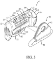
Fig. 5 is another exploded perspective view of the webbing adjustment device inFig. 1 , showing a guiding ring member is detached from the webbing adjustment device; -
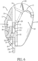
Fig. 6 is a front side view in partial section of the webbing adjustment device inFig. 1 , showing a cover, a frame, and a slider are assembled; -
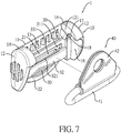
Fig. 7 is an exploded perspective view of a third embodiment of a webbing adjustment device in accordance with the present invention; -
Fig. 8 is an operational front side view of the webbing adjustment device inFig. 1 , showing the webbing adjustment device is assembled on a seat belt system; -
Fig. 9 is an enlarged and operational front side view in partial section of the webbing adjustment device inFig. 8 ; -
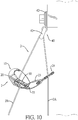
Fig. 10 is an enlarged and operational front side view in partial section of the webbing adjustment device inFig. 2 , showing the webbing adjustment device is assembled on the seat belt system; -
Fig. 11 is an operational front side view in partial section of the webbing adjustment device inFig. 9 , showing the webbing adjustment is in an unlocked state; -
Fig. 12 is an operational front side view in partial section of the webbing adjustment device inFig. 9 , showing the webbing adjustment device moves downwardly; and -
Fig. 13 is an operational front side view in partial section of the webbing adjustment device inFig. 9 , showing the cover is assembled on a guiding ring member. - With reference to
Figs. 1 and2 , a first embodiment and a second embodiment of a webbing adjustment device 1 in accordance with the present invention each comprise acover 10, aframe 20, and aslider 30. Furthermore, the second embodiment of the webbing adjustment device further comprises a guidingring member 40. - With reference to
Figs. 3 to 6 , thecover 10 has abase 11, twoside plates 12, and aspace 100. Thebase 11 has two side surfaces, aback surface 111, and at least onestop portion 13. Theback surface 111 is formed in thebase 11, is located between the two side surfaces of thebase 11, and has a top section. The at least onestop portion 13 is formed on the top section of theback surface 111 of thebase 11. - The two
side plates 12 are respectively formed on the two side surfaces of thebase 11, are protruded out of theback surface 111 of thebase 11, and are opposite to each other. Each one of the twoside plates 12 has a top surface, a bottom surface, aninner surface 121, a guidinggroove 14, a first retainingportion 15, a connectinggroove 16, and asecond retaining portion 17. The guidinggroove 14 is formed on theinner surface 121 of theside plate 12, extends to the top surface of theside plate 12, and has a bottom. Thefirst retaining portion 15 is formed on theinner surface 121 of theside plate 12 and is located at the bottom of the guidinggroove 14. The connectinggroove 16 is formed on theinner surface 121 of theside plate 12, extends to the bottom surface of theside plate 12, and has a top. Thesecond retaining portion 17 is formed on theinner surface 121 of theside plate 12 and is located at the top of the connectinggroove 16. - The
space 100 is formed in thecover 10 adjacent to theback surface 111 of thebase 11 and is located between the twoside plates 12. Theback surface 111 of the base 11 faces thespace 100 of thecover 10. Theinner surface 121 of each one of theside plates 12 faces thespace 100 of thecover 10. - With reference to
Fig. 7 , thecover 10 has twomagnets 18. The twomagnets 18 are respectively disposed on the twoside plates 12, and are disposed adjacent to the tops of the two connectinggrooves 16 respectively. - With reference to
Figs. 3 to 6 , theframe 20 is up and down moveably disposed in thecover 10, and has abody 21 and a connectingportion 22. Thebody 21 is up and down moveably disposed in thecover 10, and has a bottom end, two sides, a throughhole 211, and twolongitudinal portions 212. The throughhole 211 is formed through thebody 21. The twolongitudinal portions 212 are respectively formed on the two sides of thebody 21. The twolongitudinal portions 212 are up and down slidably inserted into the guidinggrooves 14 of the twoside plates 12 slidably, respectively, and are limited by thefirst retaining portions 15 of the twoside plates 12. The connectingportion 22 is formed on the bottom end of thebody 21 and has a connectinghole 221 formed through the connectingportion 22. The connectinghole 221 is a close-type hole and is located in the connectingportion 22. Alternatively, the connectinghole 221 is formed through the connectingportion 22 and is an open-type hole. The connectingportion 22 is connected to a section of thewebbing 2. - With reference to
Figs. 1 ,3 , and4 , thewebbing 2 may be directly passed through the connectinghole 221 of the connectingportion 22. With reference toFig. 2 , in the second embodiment of the webbing adjustment device, the webbing adjustment device has a connectingstrap 23 and a connectingelement 24. The connectingstrap 23 is flexible and is connected to the connectingportion 22. The connectingelement 24 is connected to the connectingstrap 23. Thewebbing 2 is inserted through the connectingelement 24. Therefore, the connectingportion 22 of theframe 20 is indirectly connected to thewebbing 2 by the connectingstrap 23 and the connectingelement 24 in series connection. The connectingstrap 23 is a strap having elasticity or no elasticity. - With reference to
Figs. 3 to 6 , theslider 30 is located in thespace 100 of thecover 10 and is moveably disposed in thebody 21 of theframe 20. Theslider 30 can move relative to theframe 20. Theslider 30 has afirst plate portion 31, asecond plate portion 32, a throughportion 33, and a throughslot 331. Thefirst plate portion 31 is located between the base 11 and thebody 21, and is disposed below the at least onestop portion 13 of thebase 11. Thesecond plate portion 32 is disposed opposite to thefirst plate portion 31. The throughportion 33 is formed between thefirst plate portion 31 and thesecond plate portion 32. The throughslot 331 is formed through the throughportion 33. - Furthermore, the through
portion 33 has twoside walls 332 and twoslide slots 34. Each one of the twoside walls 332 is connected to thefirst plate portion 31 and thesecond plate portion 32, and has an outer surface. The throughslot 331 is located between the twoside walls 332. The twoslide slots 34 are respectively formed on the outer surfaces of the twoside walls 332 and extend from top to bottom along theside walls 332. Each one of the twoslide slots 34 is located between thefirst plate portion 31 and thesecond plate portion 32. - The through
portion 33 of theslider 30 is passed through the throughhole 211 of thebody 21 of theframe 20. Thefirst plate portion 31 and thesecond plate portion 32 of theslider 30 are located at two opposite sides of theframe 20. Thefirst plate portion 31 faces theback surface 111 of thebase 11 of thecover 10. The twolongitudinal portions 212 of thebody 21 are respectively inserted into the twoslide slots 34 of the throughportion 33. The throughportion 33 of theslider 30 is limited by the throughhole 211 of thebody 21. Theslider 30 moves in a limited range defined between thebody 21 of theframe 20 and thecover 10. - With reference to
Figs. 3 to 6 , thefirst plate portion 31 has a top surface, a bottom section, and a bottom end. Thesecond plate portion 32 has a top surface, a top section, and a top end. The top surface of thefirst plate portion 31 is higher than the top surface of thesecond plate portion 32. The throughportion 33 of theslider 30 is formed between the bottom section of thefirst plate portion 31 and the top section of thesecond plate portion 32. The throughslot 331 is sloped from the top end of thesecond plate portion 32 toward the bottom end of thefirst plate portion 31. Furthermore, thesecond plate portion 32 has a protrudingportion 321. The protrudingportion 321 is formed on the top surface of thesecond plate portion 32. - The
slider 30 is assembled on theframe 20 for moving relative to theframe 20 in thecover 10. The at least onestop portion 13 formed on the top section of theback surface 111 of thebase 11 of thecover 10 is located above thefirst plate portion 31 of theslider 30. - With reference to
Figs. 1 to 5 , the guidingring member 40 is detachably disposed on thecover 10. The guidingring member 40 has a guidingring 41 and apositioning element 42. The guidingring 41 has two sides and a top end. The guidingring 41 is made of magnetic materials and can be magnetically attracted. Thepositioning element 42 is connected to the top end of the guidingring 41. Thewebbing 2 is inserted through the guidingring 41. Thecover 10 assembled with theframe 20 and theslider 30 is detachably hung on the guidingring 41 from top to bottom. The two sides of the guidingring 41 are respectively inserted into the connectinggrooves 16 of the twoside plates 12. Thesecond retaining portions 17 abut against the top end of the guidingring 41 for assembling the guidingring 41 in thecover 10. In addition, thecover 10 assembled with theframe 20 and theslider 30 can move upwardly for detaching thecover 10 assembled with theframe 20 and theslider 30 from the guidingring 41. - With reference to
Figs. 8 and9 , in the first embodiment, the webbing adjustment device 1 is applied to the seat belt system mounted in a vehicle. Thepositioning element 42 of the guidingring member 40 is fixedly mounted on the pillar of the vehicle by a fixing element for fixing the webbing adjustment device beside a seat in the vehicle. Thewebbing 2 is pulled from a retractor 3 located beside the seat and is passed through the connectingportion 22 of theframe 20. Then, thewebbing 2 is passed through the guidingring 41 of the guidingring member 40 and the throughslot 331 of theslider 30 located in theframe 20. Thewebbing 2 has afront section 2A and arear section 2B. Thefront section 2A of thewebbing 2 is defined between the guidingring 41 and the retractor 3. Therear section 2B of thewebbing 2 is connected to thefront section 2A of thewebbing 2 and is sequentially passed through the guidingring 41, thecover 10, theframe 20, the slider 3, and atongue 4. - With reference to
Figs. 8 and9 , an occupant sits on the seat and thewebbing 2 is fastened to abut the torso of the occupant. Thetongue 4 connected to therear section 2B is inserted into a buckle 5 located beside the seat. Therear section 2B of thewebbing 2 is locked or unlocked by a relative motion between theframe 20 and theslider 30. The webbing adjustment device 1 forms a positioning sliding point between thefront section 2A and therear section 2B near the guidingring 41.
With reference toFigs. 9 to 11 , a height of a positioning point of the webbing adjustment device 1 on thewebbing 2 can be adjusted by the occupant. Thecover 10 can be held by one hand of the occupant for driving theframe 20 or theslider 30. The relative motion between theframe 20 and theslider 30 is generated to unlock therear section 2B of thewebbing 2. Furthermore, thecover 10 can be pushed upwardly or pulled downwardly by the occupant with stepless adjustment. When the webbing adjustment device 1 moves to a suitable position, the webbing adjustment device 1 can be released by the occupant. Under the tension ofwebbing 2, theframe 20 and theslider 30 relatively move to secure therear section 2B of thewebbing 2, and the webbing adjustment device 1 generates sufficient friction to lock thewebbing 2 automatically. Then, therear section 2B of thewebbing 2 between thetongue 4 and the guidingring 41 is not allowed to move relative to the webbing adjustment device 1. - With reference to
Figs. 9 to 11 , the webbing adjustment device 1 is moved upward by the occupant to adjust the height of the webbing adjustment device 1. Thecover 10 is pushed upward by the occupant. Theframe 20 is pushed upward by thefirst retaining portions 15 of the twoside plates 12 of thecover 10. Thecover 10 drives theframe 20 to move upward relative to theslider 30. The detachment of thecover 10 is avoided. Furthermore, theframe 20 and theslider 30 do not generate sufficient force to secure therear section 2B of thewebbing 2. The webbing adjustment device 1 can be moved upward relative to therear section 2B of thewebbing 2. - With reference to
Fig. 12 , the webbing adjustment device 1 is moved downwardly by the occupant to adjust the height of the webbing adjustment device 1. Thecover 10 is pulled downwardly by the occupant. Theslider 30 is pressed downward by the at least onestop portion 13 of thebase 11 of thecover 10. Theslider 30 is moved downward relative to theframe 20 by thecover 10. Furthermore, theframe 20 and theslider 30 do not generate sufficient force to secure therear section 2B of thewebbing 2. The webbing adjustment device 1 can be moved downward relative to therear section 2B of thewebbing 2. - With reference to
Fig. 12 , after the height of the webbing adjustment device 1 is adjusted to position, thecover 10 is released by the occupant. Under the tension of thewebbing 2, theframe 20 and theslider 30 relatively move to secure therear section 2B of thewebbing 2, and the webbing adjustment device 1 generates sufficient friction to lock therear section 2B of thewebbing 2 automatically. Therear section 2B of thewebbing 2 between thetongue 4 and the guidingring 41 is not allowed to move relative to the webbing adjustment device 1. - With reference to
Fig. 13 , when the webbing adjustment device 1 is not in use, thecover 10 may be hung on the guidingring 41 to position thecover 10 on the guidingring 41. Theframe 20 and theslider 30 assembled in thecover 10 are unlocked relative to thewebbing 2. Thewebbing 2 can be pulled freely. With reference toFig. 13 , themagnets 18 on the twoside plates 12 of thecover 10 can attract the guidingring 41 having magnetic conductivity for increasing the positioning stability. - With reference to
Fig. 10 , in an operation of the second embodiment of the webbing adjustment device, the connectingportion 22 of theframe 20 is connected to the connectingelement 24 by the connectingstrap 23 having flexibility. Thewebbing 2 is pulled from the retractor 3 located beside the seat and is passed through the connectingelement 24. Then, thewebbing 2 is passed through the guidingring 41 of the guidingring member 40 and the throughslot 331 of theslider 30 located in theframe 20. The assembly and the operation of the second embodiment of the webbing adjustment device are substantially identical with those of the first embodiment and detailed descriptions thereof are omitted. - Accordingly, the webbing adjustment device 1 is applied to the seat belt system and is located between the
front section 2A and therear section 2B below the guidingring 41. Therear section 2B can pass through the webbing adjustment device 1. The positioning point of thewebbing 2 near the guidingring member 40 is restricted by the webbing adjustment device 1 for protecting the occupant's neck from slashing by thewebbing 2. To adjust the height position of the positioning point, the relative motion between theframe 20 and theslider 30 is generated to unlock thewebbing 2. The webbing adjustment device 1 may be moved upwardly and downwardly to a suitable position by the occupant in an intuitive way, and then can be released. The webbing adjustment device 1 locks thewebbing 2 automatically at desired positioning point by the tension of thewebbing 2 for ensuring that the positioning point of thewebbing 2 is close to the height of the shoulder of the occupant. Therefore, the webbing is prevented from rubbing the neck of the occupant. - Furthermore, the webbing adjustment device 1 is adapted to various types of vehicles. The webbing adjustment device 1 is simplified in structure, easy in operation, and cost-effective in manufacture and assembly. In use, the webbing adjustment device 1 has advantages that the webbing adjustment device 1 can be adjusted steplessly, the adjustment range of the webbing adjustment device 1 is long, and the webbing adjustment device 1 is easy to operate and automatically locks the
webbing 2.
Claims (6)
- A webbing adjustment device being applied to connect to a webbing (2) of a seat belt system, comprising:a cover (10) havinga base (11) havingtwo side surfaces;a back surface (111) formed in the base (11), located between the two side surfaces of the base (11), and having a top section; characterized in thatat least one stop portion (13) is formed on the top section of the back surface (111) of the base (11);two side plates (12) are respectively formed on the two side surfaces of the base (11), protruded out of the back surface (111) of the base (11), and being opposite to each other, and each one of the two side plates (12) havinga top surface;a bottom surface;an inner surface (121);a guiding groove (14) formed on the inner surface (121) of the side plate (12), extending to the top surface of the side plate (12), and having a bottom;a first retaining portion (15) formed on the inner surface (121) of the side plate (12) and located at the bottom of the guiding groove (14);a connecting groove (16) formed on the inner surface (121) of the side plate (12), extending to the bottom surface of the side plate (12), and having a top; anda second retaining portion (17) formed on the inner surface (121) of the side plate (12) and located at the top of the connecting groove (16); anda space (100) formed in the cover (10) adjacent to the back surface (111) of the base (11) and located between the two side plates (12), wherein the back surface (111) of the base (11) faces the space (100) of the cover (10), and the inner surface (121) of each one of the side plates (12) faces the space (100) of the cover (10);a frame (20) moveably disposed in the cover (10) up and down, and havinga body (21) up and down moveably disposed in the cover (10), and havinga bottom end;two sides;a through hole (211) formed through the body (21); andtwo longitudinal portions (212) respectively formed on the two sides of the body (21), wherein the two longitudinal portions (212) are up and down slidably inserted into the guiding grooves (14) of the two side plates (12) respectively; anda connecting portion (22) formed on the bottom end of the body (21) and having a connecting hole (221) formed on the connecting portion (22), wherein the connecting portion (22) is connected to a section of the webbing (2);a slider (30) located in the cover (10), moveably disposed in the body (21) of the frame (20), and havinga first plate portion (31) located between the base (11) and the body (21), and disposed below the at least one stop portion (13) of the base (11);a second plate portion (32) opposite to the first plate portion (31);a through portion (33) formed between the first plate portion (31) and the second plate portion (32); anda through slot (331) formed through the through portion (33), wherein another section of the webbing (2) is inserted through the through slot (331), and the section of the webbing (2) inserted through the through slot (331) is locked or unlocked by a relative motion between the frame (20) and the slider (30); anda guiding ring member (40) detachably disposed on the cover (10), and havinga guiding ring (41) having two sides and a top end, wherein the webbing (2) is inserted through the guiding ring (41), and the cover (10) is detachably hung on the guiding ring (41), the two sides of the guiding ring (41) are respectively inserted into the connecting grooves (16) of the two side plates (12), and the second retaining portion (17) of the two side plates (12) are hung on the guiding ring (41); anda positioning element (42) connected to the top end of the guiding ring (41).
- The webbing adjustment device as claimed in claim 1, wherein the first plate portion (31) of the slider (30) and the second plate portion (32), the first plate portion (31) has a top surface, a bottom section, and a bottom end, the second plate portion (32) has a top surface, a top section, and a top end, the top surface of the first plate portion (31) is higher than the top surface of the second plate portion (32), the through portion (33) of the slider (30) is formed between the bottom section of the first plate portion (31) and the top section of the second plate portion (32), the through slot (331) is sloped from the top end of the second plate portion (32) toward the bottom end of the first plate portion (31).
- The webbing adjustment device as claimed in claim 2, wherein the through portion (33) has two side walls (332) and two slide slots (34), each one of the two side walls (332) is connected to the first plate portion (31) and the second plate portion (32) and has an outer surface, the through slot (331) is located between the two side walls (332), and the two slide slots (34) are respectively formed on the outer surfaces of the two side walls (332), each one of the two slide slots (34) is located between the first plate portion (31) and the second plate portion (32), and the two longitudinal portions (212) of the body (21) are respectively inserted into the two slide slots (34).
- The webbing adjustment device as claimed in any one of claims 1 to 3, wherein the webbing (2) is inserted through the connecting hole (221) of the connecting portion (22).
- The webbing (2) adjustment device as claimed in any one of claims 1 to 3, wherein the webbing adjustment device (1) has a connecting strap (23) and a connecting element (24), the connecting strap (23) is flexible and is connected to the connecting portion (22), the connecting element (24) is connected to the connecting strap (23), and the webbing (2) is inserted through the connecting element (24) .
- The webbing adjustment device as claimed in any one of claims 1 to 5, wherein the guiding ring (41) is made of magnetic materials, the cover (10) has two magnets (18), and the two magnets (18) are respectively disposed on the two side plates (12) for attracting the guiding ring (41) .
Priority Applications (1)
| Application Number | Priority Date | Filing Date | Title |
|---|---|---|---|
| PL18196275T PL3486126T3 (en) | 2017-11-20 | 2018-09-24 | Webbing adjustment device |
Applications Claiming Priority (1)
| Application Number | Priority Date | Filing Date | Title |
|---|---|---|---|
| TW106140151A TWI640444B (en) | 2017-11-20 | 2017-11-20 | Webbing adjustment device |
Publications (2)
| Publication Number | Publication Date |
|---|---|
| EP3486126A1 EP3486126A1 (en) | 2019-05-22 |
| EP3486126B1 true EP3486126B1 (en) | 2020-06-24 |
Family
ID=65034397
Family Applications (1)
| Application Number | Title | Priority Date | Filing Date |
|---|---|---|---|
| EP18196275.4A Active EP3486126B1 (en) | 2017-11-20 | 2018-09-24 | Webbing adjustment device |
Country Status (6)
| Country | Link |
|---|---|
| US (1) | US10654442B2 (en) |
| EP (1) | EP3486126B1 (en) |
| JP (1) | JP6589027B2 (en) |
| ES (1) | ES2808960T3 (en) |
| PL (1) | PL3486126T3 (en) |
| TW (1) | TWI640444B (en) |
Families Citing this family (15)
| Publication number | Priority date | Publication date | Assignee | Title |
|---|---|---|---|---|
| DE102016205068B4 (en) * | 2016-03-25 | 2020-11-12 | Joyson Safety Systems Germany Gmbh | Belt deflection device |
| US20190077363A1 (en) * | 2017-09-12 | 2019-03-14 | Ford Global Technologies, Llc | Seatbelt assembly |
| TWI656995B (en) * | 2018-07-12 | 2019-04-21 | 王亮雄 | Webbing height adjustment device |
| TWI694016B (en) | 2019-03-14 | 2020-05-21 | 王亮雄 | Webbing length adjusting device |
| USD911872S1 (en) * | 2019-09-10 | 2021-03-02 | Babyzen | Locking device for safety belts |
| USD911824S1 (en) * | 2019-10-04 | 2021-03-02 | Checkmate Lifting & Safety Ltd | Strap keeper for use with a strap of a harness |
| USD911153S1 (en) * | 2019-10-04 | 2021-02-23 | Checkmate Lifting & Safety Ltd | Strap keeper for use with a strap of a harness |
| USD911823S1 (en) * | 2019-10-04 | 2021-03-02 | Checkmate Lifting & Safety Ltd | Strap end for a strap of a harness |
| USD949667S1 (en) * | 2020-04-07 | 2022-04-26 | Intelligent Designs 2000 Corp. | Double loop swivel hook |
| USD961365S1 (en) * | 2020-07-22 | 2022-08-23 | Wiggle and Thump LLC | Clip |
| USD947654S1 (en) * | 2020-09-11 | 2022-04-05 | Shanjun Liu | Connector of slackline |
| CN116406878B (en) * | 2022-01-05 | 2026-01-02 | 明门(中国)幼童用品有限公司 | Buckle, adjustable structure and shoulder strap |
| TWI888919B (en) | 2023-09-14 | 2025-07-01 | 宏霖工業股份有限公司 | Webbing height adjustment device |
| TWI892293B (en) | 2023-11-08 | 2025-08-01 | 宏霖工業股份有限公司 | Webbing height adjuster and webbing height adjusting device |
| US12589711B1 (en) * | 2025-06-11 | 2026-03-31 | Autoliv Asp, Inc. | Lockbar for a crash locking tongue and a method of assembly thereof |
Family Cites Families (10)
| Publication number | Priority date | Publication date | Assignee | Title |
|---|---|---|---|---|
| US2317571A (en) * | 1941-12-29 | 1943-04-27 | Parva Products Co | Bail buckle |
| JPS6352649U (en) * | 1986-09-26 | 1988-04-08 | ||
| US7004503B2 (en) * | 2001-05-01 | 2006-02-28 | Takata-Petri (Ulm) Gmbh | Safety belt arrangement in vehicles |
| CN2754943Y (en) * | 2004-12-03 | 2006-02-01 | 宋玉凝 | Comfort regulator of safety belt for vehicle |
| EP2045147B1 (en) * | 2007-10-03 | 2012-05-02 | Key Safety Systems, Inc. | Seat belt system for adults and children |
| US9499121B2 (en) * | 2014-11-17 | 2016-11-22 | Indiana Mills & Manufacutring, Inc. | Web position adjustment and attenuation apparatus |
| TWM523328U (en) * | 2016-03-16 | 2016-06-11 | Liang-Xiong Wang | Woven band adjustment device of safety belt |
| TWM530555U (en) * | 2016-04-25 | 2016-10-21 | Liang-Xiong Wang | Belt adjuster of seat belt |
| TWI617467B (en) * | 2016-08-16 | 2018-03-11 | Wang liang xiong | Belt webbing adjustment device |
| US10493949B2 (en) * | 2017-11-09 | 2019-12-03 | Ford Global Technologies, Llc | Seatbelt assembly |
-
2017
- 2017-11-20 TW TW106140151A patent/TWI640444B/en active
-
2018
- 2018-09-19 US US16/135,718 patent/US10654442B2/en active Active
- 2018-09-20 JP JP2018175981A patent/JP6589027B2/en active Active
- 2018-09-24 EP EP18196275.4A patent/EP3486126B1/en active Active
- 2018-09-24 ES ES18196275T patent/ES2808960T3/en active Active
- 2018-09-24 PL PL18196275T patent/PL3486126T3/en unknown
Non-Patent Citations (1)
| Title |
|---|
| None * |
Also Published As
| Publication number | Publication date |
|---|---|
| PL3486126T3 (en) | 2020-12-14 |
| TWI640444B (en) | 2018-11-11 |
| JP6589027B2 (en) | 2019-10-09 |
| TW201922542A (en) | 2019-06-16 |
| JP2019094049A (en) | 2019-06-20 |
| ES2808960T3 (en) | 2021-03-02 |
| US10654442B2 (en) | 2020-05-19 |
| EP3486126A1 (en) | 2019-05-22 |
| US20190152427A1 (en) | 2019-05-23 |
Similar Documents
| Publication | Publication Date | Title |
|---|---|---|
| EP3486126B1 (en) | Webbing adjustment device | |
| US10173635B2 (en) | Webbing adjustment device for a seat belt system | |
| US11014527B2 (en) | Webbing height adjustment device | |
| US5176402A (en) | Detachable vehicle belt guide | |
| US10512309B2 (en) | Seat belt connector tongue assembly having locking mechanism | |
| US9022483B2 (en) | Seatbelt buckle tongue assembly | |
| US8991919B2 (en) | Child safety seat for vehicles | |
| US10173634B2 (en) | Seat mounted adjustable seat belt webbing guide | |
| US11007973B2 (en) | Webbing-buckling device of a multi-point seat belt system | |
| TWM523328U (en) | Woven band adjustment device of safety belt | |
| US6123391A (en) | Adjustable track and slide mechanism | |
| US9731951B1 (en) | Device for threading a seat belt through a child's car seat | |
| CN109835299B (en) | Ribbon adjusting device | |
| TWM526302U (en) | Ribbon adjustment device of safety belt |
Legal Events
| Date | Code | Title | Description |
|---|---|---|---|
| PUAI | Public reference made under article 153(3) epc to a published international application that has entered the european phase |
Free format text: ORIGINAL CODE: 0009012 |
|
| STAA | Information on the status of an ep patent application or granted ep patent |
Free format text: STATUS: REQUEST FOR EXAMINATION WAS MADE |
|
| 17P | Request for examination filed |
Effective date: 20190404 |
|
| AK | Designated contracting states |
Kind code of ref document: A1 Designated state(s): AL AT BE BG CH CY CZ DE DK EE ES FI FR GB GR HR HU IE IS IT LI LT LU LV MC MK MT NL NO PL PT RO RS SE SI SK SM TR |
|
| AX | Request for extension of the european patent |
Extension state: BA ME |
|
| RIC1 | Information provided on ipc code assigned before grant |
Ipc: A44B 11/10 20060101ALI20190910BHEP Ipc: B60R 22/18 20060101ALI20190910BHEP Ipc: B60R 22/02 20060101AFI20190910BHEP Ipc: B60R 22/20 20060101ALI20190910BHEP Ipc: A44B 11/25 20060101ALI20190910BHEP Ipc: B60R 22/19 20060101ALI20190910BHEP Ipc: B60R 22/10 20060101ALI20190910BHEP Ipc: B60R 22/26 20060101ALI20190910BHEP |
|
| GRAP | Despatch of communication of intention to grant a patent |
Free format text: ORIGINAL CODE: EPIDOSNIGR1 |
|
| STAA | Information on the status of an ep patent application or granted ep patent |
Free format text: STATUS: GRANT OF PATENT IS INTENDED |
|
| INTG | Intention to grant announced |
Effective date: 20200210 |
|
| GRAS | Grant fee paid |
Free format text: ORIGINAL CODE: EPIDOSNIGR3 |
|
| GRAA | (expected) grant |
Free format text: ORIGINAL CODE: 0009210 |
|
| STAA | Information on the status of an ep patent application or granted ep patent |
Free format text: STATUS: THE PATENT HAS BEEN GRANTED |
|
| AK | Designated contracting states |
Kind code of ref document: B1 Designated state(s): AL AT BE BG CH CY CZ DE DK EE ES FI FR GB GR HR HU IE IS IT LI LT LU LV MC MK MT NL NO PL PT RO RS SE SI SK SM TR |
|
| REG | Reference to a national code |
Ref country code: GB Ref legal event code: FG4D |
|
| REG | Reference to a national code |
Ref country code: CH Ref legal event code: EP |
|
| REG | Reference to a national code |
Ref country code: AT Ref legal event code: REF Ref document number: 1283579 Country of ref document: AT Kind code of ref document: T Effective date: 20200715 |
|
| REG | Reference to a national code |
Ref country code: DE Ref legal event code: R096 Ref document number: 602018005529 Country of ref document: DE |
|
| REG | Reference to a national code |
Ref country code: IE Ref legal event code: FG4D |
|
| REG | Reference to a national code |
Ref country code: NL Ref legal event code: FP |
|
| PG25 | Lapsed in a contracting state [announced via postgrant information from national office to epo] |
Ref country code: LT Free format text: LAPSE BECAUSE OF FAILURE TO SUBMIT A TRANSLATION OF THE DESCRIPTION OR TO PAY THE FEE WITHIN THE PRESCRIBED TIME-LIMIT Effective date: 20200624 Ref country code: FI Free format text: LAPSE BECAUSE OF FAILURE TO SUBMIT A TRANSLATION OF THE DESCRIPTION OR TO PAY THE FEE WITHIN THE PRESCRIBED TIME-LIMIT Effective date: 20200624 Ref country code: NO Free format text: LAPSE BECAUSE OF FAILURE TO SUBMIT A TRANSLATION OF THE DESCRIPTION OR TO PAY THE FEE WITHIN THE PRESCRIBED TIME-LIMIT Effective date: 20200924 Ref country code: SE Free format text: LAPSE BECAUSE OF FAILURE TO SUBMIT A TRANSLATION OF THE DESCRIPTION OR TO PAY THE FEE WITHIN THE PRESCRIBED TIME-LIMIT Effective date: 20200624 Ref country code: GR Free format text: LAPSE BECAUSE OF FAILURE TO SUBMIT A TRANSLATION OF THE DESCRIPTION OR TO PAY THE FEE WITHIN THE PRESCRIBED TIME-LIMIT Effective date: 20200925 |
|
| REG | Reference to a national code |
Ref country code: LT Ref legal event code: MG4D |
|
| PG25 | Lapsed in a contracting state [announced via postgrant information from national office to epo] |
Ref country code: BG Free format text: LAPSE BECAUSE OF FAILURE TO SUBMIT A TRANSLATION OF THE DESCRIPTION OR TO PAY THE FEE WITHIN THE PRESCRIBED TIME-LIMIT Effective date: 20200924 Ref country code: LV Free format text: LAPSE BECAUSE OF FAILURE TO SUBMIT A TRANSLATION OF THE DESCRIPTION OR TO PAY THE FEE WITHIN THE PRESCRIBED TIME-LIMIT Effective date: 20200624 Ref country code: RS Free format text: LAPSE BECAUSE OF FAILURE TO SUBMIT A TRANSLATION OF THE DESCRIPTION OR TO PAY THE FEE WITHIN THE PRESCRIBED TIME-LIMIT Effective date: 20200624 Ref country code: HR Free format text: LAPSE BECAUSE OF FAILURE TO SUBMIT A TRANSLATION OF THE DESCRIPTION OR TO PAY THE FEE WITHIN THE PRESCRIBED TIME-LIMIT Effective date: 20200624 |
|
| REG | Reference to a national code |
Ref country code: AT Ref legal event code: MK05 Ref document number: 1283579 Country of ref document: AT Kind code of ref document: T Effective date: 20200624 |
|
| PG25 | Lapsed in a contracting state [announced via postgrant information from national office to epo] |
Ref country code: AL Free format text: LAPSE BECAUSE OF FAILURE TO SUBMIT A TRANSLATION OF THE DESCRIPTION OR TO PAY THE FEE WITHIN THE PRESCRIBED TIME-LIMIT Effective date: 20200624 |
|
| PG25 | Lapsed in a contracting state [announced via postgrant information from national office to epo] |
Ref country code: EE Free format text: LAPSE BECAUSE OF FAILURE TO SUBMIT A TRANSLATION OF THE DESCRIPTION OR TO PAY THE FEE WITHIN THE PRESCRIBED TIME-LIMIT Effective date: 20200624 Ref country code: AT Free format text: LAPSE BECAUSE OF FAILURE TO SUBMIT A TRANSLATION OF THE DESCRIPTION OR TO PAY THE FEE WITHIN THE PRESCRIBED TIME-LIMIT Effective date: 20200624 Ref country code: SM Free format text: LAPSE BECAUSE OF FAILURE TO SUBMIT A TRANSLATION OF THE DESCRIPTION OR TO PAY THE FEE WITHIN THE PRESCRIBED TIME-LIMIT Effective date: 20200624 Ref country code: RO Free format text: LAPSE BECAUSE OF FAILURE TO SUBMIT A TRANSLATION OF THE DESCRIPTION OR TO PAY THE FEE WITHIN THE PRESCRIBED TIME-LIMIT Effective date: 20200624 Ref country code: PT Free format text: LAPSE BECAUSE OF FAILURE TO SUBMIT A TRANSLATION OF THE DESCRIPTION OR TO PAY THE FEE WITHIN THE PRESCRIBED TIME-LIMIT Effective date: 20201026 |
|
| PG25 | Lapsed in a contracting state [announced via postgrant information from national office to epo] |
Ref country code: SK Free format text: LAPSE BECAUSE OF FAILURE TO SUBMIT A TRANSLATION OF THE DESCRIPTION OR TO PAY THE FEE WITHIN THE PRESCRIBED TIME-LIMIT Effective date: 20200624 Ref country code: IS Free format text: LAPSE BECAUSE OF FAILURE TO SUBMIT A TRANSLATION OF THE DESCRIPTION OR TO PAY THE FEE WITHIN THE PRESCRIBED TIME-LIMIT Effective date: 20201024 |
|
| PGFP | Annual fee paid to national office [announced via postgrant information from national office to epo] |
Ref country code: PL Payment date: 20200625 Year of fee payment: 3 |
|
| REG | Reference to a national code |
Ref country code: ES Ref legal event code: FG2A Ref document number: 2808960 Country of ref document: ES Kind code of ref document: T3 Effective date: 20210302 |
|
| REG | Reference to a national code |
Ref country code: DE Ref legal event code: R097 Ref document number: 602018005529 Country of ref document: DE |
|
| PG25 | Lapsed in a contracting state [announced via postgrant information from national office to epo] |
Ref country code: DK Free format text: LAPSE BECAUSE OF FAILURE TO SUBMIT A TRANSLATION OF THE DESCRIPTION OR TO PAY THE FEE WITHIN THE PRESCRIBED TIME-LIMIT Effective date: 20200624 |
|
| PLBE | No opposition filed within time limit |
Free format text: ORIGINAL CODE: 0009261 |
|
| STAA | Information on the status of an ep patent application or granted ep patent |
Free format text: STATUS: NO OPPOSITION FILED WITHIN TIME LIMIT |
|
| 26N | No opposition filed |
Effective date: 20210325 |
|
| REG | Reference to a national code |
Ref country code: BE Ref legal event code: MM Effective date: 20200930 |
|
| PG25 | Lapsed in a contracting state [announced via postgrant information from national office to epo] |
Ref country code: LU Free format text: LAPSE BECAUSE OF NON-PAYMENT OF DUE FEES Effective date: 20200924 |
|
| PG25 | Lapsed in a contracting state [announced via postgrant information from national office to epo] |
Ref country code: BE Free format text: LAPSE BECAUSE OF NON-PAYMENT OF DUE FEES Effective date: 20200930 Ref country code: SI Free format text: LAPSE BECAUSE OF FAILURE TO SUBMIT A TRANSLATION OF THE DESCRIPTION OR TO PAY THE FEE WITHIN THE PRESCRIBED TIME-LIMIT Effective date: 20200624 Ref country code: IE Free format text: LAPSE BECAUSE OF NON-PAYMENT OF DUE FEES Effective date: 20200924 |
|
| REG | Reference to a national code |
Ref country code: ES Ref legal event code: FD2A Effective date: 20220114 |
|
| REG | Reference to a national code |
Ref country code: CH Ref legal event code: PL |
|
| PG25 | Lapsed in a contracting state [announced via postgrant information from national office to epo] |
Ref country code: TR Free format text: LAPSE BECAUSE OF FAILURE TO SUBMIT A TRANSLATION OF THE DESCRIPTION OR TO PAY THE FEE WITHIN THE PRESCRIBED TIME-LIMIT Effective date: 20200624 Ref country code: MT Free format text: LAPSE BECAUSE OF FAILURE TO SUBMIT A TRANSLATION OF THE DESCRIPTION OR TO PAY THE FEE WITHIN THE PRESCRIBED TIME-LIMIT Effective date: 20200624 Ref country code: ES Free format text: LAPSE BECAUSE OF NON-PAYMENT OF DUE FEES Effective date: 20200925 Ref country code: CY Free format text: LAPSE BECAUSE OF FAILURE TO SUBMIT A TRANSLATION OF THE DESCRIPTION OR TO PAY THE FEE WITHIN THE PRESCRIBED TIME-LIMIT Effective date: 20200624 |
|
| PG25 | Lapsed in a contracting state [announced via postgrant information from national office to epo] |
Ref country code: MK Free format text: LAPSE BECAUSE OF FAILURE TO SUBMIT A TRANSLATION OF THE DESCRIPTION OR TO PAY THE FEE WITHIN THE PRESCRIBED TIME-LIMIT Effective date: 20200624 Ref country code: MC Free format text: LAPSE BECAUSE OF FAILURE TO SUBMIT A TRANSLATION OF THE DESCRIPTION OR TO PAY THE FEE WITHIN THE PRESCRIBED TIME-LIMIT Effective date: 20200624 |
|
| PG25 | Lapsed in a contracting state [announced via postgrant information from national office to epo] |
Ref country code: LI Free format text: LAPSE BECAUSE OF NON-PAYMENT OF DUE FEES Effective date: 20210930 Ref country code: CH Free format text: LAPSE BECAUSE OF NON-PAYMENT OF DUE FEES Effective date: 20210930 |
|
| PG25 | Lapsed in a contracting state [announced via postgrant information from national office to epo] |
Ref country code: PL Free format text: LAPSE BECAUSE OF NON-PAYMENT OF DUE FEES Effective date: 20210924 |
|
| PGFP | Annual fee paid to national office [announced via postgrant information from national office to epo] |
Ref country code: NL Payment date: 20230906 Year of fee payment: 6 Ref country code: CZ Payment date: 20230727 Year of fee payment: 6 |
|
| PGFP | Annual fee paid to national office [announced via postgrant information from national office to epo] |
Ref country code: DE Payment date: 20240821 Year of fee payment: 7 |
|
| PGFP | Annual fee paid to national office [announced via postgrant information from national office to epo] |
Ref country code: GB Payment date: 20240813 Year of fee payment: 7 |
|
| PGFP | Annual fee paid to national office [announced via postgrant information from national office to epo] |
Ref country code: FR Payment date: 20240813 Year of fee payment: 7 |
|
| PGFP | Annual fee paid to national office [announced via postgrant information from national office to epo] |
Ref country code: IT Payment date: 20240827 Year of fee payment: 7 |
|
| PG25 | Lapsed in a contracting state [announced via postgrant information from national office to epo] |
Ref country code: CZ Free format text: LAPSE BECAUSE OF NON-PAYMENT OF DUE FEES Effective date: 20240924 |
|
| REG | Reference to a national code |
Ref country code: NL Ref legal event code: MM Effective date: 20241001 |
|
| PG25 | Lapsed in a contracting state [announced via postgrant information from national office to epo] |
Ref country code: NL Free format text: LAPSE BECAUSE OF NON-PAYMENT OF DUE FEES Effective date: 20241001 |