US20170267209A1 - Adjustment device for seat belt mechanism - Google Patents
Adjustment device for seat belt mechanism Download PDFInfo
- Publication number
- US20170267209A1 US20170267209A1 US15/451,576 US201715451576A US2017267209A1 US 20170267209 A1 US20170267209 A1 US 20170267209A1 US 201715451576 A US201715451576 A US 201715451576A US 2017267209 A1 US2017267209 A1 US 2017267209A1
- Authority
- US
- United States
- Prior art keywords
- base
- disposed
- adjustment device
- respectively disposed
- guiding
- Prior art date
- Legal status (The legal status is an assumption and is not a legal conclusion. Google has not performed a legal analysis and makes no representation as to the accuracy of the status listed.)
- Granted
Links
Images




Classifications
-
- B—PERFORMING OPERATIONS; TRANSPORTING
- B60—VEHICLES IN GENERAL
- B60R—VEHICLES, VEHICLE FITTINGS, OR VEHICLE PARTS, NOT OTHERWISE PROVIDED FOR
- B60R22/00—Safety belts or body harnesses in vehicles
- B60R22/30—Coupling devices other than buckles, including length-adjusting fittings or anti-slip devices
-
- B—PERFORMING OPERATIONS; TRANSPORTING
- B60—VEHICLES IN GENERAL
- B60R—VEHICLES, VEHICLE FITTINGS, OR VEHICLE PARTS, NOT OTHERWISE PROVIDED FOR
- B60R22/00—Safety belts or body harnesses in vehicles
- B60R22/10—Safety belts or body harnesses in vehicles specially adapted for children or animals
-
- B—PERFORMING OPERATIONS; TRANSPORTING
- B60—VEHICLES IN GENERAL
- B60R—VEHICLES, VEHICLE FITTINGS, OR VEHICLE PARTS, NOT OTHERWISE PROVIDED FOR
- B60R22/00—Safety belts or body harnesses in vehicles
- B60R22/18—Anchoring devices
- B60R22/20—Anchoring devices adjustable in position, e.g. in height
-
- B—PERFORMING OPERATIONS; TRANSPORTING
- B60—VEHICLES IN GENERAL
- B60R—VEHICLES, VEHICLE FITTINGS, OR VEHICLE PARTS, NOT OTHERWISE PROVIDED FOR
- B60R22/00—Safety belts or body harnesses in vehicles
- B60R22/18—Anchoring devices
- B60R22/24—Anchoring devices secured to the side, door, or roof of the vehicle
-
- B—PERFORMING OPERATIONS; TRANSPORTING
- B60—VEHICLES IN GENERAL
- B60R—VEHICLES, VEHICLE FITTINGS, OR VEHICLE PARTS, NOT OTHERWISE PROVIDED FOR
- B60R22/00—Safety belts or body harnesses in vehicles
- B60R22/18—Anchoring devices
- B60R2022/1818—Belt guides
-
- B—PERFORMING OPERATIONS; TRANSPORTING
- B60—VEHICLES IN GENERAL
- B60R—VEHICLES, VEHICLE FITTINGS, OR VEHICLE PARTS, NOT OTHERWISE PROVIDED FOR
- B60R22/00—Safety belts or body harnesses in vehicles
- B60R22/10—Safety belts or body harnesses in vehicles specially adapted for children or animals
- B60R22/105—Safety belts or body harnesses in vehicles specially adapted for children or animals for children
Definitions
- the present invention relates to an adjustment device, and more particularly to an adjustment device applied to a seat belt mechanism of a motor vehicle.
- a seat belt mechanism is designed for the safety of the driver or the passenger seated on the seat of the motor vehicle.
- the seat belt mechanism has a retractor, a webbing, a guiding ring, a tongue mounted on the webbing, and a buckle.
- the retractor is mounted inside the motor vehicle.
- the guiding ring is mounted in the motor vehicle at a position above the retractor.
- the height of the guiding ring for small-sized cars is designed to be adjustable.
- the height of the guiding ring may be adjusted according to the height of the user, so as to prevent the webbing from abutting against the neck of the user and to improve the comfort.
- the adjustment range of the guiding ring is short and the height adjustment is done in multiple steps. As such, the guiding ring barely meets the needs of different users in terms of comfort.
- the height of the guiding ring for large-sized cars may not be adjusted.
- the webbing may be at an improper position when in use. Therefore, the driver or the passenger seated in the large-sized cars is unsafe and uncomfortable when using the seat belt.
- an adjustment device for a seat belt mechanism to mitigate or obviate the aforementioned problems.
- An objective of the present invention is to provide an adjustment device for a seat belt mechanism to overcome the technical limitation in the insufficient comfort provided by the guiding ring for the users using the seat belt mechanism.
- the adjustment device comprises a frame, a guide, a holding bar, a connector, and a manipulating unit.
- the frame comprises a base, two straight edges, and a holding inclined surface. The straight edges are respectively disposed at a left side of the base and a right side of the base.
- the holding inclined surface is formed on a front side of the base, disposed between the straight edges, and inclined forwardly from top to bottom.
- the guide comprises two guiding bars and two guiding slots. The guiding bars are respectively fixed at a left side of the frame and a right side of the frame, and are disposed in front of the straight edges at an interval.
- Each of the guiding slots is surrounded by a corresponding one of the guiding bars and a corresponding one of the straight edges, and extends longitudinally.
- the holding bar is transversely disposed on the holding inclined surface.
- the holding bar comprises two opposite ends respectively extending into the guiding slots, so as to be movable along the guiding slots.
- the connector is mounted around the frame.
- the connector comprises two side walls arranged at an interval, a back wall connected between the side walls, a cross arm connected between the side walls and disposed above the holding bar, and a through slot extending longitudinally.
- the through slot is surrounded by the back wall and a back side of the frame.
- the manipulating unit is slidably mounted around the connector.
- the manipulating unit comprises a front slat, two side slats, a pushing portion, and two limits.
- the front slat is positioned in front of the frame and the guide.
- the side slats respectively extend backwardly from a left side of the front slat and a right side of the front slat.
- the side slats are adjacent to the side walls respectively.
- the pushing portion is formed on a back side of the front slat.
- the pushing portion is disposed under the holding bar and in front of the holding inclined surface.
- the limit portions are disposed on the top sides of the side slats respectively and above a top of the connector.
- the adjustment device may be mounted through by a first segment of a webbing of a seat belt mechanism and mounted on a second segment of the same webbing, wherein the first segment passes by the front side of the user's torso from top to bottom obliquely, and the second segment is positioned between a retractor and a guiding ring of the seat belt mechanism vertically.
- the holding bar and the holding inclined surface may clamp the first segment to lock the adjustment device on the webbing.
- the adjustment device may be unlocked by the manipulating unit to move upwardly or downwardly along the webbing for a stepless height adjustment. After the external force exerted on the manipulating unit is removed, the holding bar may be pushed toward the holding inclined surface by the tension of the webbing, and thus the adjustment device automatically locks on the webbing. As such, the position of the webbing may be adjusted easily, thereby enhancing the safety and the comfort of a user using the seat belt mechanism.
- the height of the adjustment device on the webbing is adjusted as follows.
- the user only needs to apply a downward pressure relative to the webbing on the connector by the manipulating unit to force the frame to move downwardly relative to the webbing, and thus the holding bar is moved away from the holding inclined surface by the friction between the holding bar and the first segment to disable the adjustment device's locking facility to the first segment. And then the height of the adjustment device on the webbing may be decreased.
- the user only needs to move the manipulating unit upwardly relative to the webbing by hand, and thus the holding bar is pushed upwardly by the manipulating unit and is moved away from the holding inclined surface to disable the adjustment device's locking facility to the first segment. Then the height of the adjustment device on the webbing may be increased.
- the holding bar may be pushed toward the holding inclined surface by the tension of the webbing, and the adjustment device may be automatically locked on the webbing again. Accordingly, the operation of the adjustment device is simple.
- the adjustment device not only has the advantage of enhancing the comfort and the safety of using the seat belt mechanism, but also has the advantage of simple operation.
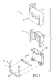
- FIG. 1 is a front exploded perspective view of an embodiment of an adjustment device for a seat belt mechanism in accordance with the present invention
- FIG. 2 is a front exploded perspective view of the adjustment device in FIG. 1 , showing the base, the guide, and the holding bar are assembled;
- FIG. 3 is a front exploded perspective view of another embodiment of an adjustment device for a seat belt mechanism in accordance with the present invention.
- FIG. 4 is a front exploded perspective view of the adjustment device in FIG. 1 , showing the base, the guide, the holding bar, and the connector are assembled;
- FIG. 5 is a back exploded perspective view of the adjustment device in FIG. 4 ;
- FIG. 6 is a back perspective view of the adjustment device in FIG. 1 , shown fully assembled;
- FIG. 7 is a schematic view of applying the adjustment device in FIG. 1 to the webbing of the seat belt mechanism fastened on a user;
- FIG. 8 is a schematic cross sectional side view of fixedly mounting the adjustment device of FIG. 1 on the webbing;
- FIG. 9 is a cross sectional side view of pushing the manipulating unit of the adjustment device in FIG. 1 upwardly and releasing the first segment of the webbing from the held state;
- FIG. 10 is a cross sectional side view of pulling the manipulating unit of the adjustment device in FIG. 1 downwardly and releasing the first segment of the webbing from the held state.
- an embodiment of an adjustment device 10 for a seat belt mechanism comprises a frame 20 , a guide 30 , a holding bar 40 , a connector 50 , and a manipulating unit 60 .
- the frame 20 comprises a base 21 , a holding inclined surface 22 formed on a front side of the base 21 , two straight edges 23 , two insertion slots 24 , two hooks 25 , two resilient blocks 26 , and two engaging protrusions 27 .
- the straight edges 23 are disposed at a left side of the base 21 and a right side of the base 21 respectively.
- the holding inclined surface 22 is disposed between the straight edges 23 .
- the holding inclined surface 22 is inclined forwardly from top to bottom.
- the insertion slots 24 are disposed at the left side of the base 21 and the right side of the base 21 respectively, and are adjacent to a bottom side of the base 21 .
- the hooks 25 are disposed at the left side of the base 21 and the right side of the base 21 respectively, and are adjacent to a top side of the base 21 .
- the resilient blocks 26 are disposed at a top of the left side of the base 21 and a top of the right side of the base 21 respectively.
- the engaging protrusions 27 protrude outwardly from a bottom of the left side of the base 21 and a bottom of the right side of the base 21 respectively.
- the engaging protrusions 27 are arranged respectively under the resilient blocks 26 .
- the guide 30 comprises two guiding bars 31 .
- the guiding bars 31 are fixed at a left side of the frame 20 and a right side of the frame 20 respectively.
- the guiding bars 31 are disposed in front of the straight edges 23 at an interval.
- Each of the guiding slots 32 is formed between a corresponding one of the guiding bars 31 and a corresponding one of the straight edges 23 .
- the guiding slots 32 extend longitudinally.
- the guiding bars 31 are two independent elements.
- the guide 30 further comprises a cross bar 33 connected between the guiding bars 31 .
- the guide 30 is integrated as one single part.
- each of the guiding bars 31 comprises a top end, a bottom end, an upper protrusion 311 extending backwardly from the top end, a lower protrusion 312 extending backwardly from the bottom end, and an engaging notch 313 disposed on the top end.
- the upper protrusion 311 abuts the top side of the base 21
- the lower protrusion 312 is inserted into a corresponding one of the insertion slots 24
- the engaging notch 313 is engaged with a corresponding one of the hooks 25 , so as to fix the guide 30 on the base 21 .
- the holding bar 40 is transversely disposed at the front side of the base 21 and on the holding inclined surface 22 .
- the holding bar 40 comprises two opposite ends extending into the guiding slots 32 respectively, so that the holding bar 40 may move up and down along the guiding slots 32 .
- the holding bar 40 comprises two annular recesses 41 formed on the two opposite ends respectively. Each of the annular recesses 41 is connected with a corresponding one of the guiding bars 31 and a corresponding one of the straight edges 23 .
- the connector 50 is mounted around the frame 20 .
- the connector 50 comprises two side walls 51 , a back wall 52 , a cross arm 53 , a through slot 54 , two guiding grooves 55 , two top engaging recesses 56 , and two bottom engaging recesses 57 .
- the side walls 51 are arranged at an interval.
- the back wall 52 is connected between rear portions of the side walls 51 .
- the cross arm 53 is connected between tops of the side walls 51 and is disposed above the holding bar 40 .
- the through slot 54 extends longitudinally and is surrounded by the back wall 52 and a back side of the frame 20 .
- the guiding grooves 55 are disposed on the rear portions of the side walls 51 respectively and extend longitudinally.
- the top engaging recesses 56 are disposed on the tops of the side walls 51 respectively. Each of the top engaging recesses 56 is connected to a corresponding one of the guiding grooves 55 .
- the bottom engaging recesses 57 are disposed on bottoms of the side walls 51 respectively.
- the connector 50 is fixed with the frame 20 by engaging the top engaging recesses 56 with the resilient blocks 26 respectively, and engaging the bottom engaging recesses 57 with the engaging protrusions 27 respectively.
- the manipulating unit 60 is slidably mounted around the connector 50 .
- the manipulating unit 60 comprises a front slat 61 , two side slats 62 , a pushing portion 63 , two limit portions 64 , and two sliding rails 65 .
- the front slat 61 is positioned in front of the frame 20 and the guide 30 .
- the side slats 62 extend backwardly from a left side of the front slat 61 and a right side of the front slat 61 respectively.
- the side slats 62 are adjacent to the side walls 51 respectively.
- the pushing portion 63 protrudes backwardly on a back side of the front slat 61 .
- the pushing portion 63 is disposed under the holding bar 40 and in front of the holding inclined surface 22 .
- the limit portions 64 are disposed on the top sides of the two side slats 62 respectively.
- the limit portions 64 are disposed above the connector 50 .
- the sliding rails 65 are longitudinally disposed on the side slats 62 respectively.
- the sliding rails 65 are disposed in the guiding grooves 55 respectively, so that the manipulating unit 60 may slide up and down relative to the connector 50 .
- the adjustment device 10 further comprises an elastomer 80 and a connecting piece 81 .
- the elastomer 80 is mounted through the through slot 54 and around the back wall 52 .
- the connecting piece 81 is mounted on the elastomer 80 .
- the adjustment device 10 is mounted on a seat belt mechanism.
- the seat belt mechanism comprises a webbing 70 , a retractor 71 , and a guiding ring 72 .
- the webbing 70 is pulled out from the retractor 71 and passes through the guiding ring 72 .
- the webbing 70 has a first segment 701 passing by the front side of the user from top to bottom obliquely, and a second segment 702 connected with the first segment 701 and positioned between the retractor 71 and the guiding ring 72 .
- the connecting piece 81 mounted on the elastomer 80 is connected between the second segment 702 and the elastomer 80 .
- the first segment 701 extends through the top of the manipulating unit 60 , extends between the front slat 61 and the cross arm 53 , extends between the holding bar 40 and the holding inclined surface 22 , extends between the pushing portion 63 and the holding inclined surface 22 , and extends outwardly from the bottom of the adjustment device 10 .
- the elastomer 80 and the connecting piece 81 may be omitted for mounting the adjustment device 10 .
- the second segment 702 may pass through the through slot 54 directly.
- FIG. 8 shows that the adjustment device 10 is fixedly mounted on the webbing 70 . Since the first segment 701 of the webbing 70 abuts against the cross arm 53 and is coiled around the holding bar 40 , the holding bar 40 is pushed toward the holding inclined surface 22 by the tension of the webbing 70 . As such, the first segment 701 is clamped between the holding bar 40 and the holding inclined surface 22 . Further, when the webbing 70 and the frame 20 are moved relative to each other, the relative position between the webbing 70 and the frame 20 may be automatically locked by the frictions between the webbing 70 and the holding bar 40 , between the webbing 70 and the holding inclined surface 22 , and between the holding bar 40 and the guide 30 .
- the manipulating unit 60 is moved upwardly relative to the frame 20 , and the pushing portion 63 forces the holding bar 40 to move upwardly along the guiding slot 32 and away from the holding inclined surface 22 , so as to unlock the first segment 701 from the adjustment device 10 .
- the webbing 70 may be released from the holding inclined surface 22 and the holding bar 40 , and the whole adjustment device 10 may move upwardly along the first segment 701 . Accordingly, an increase in the height of the adjustment device 10 on the webbing 70 may be freely adjusted.
- the manipulating unit 60 is moved downwardly relative to the frame 20 .
- the limit portion 64 presses the connector 50 to force the frame 20 to move downwardly relative to the webbing 70 .
- the holding bar 40 is moved away from the holding inclined surface 22 by the friction between the holding bar 40 and the first segment 701 .
- the first segment 701 is unlocked from the adjustment device 10 .
- the whole adjustment device 10 may move downwardly along the first segment 701 . Accordingly, a decrease in the height of the adjustment device 10 on the webbing 70 may be freely adjusted.
- the holding bar 40 may be pushed toward the holding inclined surface 22 by the tension of the webbing 70 , and the adjustment device may automatically lock the webbing 70 again.
Landscapes
- Engineering & Computer Science (AREA)
- Mechanical Engineering (AREA)
- Automotive Seat Belt Assembly (AREA)
Abstract
Description
- This application is based upon and claims priority under 35 U.S.C. 119 from Taiwan Patent Application No. 105203609 filed on Mar. 16, 2016, which is hereby specifically incorporated herein by this reference thereto.
- The present invention relates to an adjustment device, and more particularly to an adjustment device applied to a seat belt mechanism of a motor vehicle.
- A seat belt mechanism is designed for the safety of the driver or the passenger seated on the seat of the motor vehicle. Generally, the seat belt mechanism has a retractor, a webbing, a guiding ring, a tongue mounted on the webbing, and a buckle. The retractor is mounted inside the motor vehicle. The guiding ring is mounted in the motor vehicle at a position above the retractor. When a user is seated on the seat, the webbing is pulled out from the retractor, passes through the guiding ring, and passes by the front side of the user's torso from top to bottom obliquely. And then the tongue is connected with the buckle, so as to restrain the user on the seat.
- For the safety and the comfort of the user, the height of the guiding ring for small-sized cars is designed to be adjustable. In this way, the height of the guiding ring may be adjusted according to the height of the user, so as to prevent the webbing from abutting against the neck of the user and to improve the comfort. However, the adjustment range of the guiding ring is short and the height adjustment is done in multiple steps. As such, the guiding ring barely meets the needs of different users in terms of comfort.
- In addition, the height of the guiding ring for large-sized cars, such as a truck or a sport utility vehicle (SUV), may not be adjusted. The webbing may be at an improper position when in use. Therefore, the driver or the passenger seated in the large-sized cars is unsafe and uncomfortable when using the seat belt.
- To overcome the shortcomings, an adjustment device for a seat belt mechanism to mitigate or obviate the aforementioned problems is provided.
- An objective of the present invention is to provide an adjustment device for a seat belt mechanism to overcome the technical limitation in the insufficient comfort provided by the guiding ring for the users using the seat belt mechanism.
- In accordance with an embodiment, the adjustment device comprises a frame, a guide, a holding bar, a connector, and a manipulating unit. The frame comprises a base, two straight edges, and a holding inclined surface. The straight edges are respectively disposed at a left side of the base and a right side of the base. The holding inclined surface is formed on a front side of the base, disposed between the straight edges, and inclined forwardly from top to bottom. The guide comprises two guiding bars and two guiding slots. The guiding bars are respectively fixed at a left side of the frame and a right side of the frame, and are disposed in front of the straight edges at an interval. Each of the guiding slots is surrounded by a corresponding one of the guiding bars and a corresponding one of the straight edges, and extends longitudinally. The holding bar is transversely disposed on the holding inclined surface. The holding bar comprises two opposite ends respectively extending into the guiding slots, so as to be movable along the guiding slots. The connector is mounted around the frame. The connector comprises two side walls arranged at an interval, a back wall connected between the side walls, a cross arm connected between the side walls and disposed above the holding bar, and a through slot extending longitudinally. The through slot is surrounded by the back wall and a back side of the frame. The manipulating unit is slidably mounted around the connector. The manipulating unit comprises a front slat, two side slats, a pushing portion, and two limits. The front slat is positioned in front of the frame and the guide. The side slats respectively extend backwardly from a left side of the front slat and a right side of the front slat. The side slats are adjacent to the side walls respectively. The pushing portion is formed on a back side of the front slat. The pushing portion is disposed under the holding bar and in front of the holding inclined surface. The limit portions are disposed on the top sides of the side slats respectively and above a top of the connector.
- The adjustment device may be mounted through by a first segment of a webbing of a seat belt mechanism and mounted on a second segment of the same webbing, wherein the first segment passes by the front side of the user's torso from top to bottom obliquely, and the second segment is positioned between a retractor and a guiding ring of the seat belt mechanism vertically. The holding bar and the holding inclined surface may clamp the first segment to lock the adjustment device on the webbing. The adjustment device may be unlocked by the manipulating unit to move upwardly or downwardly along the webbing for a stepless height adjustment. After the external force exerted on the manipulating unit is removed, the holding bar may be pushed toward the holding inclined surface by the tension of the webbing, and thus the adjustment device automatically locks on the webbing. As such, the position of the webbing may be adjusted easily, thereby enhancing the safety and the comfort of a user using the seat belt mechanism.
- Further, the height of the adjustment device on the webbing is adjusted as follows.
- In one aspect, the user only needs to apply a downward pressure relative to the webbing on the connector by the manipulating unit to force the frame to move downwardly relative to the webbing, and thus the holding bar is moved away from the holding inclined surface by the friction between the holding bar and the first segment to disable the adjustment device's locking facility to the first segment. And then the height of the adjustment device on the webbing may be decreased.
- In another aspect, the user only needs to move the manipulating unit upwardly relative to the webbing by hand, and thus the holding bar is pushed upwardly by the manipulating unit and is moved away from the holding inclined surface to disable the adjustment device's locking facility to the first segment. Then the height of the adjustment device on the webbing may be increased.
- Once the height of the adjustment device on the webbing is adjusted to the desired position, the holding bar may be pushed toward the holding inclined surface by the tension of the webbing, and the adjustment device may be automatically locked on the webbing again. Accordingly, the operation of the adjustment device is simple.
- Therefore, the adjustment device not only has the advantage of enhancing the comfort and the safety of using the seat belt mechanism, but also has the advantage of simple operation.
- Other objectives, advantages, and novel features of the embodiments of the present invention will become more apparent from the following detailed description when taken in conjunction with the accompanying drawings.
-
FIG. 1 is a front exploded perspective view of an embodiment of an adjustment device for a seat belt mechanism in accordance with the present invention; -
FIG. 2 is a front exploded perspective view of the adjustment device inFIG. 1 , showing the base, the guide, and the holding bar are assembled; -
FIG. 3 is a front exploded perspective view of another embodiment of an adjustment device for a seat belt mechanism in accordance with the present invention; -
FIG. 4 is a front exploded perspective view of the adjustment device inFIG. 1 , showing the base, the guide, the holding bar, and the connector are assembled; -
FIG. 5 is a back exploded perspective view of the adjustment device inFIG. 4 ; -
FIG. 6 is a back perspective view of the adjustment device inFIG. 1 , shown fully assembled; -
FIG. 7 is a schematic view of applying the adjustment device inFIG. 1 to the webbing of the seat belt mechanism fastened on a user; -
FIG. 8 is a schematic cross sectional side view of fixedly mounting the adjustment device ofFIG. 1 on the webbing; -
FIG. 9 is a cross sectional side view of pushing the manipulating unit of the adjustment device inFIG. 1 upwardly and releasing the first segment of the webbing from the held state; and -
FIG. 10 is a cross sectional side view of pulling the manipulating unit of the adjustment device inFIG. 1 downwardly and releasing the first segment of the webbing from the held state. - With reference to
FIG. 1 , an embodiment of anadjustment device 10 for a seat belt mechanism comprises aframe 20, aguide 30, a holdingbar 40, aconnector 50, and a manipulatingunit 60. - With reference to
FIGS. 1 and 2 , theframe 20 comprises abase 21, a holdinginclined surface 22 formed on a front side of thebase 21, twostraight edges 23, twoinsertion slots 24, twohooks 25, tworesilient blocks 26, and two engagingprotrusions 27. Thestraight edges 23 are disposed at a left side of thebase 21 and a right side of the base 21 respectively. The holdinginclined surface 22 is disposed between thestraight edges 23. The holdinginclined surface 22 is inclined forwardly from top to bottom. Theinsertion slots 24 are disposed at the left side of thebase 21 and the right side of the base 21 respectively, and are adjacent to a bottom side of thebase 21. Thehooks 25 are disposed at the left side of thebase 21 and the right side of the base 21 respectively, and are adjacent to a top side of thebase 21. Theresilient blocks 26 are disposed at a top of the left side of thebase 21 and a top of the right side of the base 21 respectively. The engagingprotrusions 27 protrude outwardly from a bottom of the left side of thebase 21 and a bottom of the right side of the base 21 respectively. The engagingprotrusions 27 are arranged respectively under the resilient blocks 26. - With reference to
FIGS. 1 and 2 , theguide 30 comprises two guiding bars 31. The guiding bars 31 are fixed at a left side of theframe 20 and a right side of theframe 20 respectively. The guiding bars 31 are disposed in front of thestraight edges 23 at an interval. Each of the guidingslots 32 is formed between a corresponding one of the guiding bars 31 and a corresponding one of thestraight edges 23. The guidingslots 32 extend longitudinally. In an embodiment, as shown inFIG. 1 , the guiding bars 31 are two independent elements. In another embodiment, as shown inFIG. 3 , theguide 30 further comprises across bar 33 connected between the guiding bars 31. Theguide 30 is integrated as one single part. - With reference to
FIGS. 1 and 2 , each of the guiding bars 31 comprises a top end, a bottom end, anupper protrusion 311 extending backwardly from the top end, alower protrusion 312 extending backwardly from the bottom end, and anengaging notch 313 disposed on the top end. Theupper protrusion 311 abuts the top side of thebase 21, thelower protrusion 312 is inserted into a corresponding one of theinsertion slots 24, and the engagingnotch 313 is engaged with a corresponding one of thehooks 25, so as to fix theguide 30 on thebase 21. - With reference to
FIGS. 1 and 2 , the holdingbar 40 is transversely disposed at the front side of thebase 21 and on the holdinginclined surface 22. The holdingbar 40 comprises two opposite ends extending into the guidingslots 32 respectively, so that the holdingbar 40 may move up and down along the guidingslots 32. In an embodiment, as shown inFIGS. 1 and 3 , the holdingbar 40 comprises twoannular recesses 41 formed on the two opposite ends respectively. Each of theannular recesses 41 is connected with a corresponding one of the guiding bars 31 and a corresponding one of thestraight edges 23. - With reference to
FIGS. 1, 2, 4, and 5 , theconnector 50 is mounted around theframe 20. Theconnector 50 comprises twoside walls 51, aback wall 52, across arm 53, a throughslot 54, two guidinggrooves 55, two top engagingrecesses 56, and two bottom engaging recesses 57. Theside walls 51 are arranged at an interval. Theback wall 52 is connected between rear portions of theside walls 51. Thecross arm 53 is connected between tops of theside walls 51 and is disposed above the holdingbar 40. The throughslot 54 extends longitudinally and is surrounded by theback wall 52 and a back side of theframe 20. The guidinggrooves 55 are disposed on the rear portions of theside walls 51 respectively and extend longitudinally. The topengaging recesses 56 are disposed on the tops of theside walls 51 respectively. Each of the top engagingrecesses 56 is connected to a corresponding one of the guidinggrooves 55. Thebottom engaging recesses 57 are disposed on bottoms of theside walls 51 respectively. Theconnector 50 is fixed with theframe 20 by engaging the top engagingrecesses 56 with theresilient blocks 26 respectively, and engaging thebottom engaging recesses 57 with the engagingprotrusions 27 respectively. - With reference to
FIGS. 1, 4, and 5 , the manipulatingunit 60 is slidably mounted around theconnector 50. The manipulatingunit 60 comprises afront slat 61, twoside slats 62, a pushingportion 63, twolimit portions 64, and two slidingrails 65. Thefront slat 61 is positioned in front of theframe 20 and theguide 30. The side slats 62 extend backwardly from a left side of thefront slat 61 and a right side of thefront slat 61 respectively. The side slats 62 are adjacent to theside walls 51 respectively. The pushingportion 63 protrudes backwardly on a back side of thefront slat 61. The pushingportion 63 is disposed under the holdingbar 40 and in front of the holdinginclined surface 22. Thelimit portions 64 are disposed on the top sides of the twoside slats 62 respectively. Thelimit portions 64 are disposed above theconnector 50. The sliding rails 65 are longitudinally disposed on theside slats 62 respectively. The sliding rails 65 are disposed in the guidinggrooves 55 respectively, so that the manipulatingunit 60 may slide up and down relative to theconnector 50. - With reference to
FIGS. 1, 5 to 7 , theadjustment device 10 further comprises anelastomer 80 and a connectingpiece 81. Theelastomer 80 is mounted through the throughslot 54 and around theback wall 52. The connectingpiece 81 is mounted on theelastomer 80. - With reference to
FIGS. 1, and 6 to 8 , in use, theadjustment device 10 is mounted on a seat belt mechanism. The seat belt mechanism comprises awebbing 70, aretractor 71, and a guidingring 72. Thewebbing 70 is pulled out from theretractor 71 and passes through the guidingring 72. Thewebbing 70 has afirst segment 701 passing by the front side of the user from top to bottom obliquely, and asecond segment 702 connected with thefirst segment 701 and positioned between theretractor 71 and the guidingring 72. The connectingpiece 81 mounted on theelastomer 80 is connected between thesecond segment 702 and theelastomer 80. Thefirst segment 701 extends through the top of the manipulatingunit 60, extends between thefront slat 61 and thecross arm 53, extends between the holdingbar 40 and the holdinginclined surface 22, extends between the pushingportion 63 and the holdinginclined surface 22, and extends outwardly from the bottom of theadjustment device 10. - Alternatively, the
elastomer 80 and the connectingpiece 81 may be omitted for mounting theadjustment device 10. In this way, thesecond segment 702 may pass through the throughslot 54 directly. -
FIG. 8 shows that theadjustment device 10 is fixedly mounted on thewebbing 70. Since thefirst segment 701 of thewebbing 70 abuts against thecross arm 53 and is coiled around the holdingbar 40, the holdingbar 40 is pushed toward the holdinginclined surface 22 by the tension of thewebbing 70. As such, thefirst segment 701 is clamped between the holdingbar 40 and the holdinginclined surface 22. Further, when thewebbing 70 and theframe 20 are moved relative to each other, the relative position between thewebbing 70 and theframe 20 may be automatically locked by the frictions between thewebbing 70 and the holdingbar 40, between thewebbing 70 and the holdinginclined surface 22, and between the holdingbar 40 and theguide 30. - With reference to
FIG. 9 , the manipulatingunit 60 is moved upwardly relative to theframe 20, and the pushingportion 63 forces the holdingbar 40 to move upwardly along the guidingslot 32 and away from the holdinginclined surface 22, so as to unlock thefirst segment 701 from theadjustment device 10. In this way, thewebbing 70 may be released from the holdinginclined surface 22 and the holdingbar 40, and thewhole adjustment device 10 may move upwardly along thefirst segment 701. Accordingly, an increase in the height of theadjustment device 10 on thewebbing 70 may be freely adjusted. - With reference to
FIG. 10 , the manipulatingunit 60 is moved downwardly relative to theframe 20. Thelimit portion 64 presses theconnector 50 to force theframe 20 to move downwardly relative to thewebbing 70. The holdingbar 40 is moved away from the holdinginclined surface 22 by the friction between the holdingbar 40 and thefirst segment 701. As such, thefirst segment 701 is unlocked from theadjustment device 10. In this way, thewhole adjustment device 10 may move downwardly along thefirst segment 701. Accordingly, a decrease in the height of theadjustment device 10 on thewebbing 70 may be freely adjusted. - Once the height of the
adjustment device 10 on thewebbing 70 is adjusted to the desired position, the holdingbar 40 may be pushed toward the holdinginclined surface 22 by the tension of thewebbing 70, and the adjustment device may automatically lock thewebbing 70 again.
Claims (19)
Applications Claiming Priority (3)
| Application Number | Priority Date | Filing Date | Title |
|---|---|---|---|
| TW105203609 | 2016-03-16 | ||
| TW105203609U TWM523328U (en) | 2016-03-16 | 2016-03-16 | Woven band adjustment device of safety belt |
| TW105203609U | 2016-03-16 |
Publications (2)
| Publication Number | Publication Date |
|---|---|
| US20170267209A1 true US20170267209A1 (en) | 2017-09-21 |
| US10011245B2 US10011245B2 (en) | 2018-07-03 |
Family
ID=56756759
Family Applications (1)
| Application Number | Title | Priority Date | Filing Date |
|---|---|---|---|
| US15/451,576 Active 2037-03-15 US10011245B2 (en) | 2016-03-16 | 2017-03-07 | Adjustment device for seat belt mechanism |
Country Status (2)
| Country | Link |
|---|---|
| US (1) | US10011245B2 (en) |
| TW (1) | TWM523328U (en) |
Cited By (6)
| Publication number | Priority date | Publication date | Assignee | Title |
|---|---|---|---|---|
| EP3486126A1 (en) * | 2017-11-20 | 2019-05-22 | Liang-Hsiung Wang | Webbing adjustment device |
| US10994694B2 (en) * | 2018-07-12 | 2021-05-04 | Liang Hsiung Wang | Webbing height adjustment device |
| CN113276798A (en) * | 2021-06-21 | 2021-08-20 | 东风汽车集团股份有限公司 | Back row safety belt structure |
| US20220055571A1 (en) * | 2020-08-21 | 2022-02-24 | Illinois Tool Works Inc. | Belt guide |
| JP2025042585A (en) * | 2023-09-14 | 2025-03-27 | 宏霖工業股▲フン▼有限公司 | Webbing height adjustment device |
| JP2025078570A (en) * | 2023-11-08 | 2025-05-20 | 宏霖工業股▲フン▼有限公司 | Webbing height adjuster and webbing height adjustment device |
Families Citing this family (1)
| Publication number | Priority date | Publication date | Assignee | Title |
|---|---|---|---|---|
| US10710548B2 (en) * | 2018-04-17 | 2020-07-14 | Ford Global Technologies, Llc | Seatbelt guide assembly |
Family Cites Families (10)
| Publication number | Priority date | Publication date | Assignee | Title |
|---|---|---|---|---|
| JPS5235625Y2 (en) * | 1972-05-13 | 1977-08-13 | ||
| US4799737A (en) * | 1987-03-16 | 1989-01-24 | Greene Marc B | Shoulder belt adjuster |
| US4796919A (en) * | 1988-01-12 | 1989-01-10 | Linden Scott R | Vehicle seatbelt deflection device |
| US4893835A (en) * | 1988-01-12 | 1990-01-16 | Linden Scott R | Vehicle seatbelt deflection device |
| WO2003009717A2 (en) * | 2001-07-26 | 2003-02-06 | Indiana Mills & Manufacturing, Inc. | Web adjuster device |
| US7506413B2 (en) * | 2004-10-08 | 2009-03-24 | Indiana Mills & Manufacturing, Inc. | Web position adjusting device |
| EP1918163B1 (en) * | 2006-10-30 | 2009-12-16 | Key Safety Systems, Inc. | Child safety restraint |
| DE602006007157D1 (en) * | 2006-11-29 | 2009-07-16 | Key Safety Systems Inc | Safety restraint system for a child |
| EP2045147B1 (en) * | 2007-10-03 | 2012-05-02 | Key Safety Systems, Inc. | Seat belt system for adults and children |
| KR101766480B1 (en) * | 2013-04-17 | 2017-08-08 | 잉위 쑨 | Locking Device, Vehicle Seat Belt Adjusting Device, and Vehicle Seat Belt |
-
2016
- 2016-03-16 TW TW105203609U patent/TWM523328U/en not_active IP Right Cessation
-
2017
- 2017-03-07 US US15/451,576 patent/US10011245B2/en active Active
Cited By (11)
| Publication number | Priority date | Publication date | Assignee | Title |
|---|---|---|---|---|
| EP3486126A1 (en) * | 2017-11-20 | 2019-05-22 | Liang-Hsiung Wang | Webbing adjustment device |
| JP2019094049A (en) * | 2017-11-20 | 2019-06-20 | 亮雄 王 | Belt adjustment device |
| US10654442B2 (en) * | 2017-11-20 | 2020-05-19 | Liang-Hsiung Wang | Webbing adjustment device |
| US10994694B2 (en) * | 2018-07-12 | 2021-05-04 | Liang Hsiung Wang | Webbing height adjustment device |
| US20220055571A1 (en) * | 2020-08-21 | 2022-02-24 | Illinois Tool Works Inc. | Belt guide |
| US11628799B2 (en) * | 2020-08-21 | 2023-04-18 | Illinois Tool Works Inc. | Belt guide |
| CN113276798A (en) * | 2021-06-21 | 2021-08-20 | 东风汽车集团股份有限公司 | Back row safety belt structure |
| JP2025042585A (en) * | 2023-09-14 | 2025-03-27 | 宏霖工業股▲フン▼有限公司 | Webbing height adjustment device |
| JP7784164B2 (en) | 2023-09-14 | 2025-12-11 | 宏霖工業股▲フン▼有限公司 | Webbing height adjustment device |
| JP2025078570A (en) * | 2023-11-08 | 2025-05-20 | 宏霖工業股▲フン▼有限公司 | Webbing height adjuster and webbing height adjustment device |
| JP7797042B2 (en) | 2023-11-08 | 2026-01-13 | 宏霖工業股▲フン▼有限公司 | Webbing height adjuster and webbing height adjusting device |
Also Published As
| Publication number | Publication date |
|---|---|
| US10011245B2 (en) | 2018-07-03 |
| TWM523328U (en) | 2016-06-11 |
Similar Documents
| Publication | Publication Date | Title |
|---|---|---|
| US10011245B2 (en) | Adjustment device for seat belt mechanism | |
| US10981536B2 (en) | Multi-point seat belt assembly | |
| US10654442B2 (en) | Webbing adjustment device | |
| US8833854B2 (en) | Child seat | |
| US10173635B2 (en) | Webbing adjustment device for a seat belt system | |
| US8991919B2 (en) | Child safety seat for vehicles | |
| US20120181829A1 (en) | Child Safety Seat | |
| WO2015025801A1 (en) | Locking tongue | |
| CN106183920B (en) | The headrest of automotive seat and seat including the headrest | |
| GB2611706A (en) | Child restraint system and adjustable headrest assembly thereof | |
| US11007973B2 (en) | Webbing-buckling device of a multi-point seat belt system | |
| JP2020011718A (en) | Webbing height adjustment device | |
| WO2022076437A1 (en) | Child restraint system with belt tensioning mechanism | |
| KR101560986B1 (en) | Seat for vehicle | |
| US7144086B1 (en) | Shoulder belt clip for child safety seats and child carriers | |
| JP7784164B2 (en) | Webbing height adjustment device | |
| EP3715187A1 (en) | Multi-point seat belt system | |
| TWM530555U (en) | Belt adjuster of seat belt | |
| TWM526302U (en) | Ribbon adjustment device of safety belt | |
| KR20200058188A (en) | Webbing guide of rear seat for car | |
| KR100610963B1 (en) | Positioning device of seat belt webbing | |
| KR20110061735A (en) | Stepless adjustable headrest guide for car seat | |
| KR200325931Y1 (en) | Apparatus to fix belt of safety chair for young child in automobile | |
| JPH01127434A (en) | Seat belt anchor device | |
| JP2006103532A (en) | Webbing insertion member |
Legal Events
| Date | Code | Title | Description |
|---|---|---|---|
| AS | Assignment |
Owner name: WANG, LIANG-HSIUNG, TAIWAN Free format text: ASSIGNMENT OF ASSIGNORS INTEREST;ASSIGNORS:WANG, LIANG-HSIUNG;CHU, CHIA-CHUN;REEL/FRAME:041481/0952 Effective date: 20170307 |
|
| STCF | Information on status: patent grant |
Free format text: PATENTED CASE |
|
| MAFP | Maintenance fee payment |
Free format text: PAYMENT OF MAINTENANCE FEE, 4TH YR, SMALL ENTITY (ORIGINAL EVENT CODE: M2551); ENTITY STATUS OF PATENT OWNER: SMALL ENTITY Year of fee payment: 4 |
|
| FEPP | Fee payment procedure |
Free format text: MAINTENANCE FEE REMINDER MAILED (ORIGINAL EVENT CODE: REM.); ENTITY STATUS OF PATENT OWNER: SMALL ENTITY |