US10173635B2 - Webbing adjustment device for a seat belt system - Google Patents
Webbing adjustment device for a seat belt system Download PDFInfo
- Publication number
- US10173635B2 US10173635B2 US15/415,591 US201715415591A US10173635B2 US 10173635 B2 US10173635 B2 US 10173635B2 US 201715415591 A US201715415591 A US 201715415591A US 10173635 B2 US10173635 B2 US 10173635B2
- Authority
- US
- United States
- Prior art keywords
- webbing
- frame
- adjustment device
- slider
- hole
- Prior art date
- Legal status (The legal status is an assumption and is not a legal conclusion. Google has not performed a legal analysis and makes no representation as to the accuracy of the status listed.)
- Active, expires
Links
Images


Classifications
-
- B—PERFORMING OPERATIONS; TRANSPORTING
- B60—VEHICLES IN GENERAL
- B60R—VEHICLES, VEHICLE FITTINGS, OR VEHICLE PARTS, NOT OTHERWISE PROVIDED FOR
- B60R22/00—Safety belts or body harnesses in vehicles
- B60R22/18—Anchoring devices
- B60R22/20—Anchoring devices adjustable in position, e.g. in height
-
- A—HUMAN NECESSITIES
- A44—HABERDASHERY; JEWELLERY
- A44B—BUTTONS, PINS, BUCKLES, SLIDE FASTENERS, OR THE LIKE
- A44B11/00—Buckles; Similar fasteners for interconnecting straps or the like, e.g. for safety belts
- A44B11/02—Buckles; Similar fasteners for interconnecting straps or the like, e.g. for safety belts frictionally engaging surface of straps
- A44B11/06—Buckles; Similar fasteners for interconnecting straps or the like, e.g. for safety belts frictionally engaging surface of straps with clamping devices
- A44B11/10—Buckles; Similar fasteners for interconnecting straps or the like, e.g. for safety belts frictionally engaging surface of straps with clamping devices sliding wedge
-
- B—PERFORMING OPERATIONS; TRANSPORTING
- B60—VEHICLES IN GENERAL
- B60R—VEHICLES, VEHICLE FITTINGS, OR VEHICLE PARTS, NOT OTHERWISE PROVIDED FOR
- B60R22/00—Safety belts or body harnesses in vehicles
- B60R22/18—Anchoring devices
- B60R2022/1818—Belt guides
-
- B—PERFORMING OPERATIONS; TRANSPORTING
- B60—VEHICLES IN GENERAL
- B60Y—INDEXING SCHEME RELATING TO ASPECTS CROSS-CUTTING VEHICLE TECHNOLOGY
- B60Y2304/00—Optimising design; Manufacturing; Testing
- B60Y2304/05—Reducing production costs, e.g. by redesign
-
- Y—GENERAL TAGGING OF NEW TECHNOLOGICAL DEVELOPMENTS; GENERAL TAGGING OF CROSS-SECTIONAL TECHNOLOGIES SPANNING OVER SEVERAL SECTIONS OF THE IPC; TECHNICAL SUBJECTS COVERED BY FORMER USPC CROSS-REFERENCE ART COLLECTIONS [XRACs] AND DIGESTS
- Y10—TECHNICAL SUBJECTS COVERED BY FORMER USPC
- Y10T—TECHNICAL SUBJECTS COVERED BY FORMER US CLASSIFICATION
- Y10T24/00—Buckles, buttons, clasps, etc.
- Y10T24/40—Buckles
- Y10T24/4002—Harness
- Y10T24/4012—Clamping
- Y10T24/4019—Sliding part or wedge
-
- Y—GENERAL TAGGING OF NEW TECHNOLOGICAL DEVELOPMENTS; GENERAL TAGGING OF CROSS-SECTIONAL TECHNOLOGIES SPANNING OVER SEVERAL SECTIONS OF THE IPC; TECHNICAL SUBJECTS COVERED BY FORMER USPC CROSS-REFERENCE ART COLLECTIONS [XRACs] AND DIGESTS
- Y10—TECHNICAL SUBJECTS COVERED BY FORMER USPC
- Y10T—TECHNICAL SUBJECTS COVERED BY FORMER US CLASSIFICATION
- Y10T24/00—Buckles, buttons, clasps, etc.
- Y10T24/40—Buckles
- Y10T24/4079—Sliding part of wedge
- Y10T24/4084—Looped strap
Definitions
- the present invention relates to a webbing adjustment device, and more particularly to a webbing adjustment device to adjust a height of an upper area of a three-point seat belt system.
- a seat belt system is applied on a motor vehicle for protecting every occupant in the vehicle.
- a retractor of the seat belt system is mounted on a support pillar in the vehicle.
- a webbing of the seat belt system is pulled out from the retractor of the seat belt system.
- the webbing of the seat belt system is passed through a guiding ring of the seat belt system, and then the webbing is obliquely passed the front of the occupant's torso.
- a tongue mounted around the webbing is inserted into a buckle mounted on a seat of the vehicle.
- a triangular protection area can be formed by the webbing among the guiding ring, the buckle receiving tongue, and the retractor the vehicle in use.
- the seat belt system is a three-point seat belt system. The body of the occupant in the vehicle is restrained on the seat in the vehicle by the webbing.
- a conventional height adjustment device for the webbing of the seat belt system is adapted to a specific vehicle and has some defects, such as complex structure, short range of adjustment, multi-step adjustment, and complicated operation. Thus, it is necessary to invent a simplified, convenient, and useful height adjustment device to adjust the height of the webbing near the shoulder of the occupant in the vehicle.
- the present invention provides a webbing adjustment device for a seat belt system to mitigate or obviate the aforementioned problems.
- the objective of the invention is to provide a webbing adjustment device that can be adjusted steplessly, reduces the production cost and the assembly cost of the webbing adjustment device, locks automatically, and is easy to operate.
- the webbing adjustment device has a frame and a slider.
- the frame has a first hole and a second hole.
- the first hole is formed through the frame.
- the second hole is formed through the frame below the first hole of the frame.
- a front section of a seat belt webbing extends through the second hole of the frame.
- the slider is detachably connected to the frame.
- the slider has a first end portion, a second end portion, a connecting portion, and a through groove.
- the first end portion is formed on the slider.
- the second end portion is formed on the slider and is opposite to the first end portion of the slider.
- the connecting portion is formed on the slider between the first end portion and the second end portion of the slider, and the connecting portion has a top surface and a bottom surface.
- the through groove is formed through the connecting portion from the top surface of the connecting portion to the bottom surface of the connecting portion.
- the connecting portion of the slider is inserted through the first hole of the frame, and a rear section of the webbing is passed through the first hole of the frame and the through groove of the slider, and the rear section of the webbing is locked or unlocked by a relative motion between the frame and the slider.
- the webbing adjustment device is mounted on a webbing of a seat belt system.
- the webbing adjustment device is below a guiding ring of the seat belt system.
- the webbing adjustment device is located between a front section of the webbing and a rear section of the webbing.
- the rear section of the webbing is passed through the webbing adjustment device.
- the webbing adjustment device is connected to the front section of the webbing.
- a positioning point of the webbing near the guiding ring is restricted by the webbing adjustment device for protecting the user's neck from slashing by the webbing.
- a height of the positioning point of the webbing is adjusted by the webbing adjustment device.
- the relative motion between the frame and the slider is generated to unlock the webbing.
- the webbing adjustment device may be moved upward or downward to a suitable position. When the occupant stop moving the webbing adjustment device, the webbing adjustment device locks the webbing automatically by the tension of the webbing, ensuring that the positioning point of the webbing is close to the height of the shoulder of the user
- the webbing adjustment device is adapted to various types of vehicles.
- the webbing adjustment device is simplified in structure, easy in operation, and cost-effective in manufacture and assembly.
- the webbing adjustment device can be adjusted steplessly.
- the adjustment range of the webbing adjustment device is long.
- the webbing adjustment device is easy to operate and automatically locks the webbing.
- the webbing adjustment device further has a cover.
- the cover is moveably mounted on the frame. Two side edges of the frame are inserted into two slide grooves of the cover respectively. A stop portion of the cover is mounted above the first end portion of the slider. The user adjusts the cover to adjust the height of the positioning point of the webbing adjustment device.
- FIG. 1 is a perspective view of a first embodiment of a webbing adjustment device for a seat belt system in accordance with the present invention
- FIG. 2 is another perspective view of the webbing adjustment device in FIG. 1 ;
- FIG. 3 is an exploded perspective view of the webbing adjustment device in FIG. 1 ;
- FIG. 4 is another exploded perspective view of the webbing adjustment device in FIG. 1 ;
- FIG. 5 is an operational front side view of the webbing adjustment device in FIGS. 1 and 2 , showing the webbing adjustment device is assembled on the seat belt system;
- FIG. 6 is an enlarged and operational front side view in partial section of the webbing adjustment device in FIG. 5 ;
- FIG. 7 is an enlarged and operational front side view in partial section of the webbing adjustment device in FIGS. 1 and 2 , showing a frame of the webbing adjustment device is connected to a connecting strap and a connecting element;
- FIG. 8 is an operational front side view in partial section of the webbing adjustment device in FIGS. 1 and 2 , showing the frame moves upwardly relative to a slider of the webbing adjustment device;
- FIG. 9 is an operational front side view in partial section of the webbing adjustment device in FIGS. 1 and 2 , showing the slider moves downwardly relative to the frame of the webbing adjustment device;
- FIG. 10 is a perspective view of a second embodiment of a webbing adjustment device for a seat belt system in accordance with the present invention.
- FIG. 11 is another perspective view of the second embodiment of the webbing adjustment device in FIG. 10 ;
- FIG. 12 is an exploded perspective view of the second embodiment of the webbing adjustment device in FIGS. 10 and 11 ;
- FIG. 13 is another exploded perspective view of the second embodiment of the webbing adjustment device in FIGS. 10 and 11 ;
- FIG. 14 is an operational front side view of the second embodiment of the webbing adjustment device in FIGS. 10 and 11 , showing the webbing adjustment device is mounted on the seat belt system;
- FIG. 15 is an enlarged and operational front side view in partial section of the second embodiment of the webbing adjustment device in FIG. 14 ;
- FIG. 16 is an enlarged and operational front side view in partial section of the second embodiment of the webbing adjustment device in FIGS. 10 and 11 , showing the frame of the webbing adjustment device is connected to the connecting strap and the connecting element;
- FIG. 17 is an operational front side view in partial section of the second embodiment of the webbing adjustment device in FIGS. 10 and 11 , showing a cover of the webbing adjustment device moves upwardly;
- FIG. 18 is an operational front side view in partial section of the second embodiment of the webbing adjustment device in FIGS. 10 and 11 , showing the cover of the webbing adjustment device moves downwardly;
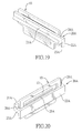
- FIG. 19 is a perspective view of a third embodiment of a webbing adjustment device for a seat belt system in accordance with the present invention.
- FIG. 20 is another perspective view of the third embodiment of the webbing adjustment device in FIG. 19 ;
- FIG. 21 is an exploded perspective view of the third embodiment of the webbing adjustment device in FIGS. 19 and 20 ;
- FIG. 22 is a bottom perspective view of the slider of the third embodiment of the webbing adjustment device in FIGS. 19 and 20 ;
- FIG. 23 is an enlarged and operational front side view in partial section of the third embodiment of the webbing adjustment device in FIGS. 19 and 20 , showing the webbing adjustment device is assembled on the seat belt system;
- FIG. 24 is an enlarged and operational front side view in partial section of the third embodiment of the webbing adjustment device in FIGS. 19 and 20 , showing the frame of the webbing adjustment device is connected to the connecting strap and the connecting element.
- a first embodiment of a webbing adjustment device 1 for a seat belt system in accordance with the present invention comprises a frame 10 and a slider 20 .
- the frame 10 has a first hole 11 and a second hole 12 .
- the first hole 11 is formed through the frame 10 .
- the second hole 12 is formed through the frame 10 below the first hole 11 of the frame 10 .
- a front section 41 of a webbing 40 extends through the second hole 12 of the frame 10 .
- the slider 20 is detachably connected to the frame 10 and has a first end portion 21 , a second end portion 22 , a connecting portion 23 , and a through groove 24 .
- the first end portion 21 is formed on the slider 20 .
- the second end portion 22 is formed on the slider 20 and is opposite to the first end portion 21 of the slider 20 .
- the connecting portion 23 is formed on the slider 20 between the first end portion 21 and the second end portion 22 of the slider 20 .
- the connecting portion 23 has a top surface and a bottom surface.
- the through groove 24 is formed through the connecting portion 23 from the top surface of the connecting portion 23 to the bottom surface of the connecting portion 23 . With reference to FIGS. 5 and 6 , the connecting portion 23 of the slider 20 is inserted through the first hole 11 of the frame 10 .
- a rear section 42 of the webbing 40 is passed through the first hole 11 of the frame 10 and the through groove 24 of the slider 20 , and the rear section 42 of the webbing 40 is locked or unlocked by a relative motion between the frame 10 and the slider 20 .
- the first hole 11 and the second hole 12 of the frame 10 are closed-type holes or open-type holes.
- the through groove 24 of the slider 20 is a closed-type groove or an open-type groove.
- the webbing 40 is inserted into the first hole 11 via the first slit and is inserted into the second hole 12 via the second slit.
- a third slit (not shown) is formed through an outer surface of the slider 20 and is in communication with the through groove 24 .
- the webbing 40 is inserted into the through groove 24 via the third slit. Therefore, the webbing adjustment device 1 can be easily assembled with the webbing 40 by a user.
- the connecting portion 23 is formed between the bottom of the first end portion 21 and the top of the second end portion 22 .
- the through groove 24 of the slider 20 is sloped from the top of the second end portion 22 toward the bottom of the first end portion 21 .
- a flange 25 is formed on the top of the second end portion 22 adjacent to the through groove 24 .
- the webbing adjustment device 1 is mounted on the webbing of the seat belt system.
- the webbing adjustment device 1 is connected between the front section 41 of the webbing 40 and the rear section 42 of the webbing 40 below a guiding ring 51 of the seat belt system.
- a section of the webbing 40 between a retractor 50 of the seat belt system and the guiding ring 51 is defined as the front section 41 .
- Another section of the webbing 40 between a tongue 52 of the seat belt system and the guiding ring 51 is defined as the rear section 42 .
- the front section 41 is directly passed through the second hole 12 of the frame 10 .
- the second hole 12 is a closed-type hole
- the front section 41 is directly inserted through the second hole 12 of the frame 10 .
- the front section 41 is inserted through the second hole 12 of the frame 10 via the second slit.
- the frame 10 of the webbing adjustment device 1 further has a connecting strap 13 and a connecting element 14 .
- the connecting strap 13 is connected to the frame 10 by extending through the second hole 12 of the frame 10 .
- the connecting element 14 is connected to the connecting strap 13 and is connected to the front section 41 of the webbing 40 .
- the connecting strap 13 may be an elastic strap, a flexible strap or an elastomeric strap, such as rubber.
- the rear section 42 of the webbing 40 is inserted through the first hole 11 of the frame 10 and the through groove 24 of the slider 20 up to down. Besides, when the first hole 11 is an open-type hole, the rear section 42 is inserted through the first hole 11 of the frame 10 via the first slit and is inserted through the through groove 24 via the third slit.
- the rear section 42 is slantly passed through the frame 10 and the slider 20 , and is located between the different sides of a top section of the frame 10 and a bottom section of the frame 10 .
- the rear section 42 of the webbing 40 is locked or unlocked by the relative motion between the frame 10 and the slider 20 .
- the webbing adjustment device 1 forms a positioning sliding point between the front section 41 and the rear section 42 near the guiding ring 51 .
- a height of a positioning point of the webbing adjustment device 1 on the webbing 40 can be adjusted by the user.
- the frame 10 or the slider 20 can be held by one hand of the user.
- the relative motion between the frame 10 and the slider 20 is generated, or change an angle of the webbing adjustment device 1 to unlock the rear section 42 of the webbing 40 .
- the webbing adjustment device 1 can be pushed upward or pulled downward by the user with stepless adjustment.
- the webbing adjustment device 1 moves to a suitable position, the webbing adjustment device 1 can be released by the user.
- the frame 10 and the slider 20 relatively move to secure the rear section 42 of the webbing 40
- the webbing adjustment device 1 generates sufficient friction to lock the webbing 40 automatically.
- the rear section 42 of the webbing 40 between the tongue 52 of the seat belt system and the guiding ring 51 is not allowed to move relative to the webbing adjustment device 1 .
- the frame 10 is pushed upward by the user to adjust the height of the webbing adjustment device 1 .
- the frame 10 is moved upward relative to the slider 20 or the angle of the webbing adjustment device 1 is changed.
- the frame 10 and the slider 20 do not generate sufficient force to secure the rear section 42 of the webbing 40 .
- the rear section 42 of the webbing 40 cannot be fixed with the frame 10 and the slider 20 .
- the webbing adjustment device 1 can be moved upward relative to the rear section 42 of the webbing 40 .
- the slider 20 is pushed downward by the user to adjust the height of the webbing adjustment device 1 .
- the slider 20 is moved downward relative to the frame 10 or the angle of the webbing adjustment device 1 is changed.
- the frame 10 and the slider 20 do not generate sufficient force to secure the rear section 42 of the webbing 40 .
- the rear section 42 of the webbing 40 cannot be fixed with the frame 10 and the slider 20 .
- the webbing adjustment device 1 can be moved downward relative to the rear section 42 of the webbing 40 .
- the webbing adjustment device 1 After the height of the webbing adjustment device 1 is adjusted, with reference to FIG. 6 , the webbing adjustment device 1 is released by the user. Under the tension of webbing 40 , the frame 10 and the slider 20 relatively move to secure the rear section 42 of the webbing 40 , the webbing adjustment device 1 generates sufficient friction to lock the webbing 40 automatically. Then, the rear section 42 of the webbing 40 between the tongue 52 of the seat belt system and the guiding ring 51 is not allowed to move relative to the webbing adjustment device 1 .
- a second embodiment of the webbing adjustment device 1 A for a seat belt system in accordance with the present invention comprises a frame 10 , a slider 20 , and a cover 30 .
- the structure of the frame 10 in the second embodiment of the webbing adjustment device 1 A is same as the structure of the frame 10 in the first embodiment of the webbing adjustment device 1 .
- the structure of the slider 20 in the second embodiment of the webbing adjustment device 1 A is same as the structure of the slider 20 in the first embodiment of the webbing adjustment device 1 .
- the cover 30 is moveably mounted on the frame 10 and has a base 31 and two side plates 32 .
- the base 31 has a top end, two side ends, and a stop portion 33 .
- the stop portion 33 is formed on the top end of the base 31 and is mounted above the first end portion 21 of the slider 20 .
- the side plates 32 are formed on the side ends of the base 31 respectively.
- Each side plate 32 has an inner surface, a slide groove 34 , and a retaining portion 35 .
- the slide groove 34 extends vertically and is formed in the inner surface of the side plate 32 .
- the retaining portion 35 is formed below the slide groove 34 .
- a moveable gap 29 is formed between the stop portion 33 of the cover 30 and the first end portion 21 of the slider 20 .
- the frame 10 has two side edges beside the first hole 11 and inserted into the two slide grooves 34 of the cover 30 respectively.
- the webbing adjustment device 1 A is mounted on the webbing 40 of the seat belt system.
- the webbing adjustment device 1 A is connected between the front section 41 of the webbing 40 and the rear section 42 of the webbing 40 below the guide ring 51 of the seat belt system.
- the front section 41 is directly passed through the second hole 12 of the frame 10 .
- the connecting strap 13 is connected to the frame 10 by extending through the second hole 12 of the frame 10 .
- the connecting element 14 is connected to the connecting strap 13 and the front section 41 of the webbing 40 .
- the rear section 42 of the webbing 40 is passed between the side plates 32 of the cover 30 .
- the rear section 42 of the webbing 40 is inserted through the first hole 11 of the frame 10 and the through groove 24 of the slider 20 up to down.
- the rear section 42 of the webbing 40 is locked or unlocked by the relative motion between the frame 10 and the slider 20 .
- the webbing adjustment device 1 A forms a positioning sliding point between the front section 41 and the rear section 42 adjacent to the guiding ring 51 .
- the user holds the cover 30 by one hand to make the cover 30 drive the frame 10 or the slider 20 .
- the relative motion between the frame 10 and the slider 20 is generated to unlock the rear section 42 of the webbing 40 .
- the webbing adjustment device 1 A may be pushed upward or pulled downward by the user with stepless adjustment.
- the webbing adjustment device 1 A may be released by the user.
- the frame 10 and the slider 20 relatively move to secure the rear section 42 of the webbing 40
- the webbing adjustment device 1 generates sufficient friction to lock the webbing 40 automatically. Then, the rear section 42 of the webbing 40 between the tongue 52 of the seat belt system and the guiding ring 51 is not allowed to move relative to the webbing adjustment device 1 A.
- the cover 30 is pushed upward by the user to adjust the height of the webbing adjustment device 1 A.
- the frame 10 is pushed upward by the retaining portions 35 respectively formed below the slide groove 34 of the cover 30 .
- the frame 10 driven by the cover 30 is moved upward relative to the slider 20 .
- the frame 10 and the slider 20 do not generate sufficient force to secure the rear section 42 of the webbing 40 .
- the rear section 42 of the webbing 40 cannot be fixed with the frame 10 and the slider 20 .
- the webbing adjustment device 1 A can be moved upward relative to the rear section 42 of the webbing 40 .
- the cover 30 is pushed downward by the user to adjust the height of the webbing adjustment device 1 A.
- the slider 20 is moved downward by the stop portion 33 of the cover 30 .
- the slider 20 driven by the cover 30 is moved downward relative to the frame 10 .
- the frame 10 and the slider 20 do not generate sufficient force to secure the rear section 42 of the webbing 40 .
- the rear section 42 of the webbing 40 cannot be fixed with the frame 10 and the slider 20 .
- the webbing adjustment device 1 A can be moved downward relative to the rear section 42 of the webbing 40 .
- the cover 30 is released by the user. Under the tension of webbing 40 , the frame 10 and the slider 20 relatively move to secure the rear section 42 of the webbing 40 , the webbing adjustment device 1 generates sufficient friction to lock the webbing 40 automatically. Then, the rear section 42 of the webbing 40 between the tongue 52 of the seat belt system and the guiding ring 51 is not allowed to move relative to the webbing adjustment device 1 A.
- a third embodiment of the webbing adjustment device in accordance with the present invention comprises a frame 10 and a slider 20 A.
- the structure of the frame 10 in the third embodiment of the webbing adjustment device is same as the structure of the frame 10 in the first embodiment.
- the slider 20 A has a first end portion 21 A, a second end portion 22 A, and a connecting portion 23 A.
- the connecting portion 23 A is formed between the first end portion 21 A and the second end portion 22 A.
- a length of the first end portion 21 A and a length of the second end portion 22 A are both longer than a length of the frame 10 .
- the connecting portion 23 A has two connecting surfaces 26 A, a protrusion 28 A, and two spaces 27 A.
- the connecting surfaces 26 A are formed in the connecting portion 23 A, face each other, and are both connected to the first end portion 21 A and the second end portion 22 A.
- the protrusion 28 A is formed on the second end portion 22 A, extends toward the first end portion 21 A, is located in the through groove 24 A of the slider 20 A, and is inserted through the first hole 11 of the frame 10 .
- the two spaces 27 A are formed through the connecting portion 23 A from the top surface of the connecting portion 23 A to the bottom surface of the connecting portion 23 A.
- the two spaces 27 A are located between the protrusion 28 A and one of the connecting surfaces 26 A.
- the protrusion 28 A is a wedge.
- the through groove 24 A has a slant section formed in the connecting portion 23 A.
- the slant section is slanted from the second end portion 22 A toward the bottom of the first end portion 21 A.
- a flange 25 A is formed on the top of the second end portion 22 A adjacent to the through groove 24 A.
- the frame 10 is inserted through the through groove 24 A of the slider 20 A.
- the protrusion 28 A of the connecting portion 23 A of the slider 20 A is inserted into the first hole 11 of the frame 10 .
- the first end portion 21 A and the second end portion 22 A are respectively located at two sides of the frame 10 .
- the two side edges of the frame 10 are inserted through the spaces 27 A of the connecting portion 23 A respectively.
- the length of the first end portion 21 A and the length of the second end portion 22 A in the third embodiment of the webbing adjustment device are increased.
- the frame 10 may be inserted through the through groove 24 A of the connecting portion 23 A of the slider 20 A.
- the two side edges of the frame 10 are inserted through the spaces 27 A of the connecting portion 23 A respectively.
- the webbing adjustment device 1 , 1 A is mounted around the webbing of the seat belt system and is located between the front section 41 and the rear section 42 of the webbing 40 .
- the rear section 42 of the webbing 40 is passed through the webbing adjustment device 1 , 1 A.
- the positioning point of the webbing 40 near the guiding ring 51 is restricted by the webbing adjustment device 1 , 1 A for protecting the user's neck from slashing by the webbing 40 .
- the relative motion between the frame 10 and the slider 20 , 20 A is generated to unlock the webbing 40 .
- the webbing adjustment device 1 , 1 A may be moved upward and downward to a suitable position. Then, the webbing adjustment device 1 , 1 A locks the webbing 40 by the tension of the webbing 40 .
- a height of the positioning point of the webbing adjustment device 1 , 1 A on the webbing 40 is adjusted by the webbing adjustment device 1 , 1 A.
- the positioning point of the webbing 40 is close to the height of the shoulder of the user.
- the webbing adjustment device 1 , 1 A is adapted to various types of vehicles.
- the webbing adjustment device 1 , 1 A is simplified in structure, easy in operation, and cost-effective in manufacture and assembly.
- the webbing adjustment device 1 , 1 A can be adjusted steplessly and continuously with long adjustment strokes.
- the webbing adjustment device 1 , 1 A is easy to operate and automatically locks the webbing 40 .
Landscapes
- Engineering & Computer Science (AREA)
- Mechanical Engineering (AREA)
- Automotive Seat Belt Assembly (AREA)
- Buckles (AREA)
Abstract
A webbing adjustment device for a seat belt system has a frame and a slider. The frame has a first hole and a second hole below the first hole. A front section of a webbing extends through the second hole of the frame. The slider is detachably connected to the frame. The slider has a first end portion, a second end portion, a connecting portion, and a through groove. The connecting portion is formed between the first end portion and the second end portion. The through groove is formed through the connecting portion. The connecting portion of the slider is inserted through the first hole, and a rear section of the webbing is passed through the first hole and the through groove, and the rear section is locked or unlocked by a relative motion between the frame and the slider.
Description
The present invention relates to a webbing adjustment device, and more particularly to a webbing adjustment device to adjust a height of an upper area of a three-point seat belt system.
A seat belt system is applied on a motor vehicle for protecting every occupant in the vehicle. A retractor of the seat belt system is mounted on a support pillar in the vehicle. A webbing of the seat belt system is pulled out from the retractor of the seat belt system. The webbing of the seat belt system is passed through a guiding ring of the seat belt system, and then the webbing is obliquely passed the front of the occupant's torso. A tongue mounted around the webbing is inserted into a buckle mounted on a seat of the vehicle. A triangular protection area can be formed by the webbing among the guiding ring, the buckle receiving tongue, and the retractor the vehicle in use. The seat belt system is a three-point seat belt system. The body of the occupant in the vehicle is restrained on the seat in the vehicle by the webbing.
In a conventional three-point seat belt system, when the seat belt is fastened tightly, the height of the webbing near the shoulder of the occupant cannot be adjusted. In emergency, the neck of the occupant may be slashed by the webbing. Therefore, with increasing awareness on vehicle safety, a height adjustment device for the webbing of the seat belt system is necessary.
A conventional height adjustment device for the webbing of the seat belt system is adapted to a specific vehicle and has some defects, such as complex structure, short range of adjustment, multi-step adjustment, and complicated operation. Thus, it is necessary to invent a simplified, convenient, and useful height adjustment device to adjust the height of the webbing near the shoulder of the occupant in the vehicle.
To overcome the shortcomings, the present invention provides a webbing adjustment device for a seat belt system to mitigate or obviate the aforementioned problems.
The objective of the invention is to provide a webbing adjustment device that can be adjusted steplessly, reduces the production cost and the assembly cost of the webbing adjustment device, locks automatically, and is easy to operate.
The webbing adjustment device has a frame and a slider. The frame has a first hole and a second hole. The first hole is formed through the frame. The second hole is formed through the frame below the first hole of the frame. A front section of a seat belt webbing extends through the second hole of the frame. The slider is detachably connected to the frame. The slider has a first end portion, a second end portion, a connecting portion, and a through groove. The first end portion is formed on the slider. The second end portion is formed on the slider and is opposite to the first end portion of the slider. The connecting portion is formed on the slider between the first end portion and the second end portion of the slider, and the connecting portion has a top surface and a bottom surface. The through groove is formed through the connecting portion from the top surface of the connecting portion to the bottom surface of the connecting portion. The connecting portion of the slider is inserted through the first hole of the frame, and a rear section of the webbing is passed through the first hole of the frame and the through groove of the slider, and the rear section of the webbing is locked or unlocked by a relative motion between the frame and the slider.
The webbing adjustment device is mounted on a webbing of a seat belt system. The webbing adjustment device is below a guiding ring of the seat belt system. The webbing adjustment device is located between a front section of the webbing and a rear section of the webbing. The rear section of the webbing is passed through the webbing adjustment device. The webbing adjustment device is connected to the front section of the webbing. A positioning point of the webbing near the guiding ring is restricted by the webbing adjustment device for protecting the user's neck from slashing by the webbing. A height of the positioning point of the webbing is adjusted by the webbing adjustment device. The relative motion between the frame and the slider is generated to unlock the webbing. The webbing adjustment device may be moved upward or downward to a suitable position. When the occupant stop moving the webbing adjustment device, the webbing adjustment device locks the webbing automatically by the tension of the webbing, ensuring that the positioning point of the webbing is close to the height of the shoulder of the user.
The webbing adjustment device is adapted to various types of vehicles. The webbing adjustment device is simplified in structure, easy in operation, and cost-effective in manufacture and assembly. The webbing adjustment device can be adjusted steplessly. The adjustment range of the webbing adjustment device is long. The webbing adjustment device is easy to operate and automatically locks the webbing.
The webbing adjustment device further has a cover. The cover is moveably mounted on the frame. Two side edges of the frame are inserted into two slide grooves of the cover respectively. A stop portion of the cover is mounted above the first end portion of the slider. The user adjusts the cover to adjust the height of the positioning point of the webbing adjustment device.
Other objectives, advantages and novel features of the invention will become more apparent from the following detailed description when taken in conjunction with the accompanying drawings.
With reference to FIGS. 1 to 4 , a first embodiment of a webbing adjustment device 1 for a seat belt system in accordance with the present invention comprises a frame 10 and a slider 20.
The frame 10 has a first hole 11 and a second hole 12. The first hole 11 is formed through the frame 10. The second hole 12 is formed through the frame 10 below the first hole 11 of the frame 10. With reference to FIGS. 5 and 6 , a front section 41 of a webbing 40 extends through the second hole 12 of the frame 10.
The slider 20 is detachably connected to the frame 10 and has a first end portion 21, a second end portion 22, a connecting portion 23, and a through groove 24. The first end portion 21 is formed on the slider 20. The second end portion 22 is formed on the slider 20 and is opposite to the first end portion 21 of the slider 20. The connecting portion 23 is formed on the slider 20 between the first end portion 21 and the second end portion 22 of the slider 20. The connecting portion 23 has a top surface and a bottom surface. The through groove 24 is formed through the connecting portion 23 from the top surface of the connecting portion 23 to the bottom surface of the connecting portion 23. With reference to FIGS. 5 and 6 , the connecting portion 23 of the slider 20 is inserted through the first hole 11 of the frame 10. A rear section 42 of the webbing 40 is passed through the first hole 11 of the frame 10 and the through groove 24 of the slider 20, and the rear section 42 of the webbing 40 is locked or unlocked by a relative motion between the frame 10 and the slider 20. The first hole 11 and the second hole 12 of the frame 10 are closed-type holes or open-type holes. The through groove 24 of the slider 20 is a closed-type groove or an open-type groove. When the first hole 11 and the second hole 12 of the frame 10 are open-type holes, a first slit is formed through an outer surface of the frame 10 and is in communication with the first hole 11, and a second slit (not shown) is formed through the outer surface of the frame 10 and is in communication with the second hole 12. The webbing 40 is inserted into the first hole 11 via the first slit and is inserted into the second hole 12 via the second slit. When the through groove 24 of the slider 20 is an open-type groove, a third slit (not shown) is formed through an outer surface of the slider 20 and is in communication with the through groove 24. The webbing 40 is inserted into the through groove 24 via the third slit. Therefore, the webbing adjustment device 1 can be easily assembled with the webbing 40 by a user.
With reference to FIGS. 1 to 4 , the first end portion 21 and the second end portion 22 are deviating vertically. The connecting portion 23 is formed between the bottom of the first end portion 21 and the top of the second end portion 22. The through groove 24 of the slider 20 is sloped from the top of the second end portion 22 toward the bottom of the first end portion 21. A flange 25 is formed on the top of the second end portion 22 adjacent to the through groove 24.
With reference to FIGS. 5 and 6 , the webbing adjustment device 1 is mounted on the webbing of the seat belt system. The webbing adjustment device 1 is connected between the front section 41 of the webbing 40 and the rear section 42 of the webbing 40 below a guiding ring 51 of the seat belt system. A section of the webbing 40 between a retractor 50 of the seat belt system and the guiding ring 51 is defined as the front section 41. Another section of the webbing 40 between a tongue 52 of the seat belt system and the guiding ring 51 is defined as the rear section 42. The front section 41 is directly passed through the second hole 12 of the frame 10. When the second hole 12 is a closed-type hole, the front section 41 is directly inserted through the second hole 12 of the frame 10. When the second hole 12 is an open-type hole, the front section 41 is inserted through the second hole 12 of the frame 10 via the second slit.
With reference to FIG. 7 , the frame 10 of the webbing adjustment device 1 further has a connecting strap 13 and a connecting element 14. The connecting strap 13 is connected to the frame 10 by extending through the second hole 12 of the frame 10. The connecting element 14 is connected to the connecting strap 13 and is connected to the front section 41 of the webbing 40. The connecting strap 13 may be an elastic strap, a flexible strap or an elastomeric strap, such as rubber.
The rear section 42 of the webbing 40 is inserted through the first hole 11 of the frame 10 and the through groove 24 of the slider 20 up to down. Besides, when the first hole 11 is an open-type hole, the rear section 42 is inserted through the first hole 11 of the frame 10 via the first slit and is inserted through the through groove 24 via the third slit. The rear section 42 is slantly passed through the frame 10 and the slider 20, and is located between the different sides of a top section of the frame 10 and a bottom section of the frame 10. The rear section 42 of the webbing 40 is locked or unlocked by the relative motion between the frame 10 and the slider 20. The webbing adjustment device 1 forms a positioning sliding point between the front section 41 and the rear section 42 near the guiding ring 51.
With reference to FIG. 6 , a height of a positioning point of the webbing adjustment device 1 on the webbing 40 can be adjusted by the user. The frame 10 or the slider 20 can be held by one hand of the user. The relative motion between the frame 10 and the slider 20 is generated, or change an angle of the webbing adjustment device 1 to unlock the rear section 42 of the webbing 40. The webbing adjustment device 1 can be pushed upward or pulled downward by the user with stepless adjustment. When the webbing adjustment device 1 moves to a suitable position, the webbing adjustment device 1 can be released by the user. Under the tension of webbing 40, the frame 10 and the slider 20 relatively move to secure the rear section 42 of the webbing 40, the webbing adjustment device 1 generates sufficient friction to lock the webbing 40 automatically. Then, the rear section 42 of the webbing 40 between the tongue 52 of the seat belt system and the guiding ring 51 is not allowed to move relative to the webbing adjustment device 1.
With reference to FIG. 8 , the frame 10 is pushed upward by the user to adjust the height of the webbing adjustment device 1. The frame 10 is moved upward relative to the slider 20 or the angle of the webbing adjustment device 1 is changed. Thus, the frame 10 and the slider 20 do not generate sufficient force to secure the rear section 42 of the webbing 40. The rear section 42 of the webbing 40 cannot be fixed with the frame 10 and the slider 20. The webbing adjustment device 1 can be moved upward relative to the rear section 42 of the webbing 40.
With reference to FIG. 9 , the slider 20 is pushed downward by the user to adjust the height of the webbing adjustment device 1. The slider 20 is moved downward relative to the frame 10 or the angle of the webbing adjustment device 1 is changed. Thus, the frame 10 and the slider 20 do not generate sufficient force to secure the rear section 42 of the webbing 40. The rear section 42 of the webbing 40 cannot be fixed with the frame 10 and the slider 20. The webbing adjustment device 1 can be moved downward relative to the rear section 42 of the webbing 40.
After the height of the webbing adjustment device 1 is adjusted, with reference to FIG. 6 , the webbing adjustment device 1 is released by the user. Under the tension of webbing 40, the frame 10 and the slider 20 relatively move to secure the rear section 42 of the webbing 40, the webbing adjustment device 1 generates sufficient friction to lock the webbing 40 automatically. Then, the rear section 42 of the webbing 40 between the tongue 52 of the seat belt system and the guiding ring 51 is not allowed to move relative to the webbing adjustment device 1.
With reference to FIGS. 10 to 13 , a second embodiment of the webbing adjustment device 1A for a seat belt system in accordance with the present invention comprises a frame 10, a slider 20, and a cover 30. The structure of the frame 10 in the second embodiment of the webbing adjustment device 1A is same as the structure of the frame 10 in the first embodiment of the webbing adjustment device 1. The structure of the slider 20 in the second embodiment of the webbing adjustment device 1A is same as the structure of the slider 20 in the first embodiment of the webbing adjustment device 1.
The cover 30 is moveably mounted on the frame 10 and has a base 31 and two side plates 32. The base 31 has a top end, two side ends, and a stop portion 33. The stop portion 33 is formed on the top end of the base 31 and is mounted above the first end portion 21 of the slider 20. The side plates 32 are formed on the side ends of the base 31 respectively. Each side plate 32 has an inner surface, a slide groove 34, and a retaining portion 35. The slide groove 34 extends vertically and is formed in the inner surface of the side plate 32. The retaining portion 35 is formed below the slide groove 34. With reference to FIG. 17 , a moveable gap 29 is formed between the stop portion 33 of the cover 30 and the first end portion 21 of the slider 20, The frame 10 has two side edges beside the first hole 11 and inserted into the two slide grooves 34 of the cover 30 respectively.
With reference to FIGS. 14 and 15 , the webbing adjustment device 1A is mounted on the webbing 40 of the seat belt system. The webbing adjustment device 1A is connected between the front section 41 of the webbing 40 and the rear section 42 of the webbing 40 below the guide ring 51 of the seat belt system. The front section 41 is directly passed through the second hole 12 of the frame 10. With reference to FIG. 16 , the connecting strap 13 is connected to the frame 10 by extending through the second hole 12 of the frame 10. The connecting element 14 is connected to the connecting strap 13 and the front section 41 of the webbing 40.
With reference to FIGS. 14 and 15 , the rear section 42 of the webbing 40 is passed between the side plates 32 of the cover 30. The rear section 42 of the webbing 40 is inserted through the first hole 11 of the frame 10 and the through groove 24 of the slider 20 up to down. The rear section 42 of the webbing 40 is locked or unlocked by the relative motion between the frame 10 and the slider 20. The webbing adjustment device 1A forms a positioning sliding point between the front section 41 and the rear section 42 adjacent to the guiding ring 51.
With reference to FIGS. 14 and 15 , to adjust the height of the positioning point of the webbing 40, the user holds the cover 30 by one hand to make the cover 30 drive the frame 10 or the slider 20. The relative motion between the frame 10 and the slider 20 is generated to unlock the rear section 42 of the webbing 40. The webbing adjustment device 1A may be pushed upward or pulled downward by the user with stepless adjustment. When the webbing adjustment device 1A moves to a suitable position, the webbing adjustment device 1A may be released by the user. Under the tension of webbing 40, the frame 10 and the slider 20 relatively move to secure the rear section 42 of the webbing 40, the webbing adjustment device 1 generates sufficient friction to lock the webbing 40 automatically. Then, the rear section 42 of the webbing 40 between the tongue 52 of the seat belt system and the guiding ring 51 is not allowed to move relative to the webbing adjustment device 1A.
With reference to FIGS. 13 and 17 , the cover 30 is pushed upward by the user to adjust the height of the webbing adjustment device 1A. The frame 10 is pushed upward by the retaining portions 35 respectively formed below the slide groove 34 of the cover 30. The frame 10 driven by the cover 30 is moved upward relative to the slider 20. Thus, the frame 10 and the slider 20 do not generate sufficient force to secure the rear section 42 of the webbing 40. The rear section 42 of the webbing 40 cannot be fixed with the frame 10 and the slider 20. The webbing adjustment device 1A can be moved upward relative to the rear section 42 of the webbing 40.
With reference to FIG. 18 , the cover 30 is pushed downward by the user to adjust the height of the webbing adjustment device 1A. The slider 20 is moved downward by the stop portion 33 of the cover 30. The slider 20 driven by the cover 30 is moved downward relative to the frame 10. Thus, the frame 10 and the slider 20 do not generate sufficient force to secure the rear section 42 of the webbing 40. The rear section 42 of the webbing 40 cannot be fixed with the frame 10 and the slider 20. The webbing adjustment device 1A can be moved downward relative to the rear section 42 of the webbing 40.
After the height of the webbing adjustment device 1A is adjusted, with reference to FIG. 15 , the cover 30 is released by the user. Under the tension of webbing 40, the frame 10 and the slider 20 relatively move to secure the rear section 42 of the webbing 40, the webbing adjustment device 1 generates sufficient friction to lock the webbing 40 automatically. Then, the rear section 42 of the webbing 40 between the tongue 52 of the seat belt system and the guiding ring 51 is not allowed to move relative to the webbing adjustment device 1A.
With reference to FIGS. 19 to 22 , a third embodiment of the webbing adjustment device in accordance with the present invention comprises a frame 10 and a slider 20A. The structure of the frame 10 in the third embodiment of the webbing adjustment device is same as the structure of the frame 10 in the first embodiment.
The slider 20A has a first end portion 21A, a second end portion 22A, and a connecting portion 23A. The connecting portion 23A is formed between the first end portion 21A and the second end portion 22A. A length of the first end portion 21A and a length of the second end portion 22A are both longer than a length of the frame 10. The connecting portion 23A has two connecting surfaces 26A, a protrusion 28A, and two spaces 27A. The connecting surfaces 26A are formed in the connecting portion 23A, face each other, and are both connected to the first end portion 21A and the second end portion 22A.
With reference to FIGS. 22 and 23 , the protrusion 28A is formed on the second end portion 22A, extends toward the first end portion 21A, is located in the through groove 24A of the slider 20A, and is inserted through the first hole 11 of the frame 10. The two spaces 27A are formed through the connecting portion 23A from the top surface of the connecting portion 23A to the bottom surface of the connecting portion 23A. The two spaces 27A are located between the protrusion 28A and one of the connecting surfaces 26A. In addition, the protrusion 28A is a wedge. The through groove 24A has a slant section formed in the connecting portion 23A. The slant section is slanted from the second end portion 22A toward the bottom of the first end portion 21A. A flange 25A is formed on the top of the second end portion 22A adjacent to the through groove 24A.
With reference to FIGS. 19 to 22 , the frame 10 is inserted through the through groove 24A of the slider 20A. The protrusion 28A of the connecting portion 23A of the slider 20A is inserted into the first hole 11 of the frame 10. The first end portion 21A and the second end portion 22A are respectively located at two sides of the frame 10. The two side edges of the frame 10 are inserted through the spaces 27A of the connecting portion 23A respectively.
By comparison with the first embodiment of the webbing adjustment device as disclosed in FIGS. 1 to 4 , in the third embodiment, the length of the first end portion 21A and the length of the second end portion 22A in the third embodiment of the webbing adjustment device are increased. The frame 10 may be inserted through the through groove 24A of the connecting portion 23A of the slider 20A. The two side edges of the frame 10 are inserted through the spaces 27A of the connecting portion 23A respectively. With reference to FIGS. 23 and 24 , an operation of the third embodiment of the webbing adjustment device is substantially identical with that of the first embodiment and detailed descriptions thereof are omitted.
Accordingly, the webbing adjustment device 1, 1A is mounted around the webbing of the seat belt system and is located between the front section 41 and the rear section 42 of the webbing 40. The rear section 42 of the webbing 40 is passed through the webbing adjustment device 1, 1A. The positioning point of the webbing 40 near the guiding ring 51 is restricted by the webbing adjustment device 1, 1A for protecting the user's neck from slashing by the webbing 40. The relative motion between the frame 10 and the slider 20, 20A is generated to unlock the webbing 40. The webbing adjustment device 1, 1A may be moved upward and downward to a suitable position. Then, the webbing adjustment device 1, 1A locks the webbing 40 by the tension of the webbing 40. A height of the positioning point of the webbing adjustment device 1, 1A on the webbing 40 is adjusted by the webbing adjustment device 1, 1A. The positioning point of the webbing 40 is close to the height of the shoulder of the user.
In addition, the webbing adjustment device 1, 1A is adapted to various types of vehicles. The webbing adjustment device 1, 1A is simplified in structure, easy in operation, and cost-effective in manufacture and assembly. The webbing adjustment device 1, 1A can be adjusted steplessly and continuously with long adjustment strokes. The webbing adjustment device 1, 1A is easy to operate and automatically locks the webbing 40.
Claims (3)
1. A webbing adjustment device for a seat belt system, the webbing adjustment device comprising:
a frame having:
a first hole formed through the frame;
a second hole formed through the frame below the first hole of the frame, wherein a front section of a webbing extends through the second hole of the frame and is slidably connected to the frame; and
two side edges beside the first hole;
a slider moveably and detachably connected to the frame and having:
a first end portion formed on the slider;
a second end portion formed on the slider and being opposite to the first end portion of the slider;
a connecting portion formed on the slider between the first end portion and the second end portion of the slider, and the connecting portion having a top surface and a bottom surface; and
a through groove formed through the connecting portion from the top surface of the connecting portion to the bottom surface of the connecting portion; and
a cover moveably mounted on the frame and having:
a base having:
a top end;
two side ends; and
a stop portion formed on the top end of the base and mounted above the first end portion of the slider; and
two side plates formed on the two side ends of the base respectively and each side plate having:
an inner surface;
a slide groove extending vertically and formed in the inner surface of the side plate, and each one of the two side edges of the frame inserted into the slide groove; and
a retaining portion formed below the slide groove; and
a moveable gap formed between the stop portion of the cover and the first end portion of the slider, and
wherein the connecting portion of the slider is inserted through the first hole of the frame, and a rear section of the webbing is inserted through the first hole of the frame and the through groove of the slider, and the rear section of the webbing is locked or unlocked by a relative motion between the frame and the slider.
2. The webbing adjustment device as claimed in claim 1 , wherein the front section of the webbing is inserted through the second hole of the frame.
3. The webbing adjustment device as claimed in claim 1 , wherein the webbing adjustment device has:
a connecting strap connected to the frame by extending through the second hole of the frame; and
a connecting element connected to the connecting strap and connected to the front section of the webbing.
Priority Applications (1)
| Application Number | Priority Date | Filing Date | Title |
|---|---|---|---|
| US16/123,644 US20190001921A1 (en) | 2016-08-16 | 2018-09-06 | Webbing adjustment device for a seat belt system |
Applications Claiming Priority (3)
| Application Number | Priority Date | Filing Date | Title |
|---|---|---|---|
| TW105126142A | 2016-08-16 | ||
| TW105126142A TWI617467B (en) | 2016-08-16 | 2016-08-16 | Belt webbing adjustment device |
| TW105126142 | 2016-08-16 |
Related Child Applications (1)
| Application Number | Title | Priority Date | Filing Date |
|---|---|---|---|
| US16/123,644 Division US20190001921A1 (en) | 2016-08-16 | 2018-09-06 | Webbing adjustment device for a seat belt system |
Publications (2)
| Publication Number | Publication Date |
|---|---|
| US20180050657A1 US20180050657A1 (en) | 2018-02-22 |
| US10173635B2 true US10173635B2 (en) | 2019-01-08 |
Family
ID=58231512
Family Applications (2)
| Application Number | Title | Priority Date | Filing Date |
|---|---|---|---|
| US15/415,591 Active 2037-02-06 US10173635B2 (en) | 2016-08-16 | 2017-01-25 | Webbing adjustment device for a seat belt system |
| US16/123,644 Abandoned US20190001921A1 (en) | 2016-08-16 | 2018-09-06 | Webbing adjustment device for a seat belt system |
Family Applications After (1)
| Application Number | Title | Priority Date | Filing Date |
|---|---|---|---|
| US16/123,644 Abandoned US20190001921A1 (en) | 2016-08-16 | 2018-09-06 | Webbing adjustment device for a seat belt system |
Country Status (6)
| Country | Link |
|---|---|
| US (2) | US10173635B2 (en) |
| EP (1) | EP3284640B1 (en) |
| JP (1) | JP6368010B2 (en) |
| CN (1) | CN107757546B (en) |
| ES (1) | ES2686999T3 (en) |
| TW (1) | TWI617467B (en) |
Cited By (3)
| Publication number | Priority date | Publication date | Assignee | Title |
|---|---|---|---|---|
| US10994694B2 (en) * | 2018-07-12 | 2021-05-04 | Liang Hsiung Wang | Webbing height adjustment device |
| US12252093B1 (en) * | 2023-09-14 | 2025-03-18 | Hornling Industrial Inc. | Webbing height adjusting device |
| US12311870B2 (en) * | 2023-11-08 | 2025-05-27 | Hornling Industrial Inc. | Webbing height adjusting unit and webbing height adjusting device |
Families Citing this family (7)
| Publication number | Priority date | Publication date | Assignee | Title |
|---|---|---|---|---|
| TWI629019B (en) * | 2017-07-03 | 2018-07-11 | 王亮雄 | Cushioning device |
| TWI640444B (en) * | 2017-11-20 | 2018-11-11 | 王亮雄 | Webbing adjustment device |
| CN109835299B (en) * | 2017-11-27 | 2020-11-10 | 王亮雄 | Ribbon adjusting device |
| TWI673020B (en) | 2018-09-05 | 2019-10-01 | 王亮雄 | Ribbon fastening device for multi-point seat belt system |
| CN111717153A (en) * | 2019-03-18 | 2020-09-29 | 王亮雄 | Multi-point seat belt system |
| USD947654S1 (en) * | 2020-09-11 | 2022-04-05 | Shanjun Liu | Connector of slackline |
| US11584336B2 (en) * | 2020-10-30 | 2023-02-21 | Richard H. Galloway | Seat belt accessory and method of use |
Citations (8)
| Publication number | Priority date | Publication date | Assignee | Title |
|---|---|---|---|---|
| US1049732A (en) * | 1912-05-10 | 1913-01-07 | Alma Mfg Company Of Baltimore City | Sliding-tongue buckle. |
| US2317571A (en) * | 1941-12-29 | 1943-04-27 | Parva Products Co | Bail buckle |
| US3293713A (en) * | 1964-11-18 | 1966-12-27 | Koch & Sons Inc H | Adjustable strap connector |
| US4834427A (en) | 1986-09-26 | 1989-05-30 | Takata Corporation | Anchoring device for seat belt |
| TW332505U (en) | 1997-04-28 | 1998-05-21 | Hsu Shines Internat Corp | Auxiliary safety belt for vehicles |
| CN2754943Y (en) | 2004-12-03 | 2006-02-01 | 宋玉凝 | Comfort regulator of safety belt for vehicle |
| EP1927520A1 (en) | 2006-11-29 | 2008-06-04 | Key Safety Systems, Inc. | Child Safety Restraint |
| TW201336715A (en) | 2012-03-08 | 2013-09-16 | Yue Sheng Ind Co Ltd | Height adjustable seat belt device |
Family Cites Families (7)
| Publication number | Priority date | Publication date | Assignee | Title |
|---|---|---|---|---|
| JPS61154145U (en) * | 1985-03-19 | 1986-09-24 | ||
| US4878271A (en) * | 1988-10-13 | 1989-11-07 | Trw Vehicle Safety Systems Inc. | Tongue assembly |
| JPH04112152U (en) * | 1991-03-16 | 1992-09-29 | 桂子 天野 | Automobile seat belt adjuster |
| NL1020859C1 (en) * | 2002-06-14 | 2003-12-16 | Veronique There Kooter-Lenders | Adjustable seat belt guide. |
| US9156435B2 (en) * | 2011-04-29 | 2015-10-13 | Tk Holdings Inc. | Webbing adjuster for a seat belt assembly |
| US8898865B2 (en) * | 2012-05-08 | 2014-12-02 | Terry A. Campbell | Seat belt adjuster |
| TWI629019B (en) * | 2017-07-03 | 2018-07-11 | 王亮雄 | Cushioning device |
-
2016
- 2016-08-16 TW TW105126142A patent/TWI617467B/en active
-
2017
- 2017-01-25 US US15/415,591 patent/US10173635B2/en active Active
- 2017-02-22 CN CN201710096884.9A patent/CN107757546B/en active Active
- 2017-03-06 EP EP17159356.9A patent/EP3284640B1/en active Active
- 2017-03-06 ES ES17159356.9T patent/ES2686999T3/en active Active
- 2017-07-06 JP JP2017132727A patent/JP6368010B2/en active Active
-
2018
- 2018-09-06 US US16/123,644 patent/US20190001921A1/en not_active Abandoned
Patent Citations (8)
| Publication number | Priority date | Publication date | Assignee | Title |
|---|---|---|---|---|
| US1049732A (en) * | 1912-05-10 | 1913-01-07 | Alma Mfg Company Of Baltimore City | Sliding-tongue buckle. |
| US2317571A (en) * | 1941-12-29 | 1943-04-27 | Parva Products Co | Bail buckle |
| US3293713A (en) * | 1964-11-18 | 1966-12-27 | Koch & Sons Inc H | Adjustable strap connector |
| US4834427A (en) | 1986-09-26 | 1989-05-30 | Takata Corporation | Anchoring device for seat belt |
| TW332505U (en) | 1997-04-28 | 1998-05-21 | Hsu Shines Internat Corp | Auxiliary safety belt for vehicles |
| CN2754943Y (en) | 2004-12-03 | 2006-02-01 | 宋玉凝 | Comfort regulator of safety belt for vehicle |
| EP1927520A1 (en) | 2006-11-29 | 2008-06-04 | Key Safety Systems, Inc. | Child Safety Restraint |
| TW201336715A (en) | 2012-03-08 | 2013-09-16 | Yue Sheng Ind Co Ltd | Height adjustable seat belt device |
Non-Patent Citations (2)
| Title |
|---|
| European search report corresponding to application No. EP17159356-1503 dated Aug. 24, 2017; pp. 1-6. |
| Taiwanese Office Action corresponding to application No. TW 105126142; pp. 1-3. |
Cited By (4)
| Publication number | Priority date | Publication date | Assignee | Title |
|---|---|---|---|---|
| US10994694B2 (en) * | 2018-07-12 | 2021-05-04 | Liang Hsiung Wang | Webbing height adjustment device |
| US11014527B2 (en) * | 2018-07-12 | 2021-05-25 | Liang Hsiung Wang | Webbing height adjustment device |
| US12252093B1 (en) * | 2023-09-14 | 2025-03-18 | Hornling Industrial Inc. | Webbing height adjusting device |
| US12311870B2 (en) * | 2023-11-08 | 2025-05-27 | Hornling Industrial Inc. | Webbing height adjusting unit and webbing height adjusting device |
Also Published As
| Publication number | Publication date |
|---|---|
| US20180050657A1 (en) | 2018-02-22 |
| US20190001921A1 (en) | 2019-01-03 |
| JP6368010B2 (en) | 2018-08-01 |
| TW201806806A (en) | 2018-03-01 |
| TWI617467B (en) | 2018-03-11 |
| CN107757546A (en) | 2018-03-06 |
| CN107757546B (en) | 2019-06-25 |
| EP3284640B1 (en) | 2018-07-25 |
| ES2686999T3 (en) | 2018-10-23 |
| JP2018027774A (en) | 2018-02-22 |
| EP3284640A1 (en) | 2018-02-21 |
Similar Documents
| Publication | Publication Date | Title |
|---|---|---|
| US10173635B2 (en) | Webbing adjustment device for a seat belt system | |
| US10654442B2 (en) | Webbing adjustment device | |
| US11014527B2 (en) | Webbing height adjustment device | |
| US10011245B2 (en) | Adjustment device for seat belt mechanism | |
| US20130328378A1 (en) | Seatbelt buckle tongue assembly | |
| US10173634B2 (en) | Seat mounted adjustable seat belt webbing guide | |
| US11571047B2 (en) | Latching mechanism | |
| CN202294671U (en) | Automobile seat with adjustable fixed point of safety belt | |
| US11007973B2 (en) | Webbing-buckling device of a multi-point seat belt system | |
| GB2611706A (en) | Child restraint system and adjustable headrest assembly thereof | |
| US12252093B1 (en) | Webbing height adjusting device | |
| US7543852B2 (en) | Seat belt assembly having length adjustable service arm | |
| TWM530555U (en) | Belt adjuster of seat belt | |
| TWI888919B (en) | Webbing height adjustment device | |
| TWM526302U (en) | Ribbon adjustment device of safety belt | |
| TWI892293B (en) | Webbing height adjuster and webbing height adjusting device | |
| CN109835299B (en) | Ribbon adjusting device | |
| CN120039216A (en) | Ribbon height adjusting device | |
| TW202519427A (en) | Webbing height adjuster and webbing height adjusting device | |
| KR100748884B1 (en) | 3-point seat belt structure for vehicle | |
| CN120039215A (en) | Webbing height adjuster and webbing height adjusting device |
Legal Events
| Date | Code | Title | Description |
|---|---|---|---|
| AS | Assignment |
Owner name: WANG, LIANG-HSIUNG, TAIWAN Free format text: ASSIGNMENT OF ASSIGNORS INTEREST;ASSIGNORS:WANG, LIANG-HSIUNG;CHU, CHIA-CHUN;REEL/FRAME:041155/0603 Effective date: 20170119 |
|
| STCF | Information on status: patent grant |
Free format text: PATENTED CASE |
|
| MAFP | Maintenance fee payment |
Free format text: PAYMENT OF MAINTENANCE FEE, 4TH YR, SMALL ENTITY (ORIGINAL EVENT CODE: M2551); ENTITY STATUS OF PATENT OWNER: SMALL ENTITY Year of fee payment: 4 |