EP3485680B1 - Registration rejection due to cellular internet of things feature incompatibility - Google Patents
Registration rejection due to cellular internet of things feature incompatibility Download PDFInfo
- Publication number
- EP3485680B1 EP3485680B1 EP17743426.3A EP17743426A EP3485680B1 EP 3485680 B1 EP3485680 B1 EP 3485680B1 EP 17743426 A EP17743426 A EP 17743426A EP 3485680 B1 EP3485680 B1 EP 3485680B1
- Authority
- EP
- European Patent Office
- Prior art keywords
- cause value
- plmn
- features
- registration
- clot
- Prior art date
- Legal status (The legal status is an assumption and is not a legal conclusion. Google has not performed a legal analysis and makes no representation as to the accuracy of the status listed.)
- Active
Links
- 230000001413 cellular effect Effects 0.000 title claims description 7
- 238000005457 optimization Methods 0.000 claims description 106
- 238000004891 communication Methods 0.000 claims description 52
- 238000000034 method Methods 0.000 claims description 46
- 238000012545 processing Methods 0.000 description 38
- 238000010586 diagram Methods 0.000 description 20
- 230000006870 function Effects 0.000 description 19
- 230000005540 biological transmission Effects 0.000 description 18
- 230000006399 behavior Effects 0.000 description 15
- 238000012546 transfer Methods 0.000 description 12
- 238000005516 engineering process Methods 0.000 description 11
- 230000008569 process Effects 0.000 description 9
- 238000001228 spectrum Methods 0.000 description 9
- 239000000969 carrier Substances 0.000 description 7
- 238000007726 management method Methods 0.000 description 7
- 230000008901 benefit Effects 0.000 description 5
- 238000012937 correction Methods 0.000 description 5
- 238000003860 storage Methods 0.000 description 5
- 230000006837 decompression Effects 0.000 description 4
- 238000013461 design Methods 0.000 description 4
- 238000013507 mapping Methods 0.000 description 4
- 230000006835 compression Effects 0.000 description 3
- 238000007906 compression Methods 0.000 description 3
- 238000001514 detection method Methods 0.000 description 3
- 238000011161 development Methods 0.000 description 3
- 230000018109 developmental process Effects 0.000 description 3
- 238000005259 measurement Methods 0.000 description 3
- 125000004122 cyclic group Chemical group 0.000 description 2
- VJYFKVYYMZPMAB-UHFFFAOYSA-N ethoprophos Chemical compound CCCSP(=O)(OCC)SCCC VJYFKVYYMZPMAB-UHFFFAOYSA-N 0.000 description 2
- 239000000284 extract Substances 0.000 description 2
- 238000012986 modification Methods 0.000 description 2
- 230000004048 modification Effects 0.000 description 2
- 230000002093 peripheral effect Effects 0.000 description 2
- 230000010363 phase shift Effects 0.000 description 2
- 238000012913 prioritisation Methods 0.000 description 2
- 230000011218 segmentation Effects 0.000 description 2
- 238000012795 verification Methods 0.000 description 2
- 241000700159 Rattus Species 0.000 description 1
- 230000002776 aggregation Effects 0.000 description 1
- 238000004220 aggregation Methods 0.000 description 1
- 238000013459 approach Methods 0.000 description 1
- 238000003491 array Methods 0.000 description 1
- 239000003795 chemical substances by application Substances 0.000 description 1
- 210000001520 comb Anatomy 0.000 description 1
- 230000001351 cycling effect Effects 0.000 description 1
- 230000001419 dependent effect Effects 0.000 description 1
- 238000009826 distribution Methods 0.000 description 1
- 230000009977 dual effect Effects 0.000 description 1
- 230000000977 initiatory effect Effects 0.000 description 1
- 230000007774 longterm Effects 0.000 description 1
- 239000011159 matrix material Substances 0.000 description 1
- 230000003287 optical effect Effects 0.000 description 1
- 230000002441 reversible effect Effects 0.000 description 1
- 230000011664 signaling Effects 0.000 description 1
- 230000001360 synchronised effect Effects 0.000 description 1
- 239000002699 waste material Substances 0.000 description 1
Images


Classifications
-
- H—ELECTRICITY
- H04—ELECTRIC COMMUNICATION TECHNIQUE
- H04W—WIRELESS COMMUNICATION NETWORKS
- H04W60/00—Affiliation to network, e.g. registration; Terminating affiliation with the network, e.g. de-registration
-
- H—ELECTRICITY
- H04—ELECTRIC COMMUNICATION TECHNIQUE
- H04W—WIRELESS COMMUNICATION NETWORKS
- H04W4/00—Services specially adapted for wireless communication networks; Facilities therefor
- H04W4/70—Services for machine-to-machine communication [M2M] or machine type communication [MTC]
-
- H—ELECTRICITY
- H04—ELECTRIC COMMUNICATION TECHNIQUE
- H04W—WIRELESS COMMUNICATION NETWORKS
- H04W48/00—Access restriction; Network selection; Access point selection
- H04W48/02—Access restriction performed under specific conditions
-
- H—ELECTRICITY
- H04—ELECTRIC COMMUNICATION TECHNIQUE
- H04W—WIRELESS COMMUNICATION NETWORKS
- H04W48/00—Access restriction; Network selection; Access point selection
- H04W48/16—Discovering, processing access restriction or access information
-
- H—ELECTRICITY
- H04—ELECTRIC COMMUNICATION TECHNIQUE
- H04W—WIRELESS COMMUNICATION NETWORKS
- H04W76/00—Connection management
- H04W76/10—Connection setup
- H04W76/18—Management of setup rejection or failure
-
- H—ELECTRICITY
- H04—ELECTRIC COMMUNICATION TECHNIQUE
- H04W—WIRELESS COMMUNICATION NETWORKS
- H04W8/00—Network data management
- H04W8/02—Processing of mobility data, e.g. registration information at HLR [Home Location Register] or VLR [Visitor Location Register]; Transfer of mobility data, e.g. between HLR, VLR or external networks
-
- H—ELECTRICITY
- H04—ELECTRIC COMMUNICATION TECHNIQUE
- H04W—WIRELESS COMMUNICATION NETWORKS
- H04W60/00—Affiliation to network, e.g. registration; Terminating affiliation with the network, e.g. de-registration
- H04W60/04—Affiliation to network, e.g. registration; Terminating affiliation with the network, e.g. de-registration using triggered events
-
- H—ELECTRICITY
- H04—ELECTRIC COMMUNICATION TECHNIQUE
- H04W—WIRELESS COMMUNICATION NETWORKS
- H04W84/00—Network topologies
- H04W84/02—Hierarchically pre-organised networks, e.g. paging networks, cellular networks, WLAN [Wireless Local Area Network] or WLL [Wireless Local Loop]
- H04W84/04—Large scale networks; Deep hierarchical networks
- H04W84/042—Public Land Mobile systems, e.g. cellular systems
Definitions
- the present disclosure relates generally to communication systems, and more particularly, to a registration rejection due to cellular Internet of Things (CIoT) feature incompatibility.
- CCIoT Internet of Things
- Wireless communication systems are widely deployed to provide various telecommunication services such as telephony, video, data, messaging, and broadcasts.
- Typical wireless communication systems may employ multiple-access technologies capable of supporting communication with multiple users by sharing available system resources. Examples of such multiple-access technologies include code division multiple access (CDMA) systems, time division multiple access (TDMA) systems, frequency division multiple access (FDMA) systems, orthogonal frequency division multiple access (OFDMA) systems, single-carrier frequency division multiple access (SC-FDMA) systems, and time division synchronous code division multiple access (TD-SCDMA) systems.
- CDMA code division multiple access
- TDMA time division multiple access
- FDMA frequency division multiple access
- OFDMA orthogonal frequency division multiple access
- SC-FDMA single-carrier frequency division multiple access
- TD-SCDMA time division synchronous code division multiple access
- 5G New Radio is part of a continuous mobile broadband evolution promulgated by Third Generation Partnership Project (3GPP) to meet new requirements associated with latency, reliability, security, scalability (e.g., with Internet of Things (IoT)), and other requirements.
- 3GPP Third Generation Partnership Project
- Some aspects of 5G NR may be based on the 4G Long Term Evolution (LTE) standard.
- LTE Long Term Evolution
- CloT is a type of wireless communication technology that may provide certain CloT features at the upper layer (e.g., non-access stratum (NAS) layer).
- a non-exhaustive list of CloT features may include data transfer over the control plane (e.g., control plane (CP) CloT optimization), a suspend mode / resume mode of operation when data is sent over a user plane (e.g., user plane (UP) CloT optimization), network attachment without Packet Data Network (PDN) connectivity (e.g., Extended evolved packet system (EPS) mobility management (EMM) registered without PDN connection), and support for short message service (SMS) without attaching to both circuit-switched (CS) services and packet-switched (PS) services (e.g., combined attach).
- CP control plane
- UP user plane
- PDN Packet Data Network
- EPS Extended evolved packet system
- EMM Mobility Management
- SMS short message service
- CS services and PS services may be independent of one another, CS services and PS services may or may not be concurrently supported by a UE and by a core network entity.
- the core network entity that manages the CS services and PS services may be a Mobility Management Entity (MME).
- MME Mobility Management Entity
- the UE When a user equipment (UE) attempts registration with a network with the intent to use one of the CloT features, the UE may indicate in a registration request (e.g., that is sent to a core network entity) which of the CloT features UE intends to use.
- a registration request e.g., that is sent to a core network entity
- a registration request sent by the UE may indicate that the UE supports one or more CloT features such as an attach procedure without PDN connectivity, CP CloT optimization, and UP CloT optimization.
- the registration request may indicate that the UE would like to use the CP CloT optimization.
- the core network entity may maintain a list of supported CloT features supported by the core network entity and requested CloT features associated with the UE.
- the core network entity may determine if the feature(s) (e.g., CP CloT optimization) requested by the UE are supported by the core network entity, and if so, the core network entity may accept the registration request. If the core network entity does not support the requested feature(s) (e.g., CP CloT optimization), but the core network entity supports one of the UE's indicated CloT features, the core network entity may accept the registration request.
- the feature(s) e.g., CP CloT optimization
- the core network entity may accept the registration request.
- the core network entity may send a registration reject message rejecting the registration of the UE.
- the registration reject message may not indicate the reason for the registration rejection (e.g., that the current PLMN and/or TA does not support any of the UE's supported CloT features)
- the UE may continue to attempt to attach to the current PLMN and/or the current tracking area (TA), which may increase the time needed by the UE to attach to the network.
- the present disclosure provides a solution by including a cause value in the registration reject message that may cause the UE to attach to a PLMN and/or TA that supports the UE's CloT features.
- a first cause value may be included in the registration reject message to cause the UE to select another PLMN
- a second cause value may be included in the registration reject message to cause the UE to select another TA in the same PLMN.
- a method, a computer-readable medium, and an apparatus for wireless communication may receive a registration request including requested features from a UE.
- the requested features may include CloT optimization features.
- the CloT optimization features may include at least a requested EPS optimization.
- the apparatus may determine to reject the registration request based on the requested features.
- the apparatus may select a cause value from a plurality of cause values to include in a registration reject message to the UE.
- the plurality of cause values may include at least a first cause value and a second cause value.
- the first cause value may include a cause value number.
- the second cause value includes an Extended EMM cause information element.
- the cause value number may be cause value #15.
- the first cause value may indicate that there are no suitable cells in a tracking area.
- the second cause value may indicate that the requested EPS optimization is not supported.
- the apparatus may send the registration reject message to the UE.
- the apparatus may transmit a registration request including requested features to a core network entity.
- the requested features may include CloT optimization features.
- the CloT optimization features may include a requested EPS optimization.
- the apparatus may receive a registration reject message including a cause value.
- the cause value may include one of a first cause value or a second cause value.
- the first cause value may include a cause value number.
- the second cause value includes an Extended EMM cause information element.
- the cause value number may be cause value #15.
- the first cause value may indicate that there are no suitable cells in a tracking area.
- the second cause value may indicate that the requested EPS optimization is not supported.
- the apparatus may determine whether to search for another tracking area of a current PLMN based on the cause value.
- the one or more aspects comprise the features hereinafter fully described and particularly pointed out in the claims.
- the following description and the annexed drawings set forth in detail certain illustrative features of the one or more aspects.
- processors include microprocessors, microcontrollers, graphics processing units (GPUs), central processing units (CPUs), application processors, digital signal processors (DSPs), reduced instruction set computing (RISC) processors, systems on a chip (SoC), baseband processors, field programmable gate arrays (FPGAs), programmable logic devices (PLDs), state machines, gated logic, discrete hardware circuits, and other suitable hardware configured to perform the various functionality described throughout this disclosure.
- processors in the processing system may execute software.
- Software shall be construed broadly to mean instructions, instruction sets, code, code segments, program code, programs, subprograms, software components, applications, software applications, software packages, routines, subroutines, objects, executables, threads of execution, procedures, functions, etc., whether referred to as software, firmware, middleware, microcode, hardware description language, or otherwise.
- the functions described may be implemented in hardware, software, or any combination thereof. If implemented in software, the functions may be stored on or encoded as one or more instructions or code on a computer-readable medium.
- Computer-readable media includes computer storage media. Storage media may be any available media that can be accessed by a computer.
- such computer-readable media can comprise a random-access memory (RAM), a read-only memory (ROM), an electrically erasable programmable ROM (EEPROM), optical disk storage, magnetic disk storage, other magnetic storage devices, combinations of the aforementioned types of computer-readable media, or any other medium that can be used to store computer executable code in the form of instructions or data structures that can be accessed by a computer.
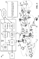
- FIG. 1 is a diagram illustrating an example of a wireless communications system and an access network 100.
- the wireless communications system (also referred to as a wireless wide area network (WWAN)) includes base stations 102, UEs 104, and an Evolved Packet Core (EPC) 160.
- the base stations 102 may include macro cells (high power cellular base station) and/or small cells (low power cellular base station).
- the macro cells include base stations.
- the small cells include femtocells, picocells, and microcells.
- the base stations 102 (collectively referred to as Evolved Universal Mobile Telecommunications System (UMTS) Terrestrial Radio Access Network (E-UTRAN)) interface with the EPC 160 through backhaul links 132 (e.g., S1 interface).
- the base stations 102 may perform one or more of the following functions: transfer of user data, radio channel ciphering and deciphering, integrity protection, header compression, mobility control functions (e.g., handover, dual connectivity), inter-cell interference coordination, connection setup and release, load balancing, distribution for NAS messages, NAS node selection, synchronization, radio access network (RAN) sharing, multimedia broadcast multicast service (MBMS), subscriber and equipment trace, RAN information management (RIM), paging, positioning, and delivery of warning messages.
- the base stations 102 may communicate directly or indirectly (e.g., through the EPC 160) with each other over backhaul links 134 (e.g., X2 interface).
- the backhaul links 134 may be wired or wireless.
- the base stations 102 may wirelessly communicate with the UEs 104. Each of the base stations 102 may provide communication coverage for a respective geographic coverage area 110. There may be overlapping geographic coverage areas 110. For example, the small cell 102' may have a coverage area 1 10' that overlaps the coverage area 110 of one or more macro base stations 102.
- a network that includes both small cell and macro cells may be known as a heterogeneous network.
- a heterogeneous network may also include Home Evolved Node Bs (eNBs) (HeNBs), which may provide service to a restricted group known as a closed subscriber group (CSG).
- eNBs Home Evolved Node Bs
- CSG closed subscriber group
- the communication links 120 between the base stations 102 and the UEs 104 may include uplink (UL) (also referred to as reverse link) transmissions from a UE 104 to a base station 102 and/or downlink (DL) (also referred to as forward link) transmissions from a base station 102 to a UE 104.
- UL uplink
- DL downlink
- the communication links 120 may use multiple-input and multiple-output (MIMO) antenna technology, including spatial multiplexing, beamforming, and/or transmit diversity.
- MIMO multiple-input and multiple-output
- the communication links may be through one or more carriers.
- the base stations 102/UEs 104 may use spectrum up to Y MHz (e.g., 5, 10, 15, 20, 100 MHz) bandwidth per carrier allocated in a carrier aggregation of up to a total of Yx MHz ( x component carriers) used for transmission in each direction.
- the carriers may or may not be adjacent to each other. Allocation of carriers may be asymmetric with respect to DL and UL (e.g., more or less carriers may be allocated for DL than for UL).
- the component carriers may include a primary component carrier and one or more secondary component carriers.
- a primary component carrier may be referred to as a primary cell (PCell) and a secondary component carrier may be referred to as a secondary cell (SCell).
- PCell primary cell
- SCell secondary cell
- D2D communication link 192 may use the DL/UL WWAN spectrum.
- the D2D communication link 192 may use one or more sidelink channels, such as a physical sidelink broadcast channel (PSBCH), a physical sidelink discovery channel (PSDCH), a physical sidelink shared channel (PSSCH), and a physical sidelink control channel (PSCCH).
- sidelink channels such as a physical sidelink broadcast channel (PSBCH), a physical sidelink discovery channel (PSDCH), a physical sidelink shared channel (PSSCH), and a physical sidelink control channel (PSCCH).
- sidelink channels such as a physical sidelink broadcast channel (PSBCH), a physical sidelink discovery channel (PSDCH), a physical sidelink shared channel (PSSCH), and a physical sidelink control channel (PSCCH).
- sidelink channels such as a physical sidelink broadcast channel (PSBCH), a physical sidelink discovery channel (PSDCH), a physical sidelink shared channel (PSSCH), and a physical sidelink control channel (PSCCH).
- the wireless communications system may further include a Wi-Fi access point (AP) 150 in communication with Wi-Fi stations (STAs) 152 via communication links 154 in a 5 GHz unlicensed frequency spectrum.
- AP Wi-Fi access point
- STAs Wi-Fi stations
- communication links 154 in a 5 GHz unlicensed frequency spectrum.
- the STAs 152/AP 150 may perform a clear channel assessment (CCA) prior to communicating in order to determine whether the channel is available.
- CCA clear channel assessment
- the small cell 102' may operate in a licensed and/or an unlicensed frequency spectrum. When operating in an unlicensed frequency spectrum, the small cell 102' may employ NR and use the same 5 GHz unlicensed frequency spectrum as used by the Wi-Fi AP 150. The small cell 102', employing NR in an unlicensed frequency spectrum, may boost coverage to and/or increase capacity of the access network.
- the gNodeB (gNB) 180 may operate in millimeter wave (mmW) frequencies and/or near mmW frequencies in communication with the UE 104.
- mmW millimeter wave
- the gNB 180 may be referred to as an mmW base station.
- Extremely high frequency (EHF) is part of the RF in the electromagnetic spectrum. EHF has a range of 30 GHz to 300 GHz and a wavelength between 1 millimeter and 10 millimeters. Radio waves in the band may be referred to as a millimeter wave.
- Near mmW may extend down to a frequency of 3 GHz with a wavelength of 100 millimeters.
- the super high frequency (SHF) band extends between 3 GHz and 30 GHz, also referred to as centimeter wave. Communications using the mmW / near mmW radio frequency band has extremely high path loss and a short range.
- the mmW base station 180 may utilize beamforming 184 with the UE 104 to compensate for the extremely high path loss and short range.
- the EPC 160 may include a MME 162, other MMEs 164, a Serving Gateway 166, a Multimedia Broadcast Multicast Service (MBMS) Gateway 168, a Broadcast Multicast Service Center (BM-SC) 170, and a PDN Gateway 172.
- the MME 162 may be in communication with a Home Subscriber Server (HSS) 174.
- HSS Home Subscriber Server
- the MME 162 is the control node that processes the signaling between the UEs 104 and the EPC 160.
- the MME 162 provides bearer and connection management. All user Internet protocol (IP) packets are transferred through the Serving Gateway 166, which itself is connected to the PDN Gateway 172.
- the PDN Gateway 172 provides UE IP address allocation as well as other functions.
- the PDN Gateway 172 and the BM-SC 170 are connected to the IP Services 176.
- the IP Services 176 may include the Internet, an intranet, an IP Multimedia Subsystem (IMS), a PS Streaming Service, and/or other IP services.
- the BM-SC 170 may provide functions for MBMS user service provisioning and delivery.
- the BM-SC 170 may serve as an entry point for content provider MBMS transmission, may be used to authorize and initiate MBMS Bearer Services within a public land mobile network (PLMN), and may be used to schedule MBMS transmissions.
- PLMN public land mobile network
- the MBMS Gateway 168 may be used to distribute MBMS traffic to the base stations 102 belonging to a Multicast Broadcast Single Frequency Network (MBSFN) area broadcasting a particular service, and may be responsible for session management (start/stop) and for collecting eMBMS related charging information.
- MMSFN Multicast Broadcast Single Frequency Network
- the base station may also be referred to as a gNB, Node B, evolved Node B (eNB), an access point, a base transceiver station, a radio base station, a radio transceiver, a transceiver function, a basic service set (BSS), an extended service set (ESS), or some other suitable terminology.
- the base station 102 provides an access point to the EPC 160 for a UE 104.
- Examples of UEs 104 include a cellular phone, a smart phone, a session initiation protocol (SIP) phone, a laptop, a personal digital assistant (PDA), a satellite radio, a global positioning system, a multimedia device, a video device, a digital audio player (e.g., MP3 player), a camera, a game console, a tablet, a smart device, a wearable device, a vehicle, an electric meter, a gas pump, a toaster, or any other similar functioning device.
- Some of the UEs 104 may be referred to as IoT devices (e.g., parking meter, gas pump, toaster, vehicles, etc.).
- the UE 104 may also be referred to as a station, a mobile station, a subscriber station, a mobile unit, a subscriber unit, a wireless unit, a remote unit, a mobile device, a wireless device, a wireless communications device, a remote device, a mobile subscriber station, an access terminal, a mobile terminal, a wireless terminal, a remote terminal, a handset, a user agent, a mobile client, a client, or some other suitable terminology.
- the UE 104 or the network may be configured to manage (198) registration rejection due to CloT feature incompatibility. Details of the operations performed at 198 will be further described below with respect to FIGS. 4-12 .
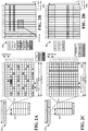
- FIG. 2A is a diagram 200 illustrating an example of a DL frame structure in LTE.
- FIG. 2B is a diagram 230 illustrating an example of channels within the DL frame structure in LTE.
- FIG. 2C is a diagram 250 illustrating an example of an UL frame structure in LTE.
- FIG. 2D is a diagram 280 illustrating an example of channels within the UL frame structure in LTE.
- Other wireless communication technologies may have a different frame structure and/or different channels.
- a frame (10 ms) may be divided into 10 equally sized subframes. Each subframe may include two consecutive time slots.
- a resource grid may be used to represent the two time slots, each time slot including one or more time concurrent resource blocks (RBs) (also referred to as physical RBs (PRBs)).
- RBs time concurrent resource blocks
- PRBs physical RBs
- the resource grid is divided into multiple resource elements (REs).
- REs resource elements
- an RB contains 12 consecutive subcarriers in the frequency domain and 7 consecutive symbols (for DL, OFDM symbols; for UL, SC-FDMA symbols) in the time domain, for a total of 84 REs.
- an RB contains 12 consecutive subcarriers in the frequency domain and 6 consecutive symbols in the time domain, for a total of 72 REs.
- the number of bits carried by each RE depends on the modulation scheme.
- the DL-RS may include cell-specific reference signals (CRS) (also sometimes called common RS), UE-specific reference signals (UE-RS), and channel state information reference signals (CSI-RS).
- CRS cell-specific reference signals
- UE-RS UE-specific reference signals
- CSI-RS channel state information reference signals
- FIG. 2A illustrates CRS for antenna ports 0, 1, 2, and 3 (indicated as R 0 , R 1 , R 2 , and R 3 , respectively), UE-RS for antenna port 5 (indicated as R 5 ), and CSI-RS for antenna port 15 (indicated as R).
- FIG. 2B illustrates an example of various channels within a DL subframe of a frame.
- the physical control format indicator channel (PCFICH) is within symbol 0 of slot 0, and carries a control format indicator (CFI) that indicates whether the physical downlink control channel (PDCCH) occupies 1, 2, or 3 symbols ( FIG. 2B illustrates a PDCCH that occupies 3 symbols).
- the PDCCH carries downlink control information (DCI) within one or more control channel elements (CCEs), each CCE including nine RE groups (REGs), each REG including four consecutive REs in an OFDM symbol.
- DCI downlink control information
- CCEs control channel elements
- Each CCE including nine RE groups (REGs), each REG including four consecutive REs in an OFDM symbol.
- a UE may be configured with a UE-specific enhanced PDCCH (ePDCCH) that also carries DCI.
- the ePDCCH may have 2, 4, or 8 RB pairs ( FIG. 2B shows two RB pairs, each subset including one RB pair).
- the physical hybrid automatic repeat request (ARQ) (HARQ) indicator channel (PHICH) is also within symbol 0 of slot 0 and carries the HARQ indicator (HI) that indicates HARQ acknowledgement (ACK) / negative ACK (NACK) feedback based on the physical uplink shared channel (PUSCH).
- the primary synchronization channel (PSCH) is within symbol 6 of slot 0 within subframes 0 and 5 of a frame, and carries a primary synchronization signal (PSS) that is used by a UE to determine subframe timing and a physical layer identity.
- the secondary synchronization channel is within symbol 5 of slot 0 within subframes 0 and 5 of a frame, and carries a secondary synchronization signal (SSS) that is used by a UE to determine a physical layer cell identity group number. Based on the physical layer identity and the physical layer cell identity group number, the UE can determine a physical cell identifier (PCI). Based on the PCI, the UE can determine the locations of the aforementioned DL-RS.
- the physical broadcast channel (PBCH) is within symbols 0, 1, 2, 3 of slot 1 of subframe 0 of a frame, and carries a master information block (MIB).
- the MIB provides a number of RBs in the DL system bandwidth, a PHICH configuration, and a system frame number (SFN).
- the physical downlink shared channel (PDSCH) carries user data, broadcast system information not transmitted through the PBCH such as system information blocks (SIBs), and paging messages.
- SIBs system information blocks
- some of the REs carry demodulation reference signals (DM-RS) for channel estimation at the eNB.
- the UE may additionally transmit sounding reference signals (SRS) in the last symbol of a subframe.
- SRS sounding reference signals
- the SRS may have a comb structure, and a UE may transmit SRS on one of the combs.
- the SRS may be used by an eNB for channel quality estimation to enable frequency-dependent scheduling on the UL.
- FIG. 2D illustrates an example of various channels within an UL subframe of a frame.
- a physical random access channel (PRACH) may be within one or more subframes within a frame based on the PRACH configuration.
- the PRACH may include six consecutive RB pairs within a subframe.
- PRACH physical random access channel
- the PRACH allows the UE to perform initial system access and achieve UL synchronization.
- a physical uplink control channel may be located on edges of the UL system bandwidth.
- the PUCCH carries uplink control information (UCI), such as scheduling requests, a channel quality indicator (CQI), a precoding matrix indicator (PMI), a rank indicator (RI), and HARQ ACK/NACK feedback.
- UCI uplink control information
- the PUSCH carries data, and may additionally be used to carry a buffer status report (BSR), a power headroom report (PHR), and/or UCI.
- BSR buffer status report
- PHR power headroom report
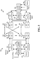
- FIG. 3 is a block diagram of an eNB 310 in communication with a UE 350 in an access network.
- IP packets from the EPC 160 may be provided to a controller/processor 375.
- the controller/processor 375 implements layer 3 and layer 2 functionality.
- Layer 3 includes a radio resource control (RRC) layer
- layer 2 includes a packet data convergence protocol (PDCP) layer, a radio link control (RLC) layer, and a medium access control (MAC) layer.
- RRC radio resource control
- PDCP packet data convergence protocol
- RLC radio link control
- MAC medium access control
- the controller/processor 375 provides RRC layer functionality associated with broadcasting of system information (e.g., MIB, SIBs), RRC connection control (e.g., RRC connection paging, RRC connection establishment, RRC connection modification, and RRC connection release), inter radio access technology (RAT) mobility, and measurement configuration for UE measurement reporting; PDCP layer functionality associated with header compression / decompression, security (ciphering, deciphering, integrity protection, integrity verification), and handover support functions; RLC layer functionality associated with the transfer of upper layer packet data units (PDUs), error correction through ARQ, concatenation, segmentation, and reassembly of RLC service data units (SDUs), re-segmentation of RLC data PDUs, and reordering of RLC data PDUs; and MAC layer functionality associated with mapping between logical channels and transport channels, multiplexing of MAC SDUs onto transport blocks (TBs), demuliplexing of MAC SDUs from TBs, scheduling information reporting, error
- the transmit (TX) processor 316 and the receive (RX) processor 370 implement layer 1 functionality associated with various signal processing functions.
- Layer 1 which includes a physical (PHY) layer, may include error detection on the transport channels, forward error correction (FEC) coding/decoding of the transport channels, interleaving, rate matching, mapping onto physical channels, modulation/demodulation of physical channels, and MIMO antenna processing.
- the TX processor 316 handles mapping to signal constellations based on various modulation schemes (e.g., binary phase-shift keying (BPSK), quadrature phase-shift keying (QPSK), M-phase-shift keying (M-PSK), M-quadrature amplitude modulation (M-QAM)).
- BPSK binary phase-shift keying
- QPSK quadrature phase-shift keying
- M-PSK M-phase-shift keying
- M-QAM M-quadrature amplitude modulation
- Each stream may then be mapped to an OFDM subcarrier, multiplexed with a reference signal (e.g., pilot) in the time and/or frequency domain, and then combined together using an Inverse Fast Fourier Transform (IFFT) to produce a physical channel carrying a time domain OFDM symbol stream.
- the OFDM stream is spatially precoded to produce multiple spatial streams.
- Channel estimates from a channel estimator 374 may be used to determine the coding and modulation scheme, as well as for spatial processing.
- the channel estimate may be derived from a reference signal and/or channel condition feedback transmitted by the UE 350.
- Each spatial stream may then be provided to a different antenna 320 via a separate transmitter 318TX.
- Each transmitter 318TX may modulate an RF carrier with a respective spatial stream for transmission.
- each receiver 354RX receives a signal through its respective antenna 352.
- Each receiver 354RX recovers information modulated onto an RF carrier and provides the information to the receive (RX) processor 356.
- the TX processor 368 and the RX processor 356 implement layer 1 functionality associated with various signal processing functions.
- the RX processor 356 may perform spatial processing on the information to recover any spatial streams destined for the UE 350. If multiple spatial streams are destined for the UE 350, they may be combined by the RX processor 356 into a single OFDM symbol stream.
- the RX processor 356 then converts the OFDM symbol stream from the time-domain to the frequency domain using a Fast Fourier Transform (FFT).
- FFT Fast Fourier Transform
- the frequency domain signal comprises a separate OFDM symbol stream for each subcarrier of the OFDM signal.
- the symbols on each subcarrier, and the reference signal, are recovered and demodulated by determining the most likely signal constellation points transmitted by the eNB 310. These soft decisions may be based on channel estimates computed by the channel estimator 358.
- the soft decisions are then decoded and deinterleaved to recover the data and control signals that were originally transmitted by the eNB 310 on the physical channel.
- the data and control signals are then provided to the controller/processor 359, which implements layer 3 and layer 2 functionality.
- the controller/processor 359 can be associated with a memory 360 that stores program codes and data.
- the memory 360 may be referred to as a computer-readable medium.
- the controller/processor 359 provides demultiplexing between transport and logical channels, packet reassembly, deciphering, header decompression, and control signal processing to recover IP packets from the EPC 160.
- the controller/processor 359 is also responsible for error detection using an ACK and/or NACK protocol to support HARQ operations.
- the controller/processor 359 provides RRC layer functionality associated with system information (e.g., MIB, SIBs) acquisition, RRC connections, and measurement reporting; PDCP layer functionality associated with header compression / decompression, and security (ciphering, deciphering, integrity protection, integrity verification); RLC layer functionality associated with the transfer of upper layer PDUs, error correction through ARQ, concatenation, segmentation, and reassembly of RLC SDUs, re-segmentation of RLC data PDUs, and reordering of RLC data PDUs; and MAC layer functionality associated with mapping between logical channels and transport channels, multiplexing of MAC SDUs onto TBs, demuliplexing of MAC SDUs from TBs, scheduling information reporting, error correction through HARQ, priority handling, and logical channel prioritization.
- RRC layer functionality associated with system information (e.g., MIB, SIBs) acquisition, RRC connections, and measurement reporting
- PDCP layer functionality associated with header
- Channel estimates derived by a channel estimator 358 from a reference signal or feedback transmitted by the eNB 310 may be used by the TX processor 368 to select the appropriate coding and modulation schemes, and to facilitate spatial processing.
- the spatial streams generated by the TX processor 368 may be provided to different antenna 352 via separate transmitters 354TX. Each transmitter 354TX may modulate an RF carrier with a respective spatial stream for transmission.
- the UL transmission is processed at the eNB 310 in a manner similar to that described in connection with the receiver function at the UE 350.
- Each receiver 318RX receives a signal through its respective antenna 320.
- Each receiver 318RX recovers information modulated onto an RF carrier and provides the information to a RX processor 370.
- the controller/processor 375 can be associated with a memory 376 that stores program codes and data.
- the memory 376 may be referred to as a computer-readable medium.
- the controller/processor 375 provides demultiplexing between transport and logical channels, packet reassembly, deciphering, header decompression, control signal processing to recover IP packets from the UE 350. IP packets from the controller/processor 375 may be provided to the EPC 160.
- the controller/processor 375 is also responsible for error detection using an ACK and/or NACK protocol to support HARQ operations.
- CloT is a type of wireless communication technology that may provide certain CloT features at the upper layer (e.g., NAS layer).
- a non-exhaustive list of CloT features may include data transfer over the control plane (e.g., CP CloT optimization), a suspend mode / resume mode of operation when data is sent over a user plane (e.g., UP CloT optimization), network attachment without PDN connectivity (e.g., EMM-REGISTERED without PDN connection), and support for SMS without attaching to both CS services and PS services (e.g., combined attach).
- CS services and PS services may be independent of one another, CS services and PS services may or may not be concurrently supported by a UE and/or by the a core network entity.
- the core network entity that manages the CS services and PS services may be a MME.
- a UE When a UE attempts register with a network and use one or more of the CloT features, the UE may indicate in a registration request (e.g., that is sent to a core network entity) which of the CloT features UE intends to use.
- Registration as used herein may mean an attach procedure or a TA update procedure.
- a "registration request” and/or a “registration reject message” as used herein may mean sending an attach request message, an attach reject message, a Tracking Area Update (TAU) request message, and/or a TAU reject message.
- a "cause value” as used herein may mean a cause information element (IE).
- a registration request sent by the UE may indicate that the UE supports an attach procedure without PDN connectivity, CP CloT optimization, and UP CloT optimization.
- the registration request may indicate that the UE would like to use the CP CloT optimization.
- the core network entity may maintain a list of supported CloT features by the core network entity and requested CloT features associated with the UE.
- the core network entity may determine if the CloT feature(s) (e.g., CP CloT optimization) requested by the UE are supported by the core network entity, and if so, the core network entity may accept the registration request. If the core network entity does not support the requested feature(s) (e.g., CP CloT optimization), but the core network entity supports one of the UE's requested CloT features, the core network entity may accept the registration request.
- the CloT feature(s) e.g., CP CloT optimization
- the core network entity may accept the registration request.
- the core network entity may send a registration reject message that rejects the registration of the UE.
- the core network entity may send a registration reject message that rejects the registration of the UE.
- the UE may continue to attempt to attach to the current PLMN and/or TA, which may increase the time needed by the UE to attach to the network.
- CloT feature incompatibility may not be detected by the network.
- CloT feature incompatibility may be detected based on the SIB indications by the network 1) when a UE requests SMS without combined attach and the network does not support SMS without combined attach, and 2) when the UE operates in WB-S1 mode and supports only S1-U data transfer, and the network does not support S1-U data transfer.
- SIB indications about the network support for CloT optimizations represent a rare case of core network capabilities advertised in the radio network.
- the SIB indications may require a coordinated deployment of CloT features across the radio network and the core network. Therefore, the need to reject the registration request due to CloT feature incompatibility between the network and the UE may need to be addressed in the scenarios in which SIB indications are provided by the network.
- the present disclosure provides a solution to the problems discussed above by including a cause value in the registration reject message.
- the cause value may cause the UE to attach to a PLMN and/or TA that supports the UE's CloT features.
- the information associated with the UE's requested CloT features and UE supported CloT features included in the registration request may indicate a preferred network behavior to the core network entity. If the preferred network behavior (e.g., the UE's supported CloT features included in the registration request) included in the registration request is incompatible with the core network entity's supported CloT features (e.g., the UE indicates support for CP CloT optimization and the core network entity only supports UP CloT optimization), the core network entity may reject the registration reject message with an appropriate cause value (e.g., a cause value that avoids attempting to register on the current PLMN and/or the current TA).
- an appropriate cause value e.g., a cause value that avoids attempting to register on the current PLMN and/or the current TA.
- a first cause value may be included in the registration reject message to cause the UE to select another PLMN.
- a second cause value may be included in the registration reject message to cause the UE to select another TA in the same PLMN
- backward compatibility issues may be reduced (e.g., the ability of legacy UEs to be able to function by using legacy techniques by ignoring new features while new UEs may be able to take advantage of the new features), the development effort for CloT networks may be reduced, undefined UE behavior may be reduced, and the time spent retrying unsuccessful registration attempts and time searching for a network that can accept the registration request may be reduced.
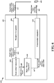
- FIG. 4 is a diagram illustrating an example of handling the incompatibility between features supported by the device and the network in a wireless communication system 400.
- the wireless communication system 400 may include a UE 406 (e.g., the UE 104, 350, 406, 650, apparatus 902/902') and a core network entity 402 (e.g., the MME 162, the core network entity 402, 950, the apparatus 602/602', a core network entity in a 5G NR network).
- a UE 406 e.g., the UE 104, 350, 406, 650, apparatus 902/902'
- a core network entity 402 e.g., the MME 162, the core network entity 402, 950, the apparatus 602/602', a core network entity in a 5G NR network.
- the UE 406 may send a registration request including a request for CloT features to the core network entity 402.
- the CloT optimization features that may be indicated in the registration request include support for an attach procedure without PDN connectivity, CP CloT optimization, UP CloT optimization, SMS without combined attach, and/or S1-U data transfer.
- the core network entity 402 may determine to reject the registration request from the UE 406. In one configuration, the core network entity 402 may determine whether there is compatibility between the UE's requested CloT features and the core network entity's 402 supported CloT features. If there is no CloT feature compatibility between the UE 406 and the core network entity 402, the core network entity 402 may determine to reject the registration request.
- the core network entity 402 may indicate to one or more UEs which CloT features are supported by the core network entity 402 in a SIB (e.g., a SIB indication that is broadcast or transmitted to surrounding UEs).
- a SIB e.g., a SIB indication that is broadcast or transmitted to surrounding UEs.
- the CloT feature incompatibility between the core network entity 402 and the UE 406 may not be detected based on the SIB indications.
- the scenarios in which the CloT feature incompatibility may not be detected include 1) when the network does not support SMS without combined attach requested by the UE and 2) when the network does not support S1-U data transfer, and the UE operates in WB-S1 mode and only supports S1-U data transfer.
- SIB indications indicating supported CloT features may represent a case of radio network capabilities advertised in the network.
- the SIB indications may use a fully coordinated deployment of CloT features across a radio network and the core network.
- the SIB indications may not be an essential or even required feature from the point of view of the radio network.
- the radio network may include base stations (e.g., cells) communicating over the air with the UEs.
- the base stations may be connected to the core network (e.g., over wireline) which may include network entities (e.g., MME, HSS, etc.).
- the core network may manage subscription data, access control, etc., and communicate with an external network (e.g., the internet).
- the core network entity 402 may select a cause value to be included in the registration reject message.
- the core network entity 402 may determine which cause value to include in the registration reject message based on one or more of 1) whether the UE 406 is in narrowband (NB) S1 (NB-S1) mode or in wide band (WB) S1 (WB-S1) mode (e.g., the core network entity 402 may receive information from the radio network that indicates whether the UE 406 operates in NB-S1 mode or WB-S1 mode), 2) knowledge of the supported CloT features in local deployment, such as availability of another tracking area (e.g., in another frequency) in the same area of the current PLMN that the UE 406 could attempt to register with etc., and/or 3) other information available in the core network entity 402.
- the core network entity 402 may set the EMM cause value to #15 indicating "No suitable cells in tracking area”. If the core network entity 402 determines that the UE 406 needs to search for another PLMN (e.g., rather than search for a suitable cell in another TA of the current PLMN) the core network entity 402 may include the Extended EMM cause IE with a value that indicates the "requested EPS optimization not supported”.
- the core network entity 402 may include the Extended EMM cause IE with a value that indicates the "requested EPS optimization not supported”.
- the core network entity 402 may include a cause value in the registration reject message that causes the UE 406 to select another network (e.g., another PLMN).
- a cause value #15 with Extended EMM cause IE set to "requested EPS optimization not supported" (e.g., a new value) may be included in the registration reject message by the core network entity 402.
- a new cause value (e.g., a new cause value #xy) that indicates that the "requested EPS optimization not supported" may be selected by the core network entity 402 and included in the registration reject message.
- One advantage associated with the first configuration may be that cause value #15 with Extended EMM cause IE set to "requested EPS optimization not supported" is backward compatible with legacy UE's. Namely, legacy UE's may ignore the new value in the Extended EMM cause IE set to "requested EPS optimization not supported," and use legacy behavior corresponding to cause value #15.
- One advantage associated with the second configuration may include that the new cause value #xy may be used to define fully dedicated UE behavior. Table 1 seen below includes additional details with respect to Extended EMM cause IEs.
- E-UTRAN allowed value (octet 1, bit 1) Bit 1 0 E-UTRAN allowed 1 E-UTRAN not allowed EPS optimization info (octet 1, bit 2) Bit 2 0 no EPS optimization info 1 requested EPS optimization not supported Bit 3 and bit 4 of octet 1 are spare and shall be coded as zero. Bit 1 and bit 2 of octet 1 shall not be set to 1 simultaneously.
- an Extended EMM cause IE may contain a bitmap where certain bits are used to convey specific info to the UE 406.
- bit 2 in octet 1 of the Extended EMM cause IE may be used to indicate to the UE 406 whether the registration reject message is due to the CIOT features requested by the UE40 not being supported by the network.
- the Extended EMM cause IE does not contain any specific info as to the reason for the rejection.
- the bit is set to '1', the rejection is due to due to the CloT features requested by the UE 406 not being supported by the network.
- the core network entity 402 may select a cause value that causes the UE 406 to select another TA in the same network (e.g., the current PLMN). For example cause value #15 without Extended EMM cause value set to "requested EPS optimization not supported" or to a new cause value (e.g., new cause value #xy) dedicated to this rejection scenario may be selected.
- the core network entity 402 may send the registration reject message including the selected cause value to the UE 406.
- the UE 406 may determine its behavior based on the cause value included in the registration reject message. Depending on the received cause value in the registration reject message, the UE 406 may search for another TA (e.g., when cause value #15 is received without the Extended EMM cause value set to "requested EPS optimization not supported"), or search for another PLMN (e.g., when cause value #15 is received with Extended EMM cause value set to "requested EPS optimization not supported"). In another example, the UE 406 may search for another TA when an existing cause value (e.g., #15) is received (with optional Extended EMM cause value), and search for another PLMN when the new cause value (e.g., #xy) is received.
- an existing cause value e.g., #15
- the new cause value e.g., #xy
- the UE may search for another TA in the same PLMN by searching and/or scanning for other available cells that are in a different TA (e.g., the TA to which a cell belongs may be indicated in the SIB broadcast by the cell).
- Causing the UE 406 to search for another TA may be useful in the multi-frequency deployments found in legacy LTE networks, in which multiple frequency layers overlap in coverage providing overlapping TAs on different frequencies.
- NB-IoT may not be deployed over multiple frequency layers.
- a UE 406 operating in NB-S1 mode may be unlikely to find suitable NB-IoT cells in other TAs.
- the UE 406 may perform a search for a new PLMN rather than waste time looking for a suitable cell in another TA of the same PLMN
- the new Extended EMM cause IE included with the cause value #15 may result in the UE 406 searching for a new PLMN.
- the core network entity 402 may provide the new Extended EMM cause IE with the cause value #15 to the UE 406 when the core network entity 402 determines that the UE 406 will not find a suitable cell in another TA of the same PLMN compatible with the UE's 406 supported CloT features.
- the determination by the core network entity 402 may be based on the UE's 406 mode (i.e. NB-S1 vs. WB-S1), deployment knowledge (e.g.
- the core network entity 402 may provide the legacy cause value #15 without Extended EMM cause IE and the UE 406 may follow the legacy behavior for cause value #15.
- the UE's 406 behavior may be based on the UE's mode of operation (e.g., NB-S1 mode or WB-S1 mode). For example, upon receiving the registration reject message, a UE 406 in NB-S1 mode may search for a new PLMN upon receiving the registration reject message, whereas a UE 406 in WB-S1 mode behaves according to the legacy cause value #15 (e.g., searches for a suitable cell in another TA of the same PLMN first).
- the legacy cause value #15 e.g., searches for a suitable cell in another TA of the same PLMN first.
- the UE 406 may place the current PLMN and/or the current TA where the registration rejection message was received in a list of forbidden PLMNs and/or TAs. Forbidden PLMNs and/or TAs may not be selected by the UE 406 in a subsequent search for a certain time period. The list of forbidden PLMNs and/or TAs may be erased after the certain time period, or upon power cycling at the UE 406 or when the Subscriber Identity Module (SIM) card at the UE 406 is removed.
- SIM Subscriber Identity Module
- the forbidden list may be stored in the UE 406 or in the SIM card at the UE 406.
- the UE 406 may place the current PLMN+RAT or TA+RAT combination in the forbidden list.
- RATs include NB-IoT, WB-E-UTRAN, UTRAN, GERAN, etc.
- the UE 406 may 1) delete a list of equivalent PLMNs and set an attach attempt counter to a predetermined value (e.g., a value of five), 2) enter a state "EMM-DEREGISTERED.PLMN-SEARCH” in order to perform a new PLMN selection, and 3) not consider the PLMN that provided the registration rejection message a candidate for PLMN selection until the UE 406 is switched off or the Universal Integrated Circuit Card (UICC) containing the Universal SIM (USIM) card is removed.
- a predetermined value e.g., a value of five
- the list of equivalent PLMNs may be sent by the network entity 402 to the UE 406 when the UE 406 registers with the network entity 402.
- the equivalent PLMNs may be considered by the UE 406 as "equivalent" to the registered PLMN, which means the UE 406 may move between the equivalent PLMNs via cell reselection and Tracking Area Update procedure, without the need to perform PLMN selection and Attach procedure (e.g., a more involved process than cell reselection).
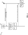
- FIG. 5 is a flowchart 500 of a method of wireless communication.
- the method may be performed by a core network entity (e.g., the MME 162, the core network entity 402, 950, the apparatus 602/602') in communication with a UE (e.g., the UE 104, 350, 406, 650, apparatus 902/902').
- a core network entity e.g., the MME 162, the core network entity 402, 950, the apparatus 602/602'
- a UE e.g., the UE 104, 350, 406, 650, apparatus 902/902'.
- the core network entity may receive a registration request including requested features from a UE.
- the requested features may include CloT optimization features.
- the CloT optimization features may include at least a requested EPS optimization.
- the core network entity may be an MME.
- the UE 406 may send a registration request including a request for CloT features to the core network entity 402.
- the CloT features that may be indicated in the registration request include support for an attach procedure without PDN connectivity, CP CloT optimization, UP CloT optimization, SMS without combined attach, and/or S1-U data transfer.
- the core network entity may determine to reject the registration request based on the requested features. For example, referring to FIG. 4 , at 412, the core network entity 402 may determine to reject the registration request from the UE 406. In one configuration, the core network entity 402 may determine whether there is compatibility between the UE's requested CloT features and the core network entity's 402 supported CloT features. If there is no CloT feature compatibility between the UE 406 and the core network entity 402, the core network entity 402 may determine to reject the registration request.
- the MME may select a cause value from a plurality of cause values to include in a registration reject message to the UE.
- the plurality of cause values may include at least a first cause value and a second cause value.
- the first cause value may include a cause value number.
- the second cause value includes an Extended EMM cause information element.
- the cause value number may be cause value #15.
- the first cause value may indicate that there are no suitable cells in a tracking area.
- the second cause value may indicate that the requested EPS optimization is not supported.
- the cause value may be selected based on whether the UE is in NB-S1 mode or WB-S1 mode In certain other aspects, the cause value may be selected based on knowledge of local deployment. In certain other aspects, the knowledge of the local deployment may include whether the local deployment is such that there exists another tracking area in another frequency in a same area of a current PLMN.
- the first cause value may instruct the UE to search for another tracking area worthy of attempting registration in a current PLMN and the first cause value instructs the UE to attempt to find a suitable cell in another tracking area of the current PLMN
- the second cause value may indicate that the UE will not find another tracking area worthy of attempting registration in the current PLMN and the second cause value may instruct the UE to attempt to find a different PLMN
- the cause value number may indicate whether the UE can find another tracking area worthy of attempting registration in the current PLMN In certain other aspects, the cause value number may indicate that the CloT optimization features are not supported in the current PLMN. For example, referring to FIG. 4 , at 416, the core network entity 402 may select a cause value to be included in the registration reject message.
- the core network entity 402 may determine which cause value to include in the registration reject message based on one or more of 1) whether the UE 406 is in NB-S1 mode or in wide band WB-S1 mode (e.g., the core network entity 402 may receive information from the radio network that indicates whether the UE 406 operates in NB-S1 mode or WB-S1 mode), 2) knowledge of the supported CloT features in local deployment, such as availability of another tracking area (e.g., in another frequency) in the same area of the current PLMN that the UE 406 could attempt to register with etc., and/or 3) other information available in the core network entity 402.
- 1) whether the UE 406 is in NB-S1 mode or in wide band WB-S1 mode e.g., the core network entity 402 may receive information from the radio network that indicates whether the UE 406 operates in NB-S1 mode or WB-S1 mode
- 2) knowledge of the supported CloT features in local deployment such as availability of another tracking area (e.g
- the core network entity 402 may set the EMM cause value to #15 indicating "No suitable cells in tracking area”. If the core network entity 402 determines that the UE 406 needs to search for another PLMN (e.g., rather than search for a suitable cell in another TA of the current PLMN) the core network entity 402 may include the Extended EMM cause IE with a value that indicates that "requested EPS optimization not supported”.
- the core network entity 402 may include the Extended EMM cause IE with a value that indicates that "requested EPS optimization not supported”.
- the core network entity 402 may include a cause value in the registration reject message that causes the UE 406 to select another network (e.g., another PLMN).
- a cause value #15 with Extended EMM cause IE set to "requested EPS optimization not supported" e.g., a new value
- a new cause value (e.g., a new cause value #xy) that indicates that the "requested EPS optimization not supported” may be selected by the core network entity 402 and included in the rejection reject message.
- a new cause value #xy may be selected by the core network entity 402 and included in the rejection reject message.
- One advantage associated with the first configuration may be that cause value #15 with Extended EMM cause IE set to "requested EPS optimization not supported" is backward compatible with legacy UE's. Namely, legacy UE's may ignore the new value in the Extended EMM cause IE set to "requested EPS optimization not supported," and use legacy behavior corresponding to cause value #15.
- the new cause value #xy may be used to define fully dedicated UE behavior.
- the core network entity 402 may select a cause value that causes the UE 406 to select another TA in the same network (e.g., the current PLMN). For example cause value #15 without Extended EMM cause value set to "requested EPS optimization not supported" or a new cause value (e.g., new cause value #xy) dedicated to this rejection scenario may be selected.
- the core network entity may send the registration reject message to the UE.
- the core network entity 402 may send the registration reject message including the selected cause value to the UE 406.
- FIG. 6 is a conceptual data flow diagram 600 illustrating the data flow between different means/components in an exemplary apparatus 602.
- the apparatus may be a core network entity (e.g., the MME 162, the core network entity 402, 950, the apparatus 602') in communication with a UE 650 (e.g., the UE 104, 350, 406, 650, apparatus 902/902').
- the apparatus may include a reception component 604, a registration component 606, a reject message component 608, and a transmission component 610.
- the reception component 604 may be configured to receive a registration request 601 including requested features from the UE 650.
- the requested features may include CloT optimization features.
- the CloT optimization features may include at least a requested EPS optimization.
- the reception component 604 may be configured to send a signal 603 associated with the registration request that includes the requested features (e.g., CloT optimization features) to the registration component 606.
- the registration component 606 may be configured to determine to reject the registration request based on the requested features. For example, the registration component 606 may compare the requested features to the features supported by the network of the apparatus 602, and determine to reject the registration request when it is determined that the requested CloT features are incompatible with the network. The registration component 606 may be configured to send a signal 605 indicating that the registration request is rejected to the reject message component 608.
- the reject message component 608 may be configured to select a cause value from a plurality of cause values to include in a registration reject message to the UE.
- the plurality of cause values may include at least a first cause value and a second cause value.
- the first cause value may include a cause value number.
- the second cause value includes an Extended EMM cause information element.
- the cause value number may be cause value #15.
- the first cause value may indicate that there are no suitable cells in a tracking area.
- the second cause value may indicate that the requested EPS optimization is not supported.
- the cause value may be selected based on whether the UE is in NB-S1 mode or WB-S1 mode.
- the cause value may be selected based on knowledge of local deployment.
- the knowledge of the local deployment may include whether the local deployment is such that there exists another tracking area in another frequency in a same area of a current PLMN
- the first cause value may instruct the UE to search for another tracking area worthy of attempting registration in a current PLMN and the first cause value instructs the UE to attempt to find a suitable cell in another tracking area of the current PLMN.
- the second cause value may indicate that the UE will not find another tracking area worthy of attempting registration in the current PLMN and the second cause value may instruct the UE to attempt to find a different PLMN
- the cause value number may indicate that the CloT optimization features are not supported in the current PLMN
- the reject message component 608 may be configured to generate a registration reject message that includes the cause value.
- the reject message component 608 may be configured to send a signal 607 associated with the registration reject message that includes the cause value to the transmission component 610.
- the transmission component 610 may be configured to send the registration reject message 609 to the UE 650.
- the apparatus may include additional components that perform each of the blocks of the algorithm in the aforementioned flowchart of FIG. 5 .
- each block in the aforementioned flowchart of FIG. 5 may be performed by a component and the apparatus may include one or more of those components.
- the components may be one or more hardware components specifically configured to carry out the stated processes/algorithm, implemented by a processor configured to perform the stated processes/algorithm, stored within a computer-readable medium for implementation by a processor, or some combination thereof.
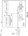
- FIG. 7 is a diagram 700 illustrating an example of a hardware implementation for an apparatus 602' employing a processing system 714.
- the processing system 714 may be implemented with a bus architecture, represented generally by the bus 724.
- the bus 724 may include any number of interconnecting buses and bridges depending on the specific application of the processing system 714 and the overall design constraints.
- the bus 724 links together various circuits including one or more processors and/or hardware components, represented by the processor 704, the components 604, 606, 608, 610 and the computer-readable medium / memory 706.
- the bus 724 may also link various other circuits such as timing sources, peripherals, voltage regulators, and power management circuits, which are well known in the art, and therefore, will not be described any further.
- the processing system 714 may be coupled to a transceiver 710.
- the transceiver 710 is coupled to one or more antennas 720.
- the transceiver 710 provides a means for communicating with various other apparatus over a transmission medium.
- the transceiver 710 receives a signal from the one or more antennas 720, extracts information from the received signal, and provides the extracted information to the processing system 714, specifically the reception component 604.
- the transceiver 710 receives information from the processing system 714, specifically the transmission component 610, and based on the received information, generates a signal to be applied to the one or more antennas 720.
- the processing system 714 includes a processor 704 coupled to a computer-readable medium / memory 706.
- the processor 704 is responsible for general processing, including the execution of software stored on the computer-readable medium / memory 706.
- the software when executed by the processor 704, causes the processing system 714 to perform the various functions described supra for any particular apparatus.
- the computer-readable medium / memory 706 may also be used for storing data that is manipulated by the processor 704 when executing software.
- the processing system 714 further includes at least one of the components 604, 606, 608, 610.
- the components may be software components running in the processor 704, resident/stored in the computer readable medium / memory 706, one or more hardware components coupled to the processor 704, or some combination thereof.
- the apparatus 602/602' for wireless communication may include means for receiving a registration request including requested features from a UE.
- the requested features may include CloT optimization features.
- the CloT optimization features may include at least a requested EPS optimization.
- the core network entity may be an MME.
- the apparatus 602/602' for wireless communication may include means for determining to reject the registration request based on the requested features.
- the apparatus 602/602' for wireless communication may include means for selecting a cause value from a plurality of cause values to include in a registration reject message to the UE.
- the plurality of cause values may include at least a first cause value and a second cause value.
- the first cause value may include a cause value number.
- the second cause value includes an Extended EMM cause information element.
- the cause value number may be cause value #15.
- the first cause value may indicate that there are no suitable cells in a tracking area.
- the second cause value may indicate that the requested EPS optimization is not supported.
- the cause value may be selected based on whether the UE is in NB-S1 mode or WB-S1 mode. In certain other aspects, the cause value may be selected based on knowledge of local deployment.
- the knowledge of the local deployment may include whether the local deployment is such that there exists another tracking area in another frequency in a same area of a current PLMN
- the first cause value may instruct the UE to search for another tracking area worthy of attempting registration in a current PLMN and the first cause value instructs the UE to attempt to find a suitable cell in another tracking area of the current PLMN.
- the second cause value may indicate that the UE will not find another tracking area worthy of attempting registration in the current PLMN and the second cause value may instruct the UE to attempt to find a different PLMN
- the cause value number may indicate that the CloT optimization features are not supported in the current PLMN
- the apparatus 602/602' for wireless communication may include means for sending the registration reject message to the UE.
- the aforementioned means may be one or more of the aforementioned components of the apparatus 602 and/or the processing system 714 of the apparatus 602' configured to perform the functions recited by the aforementioned means.
- FIG. 8 is a flowchart 800 of a method of wireless communication.
- the method may be performed by a UE (e.g., the UE 104, 350, 406, 650, apparatus 902/902') in communication with a core network entity (e.g., the MME 162, the core network entity 402, 950, the apparatus 602/602').
- a UE e.g., the UE 104, 350, 406, 650, apparatus 902/902'
- a core network entity e.g., the MME 162, the core network entity 402, 950, the apparatus 602/602'.
- operations indicated with dashed lines indicate optional operations.
- the UE may transmit a registration request including requested CloT features to a core network entity.
- the requested features may include CloT optimization features.
- the CloT optimization features may include at least a requested EPS optimization.
- the UE 406 may send a registration request including a request for CloT features to the core network entity 402.
- the CloT features that may be indicated in the registration request include support for an attach procedure without PDN connectivity, CP CloT optimization, UP CloT optimization, SMS without combined attach, and/or S1-U data transfer.
- the UE may receive a registration reject message including a cause value.
- the cause value may include one of a first cause value or a second cause value.
- the first cause value may include a cause value number.
- the second cause value includes an Extended EMM cause information element.
- the cause value number may be cause value #15.
- the first cause value may indicate that there are no suitable cells in a tracking area.
- the second cause value may indicate that the requested EPS optimization is not supported.
- the cause value number may be dedicated to indicate whether the UE can find another tracking area worthy of attempting registration in the current PLMN In certain other aspects, the cause value number may be dedicated to indicate that the CloT optimization features are not supported in the current PLMN
- the core network entity 402 may send the registration reject message including the selected cause value that is received by the UE 406.
- the UE may determine whether to search for another tracking area of a current PLMN based on the cause value. For example, referring to FIG. 4 , the UE 406 may determine its behavior based on the cause value included in the registration reject message. Depending on the received cause value in the registration reject message, the UE 406 may search for another TA (e.g., when cause value #15 is received without the Extended EMM cause value set to "requested EPS optimization not supported"), or search for another PLMN (e.g., when cause value #15 is received with Extended EMM cause value set to "requested EPS optimization not supported").
- TA e.g., when cause value #15 is received without the Extended EMM cause value set to "requested EPS optimization not supported
- search for another PLMN e.g., when cause value #15 is received with Extended EMM cause value set to "requested EPS optimization not supported
- the UE 406 may search for another TA when an existing cause value (e.g., #15) is received (with optional Extended EMM cause value), and search for another PLMN when the new cause value (e.g., #xy) is received.
- searching for another TA in the same PLMN may include searching for a suitable cell in another TA.
- the new Extended EMM cause IE included with the cause value #15 may result in the UE 406 searching for a new PLMN.
- the core network entity 402 may provide the new Extended EMM cause IE with the cause value #15 to the UE 406 when the core network entity 402 determines that the UE 406 will not find a suitable cell in another TA of the same PLMN compatible with the UE's 406 supported CloT features.
- the determination by the core network entity 402 may be based on the UE's 406 mode (i.e. NB-S1 vs. WB-S1), deployment knowledge (e.g. knowledge that there is another TA on a different frequency in the same area with the CloT feature(s) that the UE 406 wants to use), and potentially other factors.
- the core network entity 402 may provide the legacy cause value #15 without Extended EMM cause IE and the UE 406 follows the legacy behavior for cause value #15.
- the UE's 406 behavior may be dictated based on the UE's mode of operation (e.g., NB-S1 mode or WB-S1 mode).
- a UE 406 in NB-S1 mode may search for a new PLMN right away whereas a UE 406 in WB-S1 mode behaves according to the legacy cause value #15 (e.g., searches for a suitable cell in another TA of the same PLMN first).
- the UE may attempt registration in another tracking area of the current PLMN when the cause value is the first cause value. For example, referring to FIG. 4 , depending on the received cause value in the registration reject message, the UE 406 may attempt registration with another TA (e.g., when cause value #15 is received without the Extended EMM cause value set to "requested EPS optimization not supported"). In another example, the UE 406 may attempt registration with another TA when an existing cause value (e.g., #15) is received (with optional Extended EMM cause value). In one configuration, attempting registration with another TA in the same PLMN may include attempting registration with a suitable cell in another TA.
- another TA e.g., when cause value #15 is received without the Extended EMM cause value set to "requested EPS optimization not supported”
- an existing cause value e.g., #15
- attempting registration with another TA in the same PLMN may include attempting registration with a suitable cell in another TA.
- the UE may attempt to select another PLMN when the cause value is the second cause value. For example, referring to FIG. 4 , depending on the received cause value in the registration reject message, the UE 406 may attempt to select another PLMN (e.g., when cause value #15 is received with Extended EMM cause value set to "requested EPS optimization not supported"). In another example, the UE 406 may attempt to select another PLMN when the new cause value (e.g., #xy) is received.
- the new cause value e.g., #xy
- FIG. 9 is a conceptual data flow diagram 900 illustrating the data flow between different means/components in an exemplary apparatus 902.
- the apparatus may be a UE (e.g., the UE 104, 350, 406, 650, apparatus 902/902') in communication with a core network entity 950 (e.g., the MME 162, the core network entity 402, the apparatus 602').
- the apparatus may include a reception component 904, an operation determination component 906, and a transmission component 908.
- the transmission component 908 may be configured to transmit a registration request 901 including requested features to the core network entity 950.
- the requested features may include CloT optimization features.
- the CloT optimization features may include at least a requested EPS optimization.
- the reception component 904 may be configured to receive a registration reject message 903 including a cause value.
- the cause value may include one of a first cause value or a second cause value.
- the first cause value may include a cause value number.
- the second cause value includes an Extended EMM cause information element.
- the cause value number may be cause value #15.
- the first cause value may indicate that there are no suitable cells in a tracking area.
- the second cause value may indicate that the requested EPS optimization is not supported.
- the cause value number may be dedicated to indicate whether the UE can find another tracking area worthy of attempting registration in the current PLMN.
- the cause value number may be dedicated to indicate that the CloT optimization features are not supported in the current PLMN.
- the reception component 904 may be configured to send a signal 905 associated with the registration reject message including the cause value to the operation determination component 906.
- the operation determination component 906 may be configured to determine whether to search for another tracking area of a current PLMN based on the cause value.
- the operation determination component 906 may be configured to attempt registration in the another tracking area of the current PLMN when the cause value is the first cause value.
- the operation determination component 906 may be configured to attempt to select another PLMN when the cause value is the second cause value.
- the apparatus may include additional components that perform each of the blocks of the algorithm in the aforementioned flowchart of FIG. 8 .
- each block in the aforementioned flowchart of FIG. 8 may be performed by a component and the apparatus may include one or more of those components.
- the components may be one or more hardware components specifically configured to carry out the stated processes/algorithm, implemented by a processor configured to perform the stated processes/algorithm, stored within a computer-readable medium for implementation by a processor, or some combination thereof.
- FIG. 10 is a diagram 1000 illustrating an example of a hardware implementation for an apparatus 902' employing a processing system 1014.
- the processing system 1014 may be implemented with a bus architecture, represented generally by the bus 1024.
- the bus 1024 may include any number of interconnecting buses and bridges depending on the specific application of the processing system 1014 and the overall design constraints.
- the bus 1024 links together various circuits including one or more processors and/or hardware components, represented by the processor 1004, the components 904, 906, 908, and the computer-readable medium / memory 1006.
- the bus 1024 may also link various other circuits such as timing sources, peripherals, voltage regulators, and power management circuits, which are well known in the art, and therefore, will not be described any further.
- the processing system 1014 may be coupled to a transceiver 1010.
- the transceiver 1010 is coupled to one or more antennas 1020.
- the transceiver 1010 provides a means for communicating with various other apparatus over a transmission medium.
- the transceiver 1010 receives a signal from the one or more antennas 1020, extracts information from the received signal, and provides the extracted information to the processing system 1014, specifically the reception component 904.
- the transceiver 1010 receives information from the processing system 1014, specifically the transmission component 908, and based on the received information, generates a signal to be applied to the one or more antennas 1020.
- the processing system 1014 includes a processor 1004 coupled to a computer-readable medium / memory 1006.
- the processor 1004 is responsible for general processing, including the execution of software stored on the computer-readable medium / memory 1006.
- the software when executed by the processor 1004, causes the processing system 1014 to perform the various functions described supra for any particular apparatus.
- the computer-readable medium / memory 1006 may also be used for storing data that is manipulated by the processor 1004 when executing software.
- the processing system 1014 further includes at least one of the components 904, 906, 908.
- the components may be software components running in the processor 1004, resident/stored in the computer readable medium / memory 1006, one or more hardware components coupled to the processor 1004, or some combination thereof.
- the processing system 1014 may be a component of the UE 350 and may include the memory 360 and/or at least one of the TX processor 368, the RX processor 356, and the controller/processor 359.
- the apparatus 902/902' for wireless communication may include means for transmitting a registration request including requested features to a core network entity.
- the requested features may include CloT optimization features.
- the CloT optimization features may include at least a requested EPS optimization.
- the apparatus 902/902' for wireless communication may include means for receiving a registration reject message including a cause value.
- the cause value may include one of a first cause value or a second cause value.
- the first cause value may include a cause value number.
- the second cause value includes an Extended EMM cause information element.
- the cause value number may be cause value #15.
- the first cause value may indicate that there are no suitable cells in a tracking area.
- the second cause value may indicate that the requested EPS optimization is not supported.
- the cause value number may be dedicated to indicate whether the UE can find another tracking area worthy of attempting registration in the current PLMN.
- the cause value number may be dedicated to indicate that the CloT optimization features are not supported in the current PLMN.
- the apparatus 902/902' for wireless communication may include means for determining whether to search for another tracking area of a current PLMN based on the cause value.
- the apparatus 902/902' for wireless communication may include means for attempting registration in the another tracking area of the current PLMN when the cause value is the first cause value. In certain other configurations, the apparatus 902/902' for wireless communication may include means for attempting to select another PLMN when the cause value is the second cause value.
- the aforementioned means may be one or more of the aforementioned components of the apparatus 902 and/or the processing system 1014 of the apparatus 902' configured to perform the functions recited by the aforementioned means.
- the processing system 1014 may include the TX Processor 368, the RX Processor 356, and the controller/processor 359.
- the aforementioned means may be the TX Processor 368, the RX Processor 356, and the controller/processor 359 configured to perform the functions recited by the aforementioned means.
- Combinations such as "at least one of A, B, or C,” “one or more of A, B, or C,” “at least one of A, B, and C,” “one or more of A, B, and C,” and "A, B, C, or any combination thereof' include any combination of A, B, and/or C, and may include multiples of A, multiples of B, or multiples of C.
- combinations such as “at least one of A, B, or C,” “one or more of A, B, or C,” “at least one of A, B, and C,” “one or more of A, B, and C,” and "A, B, C, or any combination thereof' may be A only, B only, C only, A and B, A and C, B and C, or A and B and C, where any such combinations may contain one or more member or members of A, B, or C.
Description
- The present disclosure relates generally to communication systems, and more particularly, to a registration rejection due to cellular Internet of Things (CIoT) feature incompatibility.
- Wireless communication systems are widely deployed to provide various telecommunication services such as telephony, video, data, messaging, and broadcasts. Typical wireless communication systems may employ multiple-access technologies capable of supporting communication with multiple users by sharing available system resources. Examples of such multiple-access technologies include code division multiple access (CDMA) systems, time division multiple access (TDMA) systems, frequency division multiple access (FDMA) systems, orthogonal frequency division multiple access (OFDMA) systems, single-carrier frequency division multiple access (SC-FDMA) systems, and time division synchronous code division multiple access (TD-SCDMA) systems.
- These multiple access technologies have been adopted in various telecommunication standards to provide a common protocol that enables different wireless devices to communicate on a municipal, national, regional, and even global level. An example telecommunication standard is 5G New Radio (NR). 5G NR is part of a continuous mobile broadband evolution promulgated by Third Generation Partnership Project (3GPP) to meet new requirements associated with latency, reliability, security, scalability (e.g., with Internet of Things (IoT)), and other requirements. Some aspects of 5G NR may be based on the 4G Long Term Evolution (LTE) standard. There exists a need for further improvements in 5G NR technology. These improvements may also be applicable to other multi-access technologies and the telecommunication standards that employ these technologies.
- QUALCOMM INCORPORATED: "Rejecting Attach Request due to unsupported CloT features", 3GPP DRAFT; C1-162683-DPATTACH REJECT_UNSUPPORTED_CIOT_FEATURES, 3RD GENERATION PARTNERSHIP PROJECT (3GPP), MOBILE COMPETENCE CENTRE ; 650, ROUTE DES LUCIOLES ; F-06921 SOPHIA-ANTIPOLIS CEDEX ; FRANCE, vol. CT WG1, no. Osaka; 20160523 - 20160527 22 May 2016 (2016-05-22), describes rejecting attach request due to unsupported CloT features. ALCATEL-LUCENT VODAFONE QUALCOMM ET AL: "Introduction of attach procedure changes for CloT EPS optimisation", 3GPP DRAFT; 23401_CR2951 R9_CIOT_(REL-13)_S2-161160 WAS S2-160836 WAS S2-154452 -ATTACH-CLEAN, 3RD GENERATION PARTNERSHIP PROJECT (3GPP), MOBILE COMPETENCE CENTRE ; 650, ROUTE DES LUCIOLES ; F-06921 SO, vol. SA WG2, no. Sophia Antipolis, FRANCE; 20160223 - 20160226 6 March 2016 (2016-03-06), describes an introduction to attach procedures changes for CloT EPS optimisation.
- The following presents a simplified summary of one or more aspects in order to provide a basic understanding of such aspects. This summary is not an extensive overview of all contemplated aspects, and is intended to neither identify key or critical elements of all aspects nor delineate the scope of any or all aspects. Its sole purpose is to present some concepts of one or more aspects in a simplified form as a prelude to the more detailed description that is presented later.
- CloT is a type of wireless communication technology that may provide certain CloT features at the upper layer (e.g., non-access stratum (NAS) layer). A non-exhaustive list of CloT features may include data transfer over the control plane (e.g., control plane (CP) CloT optimization), a suspend mode / resume mode of operation when data is sent over a user plane (e.g., user plane (UP) CloT optimization), network attachment without Packet Data Network (PDN) connectivity (e.g., Extended evolved packet system (EPS) mobility management (EMM) registered without PDN connection), and support for short message service (SMS) without attaching to both circuit-switched (CS) services and packet-switched (PS) services (e.g., combined attach). Because CS services and PS services may be independent of one another, CS services and PS services may or may not be concurrently supported by a UE and by a core network entity. In certain configurations, the core network entity that manages the CS services and PS services may be a Mobility Management Entity (MME).
- When a user equipment (UE) attempts registration with a network with the intent to use one of the CloT features, the UE may indicate in a registration request (e.g., that is sent to a core network entity) which of the CloT features UE intends to use.
- A registration request sent by the UE (e.g., to the core network entity) may indicate that the UE supports one or more CloT features such as an attach procedure without PDN connectivity, CP CloT optimization, and UP CloT optimization. In addition, the registration request may indicate that the UE would like to use the CP CloT optimization. In one configuration, the core network entity may maintain a list of supported CloT features supported by the core network entity and requested CloT features associated with the UE.
- The core network entity may determine if the feature(s) (e.g., CP CloT optimization) requested by the UE are supported by the core network entity, and if so, the core network entity may accept the registration request. If the core network entity does not support the requested feature(s) (e.g., CP CloT optimization), but the core network entity supports one of the UE's indicated CloT features, the core network entity may accept the registration request.
- If, however, the core network entity does not support any of the UE's requested CloT features (e.g., CP CloT optimization) or supported CloT features (e.g., attach procedure without PDN connectivity, CP CloT optimization, and UP CloT optimization) indicated in the registration request, the core network entity may send a registration reject message rejecting the registration of the UE. However, because the registration reject message may not indicate the reason for the registration rejection (e.g., that the current PLMN and/or TA does not support any of the UE's supported CloT features), the UE may continue to attempt to attach to the current PLMN and/or the current tracking area (TA), which may increase the time needed by the UE to attach to the network.
- The present disclosure provides a solution by including a cause value in the registration reject message that may cause the UE to attach to a PLMN and/or TA that supports the UE's CloT features. For example, a first cause value may be included in the registration reject message to cause the UE to select another PLMN Alternatively, a second cause value may be included in the registration reject message to cause the UE to select another TA in the same PLMN. By providing a cause value in the registration reject message, backward compatibility issues may be reduced, the development effort for CloT networks may be reduced, undefined UE behavior may be reduced, and the time spent retrying unsuccessful registration attempts and time searching for a network that can accept the registration request may be reduced.
- In an aspect of the disclosure, a method, a computer-readable medium, and an apparatus for wireless communication are provided. The apparatus may receive a registration request including requested features from a UE. In one aspect, the requested features may include CloT optimization features. In certain other aspects, the CloT optimization features may include at least a requested EPS optimization. In certain other aspects, the apparatus may determine to reject the registration request based on the requested features. In certain other aspects, the apparatus may select a cause value from a plurality of cause values to include in a registration reject message to the UE. In certain other aspects, the plurality of cause values may include at least a first cause value and a second cause value. In certain other aspects, the first cause value may include a cause value number. In certain other aspects, the second cause value includes an Extended EMM cause information element. In certain other aspects, the cause value number may be cause value #15. In certain other aspects, the first cause value may indicate that there are no suitable cells in a tracking area. In certain other aspects, the second cause value may indicate that the requested EPS optimization is not supported. In certain other aspects, the apparatus may send the registration reject message to the UE.
- In certain other implementations, the apparatus may transmit a registration request including requested features to a core network entity. In certain aspects, the requested features may include CloT optimization features. In certain other aspects, the CloT optimization features may include a requested EPS optimization. In certain other aspects, the apparatus may receive a registration reject message including a cause value. In certain other aspects, the cause value may include one of a first cause value or a second cause value. In certain other aspects, the first cause value may include a cause value number. In certain other aspects, the second cause value includes an Extended EMM cause information element. In certain other aspects, the cause value number may be cause value #15. In certain other aspects, the first cause value may indicate that there are no suitable cells in a tracking area. In certain other aspects, the second cause value may indicate that the requested EPS optimization is not supported. In certain other aspects, the apparatus may determine whether to search for another tracking area of a current PLMN based on the cause value.
- To the accomplishment of the foregoing and related ends, the one or more aspects comprise the features hereinafter fully described and particularly pointed out in the claims. The following description and the annexed drawings set forth in detail certain illustrative features of the one or more aspects.
-
-
FIG. 1 is a diagram illustrating an example of a wireless communications system and an access network. -
FIGs. 2A, 2B, 2C, and 2D are diagrams illustrating LTE examples of a DL frame structure, DL channels within the DL frame structure, an UL frame structure, and UL channels within the UL frame structure, respectively. -
FIG. 3 is a diagram illustrating an example of an evolved Node B (eNB) and UE in an access network. -
FIG. 4 is a diagram illustrating an example of handling the incompatibility between features supported by the device and the network in a wireless communication system. -
FIG. 5 is a flowchart of a method of wireless communication. -
FIG. 6 is a conceptual data flow diagram illustrating the data flow between different means/components in an exemplary apparatus. -
FIG. 7 is a diagram illustrating an example of a hardware implementation for an apparatus employing a processing system. -
FIG. 8 is a flowchart of a method of wireless communication. -
FIG. 9 is a conceptual data flow diagram illustrating the data flow between different means/components in an exemplary apparatus. -
FIG. 10 is a diagram illustrating an example of a hardware implementation for an apparatus employing a processing system. - The detailed description set forth below in connection with the appended drawings is intended as a description of various configurations and is not intended to represent the only configurations in which the concepts described herein may be practiced. The detailed description includes specific details for the purpose of providing a thorough understanding of various concepts. However, it will be apparent to those skilled in the art that these concepts may be practiced without these specific details. In some instances, well known structures and components are shown in block diagram form in order to avoid obscuring such concepts.
- Several aspects of telecommunication systems will now be presented with reference to various apparatus and methods. These apparatus and methods will be described in the following detailed description and illustrated in the accompanying drawings by various blocks, components, circuits, processes, algorithms, etc. (collectively referred to as "elements"). These elements may be implemented using electronic hardware, computer software, or any combination thereof. Whether such elements are implemented as hardware or software depends upon the particular application and design constraints imposed on the overall system.
- By way of example, an element, or any portion of an element, or any combination of elements may be implemented as a "processing system" that includes one or more processors. Examples of processors include microprocessors, microcontrollers, graphics processing units (GPUs), central processing units (CPUs), application processors, digital signal processors (DSPs), reduced instruction set computing (RISC) processors, systems on a chip (SoC), baseband processors, field programmable gate arrays (FPGAs), programmable logic devices (PLDs), state machines, gated logic, discrete hardware circuits, and other suitable hardware configured to perform the various functionality described throughout this disclosure. One or more processors in the processing system may execute software. Software shall be construed broadly to mean instructions, instruction sets, code, code segments, program code, programs, subprograms, software components, applications, software applications, software packages, routines, subroutines, objects, executables, threads of execution, procedures, functions, etc., whether referred to as software, firmware, middleware, microcode, hardware description language, or otherwise.
- Accordingly, in one or more example embodiments, the functions described may be implemented in hardware, software, or any combination thereof. If implemented in software, the functions may be stored on or encoded as one or more instructions or code on a computer-readable medium. Computer-readable media includes computer storage media. Storage media may be any available media that can be accessed by a computer. By way of example, and not limitation, such computer-readable media can comprise a random-access memory (RAM), a read-only memory (ROM), an electrically erasable programmable ROM (EEPROM), optical disk storage, magnetic disk storage, other magnetic storage devices, combinations of the aforementioned types of computer-readable media, or any other medium that can be used to store computer executable code in the form of instructions or data structures that can be accessed by a computer.
-
FIG. 1 is a diagram illustrating an example of a wireless communications system and anaccess network 100. The wireless communications system (also referred to as a wireless wide area network (WWAN)) includesbase stations 102,UEs 104, and an Evolved Packet Core (EPC) 160. Thebase stations 102 may include macro cells (high power cellular base station) and/or small cells (low power cellular base station). The macro cells include base stations. The small cells include femtocells, picocells, and microcells. - The base stations 102 (collectively referred to as Evolved Universal Mobile Telecommunications System (UMTS) Terrestrial Radio Access Network (E-UTRAN)) interface with the
EPC 160 through backhaul links 132 (e.g., S1 interface). In addition to other functions, thebase stations 102 may perform one or more of the following functions: transfer of user data, radio channel ciphering and deciphering, integrity protection, header compression, mobility control functions (e.g., handover, dual connectivity), inter-cell interference coordination, connection setup and release, load balancing, distribution for NAS messages, NAS node selection, synchronization, radio access network (RAN) sharing, multimedia broadcast multicast service (MBMS), subscriber and equipment trace, RAN information management (RIM), paging, positioning, and delivery of warning messages. Thebase stations 102 may communicate directly or indirectly (e.g., through the EPC 160) with each other over backhaul links 134 (e.g., X2 interface). The backhaul links 134 may be wired or wireless. - The
base stations 102 may wirelessly communicate with theUEs 104. Each of thebase stations 102 may provide communication coverage for a respectivegeographic coverage area 110. There may be overlappinggeographic coverage areas 110. For example, the small cell 102' may have acoverage area 1 10' that overlaps thecoverage area 110 of one or moremacro base stations 102. A network that includes both small cell and macro cells may be known as a heterogeneous network. A heterogeneous network may also include Home Evolved Node Bs (eNBs) (HeNBs), which may provide service to a restricted group known as a closed subscriber group (CSG). The communication links 120 between thebase stations 102 and theUEs 104 may include uplink (UL) (also referred to as reverse link) transmissions from aUE 104 to abase station 102 and/or downlink (DL) (also referred to as forward link) transmissions from abase station 102 to aUE 104. The communication links 120 may use multiple-input and multiple-output (MIMO) antenna technology, including spatial multiplexing, beamforming, and/or transmit diversity. The communication links may be through one or more carriers. Thebase stations 102/UEs 104 may use spectrum up to Y MHz (e.g., 5, 10, 15, 20, 100 MHz) bandwidth per carrier allocated in a carrier aggregation of up to a total of Yx MHz (x component carriers) used for transmission in each direction. The carriers may or may not be adjacent to each other. Allocation of carriers may be asymmetric with respect to DL and UL (e.g., more or less carriers may be allocated for DL than for UL). The component carriers may include a primary component carrier and one or more secondary component carriers. A primary component carrier may be referred to as a primary cell (PCell) and a secondary component carrier may be referred to as a secondary cell (SCell). -
Certain UEs 104 may communicate with each other using device-to-device (D2D)communication link 192. TheD2D communication link 192 may use the DL/UL WWAN spectrum. TheD2D communication link 192 may use one or more sidelink channels, such as a physical sidelink broadcast channel (PSBCH), a physical sidelink discovery channel (PSDCH), a physical sidelink shared channel (PSSCH), and a physical sidelink control channel (PSCCH). D2D communication may be through a variety of wireless D2D communications systems, such as for example, FlashLinQ, WiMedia, Bluetooth, ZigBee, Wi-Fi based on the IEEE 802.11 standard, LTE, or NR. - The wireless communications system may further include a Wi-Fi access point (AP) 150 in communication with Wi-Fi stations (STAs) 152 via
communication links 154 in a 5 GHz unlicensed frequency spectrum. When communicating in an unlicensed frequency spectrum, theSTAs 152/AP 150 may perform a clear channel assessment (CCA) prior to communicating in order to determine whether the channel is available. - The small cell 102' may operate in a licensed and/or an unlicensed frequency spectrum. When operating in an unlicensed frequency spectrum, the small cell 102' may employ NR and use the same 5 GHz unlicensed frequency spectrum as used by the Wi-
Fi AP 150. The small cell 102', employing NR in an unlicensed frequency spectrum, may boost coverage to and/or increase capacity of the access network. - The gNodeB (gNB) 180 may operate in millimeter wave (mmW) frequencies and/or near mmW frequencies in communication with the
UE 104. When thegNB 180 operates in mmW or near mmW frequencies, thegNB 180 may be referred to as an mmW base station. Extremely high frequency (EHF) is part of the RF in the electromagnetic spectrum. EHF has a range of 30 GHz to 300 GHz and a wavelength between 1 millimeter and 10 millimeters. Radio waves in the band may be referred to as a millimeter wave. Near mmW may extend down to a frequency of 3 GHz with a wavelength of 100 millimeters. The super high frequency (SHF) band extends between 3 GHz and 30 GHz, also referred to as centimeter wave. Communications using the mmW / near mmW radio frequency band has extremely high path loss and a short range. ThemmW base station 180 may utilizebeamforming 184 with theUE 104 to compensate for the extremely high path loss and short range. - The
EPC 160 may include aMME 162,other MMEs 164, aServing Gateway 166, a Multimedia Broadcast Multicast Service (MBMS)Gateway 168, a Broadcast Multicast Service Center (BM-SC) 170, and aPDN Gateway 172. TheMME 162 may be in communication with a Home Subscriber Server (HSS) 174. TheMME 162 is the control node that processes the signaling between theUEs 104 and theEPC 160. Generally, theMME 162 provides bearer and connection management. All user Internet protocol (IP) packets are transferred through theServing Gateway 166, which itself is connected to thePDN Gateway 172. ThePDN Gateway 172 provides UE IP address allocation as well as other functions. ThePDN Gateway 172 and the BM-SC 170 are connected to theIP Services 176. The IP Services 176 may include the Internet, an intranet, an IP Multimedia Subsystem (IMS), a PS Streaming Service, and/or other IP services. The BM-SC 170 may provide functions for MBMS user service provisioning and delivery. The BM-SC 170 may serve as an entry point for content provider MBMS transmission, may be used to authorize and initiate MBMS Bearer Services within a public land mobile network (PLMN), and may be used to schedule MBMS transmissions. TheMBMS Gateway 168 may be used to distribute MBMS traffic to thebase stations 102 belonging to a Multicast Broadcast Single Frequency Network (MBSFN) area broadcasting a particular service, and may be responsible for session management (start/stop) and for collecting eMBMS related charging information. - The base station may also be referred to as a gNB, Node B, evolved Node B (eNB), an access point, a base transceiver station, a radio base station, a radio transceiver, a transceiver function, a basic service set (BSS), an extended service set (ESS), or some other suitable terminology. The
base station 102 provides an access point to theEPC 160 for aUE 104. Examples ofUEs 104 include a cellular phone, a smart phone, a session initiation protocol (SIP) phone, a laptop, a personal digital assistant (PDA), a satellite radio, a global positioning system, a multimedia device, a video device, a digital audio player (e.g., MP3 player), a camera, a game console, a tablet, a smart device, a wearable device, a vehicle, an electric meter, a gas pump, a toaster, or any other similar functioning device. Some of theUEs 104 may be referred to as IoT devices (e.g., parking meter, gas pump, toaster, vehicles, etc.). TheUE 104 may also be referred to as a station, a mobile station, a subscriber station, a mobile unit, a subscriber unit, a wireless unit, a remote unit, a mobile device, a wireless device, a wireless communications device, a remote device, a mobile subscriber station, an access terminal, a mobile terminal, a wireless terminal, a remote terminal, a handset, a user agent, a mobile client, a client, or some other suitable terminology. - Referring again to
FIG. 1 , in certain aspects, theUE 104 or the network (e.g., the MME 162) may be configured to manage (198) registration rejection due to CloT feature incompatibility. Details of the operations performed at 198 will be further described below with respect toFIGS. 4-12 . -
FIG. 2A is a diagram 200 illustrating an example of a DL frame structure in LTE.FIG. 2B is a diagram 230 illustrating an example of channels within the DL frame structure in LTE.FIG. 2C is a diagram 250 illustrating an example of an UL frame structure in LTE.FIG. 2D is a diagram 280 illustrating an example of channels within the UL frame structure in LTE. Other wireless communication technologies may have a different frame structure and/or different channels. In LTE, a frame (10 ms) may be divided into 10 equally sized subframes. Each subframe may include two consecutive time slots. A resource grid may be used to represent the two time slots, each time slot including one or more time concurrent resource blocks (RBs) (also referred to as physical RBs (PRBs)). The resource grid is divided into multiple resource elements (REs). In LTE, for a normal cyclic prefix, an RB contains 12 consecutive subcarriers in the frequency domain and 7 consecutive symbols (for DL, OFDM symbols; for UL, SC-FDMA symbols) in the time domain, for a total of 84 REs. For an extended cyclic prefix, an RB contains 12 consecutive subcarriers in the frequency domain and 6 consecutive symbols in the time domain, for a total of 72 REs. The number of bits carried by each RE depends on the modulation scheme. - As illustrated in
FIG. 2A , some of the REs carry DL reference (pilot) signals (DL-RS) for channel estimation at the UE. The DL-RS may include cell-specific reference signals (CRS) (also sometimes called common RS), UE-specific reference signals (UE-RS), and channel state information reference signals (CSI-RS).FIG. 2A illustrates CRS forantenna ports FIG. 2B illustrates an example of various channels within a DL subframe of a frame. The physical control format indicator channel (PCFICH) is withinsymbol 0 ofslot 0, and carries a control format indicator (CFI) that indicates whether the physical downlink control channel (PDCCH) occupies 1, 2, or 3 symbols (FIG. 2B illustrates a PDCCH that occupies 3 symbols). The PDCCH carries downlink control information (DCI) within one or more control channel elements (CCEs), each CCE including nine RE groups (REGs), each REG including four consecutive REs in an OFDM symbol. A UE may be configured with a UE-specific enhanced PDCCH (ePDCCH) that also carries DCI. The ePDCCH may have 2, 4, or 8 RB pairs (FIG. 2B shows two RB pairs, each subset including one RB pair). The physical hybrid automatic repeat request (ARQ) (HARQ) indicator channel (PHICH) is also withinsymbol 0 ofslot 0 and carries the HARQ indicator (HI) that indicates HARQ acknowledgement (ACK) / negative ACK (NACK) feedback based on the physical uplink shared channel (PUSCH). The primary synchronization channel (PSCH) is withinsymbol 6 ofslot 0 withinsubframes symbol 5 ofslot 0 withinsubframes symbols slot 1 ofsubframe 0 of a frame, and carries a master information block (MIB). The MIB provides a number of RBs in the DL system bandwidth, a PHICH configuration, and a system frame number (SFN). The physical downlink shared channel (PDSCH) carries user data, broadcast system information not transmitted through the PBCH such as system information blocks (SIBs), and paging messages. - As illustrated in
FIG. 2C , some of the REs carry demodulation reference signals (DM-RS) for channel estimation at the eNB. The UE may additionally transmit sounding reference signals (SRS) in the last symbol of a subframe. The SRS may have a comb structure, and a UE may transmit SRS on one of the combs. The SRS may be used by an eNB for channel quality estimation to enable frequency-dependent scheduling on the UL.FIG. 2D illustrates an example of various channels within an UL subframe of a frame. A physical random access channel (PRACH) may be within one or more subframes within a frame based on the PRACH configuration. The PRACH may include six consecutive RB pairs within a subframe. The PRACH allows the UE to perform initial system access and achieve UL synchronization. A physical uplink control channel (PUCCH) may be located on edges of the UL system bandwidth. The PUCCH carries uplink control information (UCI), such as scheduling requests, a channel quality indicator (CQI), a precoding matrix indicator (PMI), a rank indicator (RI), and HARQ ACK/NACK feedback. The PUSCH carries data, and may additionally be used to carry a buffer status report (BSR), a power headroom report (PHR), and/or UCI. -
FIG. 3 is a block diagram of aneNB 310 in communication with aUE 350 in an access network. In the DL, IP packets from theEPC 160 may be provided to a controller/processor 375. The controller/processor 375implements layer 3 andlayer 2 functionality.Layer 3 includes a radio resource control (RRC) layer, andlayer 2 includes a packet data convergence protocol (PDCP) layer, a radio link control (RLC) layer, and a medium access control (MAC) layer. The controller/processor 375 provides RRC layer functionality associated with broadcasting of system information (e.g., MIB, SIBs), RRC connection control (e.g., RRC connection paging, RRC connection establishment, RRC connection modification, and RRC connection release), inter radio access technology (RAT) mobility, and measurement configuration for UE measurement reporting; PDCP layer functionality associated with header compression / decompression, security (ciphering, deciphering, integrity protection, integrity verification), and handover support functions; RLC layer functionality associated with the transfer of upper layer packet data units (PDUs), error correction through ARQ, concatenation, segmentation, and reassembly of RLC service data units (SDUs), re-segmentation of RLC data PDUs, and reordering of RLC data PDUs; and MAC layer functionality associated with mapping between logical channels and transport channels, multiplexing of MAC SDUs onto transport blocks (TBs), demuliplexing of MAC SDUs from TBs, scheduling information reporting, error correction through HARQ, priority handling, and logical channel prioritization. - The transmit (TX)
processor 316 and the receive (RX)processor 370 implementlayer 1 functionality associated with various signal processing functions.Layer 1, which includes a physical (PHY) layer, may include error detection on the transport channels, forward error correction (FEC) coding/decoding of the transport channels, interleaving, rate matching, mapping onto physical channels, modulation/demodulation of physical channels, and MIMO antenna processing. TheTX processor 316 handles mapping to signal constellations based on various modulation schemes (e.g., binary phase-shift keying (BPSK), quadrature phase-shift keying (QPSK), M-phase-shift keying (M-PSK), M-quadrature amplitude modulation (M-QAM)). The coded and modulated symbols may then be split into parallel streams. Each stream may then be mapped to an OFDM subcarrier, multiplexed with a reference signal (e.g., pilot) in the time and/or frequency domain, and then combined together using an Inverse Fast Fourier Transform (IFFT) to produce a physical channel carrying a time domain OFDM symbol stream. The OFDM stream is spatially precoded to produce multiple spatial streams. Channel estimates from achannel estimator 374 may be used to determine the coding and modulation scheme, as well as for spatial processing. The channel estimate may be derived from a reference signal and/or channel condition feedback transmitted by theUE 350. Each spatial stream may then be provided to adifferent antenna 320 via a separate transmitter 318TX. Each transmitter 318TX may modulate an RF carrier with a respective spatial stream for transmission. - At the
UE 350, each receiver 354RX receives a signal through itsrespective antenna 352. Each receiver 354RX recovers information modulated onto an RF carrier and provides the information to the receive (RX)processor 356. TheTX processor 368 and theRX processor 356 implementlayer 1 functionality associated with various signal processing functions. TheRX processor 356 may perform spatial processing on the information to recover any spatial streams destined for theUE 350. If multiple spatial streams are destined for theUE 350, they may be combined by theRX processor 356 into a single OFDM symbol stream. TheRX processor 356 then converts the OFDM symbol stream from the time-domain to the frequency domain using a Fast Fourier Transform (FFT). The frequency domain signal comprises a separate OFDM symbol stream for each subcarrier of the OFDM signal. The symbols on each subcarrier, and the reference signal, are recovered and demodulated by determining the most likely signal constellation points transmitted by theeNB 310. These soft decisions may be based on channel estimates computed by thechannel estimator 358. The soft decisions are then decoded and deinterleaved to recover the data and control signals that were originally transmitted by theeNB 310 on the physical channel. The data and control signals are then provided to the controller/processor 359, which implementslayer 3 andlayer 2 functionality. - The controller/
processor 359 can be associated with amemory 360 that stores program codes and data. Thememory 360 may be referred to as a computer-readable medium. In the UL, the controller/processor 359 provides demultiplexing between transport and logical channels, packet reassembly, deciphering, header decompression, and control signal processing to recover IP packets from theEPC 160. The controller/processor 359 is also responsible for error detection using an ACK and/or NACK protocol to support HARQ operations. - Similar to the functionality described in connection with the DL transmission by the
eNB 310, the controller/processor 359 provides RRC layer functionality associated with system information (e.g., MIB, SIBs) acquisition, RRC connections, and measurement reporting; PDCP layer functionality associated with header compression / decompression, and security (ciphering, deciphering, integrity protection, integrity verification); RLC layer functionality associated with the transfer of upper layer PDUs, error correction through ARQ, concatenation, segmentation, and reassembly of RLC SDUs, re-segmentation of RLC data PDUs, and reordering of RLC data PDUs; and MAC layer functionality associated with mapping between logical channels and transport channels, multiplexing of MAC SDUs onto TBs, demuliplexing of MAC SDUs from TBs, scheduling information reporting, error correction through HARQ, priority handling, and logical channel prioritization. - Channel estimates derived by a
channel estimator 358 from a reference signal or feedback transmitted by theeNB 310 may be used by theTX processor 368 to select the appropriate coding and modulation schemes, and to facilitate spatial processing. The spatial streams generated by theTX processor 368 may be provided todifferent antenna 352 via separate transmitters 354TX. Each transmitter 354TX may modulate an RF carrier with a respective spatial stream for transmission. - The UL transmission is processed at the
eNB 310 in a manner similar to that described in connection with the receiver function at theUE 350. Each receiver 318RX receives a signal through itsrespective antenna 320. Each receiver 318RX recovers information modulated onto an RF carrier and provides the information to aRX processor 370. - The controller/
processor 375 can be associated with amemory 376 that stores program codes and data. Thememory 376 may be referred to as a computer-readable medium. In the UL, the controller/processor 375 provides demultiplexing between transport and logical channels, packet reassembly, deciphering, header decompression, control signal processing to recover IP packets from theUE 350. IP packets from the controller/processor 375 may be provided to theEPC 160. The controller/processor 375 is also responsible for error detection using an ACK and/or NACK protocol to support HARQ operations. - CloT is a type of wireless communication technology that may provide certain CloT features at the upper layer (e.g., NAS layer). A non-exhaustive list of CloT features may include data transfer over the control plane (e.g., CP CloT optimization), a suspend mode / resume mode of operation when data is sent over a user plane (e.g., UP CloT optimization), network attachment without PDN connectivity (e.g., EMM-REGISTERED without PDN connection), and support for SMS without attaching to both CS services and PS services (e.g., combined attach). Because CS services and PS services may be independent of one another, CS services and PS services may or may not be concurrently supported by a UE and/or by the a core network entity. In certain configurations, the core network entity that manages the CS services and PS services may be a MME.
- When a UE attempts register with a network and use one or more of the CloT features, the UE may indicate in a registration request (e.g., that is sent to a core network entity) which of the CloT features UE intends to use. "Registration" as used herein may mean an attach procedure or a TA update procedure. A "registration request" and/or a "registration reject message" as used herein may mean sending an attach request message, an attach reject message, a Tracking Area Update (TAU) request message, and/or a TAU reject message. A "cause value" as used herein may mean a cause information element (IE).
- A registration request sent by the UE (e.g., to the core network entity) may indicate that the UE supports an attach procedure without PDN connectivity, CP CloT optimization, and UP CloT optimization. In addition, the registration request may indicate that the UE would like to use the CP CloT optimization. In one configuration, the core network entity may maintain a list of supported CloT features by the core network entity and requested CloT features associated with the UE.
- The core network entity may determine if the CloT feature(s) (e.g., CP CloT optimization) requested by the UE are supported by the core network entity, and if so, the core network entity may accept the registration request. If the core network entity does not support the requested feature(s) (e.g., CP CloT optimization), but the core network entity supports one of the UE's requested CloT features, the core network entity may accept the registration request.
- If, however, the core network entity does not support any of the UE's requested CloT features (e.g., CP CloT optimization) or the UE's supported CloT features (e.g., attach procedure without PDN connectivity, CP CloT optimization, and UP CloT optimization) indicated in the registration request, the core network entity may send a registration reject message that rejects the registration of the UE.
- However, because the registration reject message may not indicate the reason for the registration rejection (e.g., that the current PLMN and/or TA does not support any of the UE's supported CloT features), the UE may continue to attempt to attach to the current PLMN and/or TA, which may increase the time needed by the UE to attach to the network.
- In certain scenarios, CloT feature incompatibility may not be detected by the network. For example, CloT feature incompatibility may be detected based on the SIB indications by the network 1) when a UE requests SMS without combined attach and the network does not support SMS without combined attach, and 2) when the UE operates in WB-S1 mode and supports only S1-U data transfer, and the network does not support S1-U data transfer. Moreover, SIB indications about the network support for CloT optimizations represent a rare case of core network capabilities advertised in the radio network. The SIB indications may require a coordinated deployment of CloT features across the radio network and the core network. Therefore, the need to reject the registration request due to CloT feature incompatibility between the network and the UE may need to be addressed in the scenarios in which SIB indications are provided by the network.
- The present disclosure provides a solution to the problems discussed above by including a cause value in the registration reject message. The cause value may cause the UE to attach to a PLMN and/or TA that supports the UE's CloT features.
- In one configuration, the information associated with the UE's requested CloT features and UE supported CloT features included in the registration request may indicate a preferred network behavior to the core network entity. If the preferred network behavior (e.g., the UE's supported CloT features included in the registration request) included in the registration request is incompatible with the core network entity's supported CloT features (e.g., the UE indicates support for CP CloT optimization and the core network entity only supports UP CloT optimization), the core network entity may reject the registration reject message with an appropriate cause value (e.g., a cause value that avoids attempting to register on the current PLMN and/or the current TA).
- For example, a first cause value may be included in the registration reject message to cause the UE to select another PLMN. Alternatively, a second cause value may be included in the registration reject message to cause the UE to select another TA in the same PLMN
- By providing a cause value in the registration reject message, backward compatibility issues may be reduced (e.g., the ability of legacy UEs to be able to function by using legacy techniques by ignoring new features while new UEs may be able to take advantage of the new features), the development effort for CloT networks may be reduced, undefined UE behavior may be reduced, and the time spent retrying unsuccessful registration attempts and time searching for a network that can accept the registration request may be reduced.
-
FIG. 4 is a diagram illustrating an example of handling the incompatibility between features supported by the device and the network in awireless communication system 400. In this example, thewireless communication system 400 may include a UE 406 (e.g., theUE apparatus 902/902') and a core network entity 402 (e.g., theMME 162, thecore network entity apparatus 602/602', a core network entity in a 5G NR network). - At 410, the
UE 406 may send a registration request including a request for CloT features to thecore network entity 402. For example, the CloT optimization features that may be indicated in the registration request include support for an attach procedure without PDN connectivity, CP CloT optimization, UP CloT optimization, SMS without combined attach, and/or S1-U data transfer. - At 412, the
core network entity 402 may determine to reject the registration request from theUE 406. In one configuration, thecore network entity 402 may determine whether there is compatibility between the UE's requested CloT features and the core network entity's 402 supported CloT features. If there is no CloT feature compatibility between theUE 406 and thecore network entity 402, thecore network entity 402 may determine to reject the registration request. - In certain scenarios, the
core network entity 402 may indicate to one or more UEs which CloT features are supported by thecore network entity 402 in a SIB (e.g., a SIB indication that is broadcast or transmitted to surrounding UEs). In certain scenarios, the CloT feature incompatibility between thecore network entity 402 and theUE 406 may not be detected based on the SIB indications. The scenarios in which the CloT feature incompatibility may not be detected include 1) when the network does not support SMS without combined attach requested by the UE and 2) when the network does not support S1-U data transfer, and the UE operates in WB-S1 mode and only supports S1-U data transfer. - Moreover, SIB indications indicating supported CloT features may represent a case of radio network capabilities advertised in the network. The SIB indications may use a fully coordinated deployment of CloT features across a radio network and the core network. The SIB indications may not be an essential or even required feature from the point of view of the radio network. The radio network may include base stations (e.g., cells) communicating over the air with the UEs. The base stations may be connected to the core network (e.g., over wireline) which may include network entities (e.g., MME, HSS, etc.). The core network may manage subscription data, access control, etc., and communicate with an external network (e.g., the internet).
- At 416, the
core network entity 402 may select a cause value to be included in the registration reject message. In one configuration, thecore network entity 402 may determine which cause value to include in the registration reject message based on one or more of 1) whether theUE 406 is in narrowband (NB) S1 (NB-S1) mode or in wide band (WB) S1 (WB-S1) mode (e.g., thecore network entity 402 may receive information from the radio network that indicates whether theUE 406 operates in NB-S1 mode or WB-S1 mode), 2) knowledge of the supported CloT features in local deployment, such as availability of another tracking area (e.g., in another frequency) in the same area of the current PLMN that theUE 406 could attempt to register with etc., and/or 3) other information available in thecore network entity 402. - If the registration request and/or a TA update request is rejected due to incompatibility between the CloT features (e.g., CloT EPS optimizations) supported by the
UE 406 and the CloT features supported by the network, thecore network entity 402 may set the EMM cause value to #15 indicating "No suitable cells in tracking area". If thecore network entity 402 determines that theUE 406 needs to search for another PLMN (e.g., rather than search for a suitable cell in another TA of the current PLMN) thecore network entity 402 may include the Extended EMM cause IE with a value that indicates the "requested EPS optimization not supported". - If the
core network entity 402 determines that theUE 406 may not find another TA worthy of attempting registration (e.g., a TA that supports the UE's 406 supported CloT features), thecore network entity 402 may include a cause value in the registration reject message that causes theUE 406 to select another network (e.g., another PLMN). In order to cause theUE 406 to select another PLMN, in a first configuration, cause value #15 with Extended EMM cause IE set to "requested EPS optimization not supported" (e.g., a new value) may be included in the registration reject message by thecore network entity 402. In order to cause theUE 406 to select another PLMN, in a second configuration, a new cause value (e.g., a new cause value #xy) that indicates that the "requested EPS optimization not supported" may be selected by thecore network entity 402 and included in the registration reject message. - One advantage associated with the first configuration may be that cause value #15 with Extended EMM cause IE set to "requested EPS optimization not supported" is backward compatible with legacy UE's. Namely, legacy UE's may ignore the new value in the Extended EMM cause IE set to "requested EPS optimization not supported," and use legacy behavior corresponding to cause value #15. One advantage associated with the second configuration may include that the new cause value #xy may be used to define fully dedicated UE behavior. Table 1 seen below includes additional details with respect to Extended EMM cause IEs.
Table 1 E-UTRAN allowed value ( octet 1, bit 1)Bit 1 0 E-UTRAN allowed 1 E-UTRAN not allowed EPS optimization info ( octet 1, bit 2)Bit 2 0 no EPS optimization info 1 requested EPS optimization not supported Bit 3 andbit 4 ofoctet 1 are spare and shall be coded as zero.Bit 1 andbit 2 ofoctet 1 shall not be set to 1 simultaneously. - As seen above in Table 1, an Extended EMM cause IE may contain a bitmap where certain bits are used to convey specific info to the
UE 406. In particular,bit 2 inoctet 1 of the Extended EMM cause IE may be used to indicate to theUE 406 whether the registration reject message is due to the CIOT features requested by the UE40 not being supported by the network. When the bit is set to '0', the Extended EMM cause IE does not contain any specific info as to the reason for the rejection. When the bit is set to '1', the rejection is due to due to the CloT features requested by theUE 406 not being supported by the network. - If the
core network entity 402 determines that theUE 406 may find another TA worthy of attempting registration (e.g., a TA that supports the UE's requested and/or supported CloT features), thecore network entity 402 may select a cause value that causes theUE 406 to select another TA in the same network (e.g., the current PLMN). For example cause value #15 without Extended EMM cause value set to "requested EPS optimization not supported" or to a new cause value (e.g., new cause value #xy) dedicated to this rejection scenario may be selected. - At 418, the
core network entity 402 may send the registration reject message including the selected cause value to theUE 406. - At 420, the
UE 406 may determine its behavior based on the cause value included in the registration reject message. Depending on the received cause value in the registration reject message, theUE 406 may search for another TA (e.g., when cause value #15 is received without the Extended EMM cause value set to "requested EPS optimization not supported"), or search for another PLMN (e.g., when cause value #15 is received with Extended EMM cause value set to "requested EPS optimization not supported"). In another example, theUE 406 may search for another TA when an existing cause value (e.g., #15) is received (with optional Extended EMM cause value), and search for another PLMN when the new cause value (e.g., #xy) is received. In one configuration, the UE may search for another TA in the same PLMN by searching and/or scanning for other available cells that are in a different TA (e.g., the TA to which a cell belongs may be indicated in the SIB broadcast by the cell). - Causing the
UE 406 to search for another TA may be useful in the multi-frequency deployments found in legacy LTE networks, in which multiple frequency layers overlap in coverage providing overlapping TAs on different frequencies. On the other hand, NB-IoT may not be deployed over multiple frequency layers. As a result, aUE 406 operating in NB-S1 mode may be unlikely to find suitable NB-IoT cells in other TAs. As such, when theUE 406 is located in a NB-IoT network, theUE 406 may perform a search for a new PLMN rather than waste time looking for a suitable cell in another TA of the same PLMN - Alternatively, the new Extended EMM cause IE included with the cause value #15 may result in the
UE 406 searching for a new PLMN. Thecore network entity 402 may provide the new Extended EMM cause IE with the cause value #15 to theUE 406 when thecore network entity 402 determines that theUE 406 will not find a suitable cell in another TA of the same PLMN compatible with the UE's 406 supported CloT features. The determination by thecore network entity 402 may be based on the UE's 406 mode (i.e. NB-S1 vs. WB-S1), deployment knowledge (e.g. knowledge that there is another TA on a different frequency in the same area with the CloT feature(s) that theUE 406 wants to use), and potentially other factors. In all other cases, thecore network entity 402 may provide the legacy cause value #15 without Extended EMM cause IE and theUE 406 may follow the legacy behavior for cause value #15. - In certain implementations, when a registration reject message that includes cause value #15 with the Extended EMM cause IE set to "requested EPS optimization not supported" is received, the UE's 406 behavior may be based on the UE's mode of operation (e.g., NB-S1 mode or WB-S1 mode). For example, upon receiving the registration reject message, a
UE 406 in NB-S1 mode may search for a new PLMN upon receiving the registration reject message, whereas aUE 406 in WB-S1 mode behaves according to the legacy cause value #15 (e.g., searches for a suitable cell in another TA of the same PLMN first). - In certain implementations, upon receiving the registration reject message with a cause value indicating to search for another PLMN (e.g., if the Extended EMM cause value indicates "requested EPS optimization not supported"), the
UE 406 may place the current PLMN and/or the current TA where the registration rejection message was received in a list of forbidden PLMNs and/or TAs. Forbidden PLMNs and/or TAs may not be selected by theUE 406 in a subsequent search for a certain time period. The list of forbidden PLMNs and/or TAs may be erased after the certain time period, or upon power cycling at theUE 406 or when the Subscriber Identity Module (SIM) card at theUE 406 is removed. The forbidden list may be stored in theUE 406 or in the SIM card at theUE 406. In one configuration, theUE 406 may place the current PLMN+RAT or TA+RAT combination in the forbidden list. Examples of RATs include NB-IoT, WB-E-UTRAN, UTRAN, GERAN, etc. - In certain other configurations, upon receiving a registration reject message with a cause value indicating to search for another PLMN (e.g., if the Extended EMM cause value indicates "requested EPS optimization not supported"), the
UE 406 may 1) delete a list of equivalent PLMNs and set an attach attempt counter to a predetermined value (e.g., a value of five), 2) enter a state "EMM-DEREGISTERED.PLMN-SEARCH" in order to perform a new PLMN selection, and 3) not consider the PLMN that provided the registration rejection message a candidate for PLMN selection until theUE 406 is switched off or the Universal Integrated Circuit Card (UICC) containing the Universal SIM (USIM) card is removed. The list of equivalent PLMNs may be sent by thenetwork entity 402 to theUE 406 when theUE 406 registers with thenetwork entity 402. The equivalent PLMNs may be considered by theUE 406 as "equivalent" to the registered PLMN, which means theUE 406 may move between the equivalent PLMNs via cell reselection and Tracking Area Update procedure, without the need to perform PLMN selection and Attach procedure (e.g., a more involved process than cell reselection). - As discussed above with respect to
FIG. 4 , by providing a cause value in the registration reject message, backward compatibility issues may be reduced, the development effort for CloT networks may be reduced, undefined UE behavior may be reduced, and the time spent retrying unsuccessful registration attempts and time searching for a network that can accept the registration request may be reduced. -
FIG. 5 is aflowchart 500 of a method of wireless communication. The method may be performed by a core network entity (e.g., theMME 162, thecore network entity apparatus 602/602') in communication with a UE (e.g., theUE apparatus 902/902'). - At 502, the core network entity may receive a registration request including requested features from a UE. In certain aspects, the requested features may include CloT optimization features. In certain other aspects, the CloT optimization features may include at least a requested EPS optimization. In certain other aspects, the core network entity may be an MME. For example, referring to
FIG. 4 , at 410, theUE 406 may send a registration request including a request for CloT features to thecore network entity 402. For example, the CloT features that may be indicated in the registration request include support for an attach procedure without PDN connectivity, CP CloT optimization, UP CloT optimization, SMS without combined attach, and/or S1-U data transfer. - At 504, the core network entity may determine to reject the registration request based on the requested features. For example, referring to
FIG. 4 , at 412, thecore network entity 402 may determine to reject the registration request from theUE 406. In one configuration, thecore network entity 402 may determine whether there is compatibility between the UE's requested CloT features and the core network entity's 402 supported CloT features. If there is no CloT feature compatibility between theUE 406 and thecore network entity 402, thecore network entity 402 may determine to reject the registration request. - At 506, the MME may select a cause value from a plurality of cause values to include in a registration reject message to the UE. In certain aspects, the plurality of cause values may include at least a first cause value and a second cause value. In certain other aspects, the first cause value may include a cause value number. In certain other aspects, the second cause value includes an Extended EMM cause information element. In certain other aspects, the cause value number may be cause value #15. In certain other aspects, the first cause value may indicate that there are no suitable cells in a tracking area. In certain other aspects, the second cause value may indicate that the requested EPS optimization is not supported. In certain other aspects, the cause value may be selected based on whether the UE is in NB-S1 mode or WB-S1 mode In certain other aspects, the cause value may be selected based on knowledge of local deployment. In certain other aspects, the knowledge of the local deployment may include whether the local deployment is such that there exists another tracking area in another frequency in a same area of a current PLMN. In certain aspects, the first cause value may instruct the UE to search for another tracking area worthy of attempting registration in a current PLMN and the first cause value instructs the UE to attempt to find a suitable cell in another tracking area of the current PLMN In certain other aspects, the second cause value may indicate that the UE will not find another tracking area worthy of attempting registration in the current PLMN and the second cause value may instruct the UE to attempt to find a different PLMN
- In certain other aspects, the cause value number may indicate whether the UE can find another tracking area worthy of attempting registration in the current PLMN In certain other aspects, the cause value number may indicate that the CloT optimization features are not supported in the current PLMN. For example, referring to
FIG. 4 , at 416, thecore network entity 402 may select a cause value to be included in the registration reject message. In one configuration, thecore network entity 402 may determine which cause value to include in the registration reject message based on one or more of 1) whether theUE 406 is in NB-S1 mode or in wide band WB-S1 mode (e.g., thecore network entity 402 may receive information from the radio network that indicates whether theUE 406 operates in NB-S1 mode or WB-S1 mode), 2) knowledge of the supported CloT features in local deployment, such as availability of another tracking area (e.g., in another frequency) in the same area of the current PLMN that theUE 406 could attempt to register with etc., and/or 3) other information available in thecore network entity 402. If the registration request and/or a TA update request is rejected due to incompatibility between the CloT features (e.g., CloT EPS optimizations) supported by theUE 406 and the CloT features supported by the network, thecore network entity 402 may set the EMM cause value to #15 indicating "No suitable cells in tracking area". If thecore network entity 402 determines that theUE 406 needs to search for another PLMN (e.g., rather than search for a suitable cell in another TA of the current PLMN) thecore network entity 402 may include the Extended EMM cause IE with a value that indicates that "requested EPS optimization not supported". If thecore network entity 402 determines that theUE 406 may not find another TA worthy of attempting registration (e.g., a TA that supports the UE's 406 supported CloT features), thecore network entity 402 may include a cause value in the registration reject message that causes theUE 406 to select another network (e.g., another PLMN). In order to cause theUE 406 to select another PLMN, in a first configuration, cause value #15 with Extended EMM cause IE set to "requested EPS optimization not supported" (e.g., a new value) may be included in the rejection reject message by thecore network entity 402. In order to cause theUE 406 to select another PLMN, in a second configuration, a new cause value (e.g., a new cause value #xy) that indicates that the "requested EPS optimization not supported" may be selected by thecore network entity 402 and included in the rejection reject message. One advantage associated with the first configuration may be that cause value #15 with Extended EMM cause IE set to "requested EPS optimization not supported" is backward compatible with legacy UE's. Namely, legacy UE's may ignore the new value in the Extended EMM cause IE set to "requested EPS optimization not supported," and use legacy behavior corresponding to cause value #15. One advantage associated with the second configuration may include that the new cause value #xy may be used to define fully dedicated UE behavior. If thecore network entity 402 determines that theUE 406 may find another TA worthy of attempting registration (e.g., a TA that supports the UE's requested and/or supported CloT features), thecore network entity 402 may select a cause value that causes theUE 406 to select another TA in the same network (e.g., the current PLMN). For example cause value #15 without Extended EMM cause value set to "requested EPS optimization not supported" or a new cause value (e.g., new cause value #xy) dedicated to this rejection scenario may be selected. - At 508, the core network entity may send the registration reject message to the UE. For example, referring to
FIG. 4 , at 418, thecore network entity 402 may send the registration reject message including the selected cause value to theUE 406. -
FIG. 6 is a conceptual data flow diagram 600 illustrating the data flow between different means/components in anexemplary apparatus 602. The apparatus may be a core network entity (e.g., theMME 162, thecore network entity UE apparatus 902/902'). The apparatus may include areception component 604, aregistration component 606, areject message component 608, and atransmission component 610. - The
reception component 604 may be configured to receive aregistration request 601 including requested features from theUE 650. In certain aspects, the requested features may include CloT optimization features. In certain other aspects, the CloT optimization features may include at least a requested EPS optimization. Thereception component 604 may be configured to send asignal 603 associated with the registration request that includes the requested features (e.g., CloT optimization features) to theregistration component 606. - The
registration component 606 may be configured to determine to reject the registration request based on the requested features. For example, theregistration component 606 may compare the requested features to the features supported by the network of theapparatus 602, and determine to reject the registration request when it is determined that the requested CloT features are incompatible with the network. Theregistration component 606 may be configured to send asignal 605 indicating that the registration request is rejected to thereject message component 608. - The
reject message component 608 may be configured to select a cause value from a plurality of cause values to include in a registration reject message to the UE. In certain aspects, the plurality of cause values may include at least a first cause value and a second cause value. In certain other aspects, the first cause value may include a cause value number. In certain other aspects, the second cause value includes an Extended EMM cause information element. In certain other aspects, the cause value number may be cause value #15. In certain other aspects, the first cause value may indicate that there are no suitable cells in a tracking area. In certain other aspects, the second cause value may indicate that the requested EPS optimization is not supported. In certain other aspects, the cause value may be selected based on whether the UE is in NB-S1 mode or WB-S1 mode. In certain other aspects, the cause value may be selected based on knowledge of local deployment. In certain other aspects, the knowledge of the local deployment may include whether the local deployment is such that there exists another tracking area in another frequency in a same area of a current PLMN In certain aspects, the first cause value may instruct the UE to search for another tracking area worthy of attempting registration in a current PLMN and the first cause value instructs the UE to attempt to find a suitable cell in another tracking area of the current PLMN. In certain other aspects, the second cause value may indicate that the UE will not find another tracking area worthy of attempting registration in the current PLMN and the second cause value may instruct the UE to attempt to find a different PLMN - In certain other aspects, the cause value number may indicate that the CloT optimization features are not supported in the current PLMN The
reject message component 608 may be configured to generate a registration reject message that includes the cause value. Thereject message component 608 may be configured to send asignal 607 associated with the registration reject message that includes the cause value to thetransmission component 610. - The
transmission component 610 may be configured to send the registration rejectmessage 609 to theUE 650. - The apparatus may include additional components that perform each of the blocks of the algorithm in the aforementioned flowchart of
FIG. 5 . As such, each block in the aforementioned flowchart ofFIG. 5 may be performed by a component and the apparatus may include one or more of those components. The components may be one or more hardware components specifically configured to carry out the stated processes/algorithm, implemented by a processor configured to perform the stated processes/algorithm, stored within a computer-readable medium for implementation by a processor, or some combination thereof. -
FIG. 7 is a diagram 700 illustrating an example of a hardware implementation for an apparatus 602' employing aprocessing system 714. Theprocessing system 714 may be implemented with a bus architecture, represented generally by thebus 724. Thebus 724 may include any number of interconnecting buses and bridges depending on the specific application of theprocessing system 714 and the overall design constraints. Thebus 724 links together various circuits including one or more processors and/or hardware components, represented by theprocessor 704, thecomponents memory 706. Thebus 724 may also link various other circuits such as timing sources, peripherals, voltage regulators, and power management circuits, which are well known in the art, and therefore, will not be described any further. - The
processing system 714 may be coupled to atransceiver 710. Thetransceiver 710 is coupled to one ormore antennas 720. Thetransceiver 710 provides a means for communicating with various other apparatus over a transmission medium. Thetransceiver 710 receives a signal from the one ormore antennas 720, extracts information from the received signal, and provides the extracted information to theprocessing system 714, specifically thereception component 604. In addition, thetransceiver 710 receives information from theprocessing system 714, specifically thetransmission component 610, and based on the received information, generates a signal to be applied to the one ormore antennas 720. Theprocessing system 714 includes aprocessor 704 coupled to a computer-readable medium /memory 706. Theprocessor 704 is responsible for general processing, including the execution of software stored on the computer-readable medium /memory 706. The software, when executed by theprocessor 704, causes theprocessing system 714 to perform the various functions described supra for any particular apparatus. The computer-readable medium /memory 706 may also be used for storing data that is manipulated by theprocessor 704 when executing software. Theprocessing system 714 further includes at least one of thecomponents processor 704, resident/stored in the computer readable medium /memory 706, one or more hardware components coupled to theprocessor 704, or some combination thereof. - In certain configurations, the
apparatus 602/602' for wireless communication may include means for receiving a registration request including requested features from a UE. In certain aspects, the requested features may include CloT optimization features. In certain other aspects, the CloT optimization features may include at least a requested EPS optimization. In certain other aspects, the core network entity may be an MME. In certain other configurations, theapparatus 602/602' for wireless communication may include means for determining to reject the registration request based on the requested features. In certain other configurations, theapparatus 602/602' for wireless communication may include means for selecting a cause value from a plurality of cause values to include in a registration reject message to the UE. In certain aspects, the plurality of cause values may include at least a first cause value and a second cause value. In certain other aspects, the first cause value may include a cause value number. In certain other aspects, the second cause value includes an Extended EMM cause information element. In certain other aspects, the cause value number may be cause value #15. In certain other aspects, the first cause value may indicate that there are no suitable cells in a tracking area. In certain other aspects, the second cause value may indicate that the requested EPS optimization is not supported. In certain other aspects, the cause value may be selected based on whether the UE is in NB-S1 mode or WB-S1 mode. In certain other aspects, the cause value may be selected based on knowledge of local deployment. In certain other aspects, the knowledge of the local deployment may include whether the local deployment is such that there exists another tracking area in another frequency in a same area of a current PLMN In certain aspects, the first cause value may instruct the UE to search for another tracking area worthy of attempting registration in a current PLMN and the first cause value instructs the UE to attempt to find a suitable cell in another tracking area of the current PLMN. In certain other aspects, the second cause value may indicate that the UE will not find another tracking area worthy of attempting registration in the current PLMN and the second cause value may instruct the UE to attempt to find a different PLMN - In certain other aspects, the cause value number may indicate that the CloT optimization features are not supported in the current PLMN In certain other configurations, the
apparatus 602/602' for wireless communication may include means for sending the registration reject message to the UE. The aforementioned means may be one or more of the aforementioned components of theapparatus 602 and/or theprocessing system 714 of the apparatus 602' configured to perform the functions recited by the aforementioned means. -
FIG. 8 is aflowchart 800 of a method of wireless communication. The method may be performed by a UE (e.g., theUE apparatus 902/902') in communication with a core network entity (e.g., theMME 162, thecore network entity apparatus 602/602'). InFIG. 8 , operations indicated with dashed lines indicate optional operations. - At 802, the UE may transmit a registration request including requested CloT features to a core network entity. In certain aspects, the requested features may include CloT optimization features. In certain other aspects, the CloT optimization features may include at least a requested EPS optimization. For example, referring to
FIG. 4 , at 410, theUE 406 may send a registration request including a request for CloT features to thecore network entity 402. For example, the CloT features that may be indicated in the registration request include support for an attach procedure without PDN connectivity, CP CloT optimization, UP CloT optimization, SMS without combined attach, and/or S1-U data transfer. - At 804, the UE may receive a registration reject message including a cause value. In certain aspects, the cause value may include one of a first cause value or a second cause value. In certain other aspects, the first cause value may include a cause value number. In certain other aspects, the second cause value includes an Extended EMM cause information element. In certain other aspects, the cause value number may be cause value #15. In certain other aspects, the first cause value may indicate that there are no suitable cells in a tracking area. In certain other aspects, the second cause value may indicate that the requested EPS optimization is not supported. In certain other aspects, the cause value number may be dedicated to indicate whether the UE can find another tracking area worthy of attempting registration in the current PLMN In certain other aspects, the cause value number may be dedicated to indicate that the CloT optimization features are not supported in the current PLMN For example, referring to
FIG. 4 , at 418, thecore network entity 402 may send the registration reject message including the selected cause value that is received by theUE 406. - At 806, the UE may determine whether to search for another tracking area of a current PLMN based on the cause value. For example, referring to
FIG. 4 , theUE 406 may determine its behavior based on the cause value included in the registration reject message. Depending on the received cause value in the registration reject message, theUE 406 may search for another TA (e.g., when cause value #15 is received without the Extended EMM cause value set to "requested EPS optimization not supported"), or search for another PLMN (e.g., when cause value #15 is received with Extended EMM cause value set to "requested EPS optimization not supported"). In another example, theUE 406 may search for another TA when an existing cause value (e.g., #15) is received (with optional Extended EMM cause value), and search for another PLMN when the new cause value (e.g., #xy) is received. In one configuration, searching for another TA in the same PLMN may include searching for a suitable cell in another TA. Alternatively, the new Extended EMM cause IE included with the cause value #15 may result in theUE 406 searching for a new PLMN. Thecore network entity 402 may provide the new Extended EMM cause IE with the cause value #15 to theUE 406 when thecore network entity 402 determines that theUE 406 will not find a suitable cell in another TA of the same PLMN compatible with the UE's 406 supported CloT features. The determination by thecore network entity 402 may be based on the UE's 406 mode (i.e. NB-S1 vs. WB-S1), deployment knowledge (e.g. knowledge that there is another TA on a different frequency in the same area with the CloT feature(s) that theUE 406 wants to use), and potentially other factors. In all other cases, thecore network entity 402 may provide the legacy cause value #15 without Extended EMM cause IE and theUE 406 follows the legacy behavior for cause value #15. In certain implementations, when a registration reject message that includes cause value #15 with the Extended EMM cause IE set to "requested EPS optimization not supported" is received, the UE's 406 behavior may be dictated based on the UE's mode of operation (e.g., NB-S1 mode or WB-S1 mode). For example, upon receiving the registration reject message, aUE 406 in NB-S1 mode may search for a new PLMN right away whereas aUE 406 in WB-S1 mode behaves according to the legacy cause value #15 (e.g., searches for a suitable cell in another TA of the same PLMN first). - At 808, the UE may attempt registration in another tracking area of the current PLMN when the cause value is the first cause value. For example, referring to
FIG. 4 , depending on the received cause value in the registration reject message, theUE 406 may attempt registration with another TA (e.g., when cause value #15 is received without the Extended EMM cause value set to "requested EPS optimization not supported"). In another example, theUE 406 may attempt registration with another TA when an existing cause value (e.g., #15) is received (with optional Extended EMM cause value). In one configuration, attempting registration with another TA in the same PLMN may include attempting registration with a suitable cell in another TA. - At 810, the UE may attempt to select another PLMN when the cause value is the second cause value. For example, referring to
FIG. 4 , depending on the received cause value in the registration reject message, theUE 406 may attempt to select another PLMN (e.g., when cause value #15 is received with Extended EMM cause value set to "requested EPS optimization not supported"). In another example, theUE 406 may attempt to select another PLMN when the new cause value (e.g., #xy) is received. -
FIG. 9 is a conceptual data flow diagram 900 illustrating the data flow between different means/components in anexemplary apparatus 902. The apparatus may be a UE (e.g., theUE apparatus 902/902') in communication with a core network entity 950 (e.g., theMME 162, thecore network entity 402, the apparatus 602'). The apparatus may include areception component 904, anoperation determination component 906, and atransmission component 908. - The
transmission component 908 may be configured to transmit aregistration request 901 including requested features to thecore network entity 950. In certain aspects, the requested features may include CloT optimization features. In certain other aspects, the CloT optimization features may include at least a requested EPS optimization. - The
reception component 904 may be configured to receive aregistration reject message 903 including a cause value. In certain aspects, the cause value may include one of a first cause value or a second cause value. In certain other aspects, the first cause value may include a cause value number. In certain other aspects, the second cause value includes an Extended EMM cause information element. In certain other aspects, the cause value number may be cause value #15. In certain other aspects, the first cause value may indicate that there are no suitable cells in a tracking area. In certain other aspects, the second cause value may indicate that the requested EPS optimization is not supported. In certain other aspects, the cause value number may be dedicated to indicate whether the UE can find another tracking area worthy of attempting registration in the current PLMN. In certain other aspects, the cause value number may be dedicated to indicate that the CloT optimization features are not supported in the current PLMN. Thereception component 904 may be configured to send asignal 905 associated with the registration reject message including the cause value to theoperation determination component 906. - The
operation determination component 906 may be configured to determine whether to search for another tracking area of a current PLMN based on the cause value. Theoperation determination component 906 may be configured to attempt registration in the another tracking area of the current PLMN when the cause value is the first cause value. Theoperation determination component 906 may be configured to attempt to select another PLMN when the cause value is the second cause value. - The apparatus may include additional components that perform each of the blocks of the algorithm in the aforementioned flowchart of
FIG. 8 . As such, each block in the aforementioned flowchart ofFIG. 8 may be performed by a component and the apparatus may include one or more of those components. The components may be one or more hardware components specifically configured to carry out the stated processes/algorithm, implemented by a processor configured to perform the stated processes/algorithm, stored within a computer-readable medium for implementation by a processor, or some combination thereof. -
FIG. 10 is a diagram 1000 illustrating an example of a hardware implementation for an apparatus 902' employing aprocessing system 1014. Theprocessing system 1014 may be implemented with a bus architecture, represented generally by thebus 1024. Thebus 1024 may include any number of interconnecting buses and bridges depending on the specific application of theprocessing system 1014 and the overall design constraints. Thebus 1024 links together various circuits including one or more processors and/or hardware components, represented by theprocessor 1004, thecomponents memory 1006. Thebus 1024 may also link various other circuits such as timing sources, peripherals, voltage regulators, and power management circuits, which are well known in the art, and therefore, will not be described any further. - The
processing system 1014 may be coupled to atransceiver 1010. Thetransceiver 1010 is coupled to one ormore antennas 1020. Thetransceiver 1010 provides a means for communicating with various other apparatus over a transmission medium. Thetransceiver 1010 receives a signal from the one ormore antennas 1020, extracts information from the received signal, and provides the extracted information to theprocessing system 1014, specifically thereception component 904. In addition, thetransceiver 1010 receives information from theprocessing system 1014, specifically thetransmission component 908, and based on the received information, generates a signal to be applied to the one ormore antennas 1020. Theprocessing system 1014 includes aprocessor 1004 coupled to a computer-readable medium /memory 1006. Theprocessor 1004 is responsible for general processing, including the execution of software stored on the computer-readable medium /memory 1006. The software, when executed by theprocessor 1004, causes theprocessing system 1014 to perform the various functions described supra for any particular apparatus. The computer-readable medium /memory 1006 may also be used for storing data that is manipulated by theprocessor 1004 when executing software. Theprocessing system 1014 further includes at least one of thecomponents processor 1004, resident/stored in the computer readable medium /memory 1006, one or more hardware components coupled to theprocessor 1004, or some combination thereof. Theprocessing system 1014 may be a component of theUE 350 and may include thememory 360 and/or at least one of theTX processor 368, theRX processor 356, and the controller/processor 359. - In certain configurations, the
apparatus 902/902' for wireless communication may include means for transmitting a registration request including requested features to a core network entity. In certain aspects, the requested features may include CloT optimization features. In certain other aspects, the CloT optimization features may include at least a requested EPS optimization. In certain other configurations, theapparatus 902/902' for wireless communication may include means for receiving a registration reject message including a cause value. In certain aspects, the cause value may include one of a first cause value or a second cause value. In certain other aspects, the first cause value may include a cause value number. In certain other aspects, the second cause value includes an Extended EMM cause information element. In certain other aspects, the cause value number may be cause value #15. In certain other aspects, the first cause value may indicate that there are no suitable cells in a tracking area. In certain other aspects, the second cause value may indicate that the requested EPS optimization is not supported. In certain other aspects, the cause value number may be dedicated to indicate whether the UE can find another tracking area worthy of attempting registration in the current PLMN. In certain other aspects, the cause value number may be dedicated to indicate that the CloT optimization features are not supported in the current PLMN. In certain other configurations, theapparatus 902/902' for wireless communication may include means for determining whether to search for another tracking area of a current PLMN based on the cause value. In certain other configurations, theapparatus 902/902' for wireless communication may include means for attempting registration in the another tracking area of the current PLMN when the cause value is the first cause value. In certain other configurations, theapparatus 902/902' for wireless communication may include means for attempting to select another PLMN when the cause value is the second cause value. - The aforementioned means may be one or more of the aforementioned components of the
apparatus 902 and/or theprocessing system 1014 of the apparatus 902' configured to perform the functions recited by the aforementioned means. As described supra, theprocessing system 1014 may include theTX Processor 368, theRX Processor 356, and the controller/processor 359. As such, in one configuration, the aforementioned means may be theTX Processor 368, theRX Processor 356, and the controller/processor 359 configured to perform the functions recited by the aforementioned means. - It is understood that the specific order or hierarchy of blocks in the processes / flowcharts disclosed is an illustration of exemplary approaches. Based upon design preferences, it is understood that the specific order or hierarchy of blocks in the processes / flowcharts may be rearranged. Further, some blocks may be combined or omitted. The accompanying method claims present elements of the various blocks in a sample order, and are not meant to be limited to the specific order or hierarchy presented.
- The previous description is provided to enable any person skilled in the art to practice the various aspects described herein. Various modifications to these aspects will be readily apparent to those skilled in the art, and the generic principles defined herein may be applied to other aspects. Thus, the claims are not intended to be limited to the aspects shown herein, but is to be accorded the full scope consistent with the language claims, wherein reference to an element in the singular is not intended to mean "one and only one" unless specifically so stated, but rather "one or more." The word "exemplary" is used herein to mean "serving as an example, instance, or illustration." Any aspect described herein as "exemplary" is not necessarily to be construed as preferred or advantageous over other aspects. Unless specifically stated otherwise, the term "some" refers to one or more. Combinations such as "at least one of A, B, or C," "one or more of A, B, or C," "at least one of A, B, and C," "one or more of A, B, and C," and "A, B, C, or any combination thereof' include any combination of A, B, and/or C, and may include multiples of A, multiples of B, or multiples of C. Specifically, combinations such as "at least one of A, B, or C," "one or more of A, B, or C," "at least one of A, B, and C," "one or more of A, B, and C," and "A, B, C, or any combination thereof' may be A only, B only, C only, A and B, A and C, B and C, or A and B and C, where any such combinations may contain one or more member or members of A, B, or C.
Claims (15)
- A method of wireless communication of a core network entity, comprising:receiving (502) a registration request including requested features from a user equipment, UE, wherein the requested features include cellular internet of things, CIoT, optimization features, and wherein the CloT optimization features at least include a requested evolved packet system, EPS, optimization;determining (504) to reject the registration request based on the requested features;selecting (506) a cause value from a plurality of cause values to include in a registration reject message to the UE, wherein the cause value is selected based at least in part on whether the UE is in narrow band NB-S1 mode or wide band WB-S1 mode, and wherein:the first cause value includes a first cause value number,the second cause value includes a second cause value number and an Extended EPS mobility management, EMM, cause information element,the first cause value number is cause value #15, whereinthe first cause value number indicates that there are no suitable cells in a tracking area, andthe second cause value number indicates that that the requested EPS optimization is not supported; andsending (508) the registration reject message to the UE.
- The method of claim 1, wherein the cause value is selected based on knowledge of local deployment.
- The method of claim 2, wherein the knowledge of the local deployment comprises whether the local deployment is such that there exists another tracking area on another frequency in a same area of a current public land mobile network, PLMN.
- The method of claim 1, wherein the first cause value instructs the UE to search for another tracking area worthy of attempting registration in a current public land mobile network, PLMN, and the first cause value instructs the UE to attempt to find a suitable cell in another tracking area of the current PLMN.
- The method of claim 4, wherein the second cause value indicates that the UE will not find another tracking area worthy of attempting registration in the current PLMN and the second cause value instructs the UE to attempt to find a different PLMN.
- The method of claim 5, wherein the second cause value indicates whether the UE can find another tracking area worthy of attempting registration in the current PLMN.
- The method of claim 1, wherein the second cause value number indicates that the CloT optimization features are not supported in a current public land mobile network, PLMN.
- The method of claim 1, wherein the core network entity is an MME.
- A method of wireless communication of a user equipment, UE, comprising:transmitting a registration request including requested features to a core network entity, wherein the requested features include cellular internet of things, CIoT, optimization features, and wherein the CloT optimization features at least include a requested evolved packet system, EPS, optimization;receiving a registration reject message including a cause value, wherein the cause value included in the reject message is related at least in part to whether the UE is in narrow band NB-S1 mode or wide band WB-S1 mode, wherein:the first cause value includes a first cause value number,the second cause value includes a second cause value number an Extended EPS mobility management, EMM, cause information element,the first cause value number is cause value #15,the first cause value number indicates that there are no suitable cells in a tracking area, andthe second cause value number indicates that that the requested EPS optimization is not supported; anddetermining whether to search for another tracking area of a current public land mobile network, PLMN, based on the cause value.
- The method of claim 9, further comprising:attempting registration in the another tracking area of a current public land mobile network, PLMN, when the cause value is the first cause value; andattempting to select another PLMN when the cause value is the second cause value.
- The method of claim 9, wherein the cause value number is dedicated to indicate whether the UE can find another tracking area worthy of attempting registration in a current public land mobile network, PLMN.
- The method of claim 9, wherein the cause value number is dedicated to indicate that the CloT optimization features are not supported in a current public land mobile network, PLMN.
- An apparatus for wireless communication of a core network entity, comprising:
means arranged to perform the steps of any one of claims 1 to 8. - An apparatus for wireless communication of a user equipment, UE, comprising:
means arranged to perform the steps of any one of claims 9 to 12. - A computer-readable medium storing computer executable code arranged to cause a core network entity or user equipment to perform the steps of any one of claims 1 to 8 or 9 to 12 respectively.
Applications Claiming Priority (3)
| Application Number | Priority Date | Filing Date | Title |
|---|---|---|---|
| US201662363181P | 2016-07-15 | 2016-07-15 | |
| US15/642,180 US10251145B2 (en) | 2016-07-15 | 2017-07-05 | Registration rejection due to cellular internet of things feature incompatibility |
| PCT/US2017/040954 WO2018013405A1 (en) | 2016-07-15 | 2017-07-06 | Registration rejection due to cellular internet of things feature incompatibility |
Publications (2)
| Publication Number | Publication Date |
|---|---|
| EP3485680A1 EP3485680A1 (en) | 2019-05-22 |
| EP3485680B1 true EP3485680B1 (en) | 2020-05-27 |
Family
ID=60940833
Family Applications (1)
| Application Number | Title | Priority Date | Filing Date |
|---|---|---|---|
| EP17743426.3A Active EP3485680B1 (en) | 2016-07-15 | 2017-07-06 | Registration rejection due to cellular internet of things feature incompatibility |
Country Status (10)
| Country | Link |
|---|---|
| US (1) | US10251145B2 (en) |
| EP (1) | EP3485680B1 (en) |
| JP (1) | JP6915038B2 (en) |
| KR (1) | KR102503073B1 (en) |
| CN (1) | CN109479252B (en) |
| BR (1) | BR112019000596A2 (en) |
| CA (1) | CA3027239A1 (en) |
| ES (1) | ES2813970T3 (en) |
| TW (1) | TWI762491B (en) |
| WO (1) | WO2018013405A1 (en) |
Families Citing this family (20)
| Publication number | Priority date | Publication date | Assignee | Title |
|---|---|---|---|---|
| US10251145B2 (en) * | 2016-07-15 | 2019-04-02 | Qualcomm Incorporated | Registration rejection due to cellular internet of things feature incompatibility |
| CN107872771B (en) * | 2016-09-28 | 2021-03-30 | 华为技术有限公司 | Method for processing short message in Internet of things, mobile management network element and terminal equipment |
| EP4044701A1 (en) * | 2017-03-17 | 2022-08-17 | Sharp Kabushiki Kaisha | User equipment and communication control method for a user equipment |
| EP3534669B1 (en) * | 2017-08-14 | 2021-06-23 | HTC Corporation | Device and method of handling an interworking procedure |
| CN108271243B (en) * | 2018-01-22 | 2020-06-30 | 维沃移动通信有限公司 | Location area updating method and terminal equipment |
| US10721682B2 (en) * | 2018-02-22 | 2020-07-21 | Sharp Kabushiki Kaisha | Access control methods and apparatus for radio systems |
| US10506541B2 (en) | 2018-04-23 | 2019-12-10 | Mediatek Singapore Pte. Ltd. | Handling of non-integrity protected reject messages in 5G |
| EP3570588B1 (en) * | 2018-05-18 | 2023-08-30 | Ntt Docomo, Inc. | Core resource distribution |
| EP3629640A1 (en) * | 2018-09-27 | 2020-04-01 | Ntt Docomo, Inc. | Communication terminal, core network component, method for connecting to a mobile radio communication core network and method for controlling access to a mobile radio communication core network |
| US10869351B2 (en) * | 2018-12-31 | 2020-12-15 | Samsung Electronics Co., Ltd. | Methods and user equipment for recovering from issues of connectivity between a PLMN and a UE |
| WO2020150704A1 (en) * | 2019-01-18 | 2020-07-23 | Apple Inc. | Selection of core network based on supported cellular internet of things (ciot) features |
| CN112136341A (en) * | 2019-02-23 | 2020-12-25 | 华为技术有限公司 | Network searching method and terminal equipment |
| WO2020222579A1 (en) * | 2019-04-30 | 2020-11-05 | Samsung Electronics Co., Ltd. | Method and ue for handling collision in a wireless communication network |
| US11083005B2 (en) * | 2019-07-11 | 2021-08-03 | Rohde & Schwarz Gmbh & Co. Kg | Method for reporting scheduling decisions by a communication tester |
| GB2589826A (en) * | 2019-10-03 | 2021-06-16 | Nokia Technologies Oy | Apparatus, method, and computer program |
| US11115860B1 (en) | 2020-03-19 | 2021-09-07 | Sprint Communications Company L.P. | Secondary access node control in a wireless communication network |
| WO2021237684A1 (en) * | 2020-05-29 | 2021-12-02 | Qualcomm Incorporated | Resolution of new radio registration failure for dual subscriber identity modules |
| WO2021237685A1 (en) * | 2020-05-29 | 2021-12-02 | Qualcomm Incorporated | Resolution of new radio registration failure |
| US11490329B1 (en) | 2021-04-29 | 2022-11-01 | T-Mobile Usa, Inc. | Determining a cell to which to connect user equipment |
| GB2609487B (en) * | 2021-08-05 | 2023-11-22 | Vodafone Group Services Ltd | Registration request handling in a cellular network |
Family Cites Families (11)
| Publication number | Priority date | Publication date | Assignee | Title |
|---|---|---|---|---|
| KR20110137652A (en) | 2010-06-17 | 2011-12-23 | 삼성전자주식회사 | Wireless communication system and method for establishing connection between user equipment and mobility management entity |
| ES2698556T3 (en) * | 2011-07-06 | 2019-02-05 | Mobileum Inc | Redirecting network traffic (NTR) in Long Term Evolution (LTE) |
| US10028174B2 (en) * | 2012-07-06 | 2018-07-17 | Mobileum, Inc. | Steering of roaming in LTE and legacy network environment |
| KR102208633B1 (en) * | 2013-11-01 | 2021-01-28 | 삼성전자 주식회사 | Method for obtaining System Frame Number in a terminal, terminal and mobile communication system |
| US9516689B2 (en) * | 2014-02-21 | 2016-12-06 | Apple Inc. | Mitigating no-service delays for LTE capable wireless devices without LTE access permission |
| CN105451325A (en) * | 2014-09-24 | 2016-03-30 | 中兴通讯股份有限公司 | Processing method and device for abnormal card no-loading in LTE network |
| US20170230809A1 (en) * | 2014-10-14 | 2017-08-10 | Samsung Electronics Co., Ltd | Method and user equipment for processing request for emergency call |
| KR102303984B1 (en) * | 2015-06-22 | 2021-09-23 | 삼성전자 주식회사 | Method and apparatus for subscribing electronic device |
| EP3244660B1 (en) * | 2016-05-10 | 2018-11-07 | HTC Corporation | Handling network feature |
| US10970380B2 (en) * | 2016-06-13 | 2021-04-06 | Verizon Patent And Licensing Inc. | Internet-of-Things partner integration |
| US10251145B2 (en) * | 2016-07-15 | 2019-04-02 | Qualcomm Incorporated | Registration rejection due to cellular internet of things feature incompatibility |
-
2017
- 2017-07-05 US US15/642,180 patent/US10251145B2/en active Active
- 2017-07-06 CN CN201780043167.8A patent/CN109479252B/en active Active
- 2017-07-06 WO PCT/US2017/040954 patent/WO2018013405A1/en active Search and Examination
- 2017-07-06 BR BR112019000596-0A patent/BR112019000596A2/en unknown
- 2017-07-06 JP JP2019501596A patent/JP6915038B2/en active Active
- 2017-07-06 CA CA3027239A patent/CA3027239A1/en active Pending
- 2017-07-06 EP EP17743426.3A patent/EP3485680B1/en active Active
- 2017-07-06 KR KR1020197000757A patent/KR102503073B1/en active IP Right Grant
- 2017-07-06 ES ES17743426T patent/ES2813970T3/en active Active
- 2017-07-06 TW TW106122669A patent/TWI762491B/en active
Non-Patent Citations (1)
| Title |
|---|
| None * |
Also Published As
| Publication number | Publication date |
|---|---|
| BR112019000596A2 (en) | 2019-04-24 |
| TWI762491B (en) | 2022-05-01 |
| WO2018013405A1 (en) | 2018-01-18 |
| CA3027239A1 (en) | 2018-01-18 |
| CN109479252B (en) | 2021-12-28 |
| EP3485680A1 (en) | 2019-05-22 |
| US10251145B2 (en) | 2019-04-02 |
| JP2019525584A (en) | 2019-09-05 |
| JP6915038B2 (en) | 2021-08-04 |
| US20180020417A1 (en) | 2018-01-18 |
| KR102503073B1 (en) | 2023-02-22 |
| KR20190028696A (en) | 2019-03-19 |
| ES2813970T3 (en) | 2021-03-25 |
| TW201804870A (en) | 2018-02-01 |
| CN109479252A (en) | 2019-03-15 |
Similar Documents
| Publication | Publication Date | Title |
|---|---|---|
| EP3485680B1 (en) | Registration rejection due to cellular internet of things feature incompatibility | |
| US10530461B2 (en) | Relay discovery and association messages | |
| US10674425B2 (en) | Systems, methods, and apparatus for managing a relay connection in a wireless communications network | |
| US10728835B2 (en) | Inter frequency LTE-D discovery | |
| US10085181B2 (en) | Mechanism to avoid ping pong during inter radio access technology redirection failure | |
| EP3541102A1 (en) | Standalone multicast broadcast single frequency network cell acquisition | |
| US10687196B2 (en) | Frequency determination for device-to-device transmissions and receptions | |
| US20170374704A1 (en) | Identification of a shared evolved packet core in a neutral host network | |
| WO2019161537A1 (en) | Paging signal monitoring | |
| EP3520474B1 (en) | Signaling to indicate whether physical broadcast channel repetition is enabled in a target cell | |
| US11129059B2 (en) | Method and apparatus for providing redirection for reception of broadcast content in a 5G stand alone environment | |
| WO2019213889A1 (en) | Uplink configuration change request |
Legal Events
| Date | Code | Title | Description |
|---|---|---|---|
| STAA | Information on the status of an ep patent application or granted ep patent |
Free format text: STATUS: UNKNOWN |
|
| STAA | Information on the status of an ep patent application or granted ep patent |
Free format text: STATUS: THE INTERNATIONAL PUBLICATION HAS BEEN MADE |
|
| PUAI | Public reference made under article 153(3) epc to a published international application that has entered the european phase |
Free format text: ORIGINAL CODE: 0009012 |
|
| STAA | Information on the status of an ep patent application or granted ep patent |
Free format text: STATUS: REQUEST FOR EXAMINATION WAS MADE |
|
| 17P | Request for examination filed |
Effective date: 20181207 |
|
| AK | Designated contracting states |
Kind code of ref document: A1 Designated state(s): AL AT BE BG CH CY CZ DE DK EE ES FI FR GB GR HR HU IE IS IT LI LT LU LV MC MK MT NL NO PL PT RO RS SE SI SK SM TR |
|
| AX | Request for extension of the european patent |
Extension state: BA ME |
|
| DAV | Request for validation of the european patent (deleted) | ||
| DAX | Request for extension of the european patent (deleted) | ||
| GRAP | Despatch of communication of intention to grant a patent |
Free format text: ORIGINAL CODE: EPIDOSNIGR1 |
|
| STAA | Information on the status of an ep patent application or granted ep patent |
Free format text: STATUS: GRANT OF PATENT IS INTENDED |
|
| RAP1 | Party data changed (applicant data changed or rights of an application transferred) |
Owner name: QUALCOMM INCORPORATED |
|
| INTG | Intention to grant announced |
Effective date: 20191210 |
|
| GRAS | Grant fee paid |
Free format text: ORIGINAL CODE: EPIDOSNIGR3 |
|
| GRAA | (expected) grant |
Free format text: ORIGINAL CODE: 0009210 |
|
| STAA | Information on the status of an ep patent application or granted ep patent |
Free format text: STATUS: THE PATENT HAS BEEN GRANTED |
|
| AK | Designated contracting states |
Kind code of ref document: B1 Designated state(s): AL AT BE BG CH CY CZ DE DK EE ES FI FR GB GR HR HU IE IS IT LI LT LU LV MC MK MT NL NO PL PT RO RS SE SI SK SM TR |
|
| REG | Reference to a national code |
Ref country code: GB Ref legal event code: FG4D |
|
| REG | Reference to a national code |
Ref country code: CH Ref legal event code: EP |
|
| REG | Reference to a national code |
Ref country code: AT Ref legal event code: REF Ref document number: 1275911 Country of ref document: AT Kind code of ref document: T Effective date: 20200615 |
|
| REG | Reference to a national code |
Ref country code: DE Ref legal event code: R096 Ref document number: 602017017375 Country of ref document: DE |
|
| REG | Reference to a national code |
Ref country code: CH Ref legal event code: NV Representative=s name: MAUCHER JENKINS PATENTANWAELTE AND RECHTSANWAE, DE |
|
| REG | Reference to a national code |
Ref country code: SE Ref legal event code: TRGR |
|
| REG | Reference to a national code |
Ref country code: NL Ref legal event code: FP |
|
| REG | Reference to a national code |
Ref country code: LT Ref legal event code: MG4D |
|
| PG25 | Lapsed in a contracting state [announced via postgrant information from national office to epo] |
Ref country code: LT Free format text: LAPSE BECAUSE OF FAILURE TO SUBMIT A TRANSLATION OF THE DESCRIPTION OR TO PAY THE FEE WITHIN THE PRESCRIBED TIME-LIMIT Effective date: 20200527 Ref country code: GR Free format text: LAPSE BECAUSE OF FAILURE TO SUBMIT A TRANSLATION OF THE DESCRIPTION OR TO PAY THE FEE WITHIN THE PRESCRIBED TIME-LIMIT Effective date: 20200828 Ref country code: NO Free format text: LAPSE BECAUSE OF FAILURE TO SUBMIT A TRANSLATION OF THE DESCRIPTION OR TO PAY THE FEE WITHIN THE PRESCRIBED TIME-LIMIT Effective date: 20200827 Ref country code: FI Free format text: LAPSE BECAUSE OF FAILURE TO SUBMIT A TRANSLATION OF THE DESCRIPTION OR TO PAY THE FEE WITHIN THE PRESCRIBED TIME-LIMIT Effective date: 20200527 Ref country code: IS Free format text: LAPSE BECAUSE OF FAILURE TO SUBMIT A TRANSLATION OF THE DESCRIPTION OR TO PAY THE FEE WITHIN THE PRESCRIBED TIME-LIMIT Effective date: 20200927 Ref country code: PT Free format text: LAPSE BECAUSE OF FAILURE TO SUBMIT A TRANSLATION OF THE DESCRIPTION OR TO PAY THE FEE WITHIN THE PRESCRIBED TIME-LIMIT Effective date: 20200928 |
|
| PG25 | Lapsed in a contracting state [announced via postgrant information from national office to epo] |
Ref country code: LV Free format text: LAPSE BECAUSE OF FAILURE TO SUBMIT A TRANSLATION OF THE DESCRIPTION OR TO PAY THE FEE WITHIN THE PRESCRIBED TIME-LIMIT Effective date: 20200527 Ref country code: RS Free format text: LAPSE BECAUSE OF FAILURE TO SUBMIT A TRANSLATION OF THE DESCRIPTION OR TO PAY THE FEE WITHIN THE PRESCRIBED TIME-LIMIT Effective date: 20200527 Ref country code: HR Free format text: LAPSE BECAUSE OF FAILURE TO SUBMIT A TRANSLATION OF THE DESCRIPTION OR TO PAY THE FEE WITHIN THE PRESCRIBED TIME-LIMIT Effective date: 20200527 Ref country code: BG Free format text: LAPSE BECAUSE OF FAILURE TO SUBMIT A TRANSLATION OF THE DESCRIPTION OR TO PAY THE FEE WITHIN THE PRESCRIBED TIME-LIMIT Effective date: 20200827 |
|
| REG | Reference to a national code |
Ref country code: AT Ref legal event code: MK05 Ref document number: 1275911 Country of ref document: AT Kind code of ref document: T Effective date: 20200527 |
|
| PG25 | Lapsed in a contracting state [announced via postgrant information from national office to epo] |
Ref country code: AL Free format text: LAPSE BECAUSE OF FAILURE TO SUBMIT A TRANSLATION OF THE DESCRIPTION OR TO PAY THE FEE WITHIN THE PRESCRIBED TIME-LIMIT Effective date: 20200527 |
|
| PG25 | Lapsed in a contracting state [announced via postgrant information from national office to epo] |
Ref country code: CZ Free format text: LAPSE BECAUSE OF FAILURE TO SUBMIT A TRANSLATION OF THE DESCRIPTION OR TO PAY THE FEE WITHIN THE PRESCRIBED TIME-LIMIT Effective date: 20200527 Ref country code: AT Free format text: LAPSE BECAUSE OF FAILURE TO SUBMIT A TRANSLATION OF THE DESCRIPTION OR TO PAY THE FEE WITHIN THE PRESCRIBED TIME-LIMIT Effective date: 20200527 Ref country code: EE Free format text: LAPSE BECAUSE OF FAILURE TO SUBMIT A TRANSLATION OF THE DESCRIPTION OR TO PAY THE FEE WITHIN THE PRESCRIBED TIME-LIMIT Effective date: 20200527 Ref country code: SM Free format text: LAPSE BECAUSE OF FAILURE TO SUBMIT A TRANSLATION OF THE DESCRIPTION OR TO PAY THE FEE WITHIN THE PRESCRIBED TIME-LIMIT Effective date: 20200527 Ref country code: DK Free format text: LAPSE BECAUSE OF FAILURE TO SUBMIT A TRANSLATION OF THE DESCRIPTION OR TO PAY THE FEE WITHIN THE PRESCRIBED TIME-LIMIT Effective date: 20200527 Ref country code: RO Free format text: LAPSE BECAUSE OF FAILURE TO SUBMIT A TRANSLATION OF THE DESCRIPTION OR TO PAY THE FEE WITHIN THE PRESCRIBED TIME-LIMIT Effective date: 20200527 |
|
| PG25 | Lapsed in a contracting state [announced via postgrant information from national office to epo] |
Ref country code: SK Free format text: LAPSE BECAUSE OF FAILURE TO SUBMIT A TRANSLATION OF THE DESCRIPTION OR TO PAY THE FEE WITHIN THE PRESCRIBED TIME-LIMIT Effective date: 20200527 Ref country code: PL Free format text: LAPSE BECAUSE OF FAILURE TO SUBMIT A TRANSLATION OF THE DESCRIPTION OR TO PAY THE FEE WITHIN THE PRESCRIBED TIME-LIMIT Effective date: 20200527 Ref country code: MC Free format text: LAPSE BECAUSE OF FAILURE TO SUBMIT A TRANSLATION OF THE DESCRIPTION OR TO PAY THE FEE WITHIN THE PRESCRIBED TIME-LIMIT Effective date: 20200527 |
|
| REG | Reference to a national code |
Ref country code: DE Ref legal event code: R097 Ref document number: 602017017375 Country of ref document: DE |
|
| REG | Reference to a national code |
Ref country code: ES Ref legal event code: FG2A Ref document number: 2813970 Country of ref document: ES Kind code of ref document: T3 Effective date: 20210325 |
|
| PLBE | No opposition filed within time limit |
Free format text: ORIGINAL CODE: 0009261 |
|
| STAA | Information on the status of an ep patent application or granted ep patent |
Free format text: STATUS: NO OPPOSITION FILED WITHIN TIME LIMIT |
|
| REG | Reference to a national code |
Ref country code: BE Ref legal event code: MM Effective date: 20200731 |
|
| PG25 | Lapsed in a contracting state [announced via postgrant information from national office to epo] |
Ref country code: LU Free format text: LAPSE BECAUSE OF NON-PAYMENT OF DUE FEES Effective date: 20200706 Ref country code: IE Free format text: LAPSE BECAUSE OF NON-PAYMENT OF DUE FEES Effective date: 20200706 |
|
| 26N | No opposition filed |
Effective date: 20210302 |
|
| PG25 | Lapsed in a contracting state [announced via postgrant information from national office to epo] |
Ref country code: BE Free format text: LAPSE BECAUSE OF NON-PAYMENT OF DUE FEES Effective date: 20200731 Ref country code: SI Free format text: LAPSE BECAUSE OF FAILURE TO SUBMIT A TRANSLATION OF THE DESCRIPTION OR TO PAY THE FEE WITHIN THE PRESCRIBED TIME-LIMIT Effective date: 20200527 |
|
| PG25 | Lapsed in a contracting state [announced via postgrant information from national office to epo] |
Ref country code: TR Free format text: LAPSE BECAUSE OF FAILURE TO SUBMIT A TRANSLATION OF THE DESCRIPTION OR TO PAY THE FEE WITHIN THE PRESCRIBED TIME-LIMIT Effective date: 20200527 Ref country code: MT Free format text: LAPSE BECAUSE OF FAILURE TO SUBMIT A TRANSLATION OF THE DESCRIPTION OR TO PAY THE FEE WITHIN THE PRESCRIBED TIME-LIMIT Effective date: 20200527 Ref country code: CY Free format text: LAPSE BECAUSE OF FAILURE TO SUBMIT A TRANSLATION OF THE DESCRIPTION OR TO PAY THE FEE WITHIN THE PRESCRIBED TIME-LIMIT Effective date: 20200527 |
|
| PG25 | Lapsed in a contracting state [announced via postgrant information from national office to epo] |
Ref country code: MK Free format text: LAPSE BECAUSE OF FAILURE TO SUBMIT A TRANSLATION OF THE DESCRIPTION OR TO PAY THE FEE WITHIN THE PRESCRIBED TIME-LIMIT Effective date: 20200527 |
|
| PGFP | Annual fee paid to national office [announced via postgrant information from national office to epo] |
Ref country code: NL Payment date: 20230619 Year of fee payment: 7 Ref country code: FR Payment date: 20230616 Year of fee payment: 7 |
|
| PGFP | Annual fee paid to national office [announced via postgrant information from national office to epo] |
Ref country code: IT Payment date: 20230712 Year of fee payment: 7 Ref country code: GB Payment date: 20230614 Year of fee payment: 7 Ref country code: ES Payment date: 20230802 Year of fee payment: 7 Ref country code: CH Payment date: 20230801 Year of fee payment: 7 |
|
| PGFP | Annual fee paid to national office [announced via postgrant information from national office to epo] |
Ref country code: SE Payment date: 20230710 Year of fee payment: 7 Ref country code: DE Payment date: 20230320 Year of fee payment: 7 |