EP3485530B1 - Flaches flexibles hf-etikett und ladevorrichtung - Google Patents
Flaches flexibles hf-etikett und ladevorrichtung Download PDFInfo
- Publication number
- EP3485530B1 EP3485530B1 EP17828365.1A EP17828365A EP3485530B1 EP 3485530 B1 EP3485530 B1 EP 3485530B1 EP 17828365 A EP17828365 A EP 17828365A EP 3485530 B1 EP3485530 B1 EP 3485530B1
- Authority
- EP
- European Patent Office
- Prior art keywords
- flexible
- tag
- planar
- antenna
- circuit
- Prior art date
- Legal status (The legal status is an assumption and is not a legal conclusion. Google has not performed a legal analysis and makes no representation as to the accuracy of the status listed.)
- Active
Links
Images


Classifications
-
- H—ELECTRICITY
- H01—ELECTRIC ELEMENTS
- H01Q—ANTENNAS, i.e. RADIO AERIALS
- H01Q1/00—Details of, or arrangements associated with, antennas
- H01Q1/12—Supports; Mounting means
- H01Q1/22—Supports; Mounting means by structural association with other equipment or articles
- H01Q1/2208—Supports; Mounting means by structural association with other equipment or articles associated with components used in interrogation type services, i.e. in systems for information exchange between an interrogator/reader and a tag/transponder, e.g. in Radio Frequency Identification [RFID] systems
- H01Q1/2225—Supports; Mounting means by structural association with other equipment or articles associated with components used in interrogation type services, i.e. in systems for information exchange between an interrogator/reader and a tag/transponder, e.g. in Radio Frequency Identification [RFID] systems used in active tags, i.e. provided with its own power source or in passive tags, i.e. deriving power from RF signal
-
- H—ELECTRICITY
- H01—ELECTRIC ELEMENTS
- H01Q—ANTENNAS, i.e. RADIO AERIALS
- H01Q1/00—Details of, or arrangements associated with, antennas
- H01Q1/12—Supports; Mounting means
- H01Q1/22—Supports; Mounting means by structural association with other equipment or articles
- H01Q1/24—Supports; Mounting means by structural association with other equipment or articles with receiving set
- H01Q1/248—Supports; Mounting means by structural association with other equipment or articles with receiving set provided with an AC/DC converting device, e.g. rectennas
-
- H—ELECTRICITY
- H01—ELECTRIC ELEMENTS
- H01Q—ANTENNAS, i.e. RADIO AERIALS
- H01Q1/00—Details of, or arrangements associated with, antennas
- H01Q1/27—Adaptation for use in or on movable bodies
- H01Q1/273—Adaptation for carrying or wearing by persons or animals
-
- H—ELECTRICITY
- H01—ELECTRIC ELEMENTS
- H01Q—ANTENNAS, i.e. RADIO AERIALS
- H01Q9/00—Electrically-short antennas having dimensions not more than twice the operating wavelength and consisting of conductive active radiating elements
- H01Q9/04—Resonant antennas
- H01Q9/16—Resonant antennas with feed intermediate between the extremities of the antenna, e.g. centre-fed dipole
- H01Q9/28—Conical, cylindrical, cage, strip, gauze, or like elements having an extended radiating surface; Elements comprising two conical surfaces having collinear axes and adjacent apices and fed by two-conductor transmission lines
- H01Q9/285—Planar dipole
-
- H—ELECTRICITY
- H02—GENERATION; CONVERSION OR DISTRIBUTION OF ELECTRIC POWER
- H02J—CIRCUIT ARRANGEMENTS OR SYSTEMS FOR SUPPLYING OR DISTRIBUTING ELECTRIC POWER; SYSTEMS FOR STORING ELECTRIC ENERGY
- H02J50/00—Circuit arrangements or systems for wireless supply or distribution of electric power
- H02J50/005—Mechanical details of housing or structure aiming to accommodate the power transfer means, e.g. mechanical integration of coils, antennas or transducers into emitting or receiving devices
-
- H—ELECTRICITY
- H02—GENERATION; CONVERSION OR DISTRIBUTION OF ELECTRIC POWER
- H02J—CIRCUIT ARRANGEMENTS OR SYSTEMS FOR SUPPLYING OR DISTRIBUTING ELECTRIC POWER; SYSTEMS FOR STORING ELECTRIC ENERGY
- H02J50/00—Circuit arrangements or systems for wireless supply or distribution of electric power
- H02J50/20—Circuit arrangements or systems for wireless supply or distribution of electric power using microwaves or radio frequency waves
-
- G—PHYSICS
- G07—CHECKING-DEVICES
- G07F—COIN-FREED OR LIKE APPARATUS
- G07F17/00—Coin-freed apparatus for hiring articles; Coin-freed facilities or services
- G07F17/32—Coin-freed apparatus for hiring articles; Coin-freed facilities or services for games, toys, sports, or amusements
- G07F17/3225—Data transfer within a gaming system, e.g. data sent between gaming machines and users
- G07F17/3232—Data transfer within a gaming system, e.g. data sent between gaming machines and users wherein the operator is informed
- G07F17/3237—Data transfer within a gaming system, e.g. data sent between gaming machines and users wherein the operator is informed about the players, e.g. profiling, responsible gaming, strategy/behavior of players, location of players
- G07F17/3239—Tracking of individual players
-
- H—ELECTRICITY
- H02—GENERATION; CONVERSION OR DISTRIBUTION OF ELECTRIC POWER
- H02J—CIRCUIT ARRANGEMENTS OR SYSTEMS FOR SUPPLYING OR DISTRIBUTING ELECTRIC POWER; SYSTEMS FOR STORING ELECTRIC ENERGY
- H02J2207/00—Indexing scheme relating to details of circuit arrangements for charging or depolarising batteries or for supplying loads from batteries
- H02J2207/40—Indexing scheme relating to details of circuit arrangements for charging or depolarising batteries or for supplying loads from batteries adapted for charging from various sources, e.g. AC, DC or multivoltage
-
- H—ELECTRICITY
- H02—GENERATION; CONVERSION OR DISTRIBUTION OF ELECTRIC POWER
- H02J—CIRCUIT ARRANGEMENTS OR SYSTEMS FOR SUPPLYING OR DISTRIBUTING ELECTRIC POWER; SYSTEMS FOR STORING ELECTRIC ENERGY
- H02J50/00—Circuit arrangements or systems for wireless supply or distribution of electric power
- H02J50/20—Circuit arrangements or systems for wireless supply or distribution of electric power using microwaves or radio frequency waves
- H02J50/27—Circuit arrangements or systems for wireless supply or distribution of electric power using microwaves or radio frequency waves characterised by the type of receiving antennas, e.g. rectennas
-
- H02J7/933—
-
- H—ELECTRICITY
- H04—ELECTRIC COMMUNICATION TECHNIQUE
- H04W—WIRELESS COMMUNICATION NETWORKS
- H04W4/00—Services specially adapted for wireless communication networks; Facilities therefor
- H04W4/02—Services making use of location information
-
- H—ELECTRICITY
- H04—ELECTRIC COMMUNICATION TECHNIQUE
- H04W—WIRELESS COMMUNICATION NETWORKS
- H04W4/00—Services specially adapted for wireless communication networks; Facilities therefor
- H04W4/02—Services making use of location information
- H04W4/029—Location-based management or tracking services
Definitions
- ultra-wideband (UWB) radio-frequency (RF) tracking tags that operate within the RF tracking space have faced significant barriers to adoption due to the geometry and weight of these RF tracking tags that resulted from the need to generate a propagation pattern (shape and range) necessary for use in large sporting venues (e.g., a National Football League (NFL) stadium).
- NNL National Football League
- the need for an antenna with three-dimensional (3D) geometry and a battery of sufficient power to meet the transmission needs has resulted in a minimum size and weight of the RF tracking tag, even when optimized that is still obtrusive when configured with athletic equipment.
- the use of anything other than a 3D antenna for RF tracking tags has not been considered.
- balun causes loss that results in reduced transceiver performance and reduced operational range, or requires additional power and associated size increase of a battery providing the power, making the microwave patch antenna even less suitable for use in RF tracking tags.
- a planar flexible radio-frequency (RF) tag comprising a rechargeable battery for powering a RF transmitter circuit, a microcontroller circuit, and a flexible waterproof enclosure that encapsulates the flexible substrate, an antenna patch, an RF transmitter circuit, the microcontroller circuit, and the rechargeable battery.
- RF radio-frequency
- US 2010/134292 A1 discloses a planar flexible RF tag with first and second antenna patches being positioned on a first side of a flexible substrate and a differential input to which the differential output of an RF transmitter circuit is electrically coupled.
- the planar flexible radio-frequency (RF) tag for use in a real-time location system according to claim 1.
- the embodiments hereof include a real-time location system RF tag that has a flat, flexible, and waterproof form factor that is ideal for integration into athletic uniforms, equipment and other clothing.
- Embodiments include nonelectrical contact rechargeable battery system and an antenna with a propagation pattern optimized for sports tracking. Within the document is also a description of the external battery charger.
- a planar flexible UWB RF antenna includes a flexible non-electrically-conductive substrate and an antenna patch having electrically conductive metal positioned on one side of the flexible non-electrically-conductive substrate and having geometry defining a wirelessly transmitted UWB signal.
- a planar complementary patch antenna in another embodiment, includes a flexible non-electrically-conductive substrate, first and second antenna patches positioned apart from each other on one side of the flexible non-electrically-conductive substrate, and a differential input having (a) a first feed element electrically coupled directly to only the first antenna patch and (b) a second feed element electrically coupled directly to only the second antenna patch, the differential input being drivable from a differential output of an RF transmitter circuit to generate a wireless signal from the complementary patch antenna.
- a dual-purpose antenna in another embodiment, includes a first electrically conductive metal antenna element and a second electrically conductive metal antenna element configured such that: the dual-purpose antenna transmits a wireless signal at transmission frequency and propagation pattern defined by geometry of the first and second antenna elements, and the dual-purpose antenna receives, without electrical contact, capacitive power across two different capacitors each formed in part by a different one of the first and second antenna elements.
- a planar UWB patch antenna for receiving electrical power includes a non-electrically-conductive substrate, first and second antenna patches positioned on a first surface of the non-electrically-conductive substrate and having a geometry to transmit an UWB wireless signal, a first decoupling circuit directly electrically connected to the first antenna patch and having a decoupling frequency that is different from a transmitting frequency of the UWB wireless signal, and a second decoupling circuit directly electrically connected to the second antenna patch and having the same decoupling frequency as the first decoupling circuit.
- the first and second decoupling circuits transferring power from the first and second antenna patches when the first and second antenna patches receive capacitive power from an external non-electrical contact charger operating at the decoupling frequency and having two metal plates of similar geometry to the first and second antenna patches and that are positioned proximate and aligned with the first and second antenna patches.
- a charging device for a flexible planar RF tag that has a rechargeable battery and two antenna patches includes a dielectric layer, a first and second metal plates formed on the dielectric layer and having geometry corresponding to geometry of the two antenna patches, a variable oscillator, a first inductor electrically coupled to the first metal plate and a first output of the variable oscillator, a second inductor electrically coupled to the second metal plate and a second output of the variable oscillator, and a microcontroller electrically coupled to the variable oscillator.
- the microcontroller is configured to control the variable oscillator to drive the first and second metal plates and transfer power to the flexible planar RF tag.
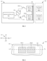
- FIG. 1 is a schematic illustrating one example of a planar flexible RF tag 100 for use with a real-time location system, in embodiments.
- Planar flexible RF tag 100 includes one antenna patch 102 that electrically connects to a balun 104 that in turn electrically connects to a differential output 123 of an RF transceiver circuit 122.
- a rechargeable battery 112 provides power to RF transceiver circuit 122 and to a microcontroller circuit 120.
- RF transceiver circuit 122 may be implemented as only a transmitter.
- Microcontroller circuit 120 controls RF transceiver circuit 122 via one or more electrical connections.
- Planar flexible RF tag 100 includes a connector 114 for charging rechargeable battery 112, and may further include a charging regulator circuit 110 to regulate electrical power received from connector 114 to charge rechargeable battery 112.
- planar flexible RF tag 100/400 is thin (not having 3D antenna or a thick battery), flexible (having components mounted on a flexible substrate and a flexible rechargeable battery) and light weight (the thin efficient operation does not require the use of a single-use higher powered battery), it is much less obtrusive and therefore more widely acceptable for use in tracking athletes and objects in hostile environments.
- planar flexible RF tag 100/400 allows it to be placed unobtrusively on or in athletic equipment and on or in athletic clothing.
- a lower surface 304/704 of planar flexible RF tag 100/400 has an adhesive coating that allows planar flexible RF tag 100/400 to adhere to a surface (e.g., sports equipment, helmet, clothing, skin of the athlete).
- the adhesive is protected by a removable layer that allows planar flexible RF tag 100/400 to be applied using a technique similar to applying a Band-Aid.
- planar flexible RF tag 100/400 may be attached to a bicycle to allow a real-time location system to track the movement of that bicycle and the rider.
- planar flexible RF tag 100/400 is attached to a lanyard and/or worn like a pendant. Thereby, a golfer may wear planar flexible RF tag 100/400 around their neck for example.
- rechargeable battery 112/412 is thin and flexible, thereby also allowing planar flexible RF tag 100/400 to be flexible. This alone is a considerable advance in technology for tracking athletes since planar flexible RF tag 100/400, by being flexible and thin, may thereby provide for easier, less obtrusive placement in athletic equipment and/or clothing.
- Antenna patch 102 and planar complementary patch antenna 403 reduce the overall thickness of planar flexible RF tag 100/400 since the conventionally used 3D antenna design is not required. Further, antenna patch 102 and planar complementary patch antenna 403 have reduced fragility since there is no 3D structure mounted away from the supporting substrate that requires protection.
- planar flexible RF tag 100/400 may utilize flexible substrate 202/602 to support each of antenna patch 102 and planar complementary patch antenna 403, components 302/702, and rechargeable battery 112/412. This flexibility significantly advances the art of RF tracking systems where prior art UWB RF tags were built using rigid circuit boards and required hard, thick housings. In the prior art, these rigid PCBs were required to support and protect the 3D antenna, and to support the larger, heavier and non-flexibly battery.
- UWB tags were designed from discrete components that were interconnected by etched tracked on a printed circuit board. At UWB frequencies absolutely everything, including the etches, effects the performance of the circuit. For this reason, etches need to be considered components of the UWB and so having them flexing, stretching and contracting wreaks havoc with circuit performance.
- UWB components and connectivity may be implemented within an integrated circuit that attaches to flexible substrate 202/602. Thus, UWB circuitry itself is not susceptible to bending within planar flexible RF tag 100/400.
- planar flexible RF tag 100/400 is flexible, when incorporated within athletic equipment, configured within clothing, or attaches directly to an athlete, inevitable bending of planar flexible RF tag 100/400 is accommodated through the flexibility rather than resulting in breakage. Thus, planar flexible RF tag 100/400 is less fragile that prior art RF tags. Thus, this flexibility also makes planar flexible RF tag 100/400 more adaptable to the environment, the athlete, the clothing, and/or the equipment upon which they are mounted on or in.
Landscapes
- Engineering & Computer Science (AREA)
- Computer Networks & Wireless Communication (AREA)
- Power Engineering (AREA)
- Waveguide Aerials (AREA)
- Details Of Aerials (AREA)
- Support Of Aerials (AREA)
Claims (13)
- Planares, flexibles Hochfrequenz (HF)-Etikett (400) zur Verwendung in einem Echtzeit-Ortungssystem,
wobei das planare, flexible HF-Etikett umfasst:ein flexibles Substrat (602);eine planare komplementäre Patch-Antenne (403), die ein erstes und ein zweites Antennenfeld (402) und einen Differenzeingang (401) umfasst, wobei das erste und das zweite Antennenfeld auf einer ersten Seite des flexiblen Substrats positioniert sind;eine HF-Senderschaltung, die auf dem flexiblen Substrat positioniert ist und einen Differenzausgang (423) aufweist, der elektrisch mit dem Differenzeingang (401) gekoppelt ist; undeine Mikrocontrollerschaltung (420), die auf dem flexiblen Substrat positioniert und elektrisch gekoppelt ist, um die HF-Senderschaltung zu steuern, um die planare komplementäre Patch-Antenne anzusteuern, um ein Funksignal zu übertragen;dadurch gekennzeichnet, dass es ferner umfasst:eine erste Entkopplungsschaltung (404), die auf dem flexiblen Substrat positioniert und elektrisch mit dem ersten Antennenfeld gekoppelt ist;eine zweite Entkopplungsschaltung (404), die auf dem flexiblen Substrat positioniert und elektrisch mit dem zweiten Antennenfeld gekoppelt ist;einen Vollwellengleichrichter, der auf dem flexiblen Substrat positioniert ist und eine erste Hälfte (406) aufweist, die elektrisch mit der ersten Entkopplungsschaltung gekoppelt ist, sowie eine zweite Hälfte (407), die elektrisch mit der zweiten Entkopplungsschaltung gekoppelt ist; undeine Ladereglerschaltung (410), die auf dem flexiblen Substrat positioniert und elektrisch mit dem Vollwellengleichrichter gekoppelt ist, um Strom über das erste und das zweite Antennenfeld von einer Ladevorrichtung (500) zu empfangen, die kapazitiv mit dem ersten und dem zweiten Antennenfeld gekoppelt ist. - Planares, flexibles HF-Etikett nach Anspruch 1, ferner umfassend eine wiederaufladbare Batterie (412) zur Versorgung der HF-Senderschaltung und der Mikrocontrollerschaltung.
- Planares, flexibles HF-Etikett nach Anspruch 2, ferner umfassend ein flexibles wasserdichtes Gehäuse (430), das das flexible Substrat, die planare komplementäre Patch-Antenne (403), die HF-Senderschaltung, die Mikrocontrollerschaltung und die wiederaufladbare Batterie einkapselt.
- Planares, flexibles HF-Etikett nach Anspruch 3, ferner umfassend einen elektrischen Verbinder (114), der zumindest teilweise außerhalb des flexiblen wasserdichten Gehäuses angeordnet ist, um elektrische Energie zum Aufladen der wiederaufladbaren Batterie (412) bereitzustellen.
- Planares, flexibles HF-Etikett nach Anspruch 4, ferner umfassend eine Reglerschaltung (410), die auf dem flexiblen Substrat und innerhalb des flexiblen wasserdichten Gehäuses angeordnet und elektrisch mit dem elektrischen Verbinder (114) und der wiederaufladbaren Batterie (412) verbunden ist, so dass die Reglerschaltung die elektrische Leistung vom elektrischen Verbinder zum Laden der wiederaufladbaren Batterie regelt.
- Planares, flexibles HF-Etikett nach Anspruch 5, wobei die planare komplementäre Patch-Antenne eine Geometrie aufweist, die dazu ausgelegt ist, das Funksignal unter Verwendung der Ultrabreitbandtechnologie zu übertragen.
- Planares, flexibles HF-Etikett nach Anspruch 6, wobei die Geometrie eine Größe, eine Form und einen Abstand des ersten und des zweiten Antennenfeldes definiert.
- Planares, flexibles HF-Etikett nach Anspruch 7, wobei die Form rechteckig ist.
- Planares, flexibles HF-Etikett nach Anspruch 1, ferner umfassend ein wasserdichtes und dauerhaft versiegeltes Gehäuse (430).
- Planares, flexibles HF-Etikett nach Anspruch 9, ferner umfassend eine Vorrichtung zur Befestigung des planaren, flexiblen HF-Etiketts an der Kleidung und/oder der Ausrüstung einer Person, um die Verfolgung der Person zu ermöglichen.
- Planares, flexibles HF-Etikett nach Anspruch 9 oder 10, wobei das wasserdichte und dauerhaft versiegelte Gehäuse flexibel ist.
- Planares, flexibles HF-Etikett nach einem der Ansprüche 9 bis 11, ferner umfassend einen Klebstoff, der auf einer Unterseite des wasserdichten und dauerhaft versiegelten Gehäuses vorgesehen ist, um das planare, flexible HF-Etikett an einer Oberfläche eines zu verfolgenden Objekts anzukleben.
- Planares, flexibles HF-Etikett nach Anspruch 2 allein oder in Kombination mit einem der Ansprüche 3 bis 12, wobei die wiederaufladbare Batterie flexibel ist und es dem planaren, flexiblen HF-Etikett erlaubt, ohne Beschädigung oder Leistungsverlust umgebogen zu werden.
Applications Claiming Priority (2)
| Application Number | Priority Date | Filing Date | Title |
|---|---|---|---|
| US201662361359P | 2016-07-12 | 2016-07-12 | |
| PCT/US2017/041672 WO2018013658A1 (en) | 2016-07-12 | 2017-07-12 | Planar flexible rf tag and charging device |
Publications (4)
| Publication Number | Publication Date |
|---|---|
| EP3485530A1 EP3485530A1 (de) | 2019-05-22 |
| EP3485530A4 EP3485530A4 (de) | 2020-04-01 |
| EP3485530B1 true EP3485530B1 (de) | 2025-07-02 |
| EP3485530C0 EP3485530C0 (de) | 2025-07-02 |
Family
ID=60941733
Family Applications (1)
| Application Number | Title | Priority Date | Filing Date |
|---|---|---|---|
| EP17828365.1A Active EP3485530B1 (de) | 2016-07-12 | 2017-07-12 | Flaches flexibles hf-etikett und ladevorrichtung |
Country Status (5)
| Country | Link |
|---|---|
| US (2) | US11171405B2 (de) |
| EP (1) | EP3485530B1 (de) |
| AU (2) | AU2017296326A1 (de) |
| CA (1) | CA3030288A1 (de) |
| WO (1) | WO2018013658A1 (de) |
Families Citing this family (11)
| Publication number | Priority date | Publication date | Assignee | Title |
|---|---|---|---|---|
| EP3485530B1 (de) * | 2016-07-12 | 2025-07-02 | Isolynx, LLC | Flaches flexibles hf-etikett und ladevorrichtung |
| US20190067979A1 (en) * | 2017-08-28 | 2019-02-28 | Wiwaves, Inc. | Wireless charging device and system |
| US10960955B2 (en) * | 2017-12-15 | 2021-03-30 | Sram, Llc | Bicycle electrical control device and system |
| US11394121B2 (en) * | 2018-11-01 | 2022-07-19 | Isolynx, Llc | Nonplanar complementary patch antenna and associated methods |
| JP7463290B2 (ja) * | 2018-11-22 | 2024-04-08 | 株式会社半導体エネルギー研究所 | 半導体装置 |
| CN109768386A (zh) * | 2019-02-01 | 2019-05-17 | 永康国科康复工程技术有限公司 | 一种可拉伸天线及其制备方法 |
| US11404786B2 (en) * | 2019-07-03 | 2022-08-02 | City University Of Hong Kong | Planar complementary antenna and related antenna array |
| USD931840S1 (en) | 2019-07-19 | 2021-09-28 | Zebra Technologies Corporation | Tag housing |
| US20240171944A1 (en) * | 2022-11-22 | 2024-05-23 | Wiser Systems, Inc. | Methods for tracking moving objects using mobile location devices and related systems and computer program products |
| WO2024176240A1 (en) * | 2023-02-26 | 2024-08-29 | Remote Energy Ltd. | Method and apparatus for capacitive wireless power transmission |
| US12431615B2 (en) * | 2023-10-27 | 2025-09-30 | Texas Instruments Incorporated | Millimeter wave quantum sensor device |
Citations (2)
| Publication number | Priority date | Publication date | Assignee | Title |
|---|---|---|---|---|
| US20100134292A1 (en) * | 2008-12-03 | 2010-06-03 | Deavours Daniel D | Radio-frequency identification device with foam substrate |
| US7868841B2 (en) * | 2007-04-11 | 2011-01-11 | Vubiq Incorporated | Full-wave di-patch antenna |
Family Cites Families (59)
| Publication number | Priority date | Publication date | Assignee | Title |
|---|---|---|---|---|
| US5776278A (en) * | 1992-06-17 | 1998-07-07 | Micron Communications, Inc. | Method of manufacturing an enclosed transceiver |
| US5757327A (en) * | 1994-07-29 | 1998-05-26 | Mitsumi Electric Co., Ltd. | Antenna unit for use in navigation system |
| US8280682B2 (en) * | 2000-12-15 | 2012-10-02 | Tvipr, Llc | Device for monitoring movement of shipped goods |
| DE19701357C2 (de) * | 1997-01-16 | 2003-02-27 | Schleifring Und Appbau Gmbh | Vorrichtung zur kontaktlosen Energieübertragung zwischen gegeneinander beweglichen Teilen |
| US20030201946A1 (en) * | 2002-04-30 | 2003-10-30 | Hui-Ying Sheen | Antenna with enclosed receptors |
| WO2004032343A2 (en) * | 2002-10-02 | 2004-04-15 | University Of Florida | Single chip radio with integrated antenna |
| JP4176613B2 (ja) * | 2003-10-24 | 2008-11-05 | 株式会社ワイケーシー | 超広帯域アンテナ及び超広帯域高周波回路モジュール |
| US8045947B2 (en) * | 2004-09-17 | 2011-10-25 | Massachusetts Institute Of Technology | RF power extracting circuit and related techniques |
| US7844306B2 (en) * | 2005-05-24 | 2010-11-30 | Powercast Corporation | Power transmission network |
| EP1997238B1 (de) * | 2006-03-21 | 2011-08-24 | TMMS Co., Ltd. | Einrichtung zum transportieren von energie durch partialinfluenz durch ein dielektrisches medium |
| DE102006019688B4 (de) | 2006-04-27 | 2014-10-23 | Vega Grieshaber Kg | Patchantenne mit Keramikscheibe als Abdeckung |
| US7528720B2 (en) * | 2006-04-28 | 2009-05-05 | Motorola, Inc. | Radio frequency identification tag-based task effectuation method and apparatus |
| US7761115B2 (en) * | 2006-05-30 | 2010-07-20 | Broadcom Corporation | Multiple mode RF transceiver and antenna structure |
| US20090001930A1 (en) * | 2007-06-29 | 2009-01-01 | Nokia Corporation | Electronic apparatus and associated methods |
| FR2920061A1 (fr) * | 2007-08-17 | 2009-02-20 | Patrick Camurati | Procede et dispositif de transport, distribution et gestion de l'energie electrique par couplage longitudinal a distance en champ proche entre dipoles electriques |
| CA2699680C (en) * | 2007-10-08 | 2016-06-07 | Sensormatic Electronics, LLC | Rfid patch antenna with coplanar reference ground and floating grounds |
| CA2761635C (en) | 2010-03-24 | 2012-07-10 | Mina Danesh | Integrated photovoltaic cell and radio-frequency antenna |
| JP5838324B2 (ja) | 2010-05-03 | 2016-01-06 | パナソニックIpマネジメント株式会社 | 発電装置、発電システム、および無線電力伝送装置 |
| NZ718566A (en) * | 2010-11-19 | 2017-10-27 | Isolynx Llc | Associative object tracking systems and methods |
| DE112011103929B4 (de) * | 2010-11-26 | 2025-11-13 | Semiconductor Energy Laboratory Co.,Ltd. | Leistungssendevorrichtung und System zur drahtlosen Übertragung von Leistung, das diese enthält |
| US9675809B2 (en) * | 2011-07-14 | 2017-06-13 | Cyberonics, Inc. | Circuit, system and method for far-field radiative powering of an implantable medical device |
| US9256773B2 (en) * | 2011-07-27 | 2016-02-09 | Féinics Amatech Teoranta | Capacitive coupling of an RFID tag with a touch screen device acting as a reader |
| US9698761B2 (en) * | 2011-08-16 | 2017-07-04 | Philips Lighting Holding B.V. | Dynamic resonant matching circuit for wireless power receivers |
| US9166276B2 (en) | 2012-10-30 | 2015-10-20 | Texas Instruments Incorporated | Multifunction single antenna for contactless systems |
| US9137637B2 (en) | 2013-03-13 | 2015-09-15 | King Abdullah University Of Science And Technology | Printed tag real-time tracking |
| US9002485B2 (en) | 2013-06-06 | 2015-04-07 | Zih Corp. | Method, apparatus, and computer program product for performance analytics determining play models and outputting events based on real-time data for proximity and movement of objects |
| US10437658B2 (en) * | 2013-06-06 | 2019-10-08 | Zebra Technologies Corporation | Method, apparatus, and computer program product for collecting and displaying sporting event data based on real time data for proximity and movement of objects |
| US20140362120A1 (en) | 2013-06-06 | 2014-12-11 | Zih Corp. | Method and apparatus for displaying analytics via configurable visualizations |
| US10609762B2 (en) | 2013-06-06 | 2020-03-31 | Zebra Technologies Corporation | Method, apparatus, and computer program product improving backhaul of sensor and other data to real time location system network |
| US9715005B2 (en) | 2013-06-06 | 2017-07-25 | Zih Corp. | Method, apparatus, and computer program product improving real time location systems with multiple location technologies |
| US20150149250A1 (en) | 2013-06-06 | 2015-05-28 | Zih Corp. | Method, apparatus, and computer program product to ascertain supply and demand analytics and outputting events based on real-time data for proximity and movement of individuals and objects |
| US20150178817A1 (en) | 2013-06-06 | 2015-06-25 | Zih Corp. | Method, apparatus, and computer program product for enhancement of fan experience based on location data |
| US9517417B2 (en) | 2013-06-06 | 2016-12-13 | Zih Corp. | Method, apparatus, and computer program product for performance analytics determining participant statistical data and game status data |
| US9699278B2 (en) | 2013-06-06 | 2017-07-04 | Zih Corp. | Modular location tag for a real time location system network |
| JP6032366B2 (ja) * | 2013-07-01 | 2016-11-24 | 株式会社村田製作所 | ワイヤレス電力伝送システム |
| WO2015061780A1 (en) | 2013-10-25 | 2015-04-30 | Greene Charles E | Bi-stable display tag |
| US9690962B2 (en) | 2014-01-10 | 2017-06-27 | Vdw Design, Llc | Radio-frequency identification tags |
| US9923380B2 (en) * | 2014-03-07 | 2018-03-20 | Intel Corporation | Capacitive element coupling in wireless power |
| US9626616B2 (en) | 2014-06-05 | 2017-04-18 | Zih Corp. | Low-profile real-time location system tag |
| EP3152585B1 (de) | 2014-06-06 | 2022-04-27 | Zebra Technologies Corporation | Verfahren, vorrichtung und computerprogrammprodukt zur verbesserung von echtzeitpositionsbestimmungssystemen mit mehreren positionsbestimmungstechnologien |
| CN204029975U (zh) * | 2014-07-04 | 2014-12-17 | 光宝电子(广州)有限公司 | 双馈入双极化的高方向性阵列天线系统 |
| KR101656260B1 (ko) * | 2015-01-05 | 2016-09-09 | 주식회사 아모센스 | 무선충전용 차폐유닛 및 이를 포함하는 무선전력 충전모듈 |
| WO2016196863A1 (en) | 2015-06-05 | 2016-12-08 | Zih Corp. | Modular location tag for a real time location system network |
| US10128660B1 (en) * | 2015-11-13 | 2018-11-13 | X Development Llc | Wireless solar power delivery |
| ITUB20156047A1 (it) * | 2015-12-01 | 2017-06-01 | St Microelectronics Srl | Sistema di isolamento galvanico, apparecchiatura e procedimento |
| AU2016362964B2 (en) * | 2015-12-01 | 2019-11-21 | Isolynx, Llc | Folded UWB monopole antenna for body mounted transmitter and manufacturing method |
| US10476293B2 (en) * | 2016-04-06 | 2019-11-12 | Analog Devices, Inc. | Flexible energy harvesting antenna |
| EP3485530B1 (de) * | 2016-07-12 | 2025-07-02 | Isolynx, LLC | Flaches flexibles hf-etikett und ladevorrichtung |
| WO2018119445A1 (en) * | 2016-12-23 | 2018-06-28 | Stamina Energy, LLC | Wireless energy harvesting |
| US10381878B1 (en) * | 2016-12-29 | 2019-08-13 | X Development Llc | Adapter for electronic devices |
| US10439442B2 (en) * | 2017-01-24 | 2019-10-08 | Energous Corporation | Microstrip antennas for wireless power transmitters |
| NO345389B1 (en) * | 2017-03-15 | 2021-01-11 | Norbit Its | Patch antenna feed |
| US10468776B2 (en) * | 2017-05-04 | 2019-11-05 | Elwha Llc | Medical applications using tunable metamaterial systems and methods |
| US11522234B2 (en) * | 2017-09-06 | 2022-12-06 | Semiconductor Energy Laboratory Co., Ltd. | Semiconductor device, battery unit, and battery module |
| KR102428929B1 (ko) * | 2018-01-29 | 2022-08-05 | 삼성전자주식회사 | 기생 도전성 판을 포함하는 안테나 구조 |
| US11394121B2 (en) * | 2018-11-01 | 2022-07-19 | Isolynx, Llc | Nonplanar complementary patch antenna and associated methods |
| JP2022523022A (ja) * | 2019-01-28 | 2022-04-21 | エナージャス コーポレイション | 無線送電のための小型アンテナ用のシステム及び方法 |
| EP4042541A1 (de) * | 2019-10-07 | 2022-08-17 | Telefonaktiebolaget Lm Ericsson (Publ) | Drahtlose stromübertragung |
| US20230275467A1 (en) * | 2022-02-25 | 2023-08-31 | Chairge Llc | Wireless charging system and method |
-
2017
- 2017-07-12 EP EP17828365.1A patent/EP3485530B1/de active Active
- 2017-07-12 CA CA3030288A patent/CA3030288A1/en active Pending
- 2017-07-12 AU AU2017296326A patent/AU2017296326A1/en not_active Abandoned
- 2017-07-12 WO PCT/US2017/041672 patent/WO2018013658A1/en not_active Ceased
- 2017-07-12 US US15/648,315 patent/US11171405B2/en active Active
-
2021
- 2021-11-08 US US17/521,632 patent/US20220069436A1/en not_active Abandoned
-
2022
- 2022-05-04 AU AU2022203000A patent/AU2022203000B2/en not_active Ceased
Patent Citations (2)
| Publication number | Priority date | Publication date | Assignee | Title |
|---|---|---|---|---|
| US7868841B2 (en) * | 2007-04-11 | 2011-01-11 | Vubiq Incorporated | Full-wave di-patch antenna |
| US20100134292A1 (en) * | 2008-12-03 | 2010-06-03 | Deavours Daniel D | Radio-frequency identification device with foam substrate |
Also Published As
| Publication number | Publication date |
|---|---|
| AU2017296326A1 (en) | 2019-02-07 |
| WO2018013658A1 (en) | 2018-01-18 |
| CA3030288A1 (en) | 2018-01-18 |
| EP3485530A1 (de) | 2019-05-22 |
| US20220069436A1 (en) | 2022-03-03 |
| EP3485530A4 (de) | 2020-04-01 |
| US11171405B2 (en) | 2021-11-09 |
| US20180019513A1 (en) | 2018-01-18 |
| AU2022203000B2 (en) | 2024-01-18 |
| AU2022203000A1 (en) | 2022-06-09 |
| NZ750137A (en) | 2021-10-29 |
| EP3485530C0 (de) | 2025-07-02 |
Similar Documents
| Publication | Publication Date | Title |
|---|---|---|
| AU2022203000B2 (en) | Planar flexible rf tag and charging device | |
| US8690070B2 (en) | Wireless IC device component and wireless IC device | |
| WO2015088875A1 (en) | Wireless charging of clothing and smart fabrics | |
| EP3210278B1 (de) | Verteilte stromempfangselemente zur drahtlosen stromübertragung | |
| US9330354B2 (en) | Radio IC device | |
| JP4867830B2 (ja) | 無線icデバイス | |
| WO2020102511A2 (en) | Systems for receiving electromagnetic energy using antennas that are minimally affected by the presence of the human body | |
| US9935362B2 (en) | Systems, apparatuses and methods for biometric sensing using conformal flexible antenna | |
| US20200144724A1 (en) | Nonplanar complementary patch antenna and associated methods | |
| WO2003092116A2 (en) | Energy source with a slot antenna formed in the body | |
| KR101466440B1 (ko) | 이중 대역을 가지는 인체 착용형 안테나 | |
| WO2015009892A1 (en) | Method for 3 dimensional pocket-forming | |
| US10476293B2 (en) | Flexible energy harvesting antenna | |
| US20120132718A1 (en) | Transponder tagged object and method for manufacturing a transponder tagged object | |
| GB2431522A (en) | Slot antenna formed in the casing of a wrist-wearable device | |
| Hughes et al. | An on-body UHF RFID tag with DDRR antenna for healthcare data streaming applications | |
| JP5299351B2 (ja) | 無線icデバイス | |
| NZ750137B2 (en) | Planar flexible rf tag and charging device | |
| KR100654623B1 (ko) | 무선 전력 전달의 전력 수신을 향상시키기 위한 다수의 다이폴 렉테나로 이루어진 렉테나 어레이 시스템 | |
| US10476135B2 (en) | Portable electronic device with embedded antenna | |
| Vital | A Novel Array of Strongly Coupled Magnetic Resonators for Misalignment-Resilient Wireless Power Transfer, Harvesting, and Sensing in Wearable Applications | |
| CN102467675B (zh) | 一种射频标签及其谐振电路结构 | |
| KR102127812B1 (ko) | 통신 모듈을 포함하는 전자기기 | |
| Song et al. | Textile Radio Frequency Active Devices and Systems: Wireless Communication and Energy Harvesting |
Legal Events
| Date | Code | Title | Description |
|---|---|---|---|
| STAA | Information on the status of an ep patent application or granted ep patent |
Free format text: STATUS: THE INTERNATIONAL PUBLICATION HAS BEEN MADE |
|
| PUAI | Public reference made under article 153(3) epc to a published international application that has entered the european phase |
Free format text: ORIGINAL CODE: 0009012 |
|
| STAA | Information on the status of an ep patent application or granted ep patent |
Free format text: STATUS: REQUEST FOR EXAMINATION WAS MADE |
|
| 17P | Request for examination filed |
Effective date: 20190204 |
|
| AK | Designated contracting states |
Kind code of ref document: A1 Designated state(s): AL AT BE BG CH CY CZ DE DK EE ES FI FR GB GR HR HU IE IS IT LI LT LU LV MC MK MT NL NO PL PT RO RS SE SI SK SM TR |
|
| AX | Request for extension of the european patent |
Extension state: BA ME |
|
| DAV | Request for validation of the european patent (deleted) | ||
| DAX | Request for extension of the european patent (deleted) | ||
| A4 | Supplementary search report drawn up and despatched |
Effective date: 20200304 |
|
| RIC1 | Information provided on ipc code assigned before grant |
Ipc: H01Q 9/28 20060101ALI20200227BHEP Ipc: H01Q 1/00 20060101AFI20200227BHEP Ipc: H02J 7/02 20160101ALI20200227BHEP Ipc: H01Q 1/22 20060101ALI20200227BHEP Ipc: H01Q 21/06 20060101ALI20200227BHEP Ipc: H01Q 1/27 20060101ALI20200227BHEP Ipc: H02J 50/20 20160101ALI20200227BHEP Ipc: H01Q 1/12 20060101ALI20200227BHEP Ipc: H01Q 21/00 20060101ALI20200227BHEP |
|
| STAA | Information on the status of an ep patent application or granted ep patent |
Free format text: STATUS: EXAMINATION IS IN PROGRESS |
|
| 17Q | First examination report despatched |
Effective date: 20211201 |
|
| REG | Reference to a national code |
Ref country code: DE Ref legal event code: R079 Free format text: PREVIOUS MAIN CLASS: H01Q0001000000 Ipc: H01Q0001220000 Ref country code: DE Ref legal event code: R079 Ref document number: 602017090332 Country of ref document: DE Free format text: PREVIOUS MAIN CLASS: H01Q0001000000 Ipc: H01Q0001220000 |
|
| REG | Reference to a national code |
Ref country code: DE Ref legal event code: R079 Ref document number: 602017090332 Country of ref document: DE Free format text: PREVIOUS MAIN CLASS: H01Q0001220000 Ipc: H01Q0001240000 Ref country code: DE Ref legal event code: R079 Free format text: PREVIOUS MAIN CLASS: H01Q0001220000 Ipc: H01Q0001240000 |
|
| RIC1 | Information provided on ipc code assigned before grant |
Ipc: H04W 4/02 20180101ALI20241129BHEP Ipc: H02J 50/00 20160101ALI20241129BHEP Ipc: H02J 50/20 20160101ALI20241129BHEP Ipc: H01Q 9/28 20060101ALI20241129BHEP Ipc: H01Q 1/27 20060101ALI20241129BHEP Ipc: H01Q 1/22 20060101AFI20241129BHEP |
|
| GRAP | Despatch of communication of intention to grant a patent |
Free format text: ORIGINAL CODE: EPIDOSNIGR1 |
|
| STAA | Information on the status of an ep patent application or granted ep patent |
Free format text: STATUS: GRANT OF PATENT IS INTENDED |
|
| RIC1 | Information provided on ipc code assigned before grant |
Ipc: H04W 4/02 20180101ALI20241217BHEP Ipc: H02J 50/00 20160101ALI20241217BHEP Ipc: H02J 50/20 20160101ALI20241217BHEP Ipc: H01Q 9/28 20060101ALI20241217BHEP Ipc: H01Q 1/27 20060101ALI20241217BHEP Ipc: H01Q 1/22 20060101ALI20241217BHEP Ipc: H01Q 1/24 20060101AFI20241217BHEP |
|
| INTG | Intention to grant announced |
Effective date: 20250122 |
|
| GRAS | Grant fee paid |
Free format text: ORIGINAL CODE: EPIDOSNIGR3 |
|
| GRAA | (expected) grant |
Free format text: ORIGINAL CODE: 0009210 |
|
| STAA | Information on the status of an ep patent application or granted ep patent |
Free format text: STATUS: THE PATENT HAS BEEN GRANTED |
|
| AK | Designated contracting states |
Kind code of ref document: B1 Designated state(s): AL AT BE BG CH CY CZ DE DK EE ES FI FR GB GR HR HU IE IS IT LI LT LU LV MC MK MT NL NO PL PT RO RS SE SI SK SM TR |
|
| REG | Reference to a national code |
Ref country code: GB Ref legal event code: FG4D |
|
| REG | Reference to a national code |
Ref country code: CH Ref legal event code: EP |
|
| REG | Reference to a national code |
Ref country code: DE Ref legal event code: R096 Ref document number: 602017090332 Country of ref document: DE |
|
| REG | Reference to a national code |
Ref country code: IE Ref legal event code: FG4D |
|
| U01 | Request for unitary effect filed |
Effective date: 20250801 |
|
| U07 | Unitary effect registered |
Designated state(s): AT BE BG DE DK EE FI FR IT LT LU LV MT NL PT RO SE SI Effective date: 20250812 |
|
| PG25 | Lapsed in a contracting state [announced via postgrant information from national office to epo] |
Ref country code: IS Free format text: LAPSE BECAUSE OF FAILURE TO SUBMIT A TRANSLATION OF THE DESCRIPTION OR TO PAY THE FEE WITHIN THE PRESCRIBED TIME-LIMIT Effective date: 20251102 |
|
| PG25 | Lapsed in a contracting state [announced via postgrant information from national office to epo] |
Ref country code: NO Free format text: LAPSE BECAUSE OF FAILURE TO SUBMIT A TRANSLATION OF THE DESCRIPTION OR TO PAY THE FEE WITHIN THE PRESCRIBED TIME-LIMIT Effective date: 20251002 |
|
| PG25 | Lapsed in a contracting state [announced via postgrant information from national office to epo] |
Ref country code: HR Free format text: LAPSE BECAUSE OF FAILURE TO SUBMIT A TRANSLATION OF THE DESCRIPTION OR TO PAY THE FEE WITHIN THE PRESCRIBED TIME-LIMIT Effective date: 20250702 |
|
| PG25 | Lapsed in a contracting state [announced via postgrant information from national office to epo] |
Ref country code: GR Free format text: LAPSE BECAUSE OF FAILURE TO SUBMIT A TRANSLATION OF THE DESCRIPTION OR TO PAY THE FEE WITHIN THE PRESCRIBED TIME-LIMIT Effective date: 20251003 |
|
| PG25 | Lapsed in a contracting state [announced via postgrant information from national office to epo] |
Ref country code: CZ Free format text: LAPSE BECAUSE OF FAILURE TO SUBMIT A TRANSLATION OF THE DESCRIPTION OR TO PAY THE FEE WITHIN THE PRESCRIBED TIME-LIMIT Effective date: 20250702 |
|
| PG25 | Lapsed in a contracting state [announced via postgrant information from national office to epo] |
Ref country code: PL Free format text: LAPSE BECAUSE OF FAILURE TO SUBMIT A TRANSLATION OF THE DESCRIPTION OR TO PAY THE FEE WITHIN THE PRESCRIBED TIME-LIMIT Effective date: 20250702 |
|
| PG25 | Lapsed in a contracting state [announced via postgrant information from national office to epo] |
Ref country code: RS Free format text: LAPSE BECAUSE OF FAILURE TO SUBMIT A TRANSLATION OF THE DESCRIPTION OR TO PAY THE FEE WITHIN THE PRESCRIBED TIME-LIMIT Effective date: 20251002 |
|
| PG25 | Lapsed in a contracting state [announced via postgrant information from national office to epo] |
Ref country code: ES Free format text: LAPSE BECAUSE OF FAILURE TO SUBMIT A TRANSLATION OF THE DESCRIPTION OR TO PAY THE FEE WITHIN THE PRESCRIBED TIME-LIMIT Effective date: 20250702 |